A New Setup for Real-Time Investigations of Optical Fiber Sensors Subjected to Gamma-Rays: Case Study on Long Period Gratings

 ,
,  ,
,  , ,
, ,  and
and 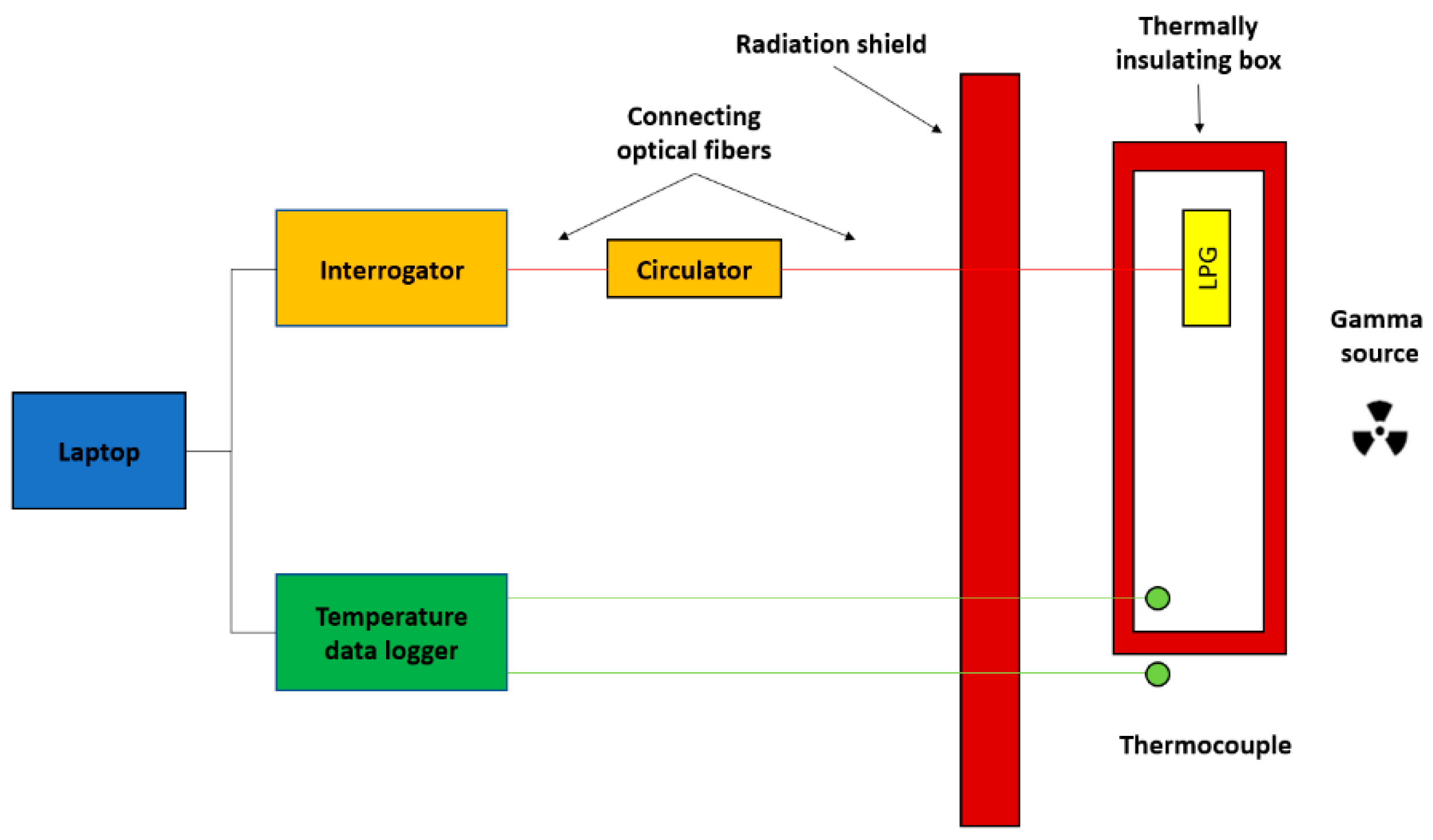
Abstract
:1. Introduction
2. Experimental Setup and Methods
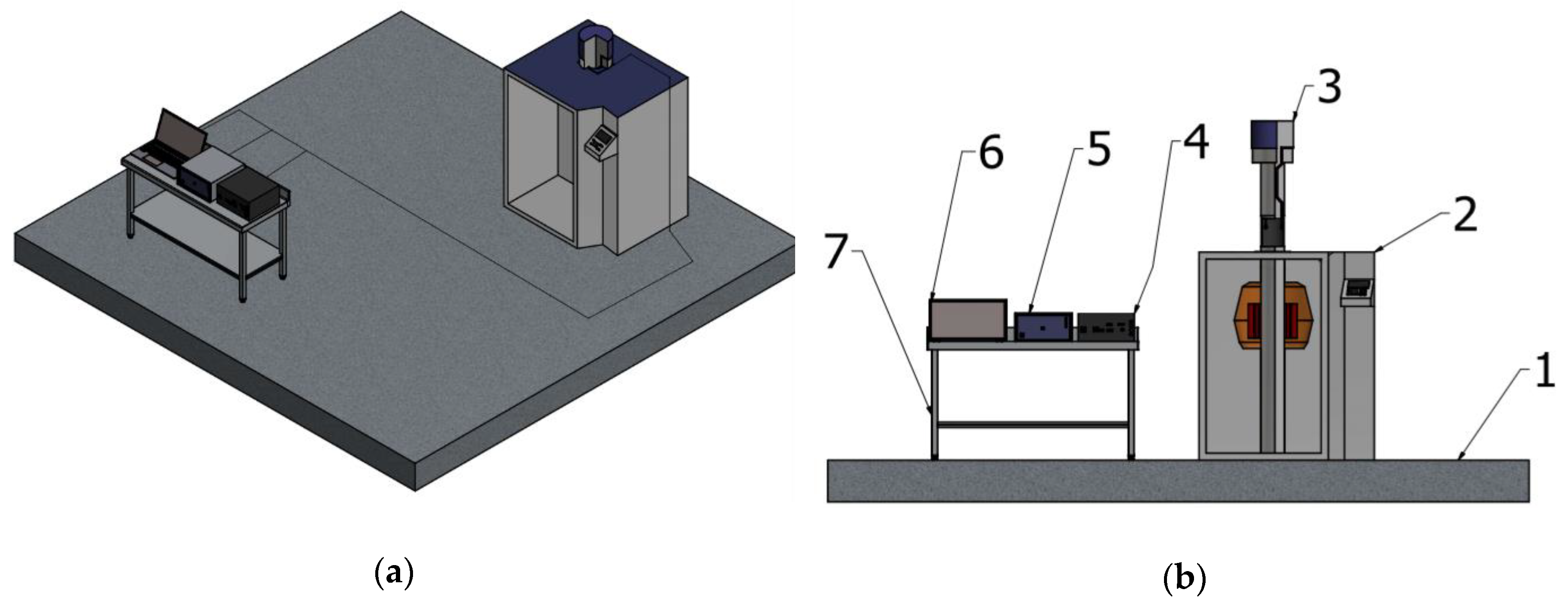
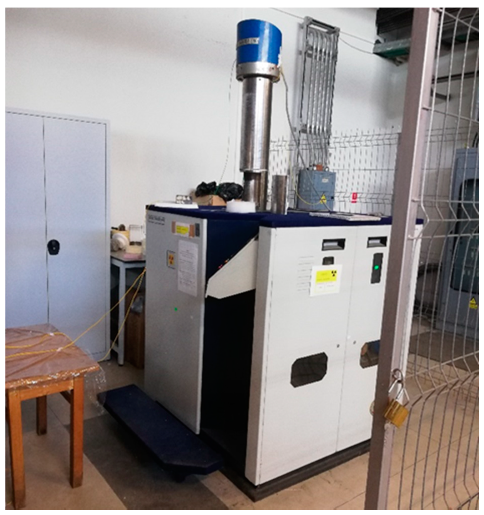
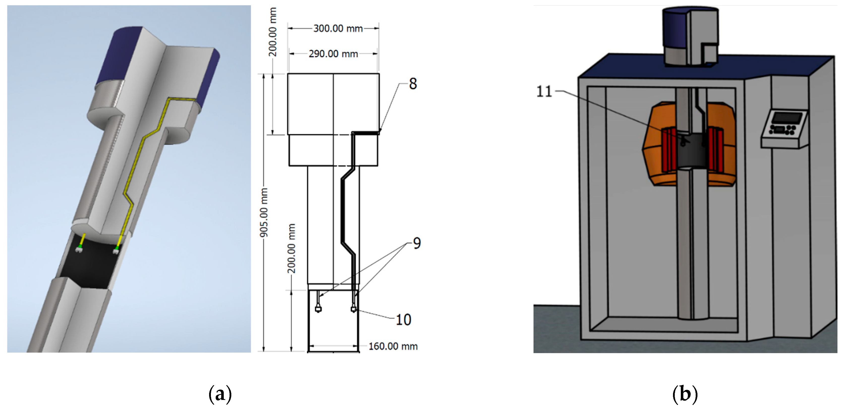
2.1. Irradiation and Measurement Setups
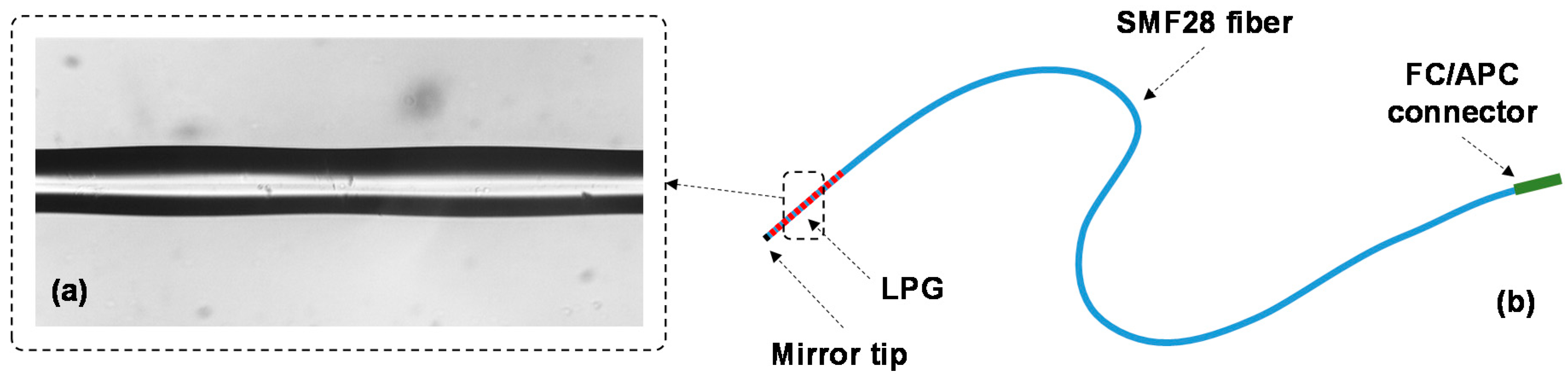
2.2. Fabrication of Long Period Fiber Gratings
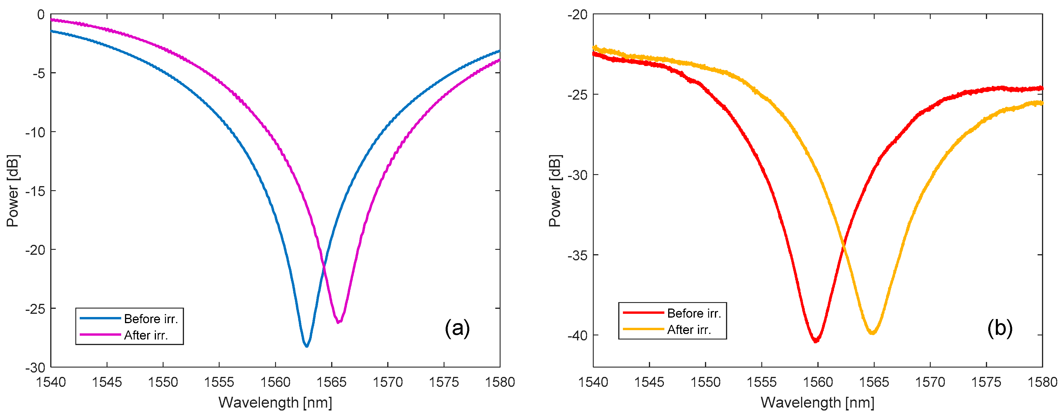
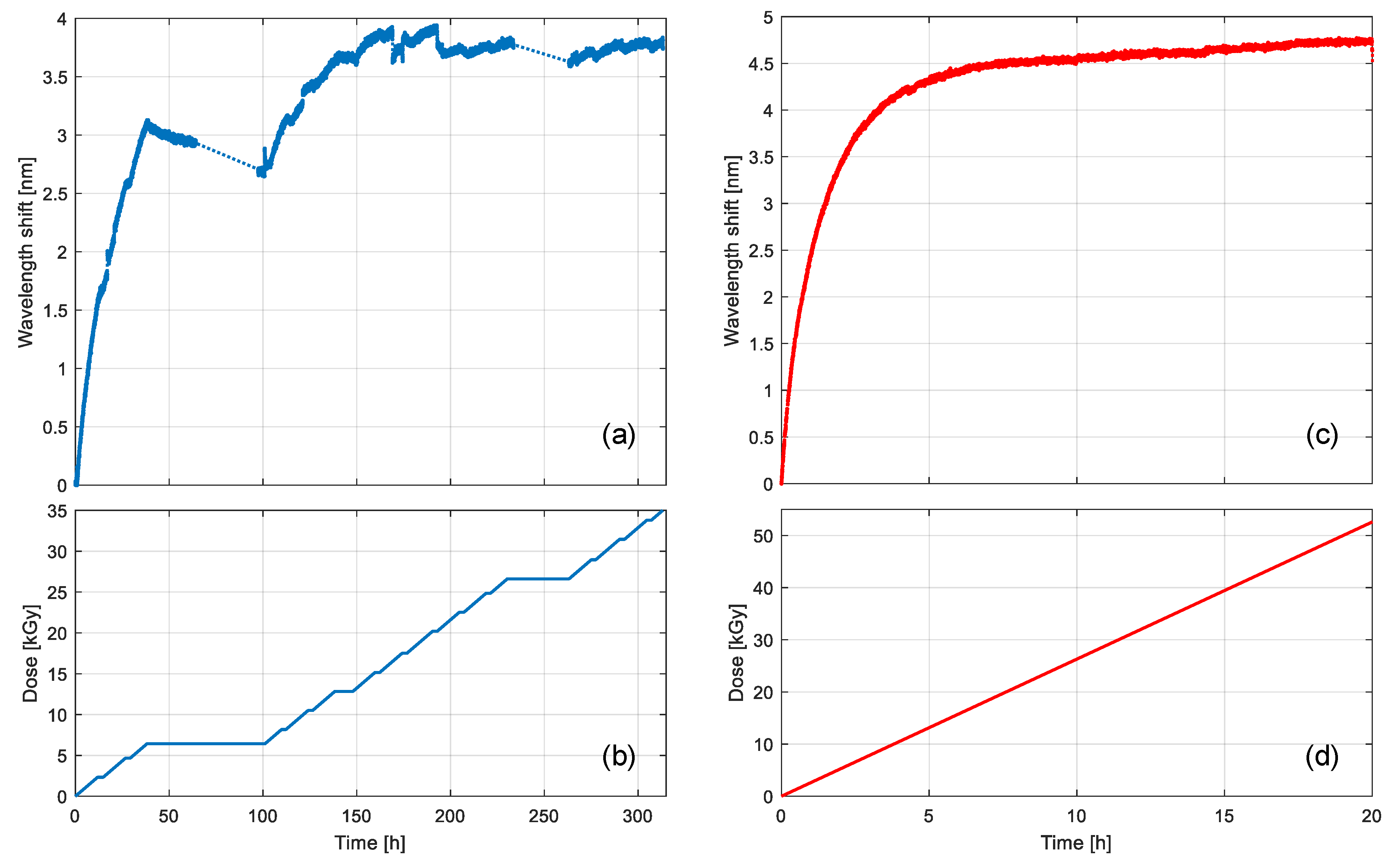
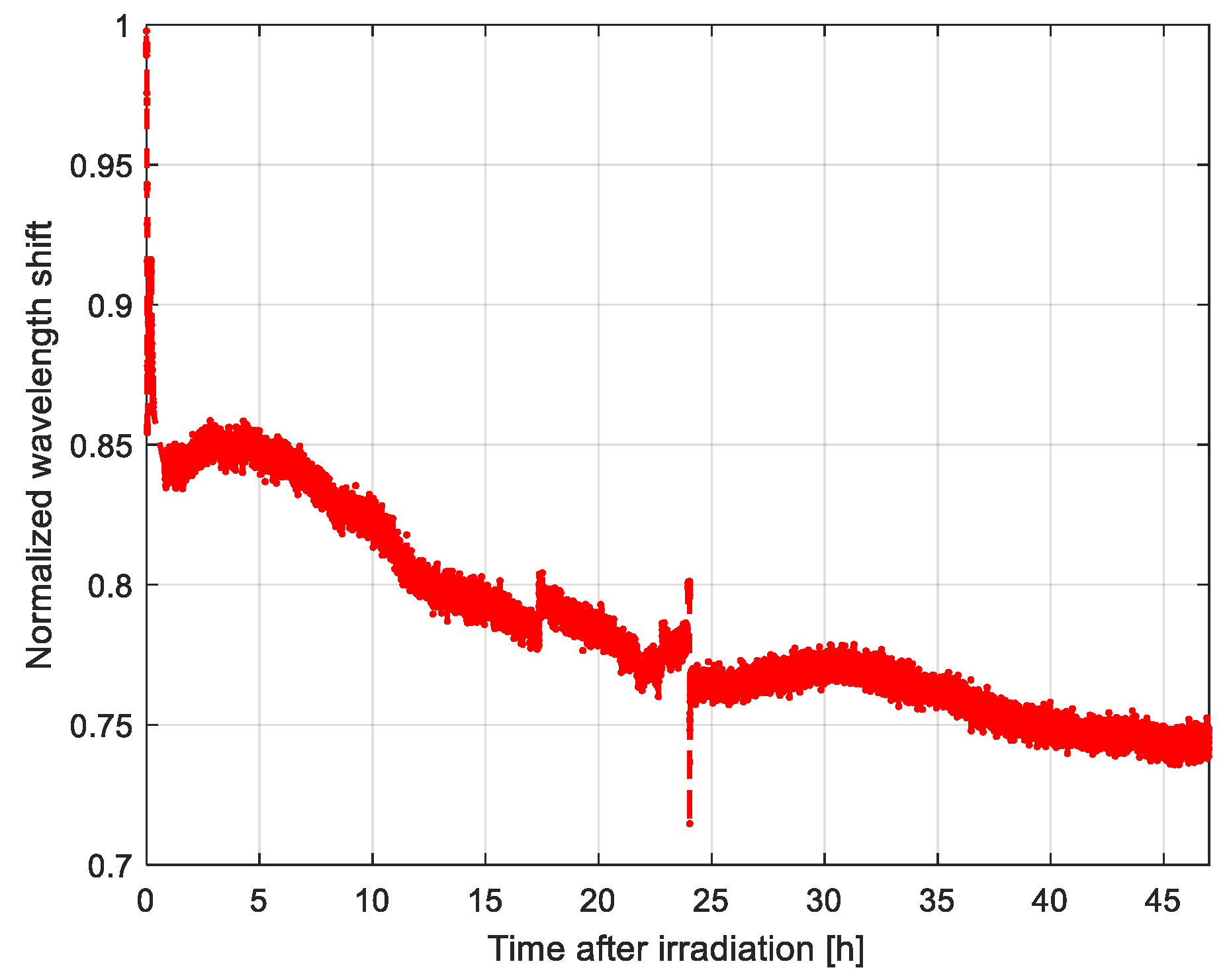
3. Results
4. Discussion and Conclusion
- The total accumulated dose can be set as to be perfectly suitable for any custom experiment, moreover the irradiation is continuous, providing a very stable dose-rate. Specifically, the dose rate is more than 10 times higher than the industrial SVST Co-60 irradiator (2.63 kGy/h versus 0.18 kGy/h), and thus it proved to be much more efficient in terms of time and resources.
- Given the position of the LPG under testing, that is, in the middle of the 60-Co rods and in a narrow space, the radiation homogeneity is optimal.
- There are no uncontrolled temperature and humidity variations to affect the sensors, hence the temperature profile during irradiation is very well known, measured continuously and similar in all tests.
- No external factors affect the experiments, as compared to industrial facilities where the dose rate is dependent on the products being processed and can vary by 20% depending on the product density and loading pattern in the irradiation containers.
- Post-irradiation monitoring is possible without changing the peripherals and the gratings are kept in the same conditions as during the irradiation.
- The costs of an irradiation session with the GC-5000 based setup are around half k€, whereas they can go up to a few tens k€ for the industrial SVST Co-60/B irradiator.
- Although the same radiation standards were applied in both scenarios, according to the IAEA, the GC-5000 involves simpler procedures with regard to labor protection measures, mainly due to the compactness and full automation of the irradiator.
Author Contributions
Funding
Conflicts of Interest
References
- Singh, A.; Engles, D.; Sharma, A.; Singh, M. Temperature sensitivity of long period fiber grating in SMF-28 fiber. Optical 2014, 125, 457–460. [Google Scholar] [CrossRef]
- Sabatier, C.; Lecoeuche, V.; Girard, S.; Melin, G.; Robin, T.; Cadier, B.; Mescia, L.; Morana, A.; Ouerdane, Y.; Boukenter, A.; et al. Distributed optical fiber sensor allowing temperature and strain discrimination in radiation environments. IEEE Trans. Nucl. Sci. 2019, 66, 1651–1656. [Google Scholar] [CrossRef]
- Mei, N.N.; Zhihao, C.; Kin, S.C. Temperature compensation of long-period fiber grating for refractive-index sensing with bending effect. IEEE Photonics Technol. Lett. 2002, 14, 361–362. [Google Scholar]
- Zhou, K.; Ren, L.; Shi, J.; Xu, Y.; Pu, D.; Chen, G.; Tang, Y. Feasibility study of optical fiber sensor applied on HTS conductors. Phys. C. Supercond. Appl. 2020, 575, 1353693. [Google Scholar] [CrossRef]
- Sokolov, S.; Zhilenkov, A.; Chernyi, S.; Nyrkov, A.; Glebov, N. Hybrid neural networks in cyber physical system interface control systems. Bull. Electr. Eng. Inform. 2020, 9, 1268–1275. [Google Scholar] [CrossRef] [Green Version]
- Wen, C.; Hu, J.; Xu, W.; Shi, J.; Zhen, S.; Cao, Z.; Yu, B.; Xu, F. A simple and low-cost fabrication method of microlens on optical fiber end facet. Optical 2020, 214, 164829. [Google Scholar] [CrossRef]
- Girard, S.; Kuhnhenn, J.; Gusarov, A.; Brichard, B.; Van Uffelen, M.; Ouerdane, Y.; Boukenter, A.; Marcandella, C. Radiation effects on silica-based optical fibers: Recent advances and future challenges. IEEE Trans. Nucl. Sci. 2013, 60, 2015–2036. [Google Scholar] [CrossRef]
- Toccafondo, I.; Marin, Y.E.; Guillermain, E.; Kuhnhenn, J.; Mekki, J.; Brugger, M.; Pasquale, F. Di distributed optical fiber radiation sensing in a mixed-field radiation environment at CERN. J. Light. Technol. 2017, 35, 3303–3310. [Google Scholar] [CrossRef]
- Kim, J.; Ju, S.; Jeong, S.; Kim, J.-Y.; Lee, N.-H.; Jung, H.-K. Won-taek han gamma-ray irradiation-induced optical attenuation in co/fe co-doped alumino-silicate optical fiber for dosimeter application. J. Light. Technol. 2014, 32, 4393–4399. [Google Scholar]
- Gusarov, A.; Vukolov, K.Y.; Orlovskiy, I.I.; Andreenko, E.N. Radiation induced absorption of hydrogen-loaded pure silica optical fibers with carbon coating for ITER diagnostics. Fusion Eng. Des. 2020, 151, 111356. [Google Scholar] [CrossRef]
- Ahmed, F.; Joe, H.-E.; Min, B.-K.; Jun, M.B.G. Characterization of refractive index change and fabrication of long period gratings in pure silica fiber by femtosecond laser radiation. Opt. Laser Technol. 2015, 74, 119–124. [Google Scholar] [CrossRef]
- Sabatier, C.; Rizzolo, S.; Morana, A.; Allanche, T.; Robin, T.; Cadier, B.; Paillet, P.; Gaillardin, M.; Duhamel, O.; Marcandella, C.; et al. 6-MeV electron exposure effects on OFDR-based distributed fiber-based sensors. IEEE Trans. Nucl. Sci. 2018, 65, 1598–1603. [Google Scholar] [CrossRef]
- Rego, G.; Fernandez, A.; Gusarov, A.; Brichard, B.; Berghmans, F.; Santos, J.L.; Salgado, H.M. Effect of ionizing radiation on the properties of arc-induced long-period fiber gratings. Appl. Opt. 2005, 44, 6258–6263. [Google Scholar] [CrossRef] [Green Version]
- Piccolo, A.; Delepine-Lesoille, S.; Landolt, M.; Girard, S.; Ouerdane, Y.; Sabatier, C. Coupled temperature and γ-radiation effect on silica-based optical fiber strain sensors based on Rayleigh and Brillouin scatterings. Opt. Express 2019, 27, 21608. [Google Scholar] [CrossRef] [PubMed]
- Rizzolo, S.; Marin, E.; Boukenter, A.; Ouerdane, Y.; Cannas, M.; Perisse, J.; Bauer, S.; Mace, J.-R.; Marcandella, C.; Paillet, P.; et al. Radiation hardened optical frequency domain reflectometry distributed temperature fiber-based sensors. IEEE Trans. Nucl. Sci. 2015, 62, 2988–2994. [Google Scholar] [CrossRef]
- Esposito, F.; Ranjan, R.; Stăncălie, A.; Sporea, D.; Neguţ, D.; Becherescu, N.; Campopiano, S.; Iadicicco, A. Real-time analysis of arc-induced Long Period Gratings under gamma irradiation. Sci. Rep. 2017, 7, 43389. [Google Scholar] [CrossRef] [Green Version]
- Gusarov, A.; Hoeffgen, S.K. Radiation effects on fiber gratings. IEEE Trans. Nucl. Sci. 2013, 60, 2037–2053. [Google Scholar] [CrossRef]
- Rizzolo, S.; Marin, E.; Morana, A.; Boukenter, A.; Ouerdane, Y.; Cannas, M.; Perisse, J.; Bauer, S.; Mace, J.-R.; Girard, S. Investigation of coating impact on OFDR optical remote fiber-based sensors performances for their integration in high temperature and radiation environments. J. Light. Technol. 2016, 34, 4460–4465. [Google Scholar] [CrossRef]
- Coelho, L.; Santos, J.L.; Viegas, D.; de Almeida, J.M.M.M. Fabrication and characterization of metal oxide-coated long-period fiber gratings. J. Light. Technol. 2016, 34, 2533–2539. [Google Scholar] [CrossRef]
- Sporea, D.; Stancalie, A.; Negut, D.; Delepine-Lesoille, S.; Lablonde, L. Long Period Grating Response to Gamma Radiation. In Proceedings of the SPIE, Brussels, Belgium, 27 April 2016; Volume 9886. [Google Scholar]
- Stancalie, A.; Esposito, F.; Ranjan, R.; Bleotu, P.; Campopiano, S.; Iadicicco, A.; Sporea, D. Arc-induced Long Period Gratings in standard and speciality optical fibers under mixed neutron-gamma irradiation. Sci. Rep. 2017, 7, 15845. [Google Scholar] [CrossRef] [Green Version]
- Esposito, F.; Stancalie, A.; Negut, C.-D.; Campopiano, S.; Sporea, D.; Iadicicco, A. Comparative investigation of gamma radiation effects on long period gratings and optical power in different optical fibers. J. Light. Technol. 2019, 37, 4560–4566. [Google Scholar] [CrossRef]
- Esposito, F.; Srivastava, A.; Campopiano, S.; Iadicicco, A. Radiation effects on long period fiber gratings: A review. Sensors 2020, 20, 2729. [Google Scholar] [CrossRef] [PubMed]
- Kim, Y.; Ju, S.; Jeong, S.; Lee, S.H.; Han, W.-T. Gamma-ray radiation response at 1550 nm of fluorine-doped radiation hard single-mode optical fiber. Opt. Express 2016, 24, 3910. [Google Scholar] [CrossRef] [PubMed]
- Kashaykin, P.F.; Tomashuk, A.L.; Azanova, I.S.; Vokhmyanina, O.L.; Dimakova, T.V.; Maltsev, I.A.; Sharonova, Y.O.; Pospelova, E.A.; Tatsenko, O.M.; Filippov, A.V.; et al. Radiation induced attenuation in pure silica polarization maintaining fibers. J. Non. Cryst. Solids 2019, 508, 26–32. [Google Scholar] [CrossRef]
- Morana, A.; Boukenter, A.; Ouerdane, Y.; Girard, S.; Marin, E.; Vidalot, J.; Cebollada, A.; Melin, G.; Champavere, A.; Robin, T.; et al. Performances of radiation-hardened single-ended raman distributed temperature sensors using commercially available fibers. IEEE Trans. Nucl. Sci. 2020, 67, 305–311. [Google Scholar] [CrossRef]
- Campanella, C.; Marin, E.; Ouerdane, Y.; Boukenter, A.; Delepine-Lesoille, S.; Morana, A.; Girard, S.; Guttilla, A.; Mady, F.; Benabdesselam, M.; et al. Combined temperature and radiation effects on radiation sensitive single-mode optical fibers. IEEE Trans. Nucl. Sci. 2020, 67, 1643–1649. [Google Scholar] [CrossRef]
- Li Vecchi, G.; Di Francesca, D.; Sabatier, C.; Girard, S.; Alessi, A.; Guttilla, A.; Robin, T.; Kadi, Y.; Brugger, M. Infrared radiation Induced attenuation of radiation sensitive optical fibers: Influence of temperature and modal propagation. Opt. Fiber Technol. 2020, 55, 102166. [Google Scholar] [CrossRef]
- Yeo, T.L.; Sun, T.; Grattan, K.T.V.; Parry, D.; Lade, R.; Powell, B.D. Characterisation of a polymer-coated fibre Bragg grating sensor for relative humidity sensing. Sens. Actuators B. Chem. 2005, 110, 148–156. [Google Scholar] [CrossRef]
- Berruti, G.; Consales, M.; Borriello, A.; Giordano, M.; Buontempo, S.; Makovec, A.; Breglio, G.; Petagna, P.; Cusano, A. A comparative study of radiation-tolerant fiber optic sensors for relative humidity monitoring in high-radiation environments at CERN. IEEE Photonics J. 2014, 6, 1–15. [Google Scholar] [CrossRef]
- Berruti, G.M.; Petagna, P.; Buontempo, S.; Makovec, A.; Szillasi, Z.; Beni, N.; Consales, M.; Cusano, A. One year of FBG-based thermo-hygrometers in operation in the CMS experiment at CERN. J. Instrum. 2016, 11, 03007. [Google Scholar] [CrossRef] [Green Version]
- Girard, S.; Alessi, A.; Richard, N.; Martin-Samos, L.; De Michele, V.; Giacomazzi, L.; Agnello, S.; Francesca, D.D.; Morana, A.; Winkler, B.; et al. Overview of radiation induced point defects in silica-based optical fibers. Rev. Phys. 2019, 4, 100032. [Google Scholar] [CrossRef]
- Francesca, D.D.; Brugger, M.; Vecchi, G.L.; Girard, S.; Morana, A.; Reghioua, I.; Alessi, A.; Hoehr, C.; Robin, T.; Kadi, Y. Qualification and calibration of single-mode phosphosilicate optical fiber for dosimetry at CERN. J. Light. Technol. 2019, 37, 4643–4649. [Google Scholar] [CrossRef]
- Esposito, F.; Campopiano, S.; Iadicicco, A. Arc-induced long period gratings in erbium-doped fiber. IEEE Photonics J. 2019, 11, 1–8. [Google Scholar] [CrossRef]
- Esposito, F.; Srivastava, A.; Iadicicco, A.; Campopiano, S. Multi-parameter sensor based on single Long Period Grating in Panda fiber for the simultaneous measurement of SRI, temperature and strain. Opt. Laser Technol. 2019, 113, 198–203. [Google Scholar] [CrossRef]
- Stancalie, A.; Sporea, D.; Negut, D.; Esposito, F.; Ranjan, R.; Campopiano, S.; Iadicicco, A. Long Period Gratings in unconventional fibers for possible use as radiation dosimeter in high-dose applications. Sens. Actuators A Phys. 2018, 271, 223–229. [Google Scholar] [CrossRef]
- James, S.W.; Tatam, R.P. Optical fibre long-period grating sensors: Characteristics and application. Meas. Sci. Technol. 2003, 14, R49–R61. [Google Scholar] [CrossRef] [Green Version]
- Esposito, F.; Srivastava, A.; Sansone, L.; Giordano, M.; Campopiano, S.; Iadicicco, A. Sensitivity enhancement in long period gratings by mode transition in uncoated double cladding fibers. IEEE Sens. J. 2020, 20, 234–241. [Google Scholar] [CrossRef]
- Esposito, F.; Zotti, A.; Ranjan, R.; Zuppolini, S.; Borriello, A.; Campopiano, S.; Zarrelli, M.; Iadicicco, A. Single-ended long period fiber grating coated with polystyrene thin film for butane gas sensing. J. Light. Technol. 2018, 36, 825–832. [Google Scholar] [CrossRef]
- Esposito, F.; Sansone, L.; Taddei, C.; Campopiano, S.; Giordano, M.; Iadicicco, A. Ultrasensitive biosensor based on long period grating coated with polycarbonate-graphene oxide multilayer. Sens. Actuators B. Chem. 2018, 274, 517–526. [Google Scholar] [CrossRef]
- Esposito, F.; Ranjan, R.; Campopiano, S.; Iadicicco, A. Arc-induced long period gratings from standard to polarization-maintaining and photonic crystal fibers. Sensors 2018, 18, 918. [Google Scholar] [CrossRef] [Green Version]
- Esposito, F.; Zotti, A.; Palumbo, G.; Zuppolini, S.; Consales, M.; Cutolo, A.; Borriello, A.; Campopiano, S.; Zarrelli, M.; Iadicicco, A. Liquefied petroleum gas monitoring system based on polystyrene coated long period grating. Sensors 2018, 18, 1435. [Google Scholar] [CrossRef] [PubMed] [Green Version]


© 2020 by the authors. Licensee MDPI, Basel, Switzerland. This article is an open access article distributed under the terms and conditions of the Creative Commons Attribution (CC BY) license (http://creativecommons.org/licenses/by/4.0/).
Share and Cite
Stancalie, A.; Esposito, F.; Neguț, C.D.; Ghena, M.; Mihalcea, R.; Srivastava, A.; Campopiano, S.; Iadicicco, A. A New Setup for Real-Time Investigations of Optical Fiber Sensors Subjected to Gamma-Rays: Case Study on Long Period Gratings. Sensors 2020, 20, 4129. https://0-doi-org.brum.beds.ac.uk/10.3390/s20154129
Stancalie A, Esposito F, Neguț CD, Ghena M, Mihalcea R, Srivastava A, Campopiano S, Iadicicco A. A New Setup for Real-Time Investigations of Optical Fiber Sensors Subjected to Gamma-Rays: Case Study on Long Period Gratings. Sensors. 2020; 20(15):4129. https://0-doi-org.brum.beds.ac.uk/10.3390/s20154129
Chicago/Turabian StyleStancalie, Andrei, Flavio Esposito, Constantin Daniel Neguț, Marian Ghena, Razvan Mihalcea, Anubhav Srivastava, Stefania Campopiano, and Agostino Iadicicco. 2020. "A New Setup for Real-Time Investigations of Optical Fiber Sensors Subjected to Gamma-Rays: Case Study on Long Period Gratings" Sensors 20, no. 15: 4129. https://0-doi-org.brum.beds.ac.uk/10.3390/s20154129