Development of a Smart Splint to Monitor Different Parameters during the Treatment Process

 and
and
Abstract
:1. Introduction
2. Material and Methods
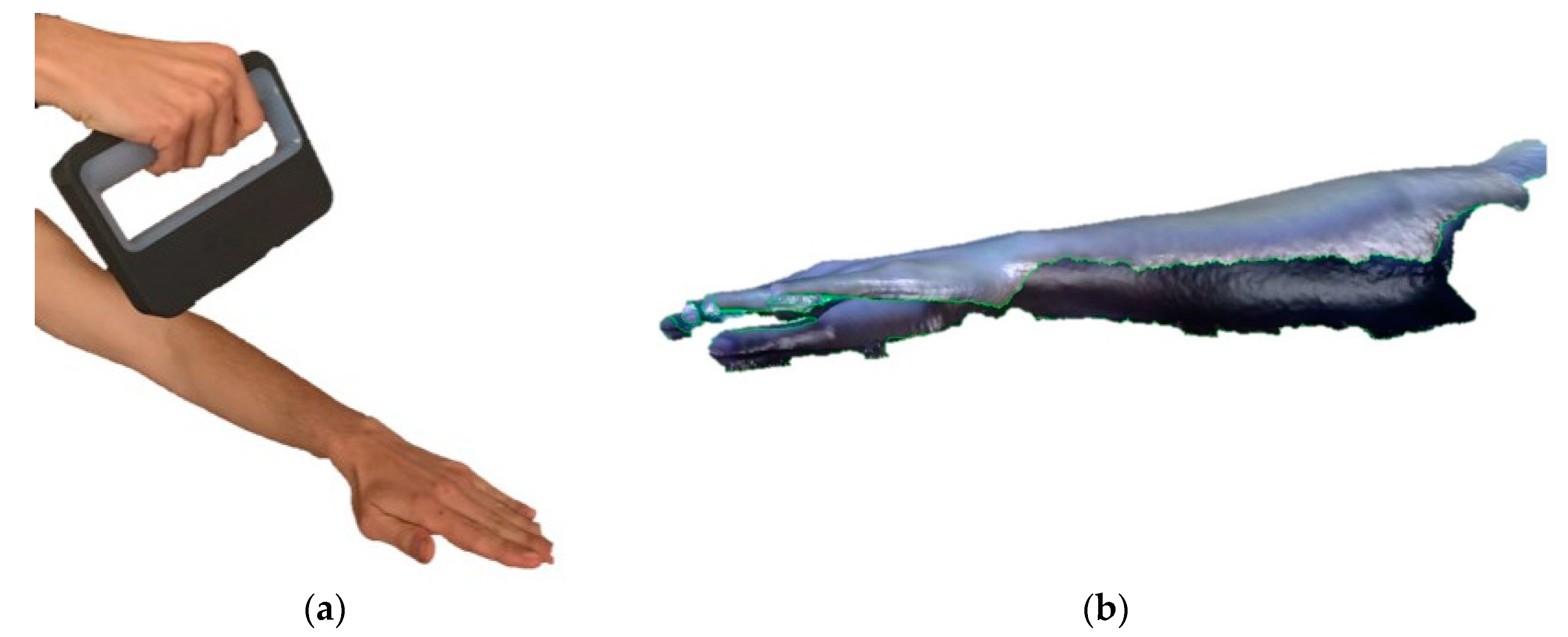
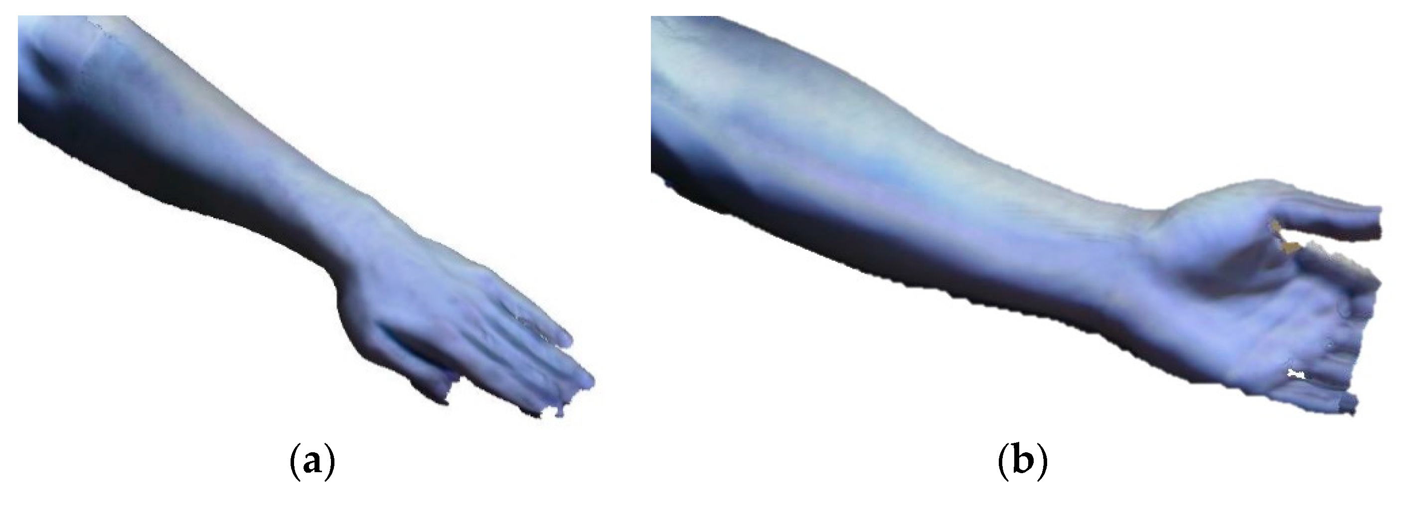
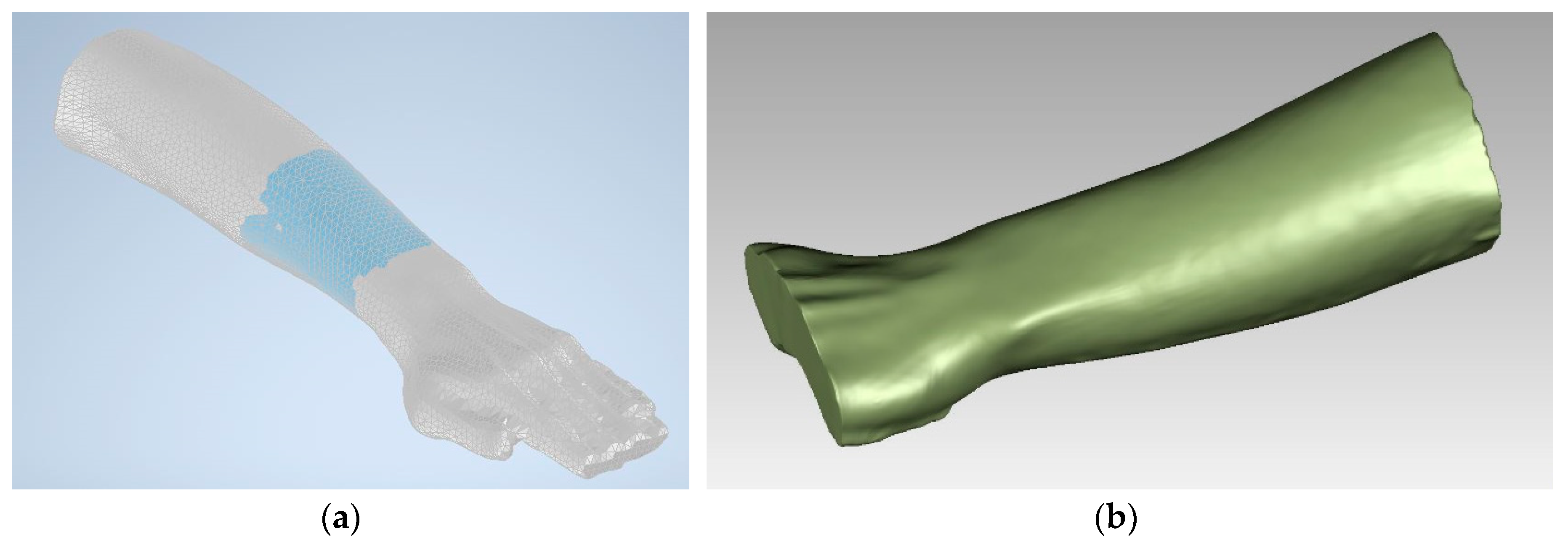
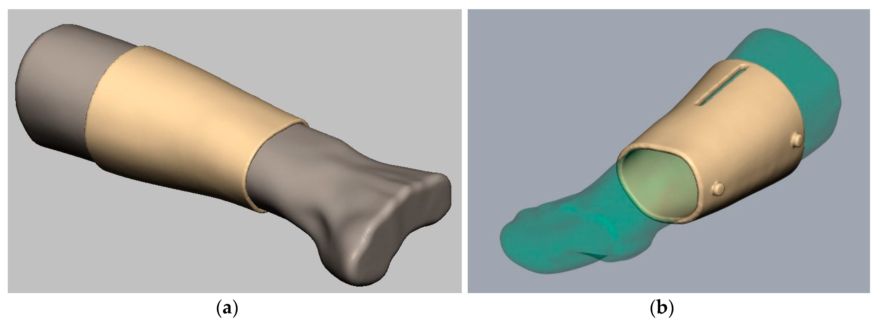
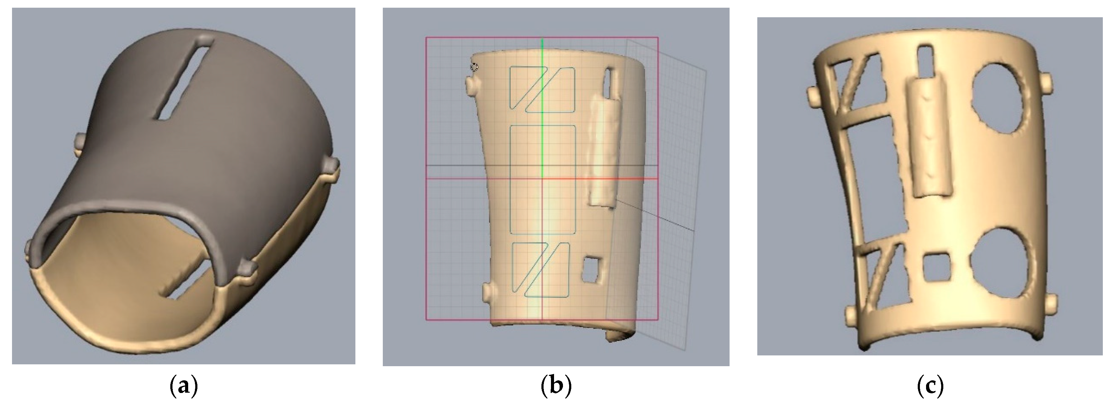
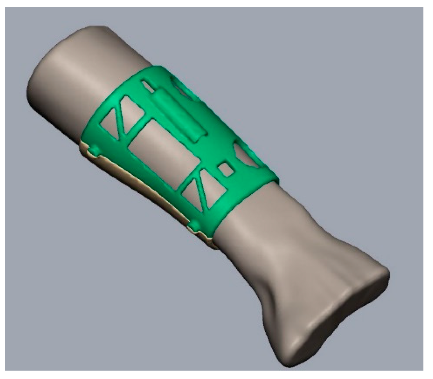
2.1. 3D Model and Design
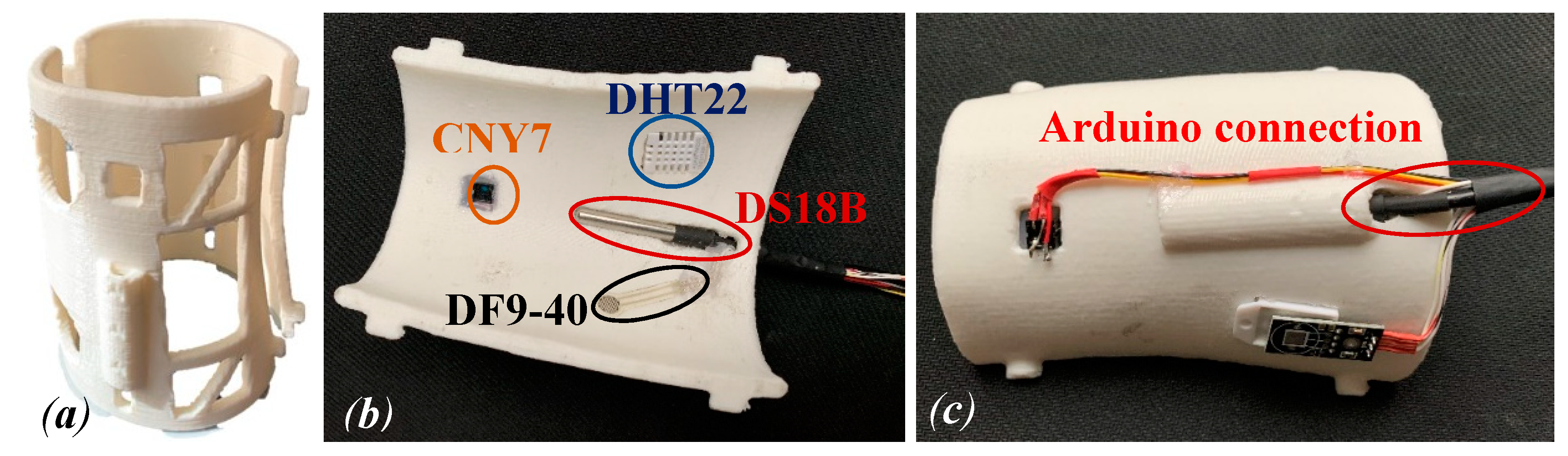
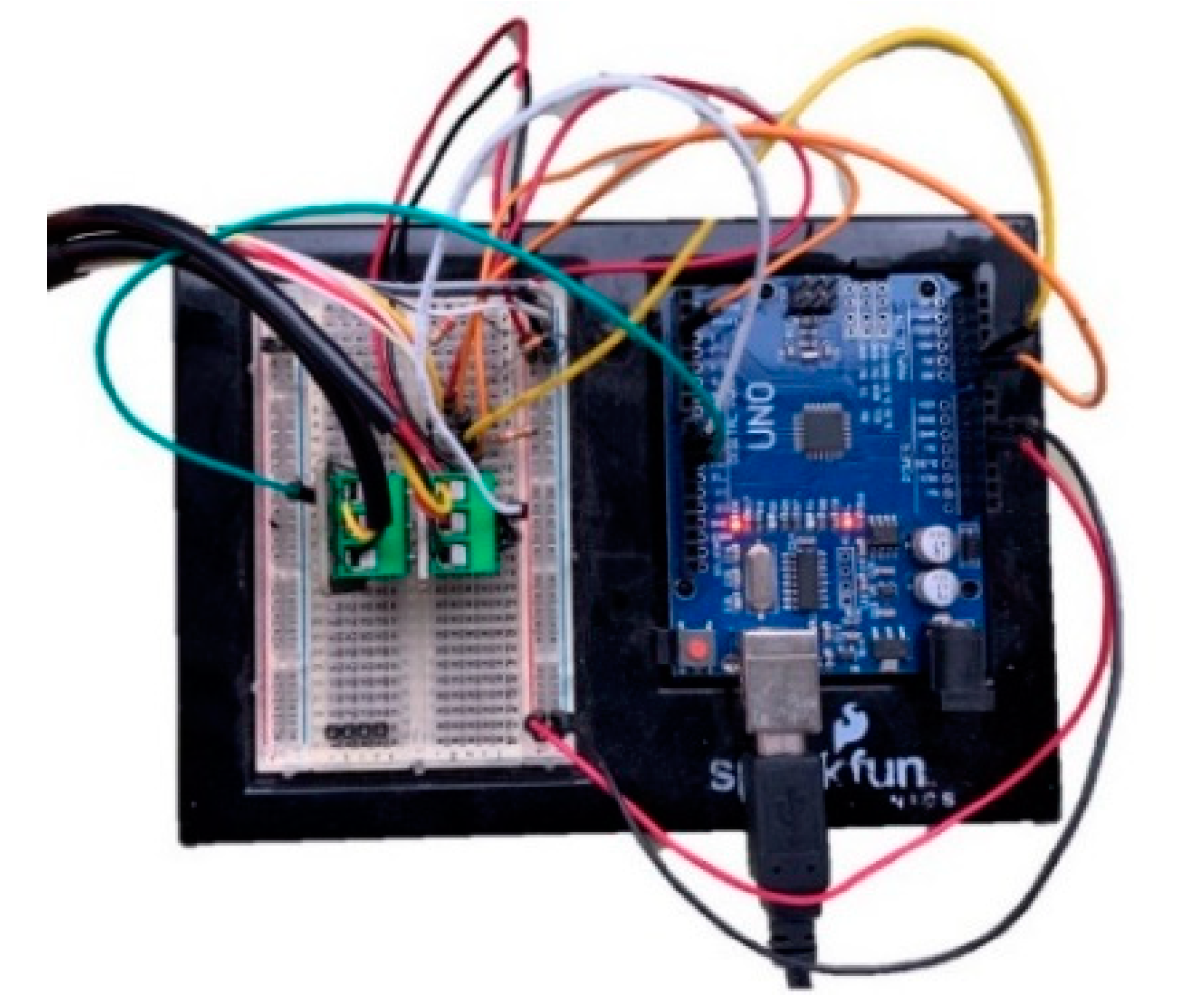
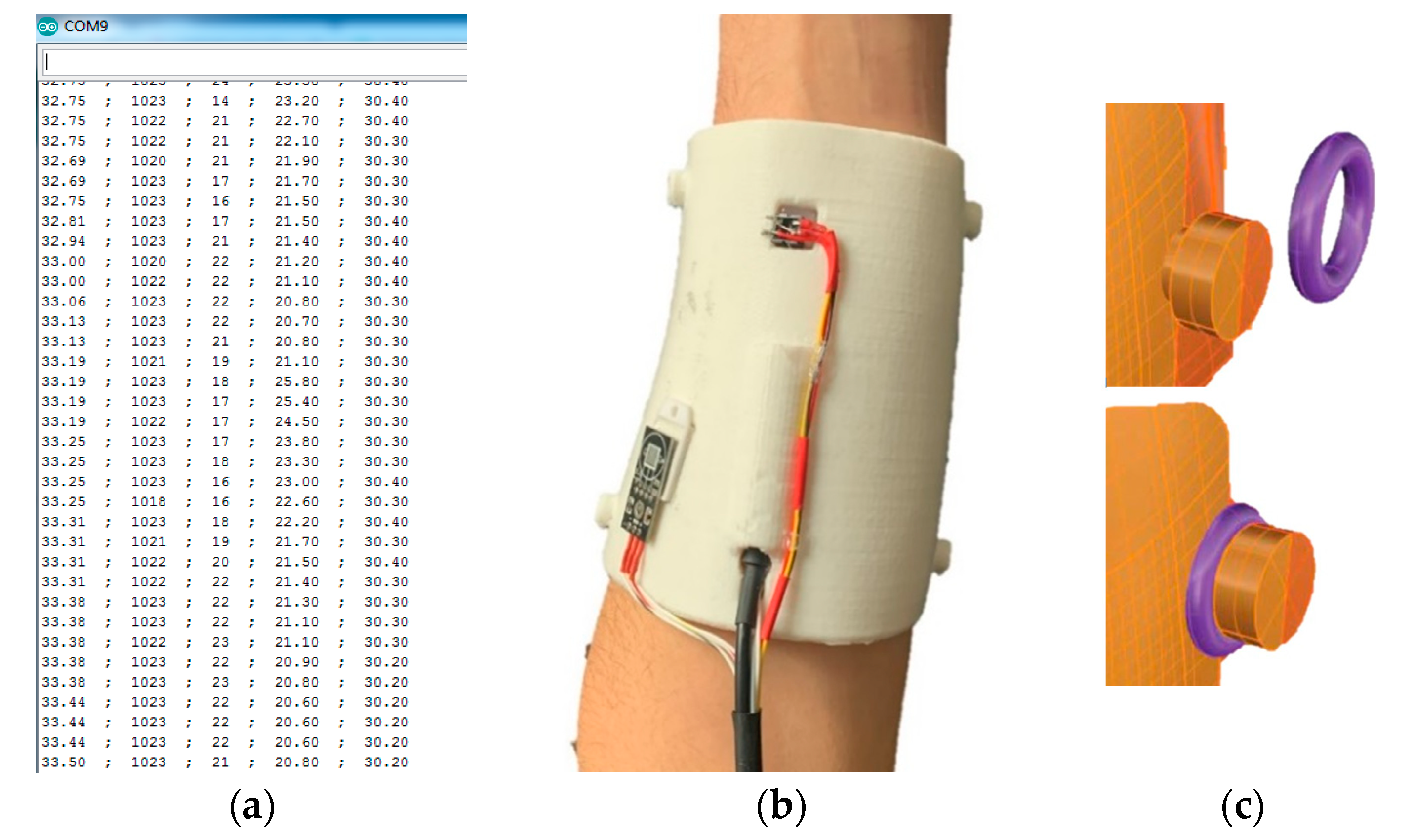
2.2. Sensing Technologies
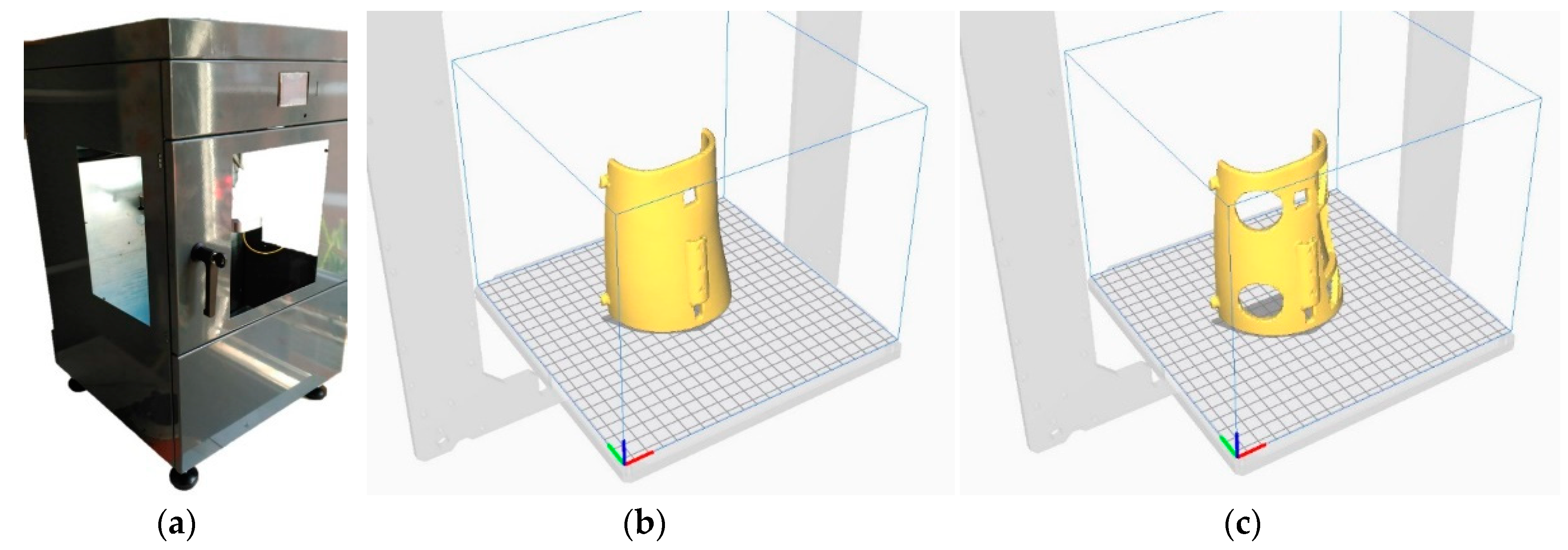
2.3. Additive Manufacturing
3. Results
3.1. 3D Model and Design
3.2. Sensing Technologies
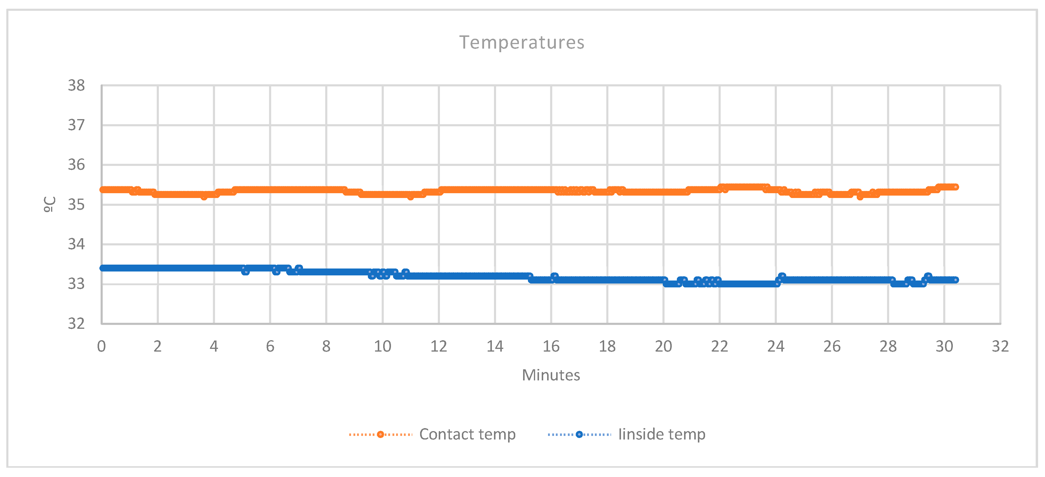
3.2.1. Temperatures
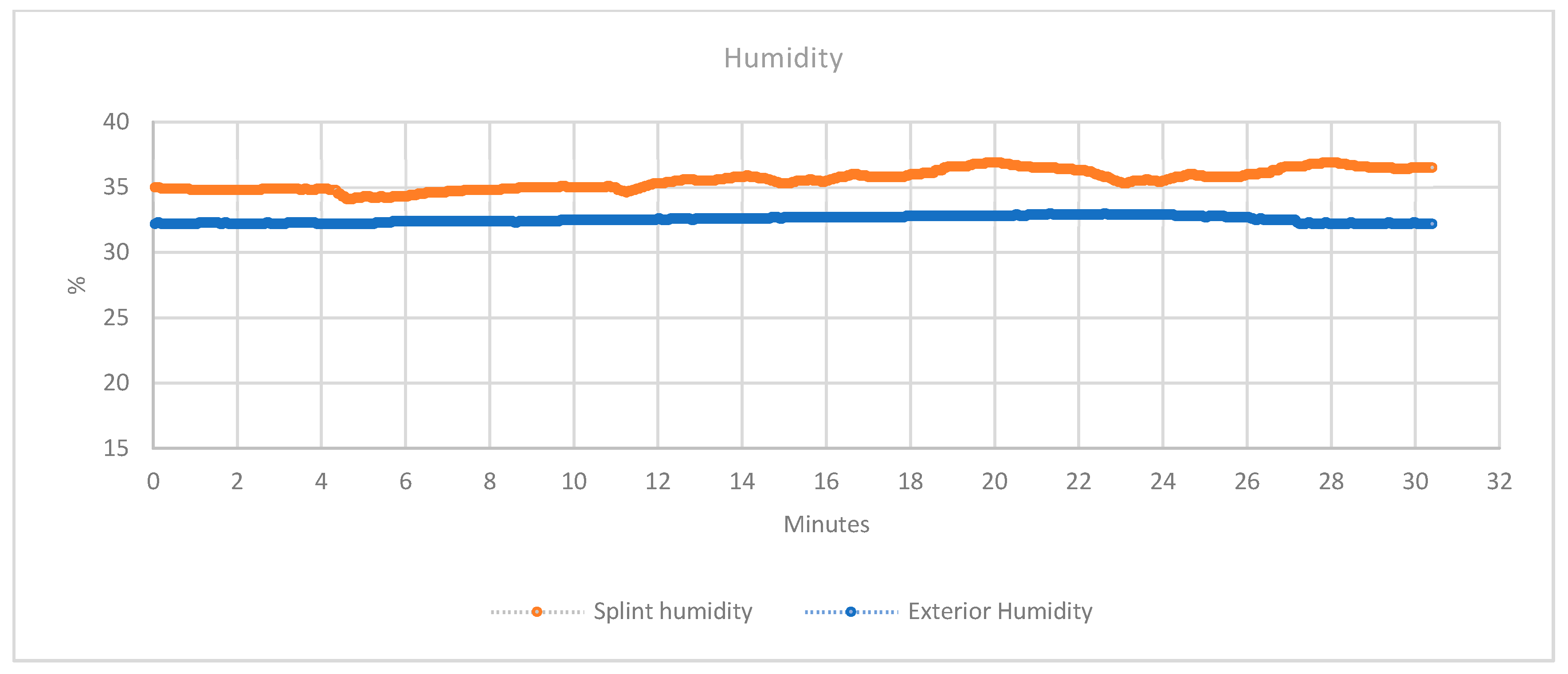
3.2.2. Humidity
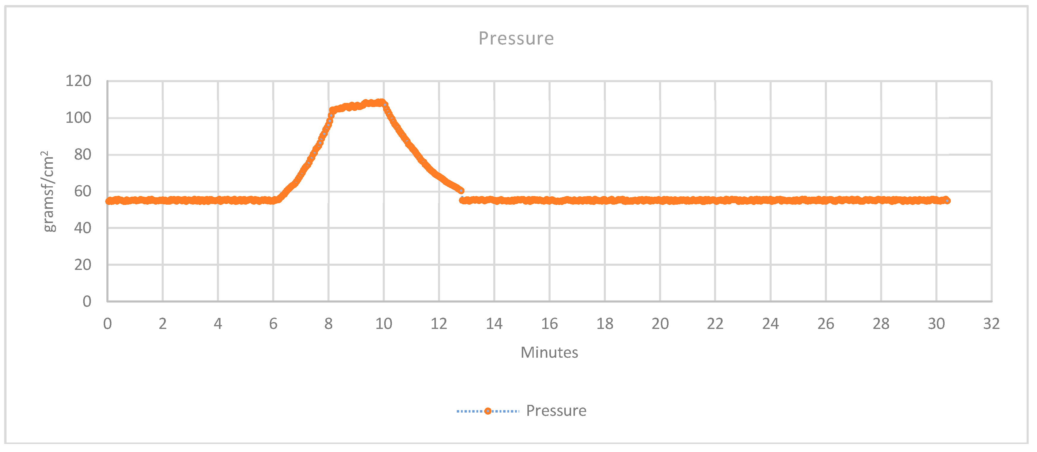
3.2.3. Pressure
4. Discussions
5. Conclusions
- Implementation of a sensor to detect color changes of the skin: This would make it possible to detect bruising and redness, which would allow to get more data for the diagnostic.
- Sending these data to a Bluetooth device that allows remote medical monitoring of the treatment applied and the application of an alarm system in the event of complications, as well as the generation of the data dump in a database for study.
- Integration into functional splints based on rehabilitation techniques in the immobilization phase. This would make it necessary to incorporate a battery to get a full autonomous system.
Author Contributions
Funding
Conflicts of Interest
References
- Jammalamadaka, U.; Tappa, K. Recent advances in biomaterials for 3D printing and tissue engineering. J. Funct. Biomater. 2018, 9, 22. [Google Scholar] [CrossRef] [Green Version]
- Tappa, K.; Jammalamadaka, U. Novel biomaterials used in medical 3D printing techniques. J. Funct. Biomater. 2018, 9, 17. [Google Scholar] [CrossRef] [Green Version]
- Bandyopadhyay, A.; Bose, S.; Das, S. 3D printing of biomaterials. MRS Bull. 2015. [Google Scholar] [CrossRef] [Green Version]
- Chia, H.N.; Wu, B.M. Recent advances in 3D printing of biomaterials. J. Biol. Eng. 2015, 9, 1–14. [Google Scholar] [CrossRef] [Green Version]
- Guvendiren, M.; Molde, J.; Soares, R.M.D.; Kohn, J. Designing Biomaterials for 3D Printing. ACS Biomater. Sci. Eng. 2016, 2, 1679–1693. [Google Scholar] [CrossRef] [PubMed]
- Valášek, P.; D’Amato, R.; Müller, M.; Ruggiero, A. Musa textilis Cellulose Fibres in Biocomposites—An Investigation of Mechanical Properties and Microstructure. BioResources 2018, 13, 3177–3194. [Google Scholar] [CrossRef]
- Blaya, F.; Pedro, P.S.; Silva, J.L.; D’Amato, R.; Heras, E.S.; Juanes, J.A. Design of an Orthopedic Product by Using Additive Manufacturing Technology: The Arm Splint. J. Med. Syst. 2018, 42. [Google Scholar] [CrossRef] [PubMed]
- Affatato, S.; Ruggiero, A.; De Mattia, J.S.; Taddei, P. Does metal transfer affect the tribological behaviour of femoral heads? Roughness and phase transformation analyses on retrieved zirconia and Biolox® Delta composites. Compos. Part B Eng. 2016, 92, 290–298. [Google Scholar] [CrossRef]
- Lozano, M.T.U.; D’Amato, R.; Ruggiero, A.; Manzoor, S.; Haro, F.B.; Méndez, J.A.J. A study evaluating the level of satisfaction of the students of health sciences about the use of 3D printed bone models. In Proceedings of the Sixth International Conference on Technological Ecosystems for Enhancing Multiculturality-TEEM’18, Salamanca, Spain, 24–26 October 2018. [Google Scholar]
- Ugidos Lozano, M.T.; Blaya Haro, F.; Ruggiero, A.; Manzoor, S.; Nuere Menendez-Pidal, S.; Juanes Méndez, J.A. Different Digitalization Techniques for 3D Printing of Anatomical Pieces. J. Med. Syst. 2018, 42, 46. [Google Scholar] [CrossRef] [PubMed]
- Ghai, S.; Sharma, Y.; Jain, N.; Satpathy, M.; Pillai, A.K. Use of 3-D printing technologies in craniomaxillofacial surgery: A review. Oral Maxillofac. Surg. 2018, 22, 249–259. [Google Scholar] [CrossRef] [PubMed]
- García, N.M.; Blaya, F.; Urquijo, E.L.; Heras, E.S.; D’Amato, R. Oral appliance for Obstructive Sleep Apnea: Prototyping and Optimization of the Mandibular Protrusion Device. J. Med. Syst. 2019, 43, 107. [Google Scholar] [CrossRef] [PubMed]
- Montesdeoca, N.; Lechosa, E.; Haro, F.B.; D’Amato, R.; Juanes, J.A. Design of thermoplastic oral appliance with mouth opening control to treat obstructive sleep apnea. In Proceedings of the ACM International Conference Proceeding Series; Association for Computing Machinery: New York, NY, USA, 2019; pp. 404–410. [Google Scholar]
- Mulford, J.S.; Babazadeh, S.; Mackay, N. Three-dimensional printing in orthopaedic surgery: Review of current and future applications. ANZ J. Surg. 2016, 86, 648–653. [Google Scholar] [CrossRef] [PubMed] [Green Version]
- Lunsford, C.; Grindle, G.; Salatin, B.; Dicianno, B.E. Innovations With 3-Dimensional Printing in Physical Medicine and Rehabilitation: A Review of the Literature. PM R 2016, 8, 1201–1212. [Google Scholar] [CrossRef] [PubMed]
- Fitzpatrick, A.P. Design of a Patient Specific, 3D printed Arm Cast. KnE Eng. 2017, 2, 135. [Google Scholar] [CrossRef]
- Cernohorsky, J.; Cadek, M. Smart rehabilitation splint. In Advances in Mechanism Design II; Springer: Cham, Switzerland, 2017. [Google Scholar]
- Evill, J.; Evill, O. Cortex Evill. Available online: https://www.evilldesign.com/cortex (accessed on 8 April 2020).
- Robin, O.; Claude, A.; Gehin, C.; Massot, B.; McAdams, E. Recording of bruxism events in sleeping humans at home with a smart instrumented splint. J. Craniomandib. Sleep Pract. 2020. [Google Scholar] [CrossRef]
- Goncu-Berk, G.; Topcuoglu, N. A Healthcare Wearable for Chronic Pain Management. Design of a Smart Glove for Rheumatoid Arthritis. Des. J. 2017, 20, S1978–S1988. [Google Scholar] [CrossRef]
- Chiu, Y.H.; Chen, T.W.; Chen, Y.J.; Su, C.I.; Hwang, K.S.; Ho, W.H. Fuzzy logic-based mobile computing system for hand rehabilitation after neurological injury. Technol. Health Care 2018, 26, 17–27. [Google Scholar] [CrossRef]
- Dimitrov, D.V. Medical internet of things and big data in healthcare. Healthc. Inf. Res. 2016, 22, 156–163. [Google Scholar] [CrossRef]
- Yin, Y.; Zeng, Y.; Chen, X.; Fan, Y. The internet of things in healthcare: An overview. J. Ind. Inf. Integr. 2016, 1, 3–13. [Google Scholar] [CrossRef]
- Zanella, A.; Bui, N.; Castellani, A.; Vangelista, L.; Zorzi, M. Internet of things for smart cities. IEEE Internet Things J. 2014, 1, 22–32. [Google Scholar] [CrossRef]
- Fan, Y.J.; Yin, Y.H.; Xu, L.D.; Zeng, Y.; Wu, F. IoT-based smart rehabilitation system. IEEE Trans. Ind. Inform. 2014, 10, 1568–1577. [Google Scholar] [CrossRef]
- Blaya, F.; Pedro, P.S.; Pedro, A.B.S.; Lopez-Silva, J.; Juanes, J.A.; D’Amato, R. Design of a Functional Splint for Rehabilitation of Achilles Tendon Injury Using Advanced Manufacturing (AM) Techniques. Implementation Study. J. Med. Syst. 2019, 43, 122. [Google Scholar] [CrossRef] [PubMed]
- Ju, X.; Nebel, J.-C.; Siebert, J.P. 3D thermography imaging standardization technique for inflammation diagnosis. In Proceedings of the Infrared Components and Their Applications; Gong, H., Cai, Y., Chatard, J.-P., Eds.; SPIE: Bellingham, WA, USA, 2005. [Google Scholar]
- Schlereth, T.; Drummond, P.D.; Birklein, F. Inflammation in CRPS: Role of the sympathetic supply. Auton. Neurosci. Basic Clin. 2014, 182, 102–107. [Google Scholar] [CrossRef] [PubMed] [Green Version]
- Dallas Semiconductor. Programmable Resolution 1-Wire® Digital Thermometer; Dallas Semiconductor: Dallas, TX, USA, 2002. [Google Scholar]
- Liu, T. Digital-Output Relative Humidity & Temperature Sensor/Module DHT22 (DHT22 Also Named as AM2302); Aosong Electronics Co.: Guangzhou, China, 2015. [Google Scholar]
- Datasheet Film Pressure Sensor DF9-40@10kg V2.0. Available online: https://www.winsen-sensor.com/d/files/df9-40%4010kg.pdf (accessed on 2 May 2020).
- Reflective Optical Sensor with Transistor Output. Available online: https://www.tme.eu/Document/5c845fc67f29d9b4e8f31810ed773b0f/cny70.pdf (accessed on 2 May 2020).
- Arduino Arduino Uno Rev3|Arduino Official Store. Available online: https://store.arduino.cc/arduino-uno-rev3 (accessed on 19 April 2020).
- Haro, F.B.; de Agustín del Burgo, J.M.; D’Amato, R.; Islán, M.; Heras, E.S.; Alonso, J.M.G.; Mendez, J.A.J. Monitoring an Analysis of Perturbations in Fusion Deposition Modelling (FDM) Processes for the Use of Biomaterials. J. Med. Syst. 2019, 43, 109. [Google Scholar] [CrossRef]
- Haro, F.B.; de Agustín del Burgo, J.M.; D’Amato, R.; Marcos, M.I.; Heras, E.; Alonso, J.M.G. Monitoring of the additive manufacturing process for the use of biomaterials in medical field. In Proceedings of the Sixth International Conference on Technological Ecosystems for Enhancing Multiculturality-TEEM’18, Salamanca, Spain, 24–26 October 2018; ACM Press: New York, NY, USA, 2018; pp. 428–432. [Google Scholar]
- Soriano Heras, E.; Blaya Haro, F.; de Agustín del Burgo, J.M.; Islán Marcos, M.; D’Amato, R. Filament advance detection sensor for fused deposition modelling 3D printers. Sensors 2018, 18, 1495. [Google Scholar] [CrossRef] [Green Version]
- Del Burgo, J.M.D.A.; D’Amato, R.; Méndez, J.A.J.; Ramírez, A.S.; Haro, F.B.; Heras, E.S. Real time analysis of the filament for FDM 3D printers. In ACM International Conference Proceeding Series; ACM Press: New York, NY, USA, 2019. [Google Scholar]
- Lawson, R. Implications of surface temperatures in the diagnosis of breast cancer. Can. Med. Assoc. J. 1956, 75, 309–311. [Google Scholar] [PubMed]
- Ströberg, B. The Use of Thermography in Equine Orthopedics. Vet. Radiol. 1974, 15, 94–97. [Google Scholar] [CrossRef]
- Wang, L.; Guo, T.Z.; Wei, T.; Li, W.W.; Shi, X.; Clark, J.D.; Kingery, W.S. Bisphosphonates Inhibit Pain, Bone Loss, and Inflammation in a Rat Tibia Fracture Model of Complex Regional Pain Syndrome. Anesthesia Analg. 2016, 123, 1033–1045. [Google Scholar] [CrossRef] [Green Version]
- Rundle, C.H.; Wang, H.; Yu, H.; Chadwick, R.B.; Davis, E.I.; Wergedal, J.E.; Lau, K.H.W.; Mohan, S.; Ryaby, J.T.; Baylink, D.J. Microarray analysis of gene expression during the inflammation and endochondral bone formation stages of rat femur fracture repair. Bone 2006, 38, 521–529. [Google Scholar] [CrossRef]


| Maximum Scan Volume | 2 × 2 × 2 (m) |
| Minimum Scan Volume | 0.2 × 0.2 × 0.2 (m) |
| Working Distance | 0.2–1.6 (m) |
| Number of Cameras | 2 |
| Class Certified Laser Product | 1 |
| Resolution at 0.5 m | 1 (mm) |
| Sensor Serial Number | DS18B20 | DHT22 | DF9-40 | CNY70 |
|---|---|---|---|---|
| Dimensions (mm) | 6 × 6 × 50 | 15 × 7.7 × 20 | 40 × 20 × 0.25 | 7 × 7 × 6 |
| Power voltage (V) | 3.0–5.5 | 3.3–6 | 5 | 5 |
| Working range | −55 °C to 125 °C | −40 °C to 80 °C 0 to 100% RH | 0–500 g | 0 to 10 mm |
| Resolution | ± 0.0625 °C | 0.1 °C 0.1% RH | 14.5 g | − |
| Layer height [mm] | 0.2 |
| Extruder [mm] | 0.4 |
| Print density [%] | 40 |
| Thickness perimeter of closure of each layer [mm] | 1 |
| Print speed [mm/s] | 60 |
| Temperature [°C] | 210 |
© 2020 by the authors. Licensee MDPI, Basel, Switzerland. This article is an open access article distributed under the terms and conditions of the Creative Commons Attribution (CC BY) license (http://creativecommons.org/licenses/by/4.0/).
Share and Cite
De Agustín Del Burgo, J.M.; Blaya Haro, F.; D’Amato, R.; Juanes Méndez, J.A. Development of a Smart Splint to Monitor Different Parameters during the Treatment Process. Sensors 2020, 20, 4207. https://0-doi-org.brum.beds.ac.uk/10.3390/s20154207
De Agustín Del Burgo JM, Blaya Haro F, D’Amato R, Juanes Méndez JA. Development of a Smart Splint to Monitor Different Parameters during the Treatment Process. Sensors. 2020; 20(15):4207. https://0-doi-org.brum.beds.ac.uk/10.3390/s20154207
Chicago/Turabian StyleDe Agustín Del Burgo, José María, Fernando Blaya Haro, Roberto D’Amato, and Juan Antonio Juanes Méndez. 2020. "Development of a Smart Splint to Monitor Different Parameters during the Treatment Process" Sensors 20, no. 15: 4207. https://0-doi-org.brum.beds.ac.uk/10.3390/s20154207