
Design and Performance Analysis of a Compact Planar MIMO Antenna for IoT Applications

 , , , and
Abstract
:1. Introduction
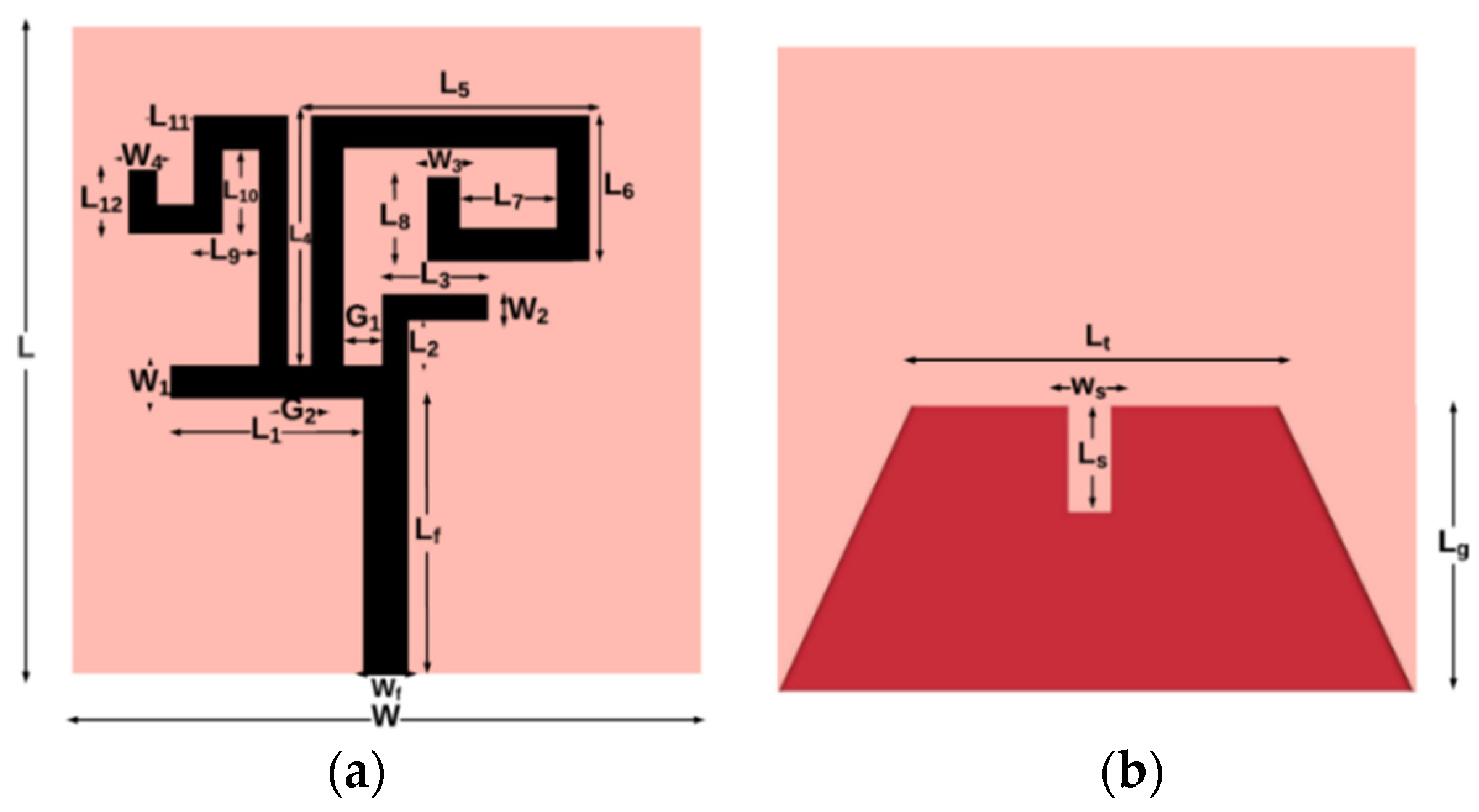
2. Antenna Design
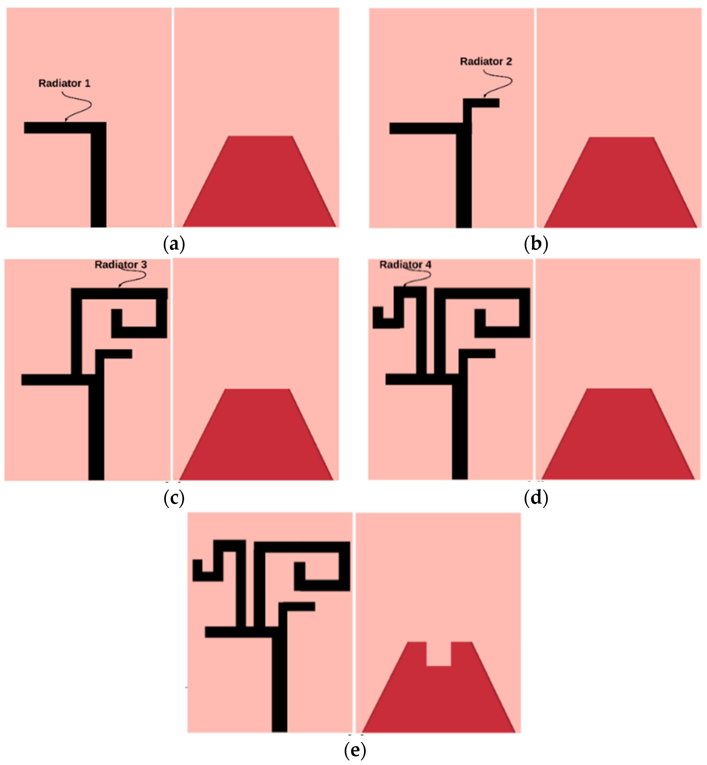
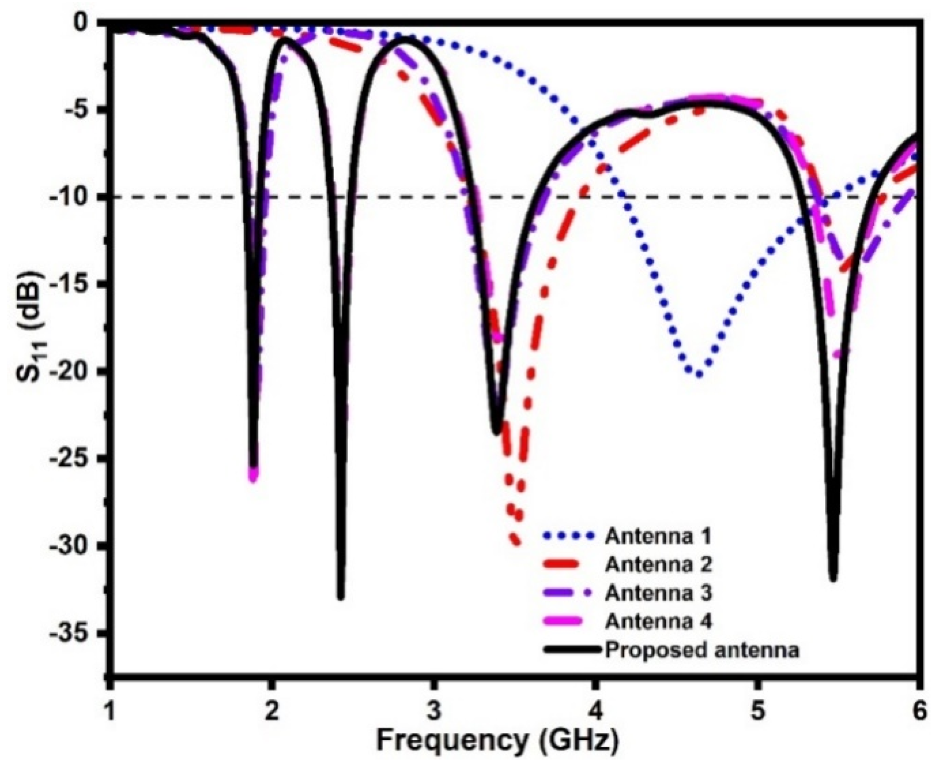
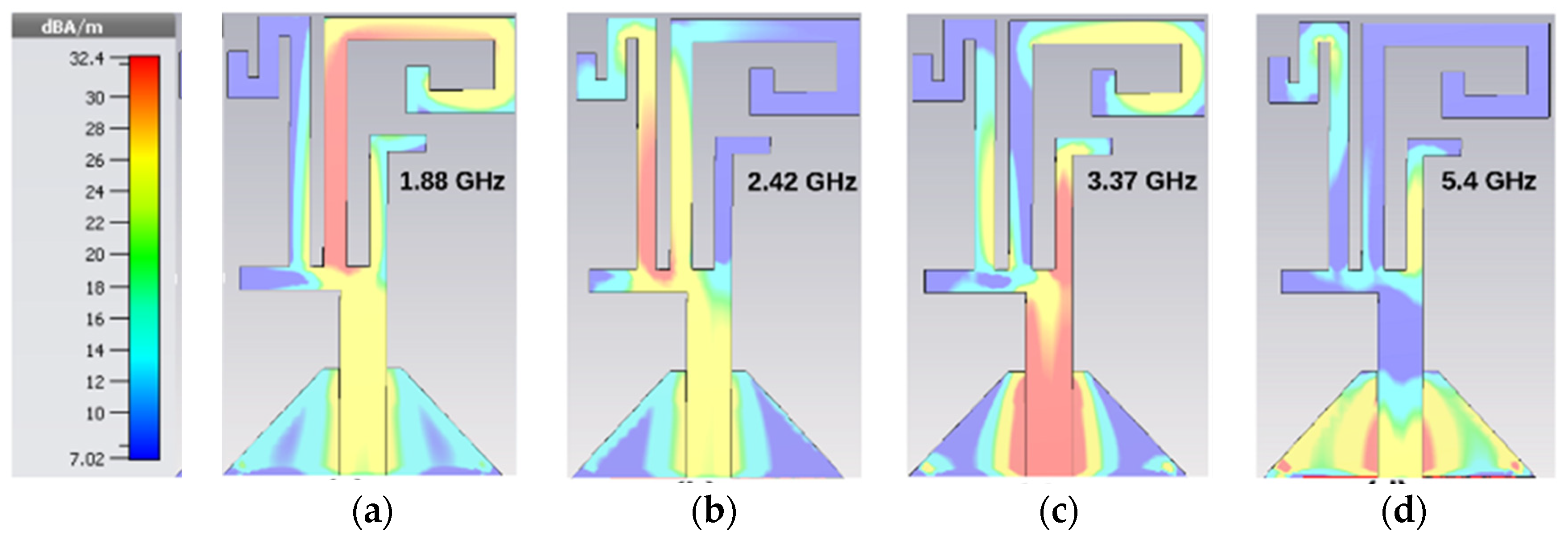
2.1. Evolution of the Antenna Element
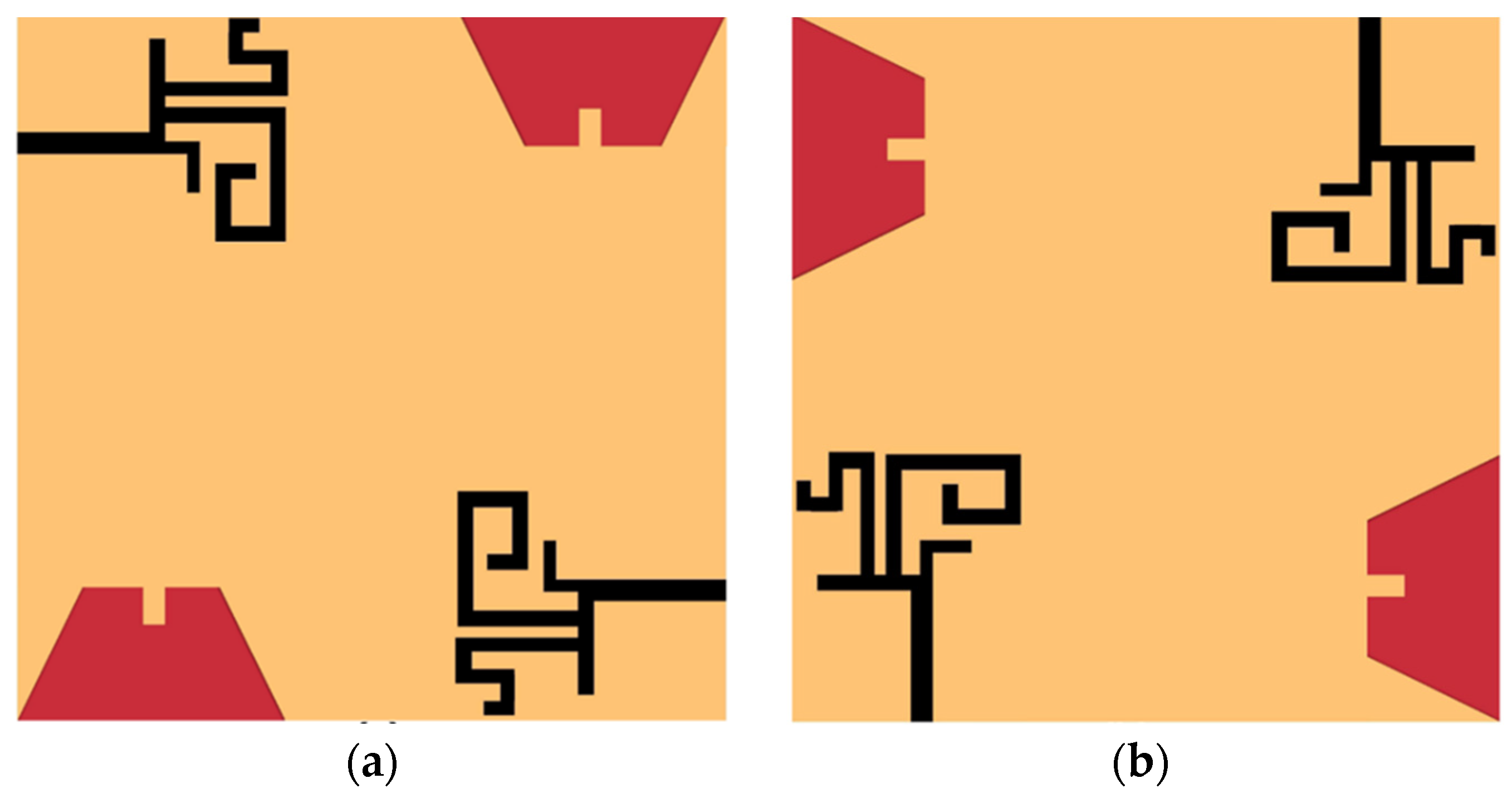
2.2. MIMO Implementation
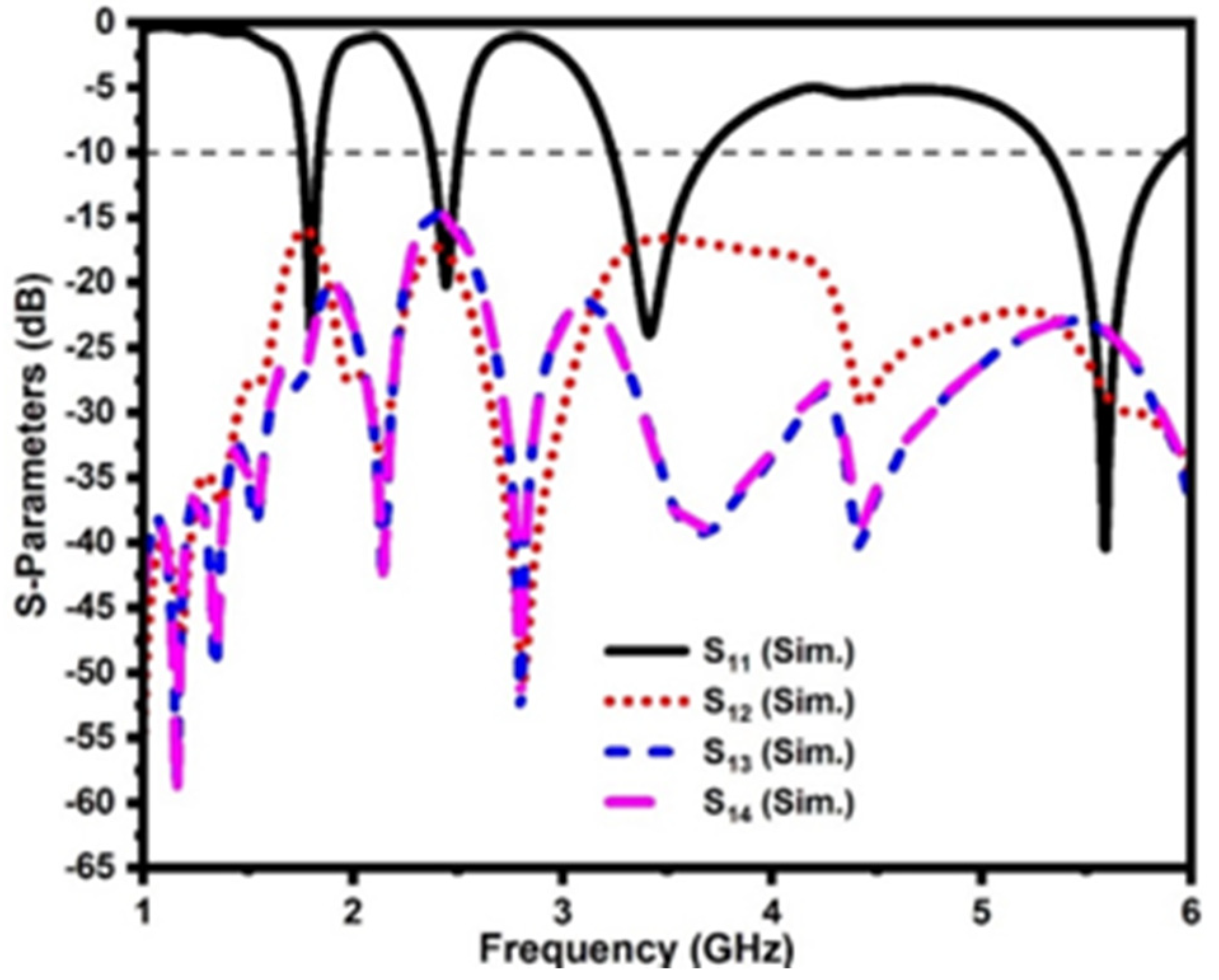
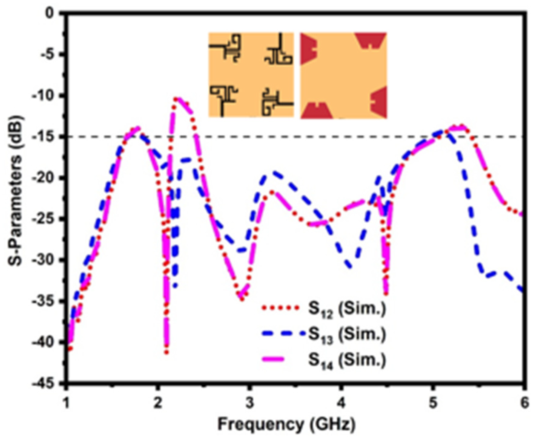
3. Results and Discussion
3.1. ECC
3.2. DG
3.3. MEG
3.4. TARC
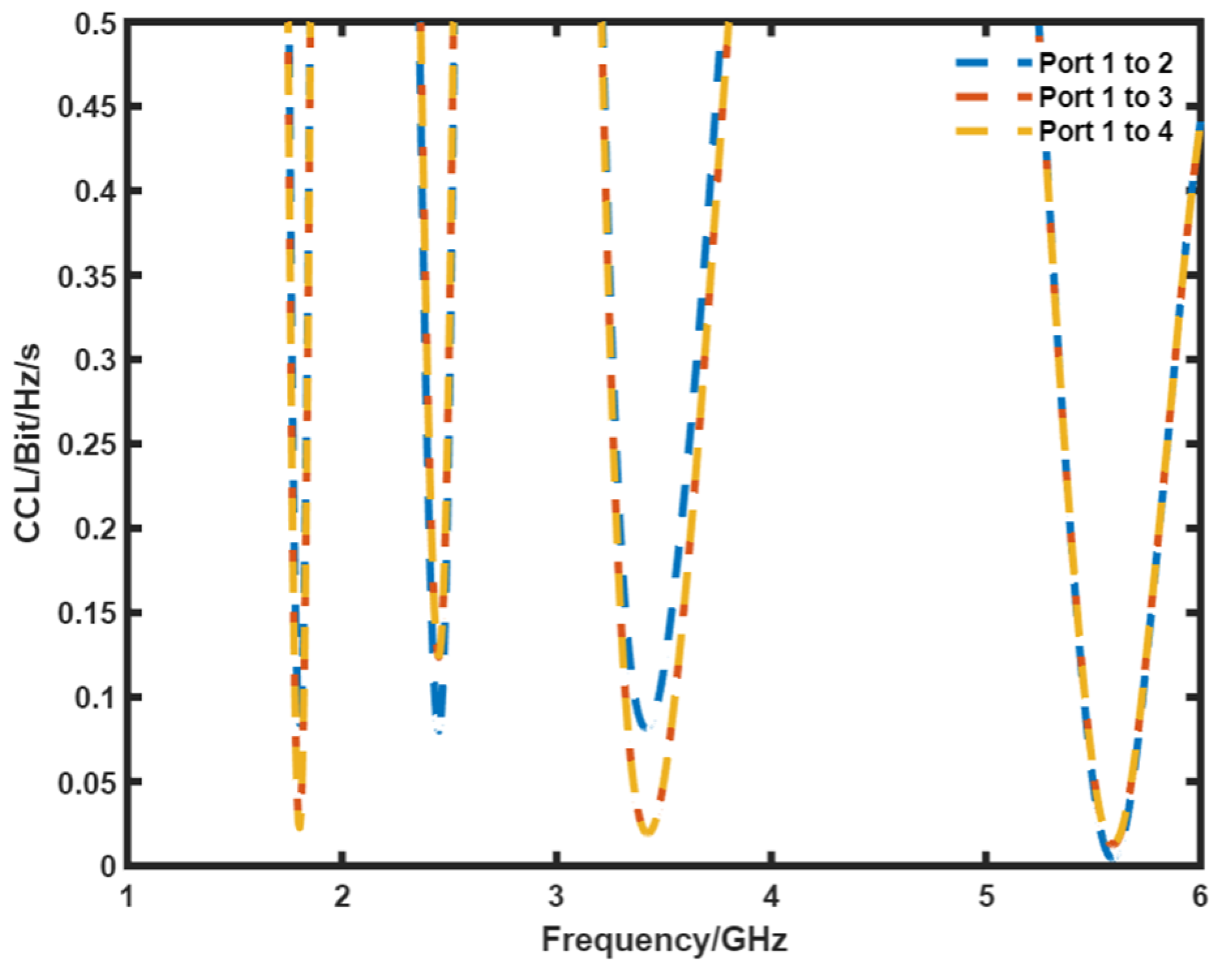
3.5. CCL
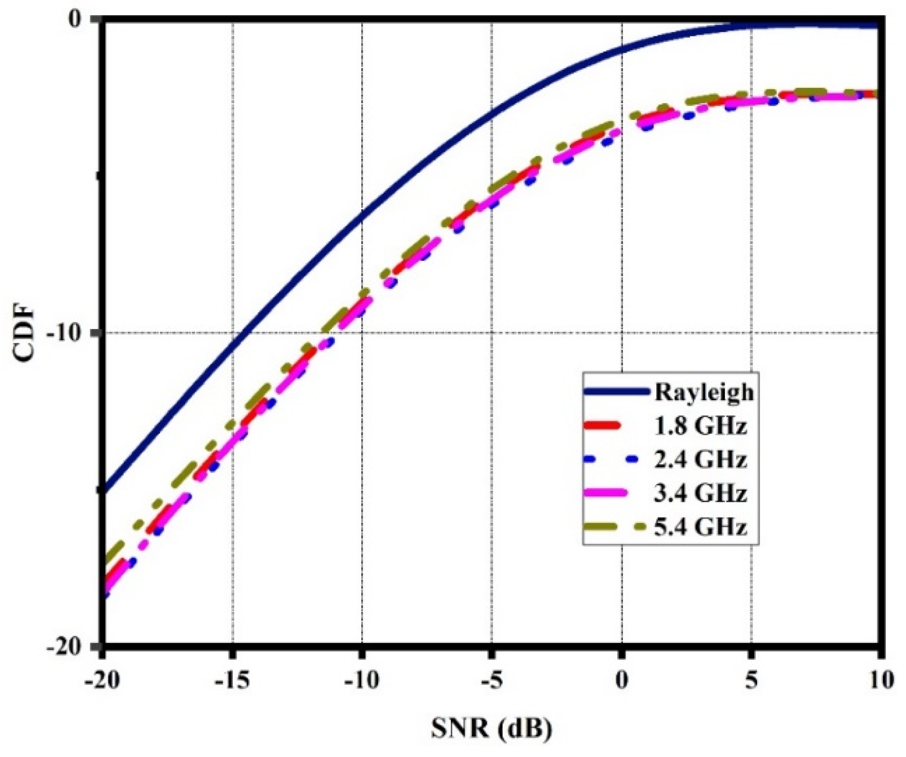
3.6. CDF
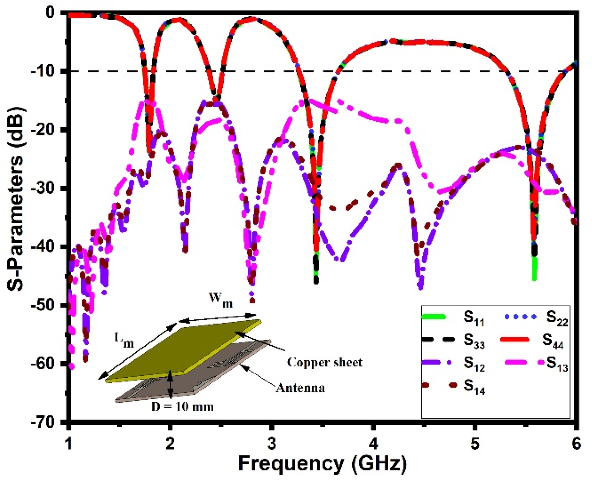
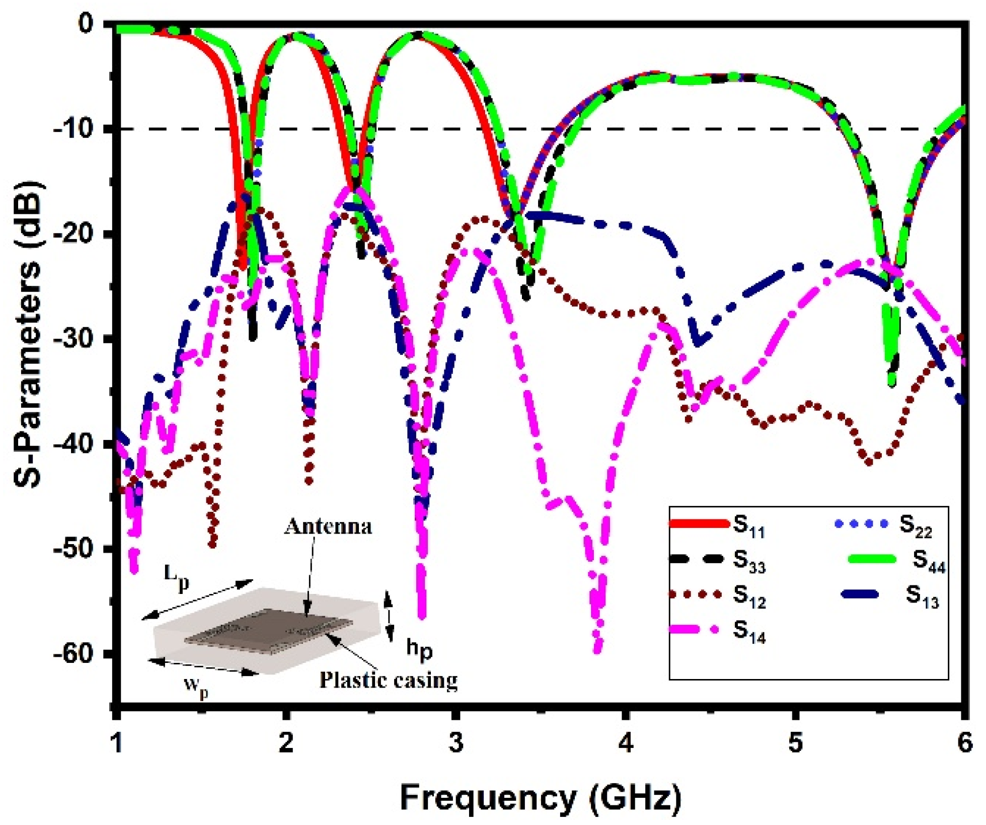
3.7. Housing Effect
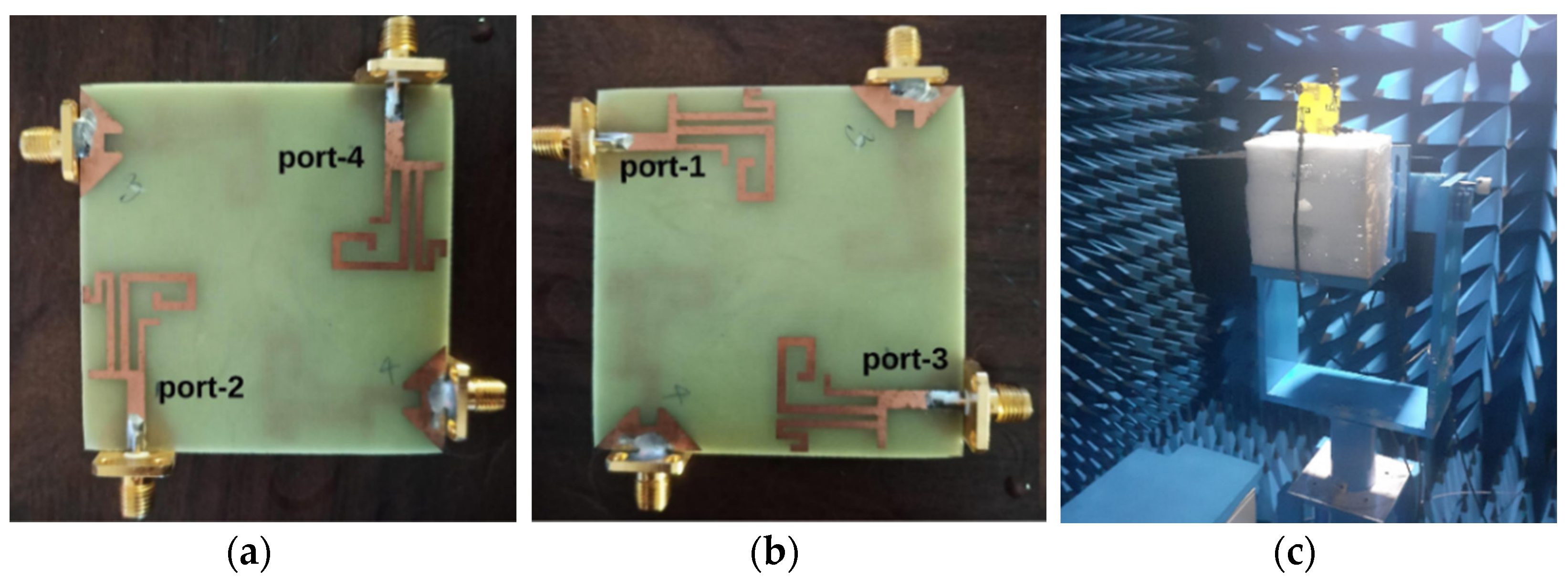
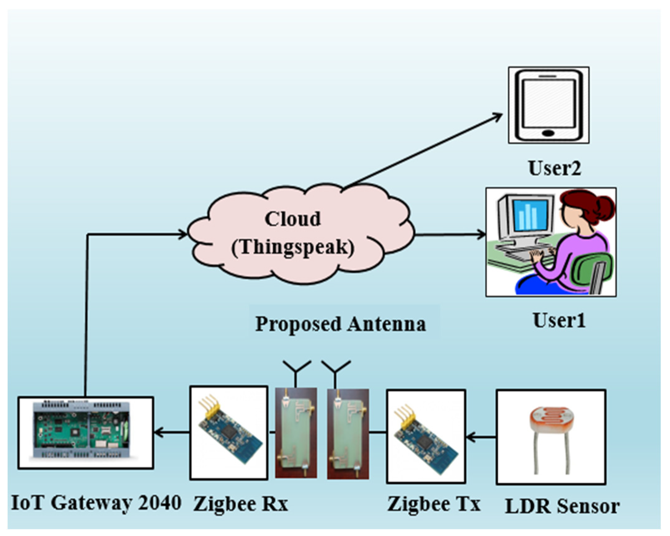
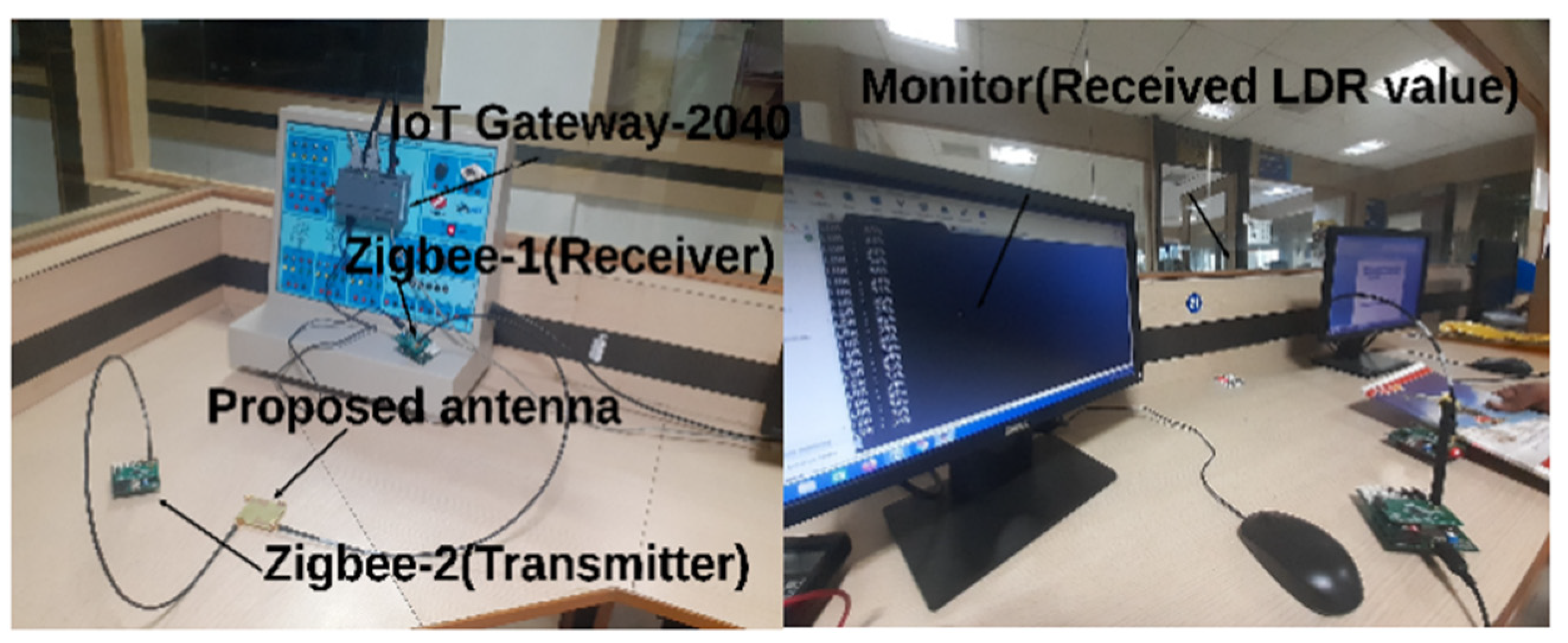
4. Real-Time Verification of the DS MIMO Antenna
5. Conclusions
Author Contributions
Funding
Institutional Review Board Statement
Informed Consent Statement
Data Availability Statement
Conflicts of Interest
References
- Jabbar, W.A.; Kian, T.K.; Ramli, R.M.; Zubir, S.N.; Zamrizaman, N.S.; Balfaqih, M.; Shepelev, V.; Alharbi, S. Design and fabrication of smart home with Internet of Things enabled automation system. IEEE Access 2019, 7, 144059–144074. [Google Scholar] [CrossRef]
- Kafle, V.P.; Fukushima, Y.; Harai, H. Internet of things standardization in ITU and prospective networking technologies. IEEE Commun. Mag. 2016, 54, 43–49. [Google Scholar] [CrossRef]
- Jhamb, K.; Li, L.; Rambabu, K. Novel-integrated patch antennas with multi-band characteristics. IET Microw. Antennas Propag. 2011, 5, 1393–1398. [Google Scholar] [CrossRef]
- Li, D.; Mao, J.F. A Koch-like sided fractal bow-tie dipole antenna. IEEE Trans. Antennas Propag. 2012, 60, 2242–2251. [Google Scholar] [CrossRef]
- Deshmukh, A.A.; Ray, K.P. Stub loaded multi-band slotted rectangular microstrip antennas. IET Microw. Antennas Propag. 2009, 33, 529–535. [Google Scholar] [CrossRef]
- Liu, H.; Liu, Y.; Wei, M.; Gong, S. Dual-broadband dielectric resonator antenna based on modified Sierpinski fractal geometry. Electron. Lett. 2015, 51, 806–808. [Google Scholar] [CrossRef]
- Sharma, S.K.; Mulchandani, J.D.; Gupta, D.; Chaudhary, R.K. Triple-band metamaterial-inspired antenna using FDTD technique for WLAN/WiMAX applications. Int. J. RF Microw. Comput.-Aided Eng. 2015, 25, 688–695. [Google Scholar] [CrossRef]
- Gupta, R.K.; Kumar, G. Printed dual band monopole antenna structures for WLAN applications. Microw. Opt. Technol. Lett. 2008, 50, 2483–2487. [Google Scholar] [CrossRef]
- Dehmas, M.; Azrar, A.; Mouhouche, F.; Djafri, K.; Challal, M. Compact dual band slotted triangular monopole antenna for RFID applications. Microw. Opt. Technol. Lett. 2018, 60, 432–436. [Google Scholar] [CrossRef]
- Gyasi, K.O.; Wen, G.; Inserra, D.; Huang, Y.; Li, J.; Ampoma, A.E.; Zhang, H. A compact broadband cross-shaped circularly polarized planar monopole antenna with a ground plane extension. IEEE Antennas Wirel. Propag. Lett. 2018, 17, 335–338. [Google Scholar] [CrossRef]
- Althuwayb, A.A.; Al-Hasan, M.A.; Kumar, A.; Chaturvedi, D. Design of half-mode substrate integrated cavity inspired dual-band antenna. Int. J. RF Microw. Comput.-Aided Eng. 2021, 31, e22520. [Google Scholar] [CrossRef]
- Awais, Q.; Chattha, H.T.; Jamil, M.; Jin, Y.; Tahir, F.A.; Rehman, M.U. A novel dual ultrawideband CPW-fed printed antenna for Internet of Things (IoT) applications. Wirel. Commun. Mob. Comput. 2018, 2018, 1–9. [Google Scholar] [CrossRef] [Green Version]
- Liu, G.; Liu, Y.; Gong, S. Compact tri-band wide-slot monopole antenna with dual-ring resonator for WLAN/WiMAX applications. Microw. Opt. Technol. Lett. 2016, 58, 1097–1101. [Google Scholar] [CrossRef]
- Singh Brar, R.; Saurav, K.; Sarkar, D.; Vaibhav Srivastava, K. A triple band circular polarized monopole antenna for GNSS/UMTS/LTE. Microw. Opt. Technol. Lett. 2017, 59, 298–304. [Google Scholar] [CrossRef]
- Jalali, A.R.; Ahamdi-Shokouh, J.; Emadian, S.R. Compact multiband monopole antenna for UMTS, WiMAX, and WLAN applications. Microw. Opt. Technol. Lett. 2016, 58, 844–847. [Google Scholar] [CrossRef]
- Kumar, A.; Jhanwar, D.; Sharma, M.M. A compact printed multistubs loaded resonator rectangular monopole antenna design for multiband wireless systems. Int. J. RF Microw. Comput.-Aided Eng. 2017, 27, e21147. [Google Scholar] [CrossRef]
- Deng, J.Y.; Liu, S.Y.; Sun, D.Q.; Guo, L.X.; Xue, S.B. Multiband antenna for mobile terminals. Int. J. RF Microw. Comput.-Aided Eng. 2019, 29, e21925. [Google Scholar] [CrossRef]
- Chandan. Truncated ground plane multiband monopole antenna for WLAN and WiMAX applications. IETE J. Res. 2020, 25, 1–6. [Google Scholar]
- Chung, M.A. A miniaturized triple band monopole antenna with a coupled branch strip for bandwidth enhancement for IoT applications. Microw. Opt. Technol. Lett. 2018, 60, 2336–2342. [Google Scholar] [CrossRef]
- Chen, A.; Sun, M.; Zhang, Z.; Fu, X. Planar monopole antenna with a parasitic shorted strip for multistandard handheld terminals. IEEE Access 2020, 8, 51647–51652. [Google Scholar] [CrossRef]
- Brar, R.S.; Saurav, K.; Sarkar, D.; Srivastava, K.V. A quad-band dual-polarized monopole antenna for GNSS/UMTS/WLAN/WiMAX applications. Microw. Opt. Technol. Lett. 2018, 60, 538–545. [Google Scholar] [CrossRef]
- Patel, R.; Upadhyaya, T.; Desai, A.; Palandoken, M. Low profile multiband meander antenna for LTE/WiMAX/WLAN and INSAT-C application. AEU-Int. J. Electron. Commun. 2019, 102, 90–98. [Google Scholar] [CrossRef]
- Asadpor, L.; Rezvani, M. Multiband microstrip MIMO antenna with CSRR loaded for GSM and LTE applications. Microw. Opt. Technol. Lett. 2018, 60, 3076–3080. [Google Scholar] [CrossRef]
- Jha, K.R.; Bukhari, B.; Singh, C.; Mishra, G.; Sharma, S.K. Compact planar multistandard MIMO antenna for IoT applications. IEEE Trans. Antennas Propag. 2018, 66, 3327–3336. [Google Scholar] [CrossRef]
- Kumari, T.; Das, G.; Sharma, A.; Gangwar, R.K. Design approach for dual element hybrid MIMO antenna arrangement for wideband applications. Int. J. RF Microw. Comput.-Aided Eng. 2019, 29, e21486. [Google Scholar] [CrossRef]
- Ramachandran, A.; Mathew, S.; Rajan, V.; Kesavath, V. A compact triband quad-element MIMO antenna using SRR ring for high isolation. IEEE Antennas Wirel. Propag. Lett. 2016, 16, 1409–1412. [Google Scholar] [CrossRef]
- Satam, V.; Nema, S. Six-element dual polarized high-gain MIMO antenna for multiband applications. Microw. Opt. Technol. Lett. 2020, 62, 217–225. [Google Scholar] [CrossRef]
- Wang, M.; Xu, B.; Li, Y.; Luo, Y.; Zou, H.; Yang, G. Multiband multiple-input multiple-output antenna with high isolation for future 5G smartphone applications. Int. J. RF Microw. Comput.-Aided Eng. 2019, 29, e21758. [Google Scholar] [CrossRef]
- Chattha, H.T. 4-port 2-element MIMO antenna for 5G portable applications. IEEE Access 2019, 7, 96516–96520. [Google Scholar] [CrossRef]
- Kumar, N.; Khanna, R. A compact multi-band multi-input multi-output antenna for 4G/5G and IoT devices using theory of characteristic modes. Int. J. RF Microw. Comput.-Aided Eng. 2020, 30, e22012. [Google Scholar] [CrossRef]
- Anuar, S.U.; Jamaluddin, M.H.; Din, J.; Kamardin, K.; Dahri, M.H.; Idris, I.H. Triple band MIMO dielectric resonator antenna for LTE applications. AEU-Int. J. Electron. Commun. 2020, 118, 153172. [Google Scholar] [CrossRef]
- Kumar, P.; Urooj, S.; Malibari, A. Design and implementation of quad-element super-wideband MIMO antenna for IoT applications. IEEE Access 2020, 8, 226697–226704. [Google Scholar] [CrossRef]
- Nagendra, R.; Swarnalatha, S. Design and performance of four port MIMO antenna for IOT applications. ICT Express 2021. [CrossRef]
- Palanisamy, P.; Subramani, M. Design of metallic via based octa-port UWB MIMO antenna for IoT applications. IETE J. Res. 2021, 12, 1–11. [Google Scholar] [CrossRef]
- Maurya, N.K.; Bhattacharya, R. Design of compact dual-polarized multiband MIMO antenna using near-field for IoT. AEU-Int. J. Electron. Commun. 2020, 117, 153091. [Google Scholar] [CrossRef]
- Sharma, D.; Kanaujia, B.K.; Kumar, S. Compact multi-standard planar MIMO antenna for IoT/WLAN/Sub-6 GHz/X-band applications. Wirel. Netw. 2021, 27, 2671–2689. [Google Scholar] [CrossRef]
- Sharawi, M.S. Printed multi-band MIMO antenna systems and their performance metrics [wireless corner]. IEEE Antennas Propag. Mag. 2013, 55, 218–232. [Google Scholar] [CrossRef]
- Khan, A.A.; Jamaluddin, M.H.; Nasir, J.; Khan, R.; Aqeel, S.; Saleem, J. Design of a dual-Band MIMO dielectric resonator antenna with pattern diversity for WiMAX and WLAN applications. Prog. Electromagn. Res. M 2016, 50, 65–73. [Google Scholar] [CrossRef] [Green Version]
- Kulkarni, J.; Desai, A.; Sim, C.Y. Two port CPW-fed MIMO antenna with wide bandwidth and high isolation for future wireless applications. Int. J. RF Microw. Comput.-Aided Eng. 2021, 13, e22700. [Google Scholar] [CrossRef]
- Srivastava, K.; Kumar, S.; Kanaujia, B.K.; Dwari, S.; Choi, H.C.; Kim, K.W. Compact eight-port MIMO/diversity antenna with band rejection characteristics. Int. J. RF Microw. Comput.-Aided Eng. 2020, 30, e22170. [Google Scholar] [CrossRef]
- Boologam, A.V.; Krishnan, K.; Palaniswamy, S.K.; Manimegalai, C.T.; Gauni, S. On the design and analysis of compact super-wideband quad element chiral MIMO array for high data rate applications. Electronics 2020, 9, 1995. [Google Scholar] [CrossRef]
- Bashir, U.; Jha, K.R.; Mishra, G.; Singh, G.; Sharma, S.K. Octahedron-shaped linearly polarized antenna for multistandard services including RFID and IoT. IEEE Trans. Antennas Propag. 2017, 65, 3364–3373. [Google Scholar] [CrossRef]


| Parameter | L | W | Lf | Wf | L1 | W1 | L2 | L3 | W2 | L4 | L5 | L6 | L7 |
| Value (mm) | 30 | 20 | 7 | 3 | 8.4 | 1.5 | 8.5 | 4.5 | 1 | 15 | 12.5 | 3.7 | 8 |
| Parameter | L8 | W3 | L9 | L10 | L11 | L12 | W4 | G1 | G2 | Lg | Ls | Ws | Lt |
| Value (mm) | 1.5 | 1.5 | 3.4 | 4.4 | 2.7 | 2.5 | 1.3 | 1.5 | 1 | 8 | 2 | 3 | 12 |
| Frequency (GHz) | Isolation (dB) | ECC12 | ECC13 | ECC14 | DG12 (dB) | DG13 (dB) | DG14 (dB) | MEG12 | MEG13 | MEG14 |
|---|---|---|---|---|---|---|---|---|---|---|
| 1.8 | >23 | <0.035 | <0.025 | <0.023 | 9.83 | 9.88 | 9.85 | 0.997 | 0.985 | 0.987 |
| 2.4 | >20 | <0.015 | <0.008 | <0.009 | 9.94 | 9.85 | 9.88 | 0.981 | 0.983 | 0.98 |
| 3.4 | >21 | <0.005 | <0.007 | <0.003 | 9.98 | 9.94 | 9.99 | 0.999 | 0.997 | 0.995 |
| 5.4 | >22 | <0.003 | <0.006 | <0.005 | 10 | 10 | 10 | 0.994 | 0.984 | 0.982 |
| Frequency (GHz) | TARC12 (dB) | TARC13 (dB) | TARC14 (dB) |
|---|---|---|---|
| 1.8 | −34 | −48 | −45 |
| 2.4 | −25 | −30 | −29 |
| 3.4 | −38 | −54 | −54 |
| 5.4 | −35 | −36 | −34 |
| Ref. | Operation | Antenna Size (L mm × W mm), (λL × λW) | Operating Bands (GHz) |
|---|---|---|---|
| [8] | Dual-band | 40 × 18, 0.32 × 0.14 | 2.4–2.5, 5.15–5.875 |
| [9] | Dual-band | 105 × 105, 0.30 × 0.30 | 0.860–0.960, 2.38–2.52 |
| [10] | Dual-band | 43 × 49, 0.33 × 0.38 | 2.26–2.52, 3.9–6.38 |
| [11] | Dual-band | 20 × 20, 0.57 × 0.57 | 8.5–9, 11–11.5 |
| [12] | Dual-band | 35 × 25, 0.13 × 0.09 | 1.1–2.7, 3.15–3.65 |
| [13] | Tri-band | 32 × 28, 0.24 × 0.21 | 2.29–2.88, 3.26–3.88, 4.17–6.07 |
| [14] | Tri-band | 45 × 65, 0.24 × 0.34 | 1.56–1.78, 1.96–2.16, 2.47–2.66 |
| [15] | Tri-band | 30 × 34, 0.19 × 0.21 | 1.9–2.1, 3.4–3.6, 5.15–5.35 |
| [16] | Tri-band | 30 × 24, 0.25 × 0.21 | 2.5–2.7, 3.3–3.6, 5.2–5.8 |
| [17] | Tri-band | 75 × 120, 0.23 × 0.36 | 0.9, 1.85, 2.4 |
| [18] | Tri-band | 36 × 29, 0.27 × 0.22 | 2.32–2.65, 3.21–3.34, 5.01–6.14 |
| [19] | Tri-band | 45 × 10, 0.34 × 0.07 | 2.3–2.69, 3.4–3.7, 5.15–5.85 |
| [20] | Tri-band | 40 × 18, 0.11 × 0.05 | 0.856–1.1, 1.7–2.0, 2.1–2.7 |
| [21] | Quad-band | 70 × 50, 0.32 × 0.23 | 1.43–1.6, 1.94–2.1, 2.42–2.57, 3.45–3.64 |
| [22] | Quad-band | 40 × 40, 0.33 × 0.33 | 2.47–2.54, 4.14–4.23, 5.43–5.78, 6.71–7.42 |
| Prop. | Quad-band | 30 × 20, 0.17 × 0.11 | 1.76–1.84, 2.37–2.56, 3.23–3.68, 5.34–5.84 |
| Ref. | Dimensions (L mm × W mm), (λL × λW) | Operating Bands (GHz) | Isolation (dB) | ECC | DG (dB) | Real Time Application Demonstration |
|---|---|---|---|---|---|---|
| [23] | 60 × 70, 0.18 × 0.21 | 0.890–0.970, 1.8–1.9, 2–2.4, 2.5–2.9 | 15 | - | - | No |
| [24] | 65 × 70, 0.16 × 0.21 | 0.754–0.971, 1.65–1.83, 2–3.6, 5.14–5.6 | >12 | <0.19 | - | Yes |
| [28] | 75 × 150, 0.57 × 1.15 | 2.3–2.4, 3.3–3.6 | 15 | <0.5 | - | No |
| [29] | 100 × 50, 1.09 × 0.54 | 3.3–3.6 | >20 | <0.009 | 9.8 | No |
| [30] | 110 × 55, 1.29 × 0.64 | 3.5, 12.5, 15 | 18 | <0.02 | 9.7 | No |
| [31] | 100 × 100, 0.53 × 0.53 | 1.63–1.84, 2.43–2.71, 3.27–3.75 | 15 | <0.02 | 10 | No |
| [32] | 56 × 56, 0.24 × 0.24 | 1.3–40 | >22 | <0.03 | - | No |
| [33] | 44 × 44, 0.20 × 0.20 | 1.4, 2.3, 2.45 | 20 | - | - | No |
| [34] | 54 × 54, 0.55 × 0.55 | 3.1–10.6 | 20 | <0.009 | 9.7 | Yes |
| [35] | 33 × 57.5, 019 × 0.34 | 1.88–1.94, 2.37–2.51, 3–11 | 14.2 | <0.047 | - | No |
| [36] | 117 × 65, 0.312 × 0.173 | 0.8, 1.8, 5.5–5.8, 7.2–8.9 | 14.5 | <0.027 | 9.8 | No |
| Prop. | 60 × 60, 0.35 × 0.35 | 1.76–1.84, 2.37–2.56, 3.23–3.68, 5.34–5.84 | >18 | <0.03 | 9.8 | Yes |
Publisher’s Note: MDPI stays neutral with regard to jurisdictional claims in published maps and institutional affiliations. |
© 2021 by the authors. Licensee MDPI, Basel, Switzerland. This article is an open access article distributed under the terms and conditions of the Creative Commons Attribution (CC BY) license (https://creativecommons.org/licenses/by/4.0/).
Share and Cite
Thiruvenkadam, S.; Parthasarathy, E.; Palaniswamy, S.K.; Kumar, S.; Wang, L. Design and Performance Analysis of a Compact Planar MIMO Antenna for IoT Applications. Sensors 2021, 21, 7909. https://0-doi-org.brum.beds.ac.uk/10.3390/s21237909
Thiruvenkadam S, Parthasarathy E, Palaniswamy SK, Kumar S, Wang L. Design and Performance Analysis of a Compact Planar MIMO Antenna for IoT Applications. Sensors. 2021; 21(23):7909. https://0-doi-org.brum.beds.ac.uk/10.3390/s21237909
Chicago/Turabian StyleThiruvenkadam, Saminathan, Eswaran Parthasarathy, Sandeep Kumar Palaniswamy, Sachin Kumar, and Lulu Wang. 2021. "Design and Performance Analysis of a Compact Planar MIMO Antenna for IoT Applications" Sensors 21, no. 23: 7909. https://0-doi-org.brum.beds.ac.uk/10.3390/s21237909