Review

Fiber Optic Sensors for Harsh and High Radiation Environments in Aerospace Applications

1
Politecnico di Torino, C.so Duca degli Abruzzi 24, 10129 Torino, Italy
2
LINKS Foundation, Via Pier Carlo Boggio 61, 10138 Torino, Italy
*
Author to whom correspondence should be addressed.
Submission received: 30 November 2022 / Revised: 21 January 2023 / Accepted: 25 January 2023 / Published: 24 February 2023
(This article belongs to the Special Issue Optical Fiber Sensors in Radiation Environments)

Abstract

:
In the upcoming space revolutions aiming at the implementation of automated, smart, and self-aware crewless vehicles and reusable spacecraft, sensors play a significant role in the control systems. In particular, fiber optic sensors, with their small footprint and electromagnetic immunity, represent a great opportunity in aerospace. The radiation environment and the harsh conditions in which these sensors will operate represent a challenge for the potential user in the aerospace vehicle design and the fiber optic sensor specialist. We present a review that aims to be a primer in the field of fiber optic sensors in radiation environments for aerospace. We review the main aerospace requirements and their relationship with fiber optics. We also present a brief overview of fiber optics and sensors based on them. Finally, we present different examples of applications in radiation environments for aerospace applications.

1. Introduction

In the next decades, space will be one of the new frontiers of development for the private and public sectors. New projects, such as Project Artemis [1] with the Deep Space Gateway [2] and a moon base [3], will revolutionize the space economy by leveraging on a more sustained involvement of private companies that now have cheaper access to space after the mission Inspiration 4 [4]. Indeed, space is already considered an extension of the current domestic and business environment both in geopolitical and economic terms [5]. This trend is well displayed by the historical evolution of the number of satellite launches in Figure 1 and elaborated with the methodology in [6], where we report the number of orbital launches since the 1950s for different operators.
A fundamental aspect of this upcoming space revolution will focus on implementing automated, smart, and self-aware crewless vehicles and reusable spacecraft. This point must leverage the key enabling technology of advanced and radiation-compliant sensors both for spacecraft automation and for the astronauts’ health and security. For instance, a future Mars colony should survive in a harsh environment where radiation can reach very high levels with solar flares. In such a context, a system that can sense any strain, temperature, and radiation while being able to use these data to foresee possible failures is a key enabler for a successful space quest and colonization.
Space is a harsh environment with extreme temperatures, high levels of radiation, and an ultra-high vacuum. Each of these characteristics represents a threat to the spacecraft and the astronauts. Electronic systems are highly susceptible to electromagnetic fields and radiation. This is a serious concern for components due to their ever-increasing miniaturization, which boosts their sensitivity to those conditions. Optical fibers can overcome such issues in the space environment. Indeed, their successful usage in space for data transfer [7] showed their usability, increasing the interest in new ways to utilize them as optical sensors. This fact drives the increasing interest of researchers and industries of these technologies, while their diffusion in other fields of application, aside from space, leads to improved maturity and lower costs.
The increased interest in optical fiber sensors (OFS) is demonstrated by the fact that market forecasts of the combined point and distributed sensors exceeded their expected growth. In 2019, the market’s projection was forecast to be over 1.3 billion by 2023 [8], but in 2021, the combined market size reached 2.358 billion [9,10]. The main contribution to such an unanticipated increment comes from the increase of the market share of other fields of application, different from the traditional oil and gas. Indeed, in 2014, 49% of the market was associated with oil and gas with its significant fluctuations, but by 2023, it will decrease to a 19% share. The fields widening their market share are energy, infrastructure, and aerospace.
Given this dynamic growth of the space field for OFS, and the peculiar characteristics of its harsh environment that make OFS deployment challenging, an updated review can give an overview of the state of the art in this field and their latest applications. In this context, the present review aims to be a primer to the topic, addressed towards the non-experts coming from the fields of mechanical/aerospace engineering or the fiber optics world looking for applications in radiation environments for fiber sensors.
At first, we review the space environment and its constraints, particularly the extreme temperatures and radiation that OFS should withstand. Afterward, the different types of fibers and optical fiber sensors are reviewed in Section 1.2 and Section 2, along with their functioning mechanism and production technologies. The radiation response and the radiation hardening techniques are explained in Section 3 and Section 4, respectively, focusing on the most critical aspects to increase their security and applicability for long-term space missions. Finally, in Section 5, we present some application cases and a few considerations for the future outlook of OFS in space, radiation, and harsh environments.

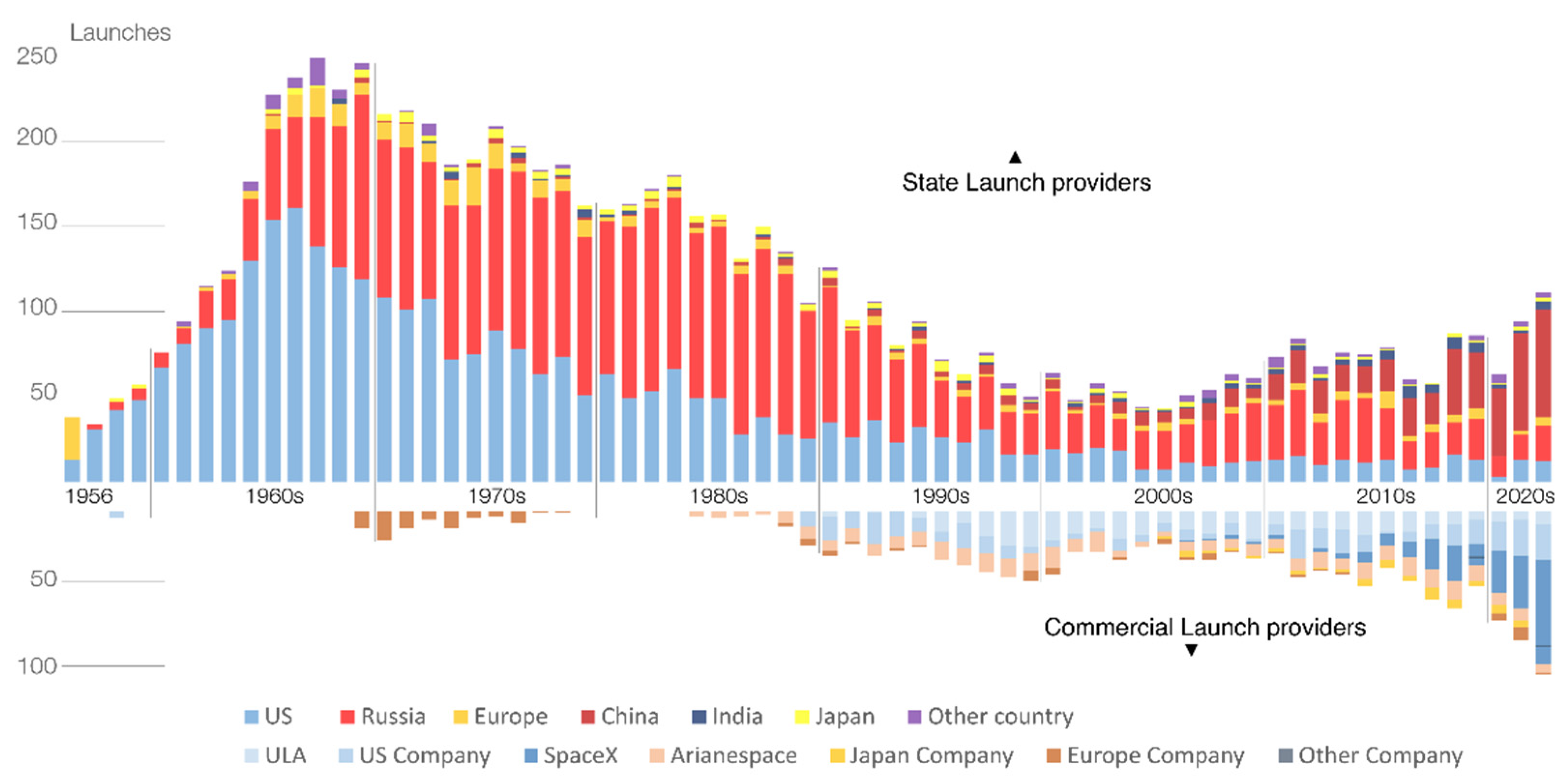
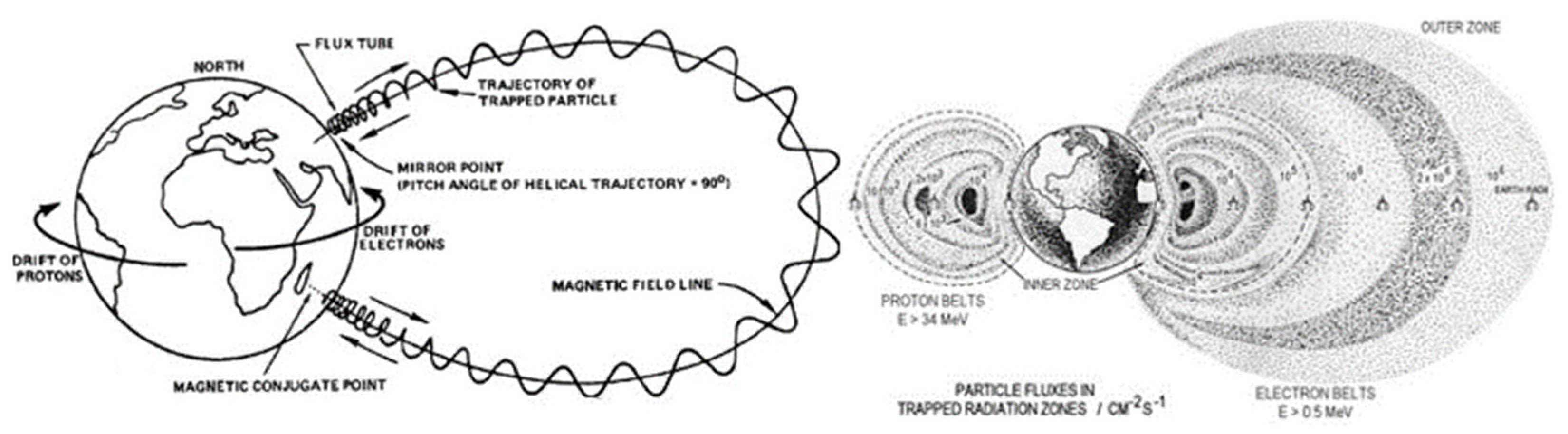
1.1. Space Environment

In the space environment, continuous material degradation, contamination, thermal changes, radiation damage excitation, spacecraft glow, charging, and induced background interference are the most critical hazards that make it a harsh environment. These effects originate from many sources and physical phenomena such as orbital debris, meteoroids, mechanical vibrations, significant thermal variations, protons, electrons, neutrons, high-energy particles, X-rays, and γ-rays. Therefore, in each space mission, devices and systems need to be tailored for these hazards, starting from the material choice to the design and up to the final assembly. This process is carried out considering the mission’s length and the lifetime required. The latest trends in this respect are pushing the performance requirements for aerospace to shift towards lighter exotic materials and more complex spacecraft systems.
Since the late 1970s, optical fiber sensors have attracted attention as one of the most promising technologies for aerospace applications due to their peculiar properties, such as small size, lightweight, immunity to electromagnetic fields, multiplexing capability, and fast response (see Section 4 and Section 5). From the early days of their usage, the effects of harsh environments and, specifically, radiation on optical fibers have been studied. Yet, the large number of glass compositions and configurations made it impossible to completely investigate radiation effects on all the fibers, delaying the acceptance of such potentially disruptive technology for serious reliability concerns.
Similar to all technology that needs to be validated for space and aims to be adopted as a standard, fiber optics also underwent many assessments carried out by several organizations [11]. The standardized protocol must follow these steps:
  • Define the environment of the mission;
  • Evaluate the interaction between environment and space assets;
  • Define the requirements and their criticalities;
  • Assess the design and the performance characteristics of components;
  • Improve the design and performance along with the definition of the design margins and the risks assessments;
  • Iterate the process with updated knowledge.
Since the starting point is the definition of the mission’s environment, we recall the main ones briefly: Low Earth Orbit (LEO), Middle Earth Orbit (MEO), Geosynchronous (GEO), Geosynchronous Transfer Orbit (GTO), interplanetary and other planets.
The different orbits are characterized by their distance from the earth. LEO orbit, the one where the international space station and most earth observation satellites are located, is between 200 and 2000 km from the earth’s surface. MEO orbits are between 2000 and 35,586 km, and they are used by navigation satellites such as the European Galileo system. GEO orbit satellites are at an altitude of 35,786 km, while GTO orbit satellites have a strong elliptical orbit between 42,164 and 35,786 km. These orbits are typically used by telecommunication satellites [12,13,14].
Each of those environments presents a different environment with significant variations; however, all space missions share a common characteristic: long durations. Usually, their lifetime ranges from 7 to 15 years for GEO missions, but it can be even longer [15]. With this primary goal of mission duration, a differentiation is operated in terms of requirements according to the operative environment of the missions, with particular attention paid to the sources of degradation or hazards. As summarized in Table 1, multiple hazards are present in the space environment as a potential source of damage to the structure and fiber optics. Among all the hazards, ionizing radiation and particles are the most critical for OFS. Indeed, three primary sources of particles and radiation interact with optical fibers and are as follows: trapped particles, cosmic rays, and solar energetic particles. Fiber optics degrade mainly through the ionizing process, making solar particles and trapped particles the most dangerous.
Fortunately, trapped particles are only present in a small zone around planets. Indeed, around the earth and any planet with a magnetosphere, there is a toroidal region called trapped radiation belts or Van Hallen radiation belts. Here, charged particles are produced or arrive, and they become trapped, gyrating and traveling along the field lines of the magnetic field. The Earth’s radiation belts range between 200 km and 75,000 km from the surface, and the trapped particles have three components: gyration, bounce, and drift. This causes trapped electrons and protons to have different energies and different spatial distributions, as shown in Figure 2. Electrons reaching up to 7 MeV and protons up to 600 MeV constitute a significant hazard for spacecraft. There are different models for the distribution of the particles and for engineering applications; two static models are mainly used by NASA, AP-8 and AE-8 [18], and improved models (AE-9, AP-9) have been created [17]. Due to a large number of models available, ESA tried to specify the required and recommended method, model, and data for space engineering to make it consistent and improve any space assets’ survivability and performance. All these standards are illustrated in the report ESCC-E-ST-10-04C Rev.1 [19].
Solar particles (or SPE, solar particle event) are also present outside radiation belts, which induce damage by ionizing the optical fibers. They are generated by solar flares and coronal mass ejections, which produce protons, electrons, neutrons, X-rays, γ-rays, and heavy ions. These events potentially lead to high fluxes and fluences of particles with energies variable but inferior to galactic cosmic rays. Even if those energies are inferior to cosmic rays, their fluxes are higher, and SPE has the most impact on fiber-based devices. Galactic cosmic rays (or GCR) are a continuous flow of charged particles that arrives from outside the solar system, and they are primarily atomic nuclei stripped of their electrons [22]. GCRs have more importance for single event effects for higher atomic number elements due to their high energy. This poses a great risk for microelectronics but is of less concern for optical fibers, where the cumulative effect of radiation (called total ionizing dose, TID) has a more significant impact. For these reasons, in the literature, much attention is dedicated to the effect of ionizing radiation on fibers and how to make them resistant to damage resulting in the malfunction of OFSs. This process is called radiation hardening, and in the following, we detail the main issues that OFSs face in the aerospace environment.

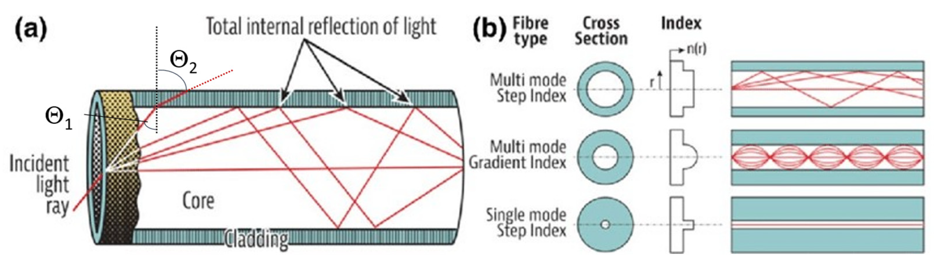
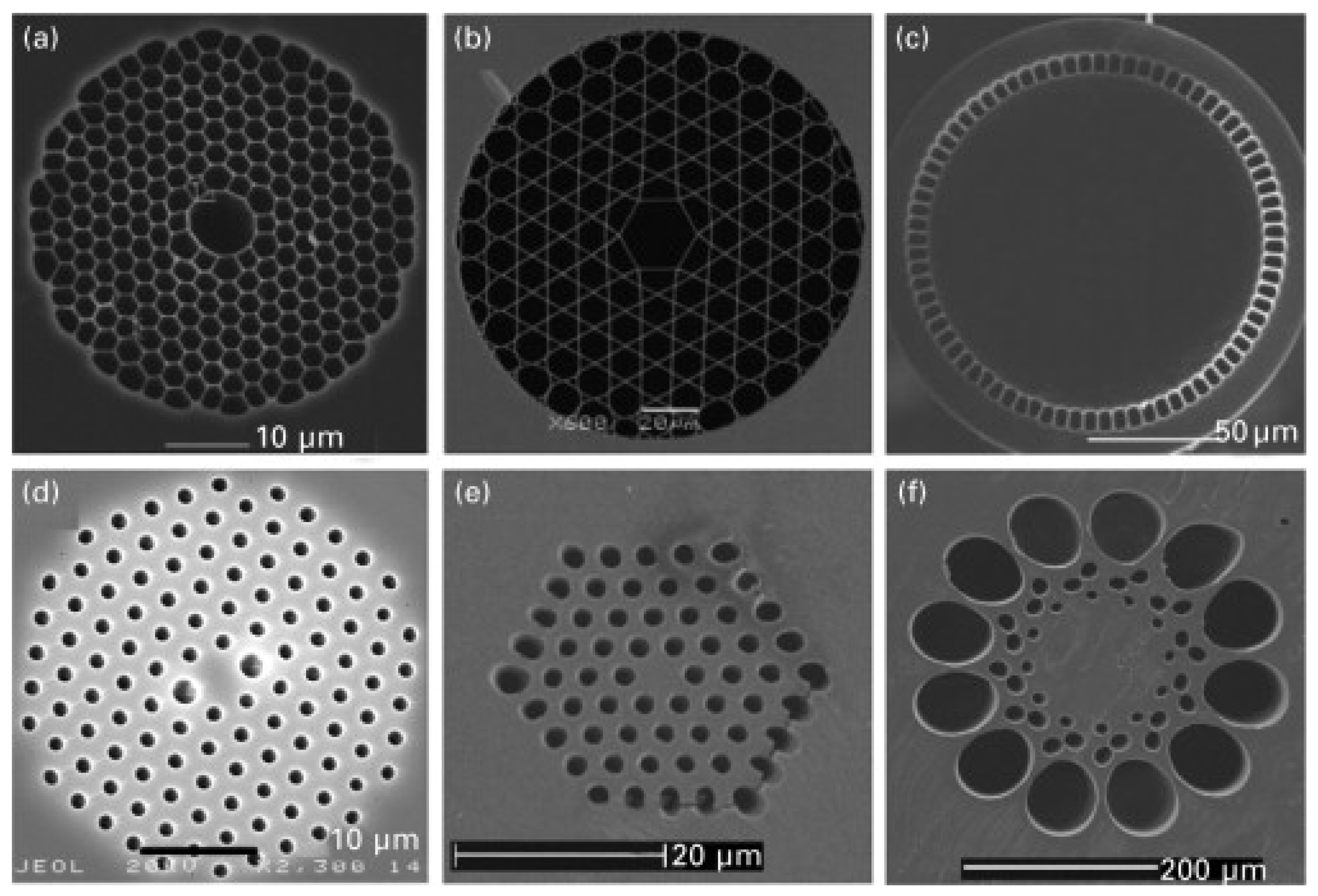
1.2. Types of Optical Fibers

Many different types of optical fibers are available on the market today with many different geometries or materials. Silica-based (SiO2) optical fibers that guide light by a total internal reflection mechanism (TIR) are the most commonly used. This mechanism is shown in Figure 3.
This propagation occurs through multiple reflections at the interface between the core and cladding that is quantified by the so-called Snell’s law:
nCORE sin(θ1) = nCLADDING sin(θfor tens of km with a typical resolution of2),
where:
  • nCORE is the refractive index of the material composing the core;
  • nCLADDING is the refractive index of the material composing the cladding;
  • ϴ1 is the angle of incidence of the light ray at the core-cladding interface;
  • ϴ2 is the angle of refraction of the light ray after reaching the interface.
Snell’s law describes and defines the physical phenomenon that, when a ray of light changes the material within which it propagates, it also changes its direction of propagation from being ϴ1 to ϴ2. To achieve total internal reflection, the condition is that nCORE must be larger than nCLADDING since, in that case, Θ2 is larger than 90°, implying that the refracted ray bounces back inside the core, thus allowing the transmission of information. Under this condition, we can also derive the maximum angle (called critical angle) at which light can enter the fiber and be confined in the core. Light coming at smaller angles is confined in the core and thus guided.
The refractive index (RI) difference between the core and the cladding is obtained by doping the core glass with chemical elements such as germanium or phosphorus, even according to a geometrical profile that defines the allowed guided modes (see Figure 3b). Other materials besides silica can be used as a matrix if other characteristics such as transparency window, the high solubility of rare earth ions, or higher refractive index are desired, such as tellurite, fluoride, and phosphate [24]. According to the materials present in the core, different and complex radiation responses can be obtained by determining the fiber response to radiation.
To provide mechanical and chemical protection to the fiber (core/cladding), the cladding is typically surrounded by a coating, normally made of a polymer such as a polyimide or a polyacrylate. Different protective coatings can be added on top of the polymer coating or in substitution for applications in harsh environments. For example, a metallic layer of aluminum or gold deposited on a silica fiber can increase temperature or radiation resistance [25].
Several classes of optical fibers are obtained by changing the shape and RI profile of the core or the cladding. The primary differentiation in the actual market is between standard and specialty optical fibers [26]. Specialty optical fibers, with different materials or more complex designs, are very interesting for sensors, amplifiers, or fiber-based lasers and have shown future growth potential and growing interest by industries in the last few years. However, their market share is reduced to a few percent compared to the over 50% taken by standard or conventional fiber optics.
Conventional fibers are the most common and can be employed in data transfer, diagnostics, and sensing applications. They are widely used in telecommunications where long lengths are required, and the optical losses need to be as low as possible. Indeed, 0.14 dB/km (1550 nm) losses were achieved recently [27]. Among them, single mode (SM) fibers have a core diameter between 8 and 10 μm, with a cladding diameter of 125 μm. They are commonly made with a step index RI profile (see Figure 3b), where an abrupt difference in refractive index causes the total internal reflection. Doping elements such as Ge, F, Al, etc., can modify the refractive index of the clad and core, and the exact RI is obtained by dosing these dopants in the fabrication process. Most SM applications are meant for long-distance communication and sensors due to their low dispersion and good optical signal integrity. Their response to radiation has been extensively studied over the years in relation to their fabrication process and doping elements. For instance, fluorine-doped fibers showed outstanding resistance to radiation environments by having a radiation-induced loss lower than 5 dB/km [28]. Although such a value can be considered a high loss for an SM fiber in telecommunication applications, the short lengths typically needed for space applications make it a good result. Other researchers found that the fabrication parameters have a significant correlation to the radiation resistance of SM fibers; however, more experiments are needed to provide a sound prediction for the radiation-induced attenuation based on these parameters.
Multimode (MM) fibers have larger diameter cores than SM, more than 50 μm, while the clad might have diameters ranging from 125 μm to 400 μm. They are used for short distances compared to SM fibers in the telecommunication field and can propagate multiple modes. Thanks to the greater numerical aperture compared to SM, it is easier to couple light through them, and cheaper light sources such as LEDs can be connected to such fibers more efficiently [29]. MM fibers are less common for scientific research and only few studies were performed on their radiation behavior [30,31].
Polarization-maintaining fibers (PMFs) are SM fibers in which the guided light maintains its linear polarization state. This is important for some applications such as interferometric sensors, gyroscopes, and coherent communications [32]. There are different ways to obtain polarization maintenance in PMF, as reported in Figure 4. The most common approaches are noncircular core and asymmetrical lateral stress. The latter is used in PANDA fibers in which the asymmetrical lateral stress is introduced by two stress rods made of silica glass modified with boron and placed inside the clad [33]. The presence of stress along one direction breaks the symmetry of the core, introducing a birefringence where the RI has a slightly higher value (slow axis) along one direction. This allows for decoupling the modes in the orthogonal axes and maintaining the polarization if the light is linearly polarized along the direction of one of these two main axes.
PM fibers are especially interesting for aerospace applications since they are a key component of fiber optic gyroscopes (FOGs). Recent improvement in radiation hardening by composition has been made. It has been observed that N-doped fibers under an irradiation of 2–10 kGy (higher than normal space conditions) have losses that do not exceed 5–10 dB/km, an order of magnitude better than standard SM Ge-doped silica core fibers. This makes them an interesting alternative for aerospace applications in harsh environments [35]. The disadvantage of these fibers is their high cost derived from their complex structure and fabrication.
First proposed in the early 1970s by Kaiser et al. [36] to reduce losses, microstructured optical fibers (MOFs), such as the ones in Figure 5, were first only produced in the 2000s due to their complexity of production. There are two main categories of MOFs: structured optical fibers based on TIR effect to guide light and photonic crystal (or bandgap) fibers, which are treated separately as they leverage a different light-guiding mechanism.
Microstructured fibers have an outer cladding with a core made of glass and air with specific geometries. The TIR mechanism is achieved by the difference in refractive index between the core and air. The advantage they have is that they are made of a single material, e.g., pure silica, for the entire fiber [37]. As reported by Girard et al. [38], MOFs showed comparable losses to pure silica fibers in a radiation environment such as the one produced by fusion by inertial confinement (where a microcapsule, filled with deuterium and tritium, is heated and compressed until nuclear fusion ignites). Therefore, they are good candidates to be used as sensors for environments with high doses of radiation. Still, there are many unknown mechanisms in their radiation-induced attenuation (RIA), and additional research needs to be conducted to improve their radiation hardening.
Photonic bandgap fibers (PBGF) are a subcategory of MOFs that use air as a medium to guide the light and a micro-structured web-like cladding of glass (Figure 5a,b). They are based on photonic crystals. A two-dimensional periodic optical nanostructure creates a photonic bandgap, where light propagation is prevented from occurring outside the hollow core and light is kept inside. Being more recent, with a high cost of production and a difficult fabrication process, they are still not widespread even if they show good results under irradiation, especially under steady state γ-rays [40,41].
Rare-earth doped fibers are important in space applications since they are key for IR-fiber lasers, amplifiers, and FOGs. They are active fibers where the doping elements are not used to modify the refractive index but to absorb a pump light of a certain wavelength, typically shorter, allowing the stimulated emission of light in lasers and optical amplifiers. The rare earth doping elements present in the core tend to have strong interactions with radiation, generating complex mechanisms of degradation. Many studies have been carried out on the radiation response of this category of fibers in the last two decades [42,43,44].

2. Optical Fiber Sensor Types

Each optical fiber sensor (OFS) class targets different applications based on the sensing mechanism. The main categories of OFS can be identified as point sensors and distributed sensors. In point sensors, a specific and spatially limited part of the fiber, e.g., a Bragg grating, is sensitive to external stimuli, while in distributed ones, all the fiber can act as a detector. This section compares the main categories and classes of OFS, their sensing mechanism, and their advantages with particular attention applications in the aerospace environment. A detailed description of all the sensing mechanisms is outside this review’s scope but can be found in the references herein.

2.1. Point Sensors

Among the point sensors, the most widely used are fiber Bragg gratings (FBG) and long period gratings (LPG). Even though each type of these OFS has its niche of applications, FBGs are the most studied optical fiber sensors under irradiation and have recently acquired a large market share. The growth forecast of the FBG market in 2028 is expected to reach a global market size of USD 5167.4 million with a 23.9% compound annual growth rate [9].
The main advantages of FBGs are summarized in Figure 6, divided by the different features driving the optimal sensor selection in the various applications. Although some of these advantages also apply to distributed sensors, point sensors generally benefit from a lower cost for the interrogators and a much higher sensitivity. In the following, we review the FBG mechanisms and their relevant fabrication techniques, particularly for degradation mechanisms in the presence of radiation.

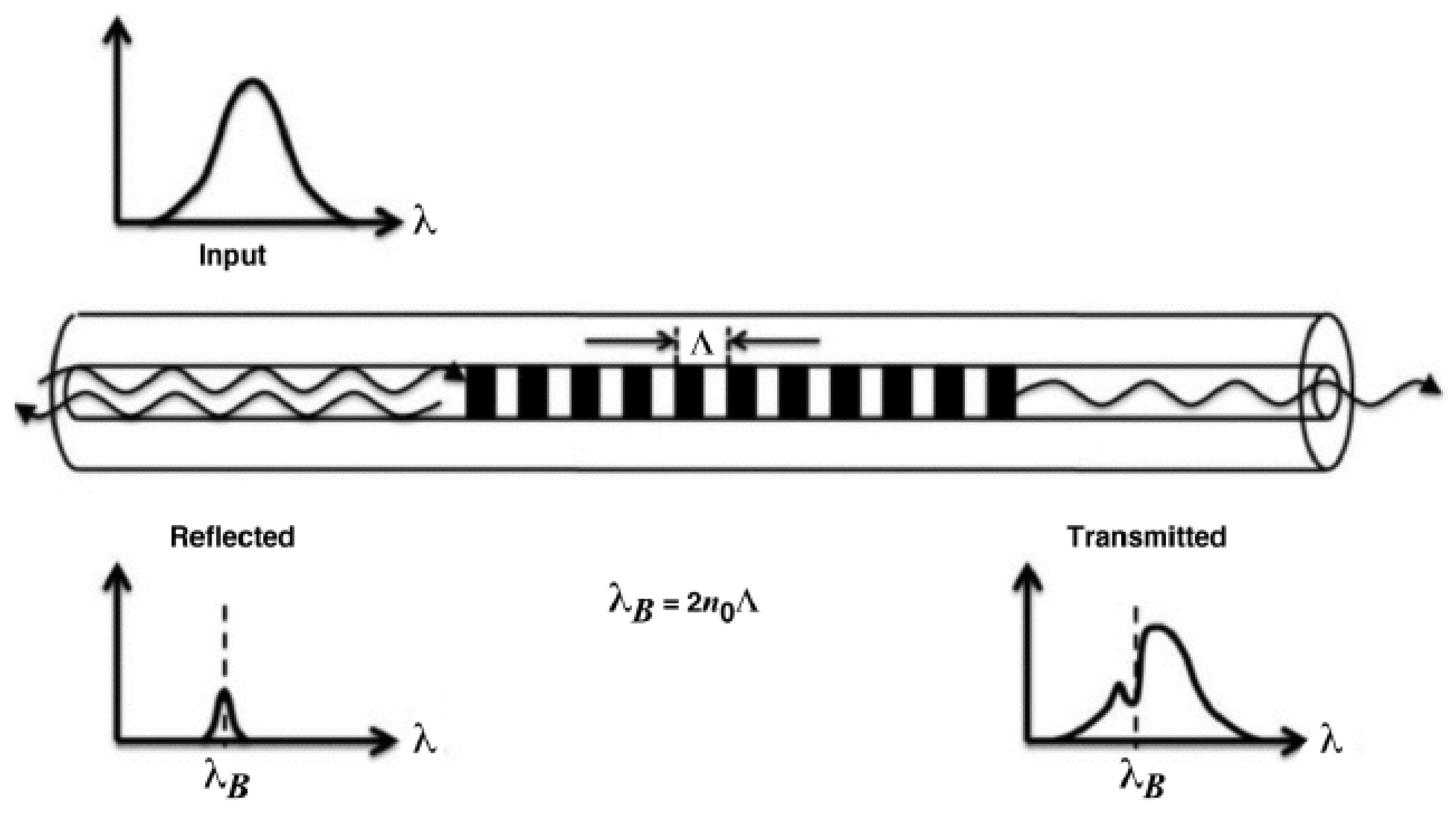
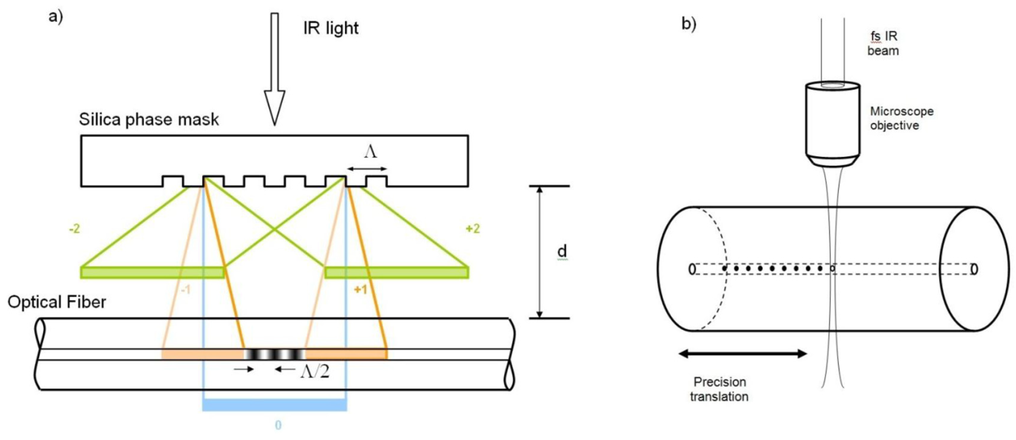
2.1.1. Fiber Bragg Gratings

Fiber Bragg gratings can be seen as reflectors for a very narrowband set of wavelengths (typically 0.2–0.5 nm) and are inscribed directly on the optical fiber’s core. The mechanism of reflection is obtained through a periodic variation (period Λ) of the refractive index of the order Δn = 10−4–10−3, which creates a resonance for a specific Bragg wavelength, producing the peak in reflection related to the periodicity Λ (see Figure 7). The relationship between the Bragg wavelength λB and the periodicity of the index variation in fiber Λ is given by:
λB = 2neffΛ,
where n is the effective refractive index in the core of the fiber. On average, the effective refractive index is in the range n = 1.4–1.5, and Bragg gratings are inscribed (or “written”) on a single mode fiber’s core with a period Λ typically from 0.5 μm to a few μm. This allows for precisely tuning the Bragg wavelength in the spectral region of interest for detection and sensing [47].
Since the Bragg wavelength depends on the refractive index (see Equation (2)), its change causes the shift of the reflection peak. The phenomena that produce a change in the fiber’s RI are temperature variation and mechanical strain. Calibrating the response of FBG with respect to these two parameters allows them to be used as sensors for these two physical quantities. The typical strain sensitivity of commercial FBGs is about 1 pm/ με and for temperature is 10 pm/°C. Still, these values can be increased by using special pre- and post-treatments, fiber coating, and packaging.
Since the periodic variation in the core has a typical extension of a few mm along the fiber, FBGs are considered single point sensors, meaning that only the written part acts as a transducer and responds to environmental changes. Moreover, the wavelength selective response of the FBG related to the periodicity Λ allows for chaining multiple FBGs at different Λ along the same fiber. Such multiplexed interrogation systems can be seen as multipoint sensors or a quasi-distributed OFS if they are tightly spaced [49].
To produce FBGs, different manufacturing techniques have been developed and optimized, and the most common today are [15,47,50,51]:
  • Phase mask (PhM);
  • Point by point (PbP);
  • Free space interferometry;
  • Continuous core scanning.
The first FBG was obtained by Hill et al. [50], who found that the core of standard telecommunication fibers was photosensitive due to the presence of germanium inside the core. Indeed, when exposed to high-intensity visible or UV light, its refractive index would increase proportionally to the light intensity. By modulating the light, it was possible to change the refractive index, creating a periodic pattern.
In the phase mask technique (Figure 8a), a phase mask is interposed between the laser and the fiber, almost in contact with the fiber itself. The mask determines the grating period, producing a diffraction pattern directly related to the spatial modulation of the refractive index to be produced for the FBG. Such a technique is highly reproducible, but each mask can usually produce only gratings working at a specific wavelength, thus requiring multiple masks to cover a reasonable portion of the spectrum where the FBG should operate.
The PbP technique generates each grating element controlling the laser parameters and the fiber movement by focusing the laser light on a single point where the index modification is realized. It is based on the nonlinear absorption of an ultrashort laser pulse (Figure 8b). Such absorption produces damage in the material creating zones inside the fiber where the density is slightly changed. By patterning each point, there is fine control of the periodicity of the FBG, leading to a more flexible pattern generation technique. However, such a technique has a much lower throughput with respect to the phase mask one.
OFSs are commonly used for strain and temperature monitoring efficiently, but they can be functionalized for other applications, as are detailed in Section 4.1.

2.1.2. Grating Types

Type I gratings are also referred to as standard gratings, and they were the first type of FBG to be produced. They have a positive refractive index change created through the reaction between the UV/IR laser and the color centers in the core glass [52]. The first Bragg produced was Type I-UV and used the oxygen deficiency defect centers in a germanosilicate fiber. To increase the photosensitivity, the core needs to be doped with elements such as Ge [53], and if a higher refractive index change is needed, H2 loading can be used. Highly photosensitive Type I hydrogenated fibers are called Type IA.
All Type I FBGs present a temperature-dependent bond-restructuring phenomenon. Indeed, if the FBG is annealed at temperatures below 450 °C, the thermal treatment stabilizes the grating through the thermal depopulation of trapped excited states. However, for temperatures higher than 450 °C, most of the refractive index changes are destroyed by breakage of the formed color centers, especially Type IA.
When a high peak power short-pulsed laser is used to produce the grating over a certain damage threshold of the fiber, Type II FBGs are created. This type of FBG exhibits higher reflectance (<99%) and larger peak width, thus reducing the typical grating length. With UV-lasers, the damage threshold is surpassed, and physical damage is produced between the core and clad, while for IR-lasers, the gratings are realized by the densification of silica. The sensors based on Type II FBGs are more stable and can be used at temperatures over 1000 °C, but they have a lower quality of the reflection spectra, and the fabrication process tends to reduce the overall mechanical strength.
Type I gratings are the former Type IIA, and they are produced with a UV laser on highly stressed Ge-doped fibers. Under certain conditions, a Type I grating starts to grow and then decreases its strength as the gratings saturate. If the exposure continues, a secondary grating starts growing with a negative RI change [54]. Type I gratings are stable up to 700 °C [55].
Regenerated gratings are obtained from the thermal erasure of the grating. The most common way to produce a regenerated grating is using a Type I grating enhanced through hydrogen loading to increase its photosensitivity. The regeneration process is carried out at room temperature, exposing the FBG to high-pressure hydrogen [56]. After UV inscription creates a Type I, the grating is annealed at a temperature between 600 °C and 700 °C, erasing the Type I FBG, but if the heating continues at an even higher temperature, a new grating appears at a longer wavelength. This grating is stable at high temperatures, even above 1000 °C, but its spectral response weakens by order of magnitude, producing a low-reflectivity FBG. The full physical details of the mechanism underlying the regeneration of the FBG are still unknown [57].
A femtosecond pulsed infrared laser can be used to induce large index changes thanks to the high peak power [58]. The mechanism is different from the UV laser gratings since no color centers are involved. However, the absorption/ionization of a nonlinear multiphoton produces local physical damage, leading to increased density or the generation of physical defects. The properties of these gratings are similar to Type II induced by nanosecond UV lasers. This grating has better spectral performance.
The advantage of this FBG is that it can be inscribed on many types of waveguides, not only silica-based UV-sensitive fibers. Therefore other materials can be used, e.g., sapphire, allowing the production of sensors for highly specialized tasks such as high-temperature sensing above 1750 °C on sapphire fibers [52].

2.1.3. Long Period Gratings

Long period gratings are similar to FBG but with a period typically in the range of 100 μm–1 mm, many times larger than the typical wavelength propagating inside the fiber. LPG promotes the coupling of the light coming from the core to the propagating cladding modes [59]. Cladding modes have high attenuation; therefore, the spectrum presents an attenuation band for a specific wavelength related to the periodicity of the LPG. If the environment changes the period or refractive index of the section containing the LPG (typically around 30 mm), these attenuation bands will shift, similar to FBG. LPG sensors have been used for many applications in physical, chemical, and biological sensing [60,61,62,63,64]. The sensitivity for each measurand depends on the composition of the fiber and the order of the cladding mode coupled; therefore, it is possible to have a single sensor that senses multiple parameters.
There are many fabrication techniques for long period gratings to produce the periodic modulation of optical properties by modifying the core’s refractive index or by physical deformation of the fiber. These techniques are shown in Table 2, and the most common is the UV irradiation of germanosilicate fibers.
LPGs attracted the attention of researchers for their use in radiation environments. The first study of their behavior under γ irradiation was by Vasiliev et al. [76] in 1998. A complete review was conducted by Esposito et al. [77], showing the growing interest in these sensors while, at the same time, underlining the need for further studies on the influence of dose rate and irradiation temperature on their performance.

2.2. Distributed Optical Fiber Sensors

Distributed optical fiber sensors (DOFS) are meant as an improvement in spatial resolution attainable with quasi-distributed system (or multiplexed system) point sensors such as FBGs. The first DOFS system was based on the optical time domain reflectometer and allowed the spatial measurement of any environmental parameter that influenced the fiber’s attenuation with a spatial resolution ranging from 0.1 m to 10 m [78]. DOFS are based on a scattering phenomenon that occurs to light during the propagation inside the fiber optics. Currently, based on the used mechanism, three main technologies are available in DOFS: Rayleigh, Brillouin, and Raman. Other technologies exist, such as the optical carrier-based microwave interferometer, but they are infrequent in most of applications [79].
Scattering is a random statistical phenomenon that occurs in all angular directions, and in the case of elastic scattering, the frequency of the scattered light is conserved with respect to the input one (Rayleigh). Additionally, if the frequency of light or its energy changes during the scattering process by absorbing or giving energy to the fiber material, then the scattering is called inelastic (Raman and Brillouin). DOFS can thus be classified by what happens to the frequency of the incident light and the occurring scattering mechanism, as shown in Figure 9.
In Rayleigh-based DOFS, a propagating pulse of light in the fiber can maintain its central wavelength, while perturbations along the propagation broaden its optical spectrum. Such elastic scattering originates from material density fluctuations, dopant concentration, or fiber perturbation (strain or temperature) reaching the fiber’s core. Due to its isotropic nature, not all the Rayleigh scattered light goes in the same direction: part follows the initial propagation direction, and part is backscattered (against the propagation direction). These sensors use the backscattered light as in optical time-domain reflectometry (OTDR). When an external perturbation changes the density or dopant concentration locally, its intensity can be measured by the difference signature of the backscattered light before and after [79].
There are two approaches that use this phenomenon:
  • Optical time-domain reflectometry is the simplest and measures the intensity of the backscattered light. Each measurand is dependent on the intensity, and the time of arrival of the sensed light is correlated to the distance propagated along the fiber.
  • Optical frequency-domain reflectometry (OFDR) is more complex and is based on the analysis of the measurement of light over two polarization states obtained by the reference light. The position where the variation is happening is related via a complex elaboration of the optical frequency signal.
The advantage of OFDR is that it has greater spatial resolution along the fiber than OTDR, which is at the meter level. In addition, OFDR also has a large dynamic range at the expense of a more complicate and expensive interrogation system [80].
To overcome some of the shortcomings of these two techniques, a couple of less-used and still-developing approaches were used. Incoherent optical frequency-domain reflectometry is used to detect with a high spatial resolution over a long range. Indeed, a spatial resolution of 11.2 cm over 151 km was demonstrated [81]. Optical low-coherence reflectometry (OLCR) has been developed for the high spatial resolution measurement of small optical components with fine structures thanks to a higher than −95 dB reflection sensitivity [82]. It has micrometer-level resolution but a measurement range of less than a few meters.
Brillouin-based DOFS uses inelastic scattering given by energy transfer between photons and acoustic phonons. This interaction leads to a frequency shift of a quantity named Brillouin frequency that is proportional to the effective refractive index, the medium’s acoustic speed, and the incident light’s wavelength. The effective refractive index is the speed of light in a waveguide, such as an optical fiber, divided by the speed of light. This is the propagation speed of waveguide modes. Brillouin frequency varies between 9 and 13 GHz. The acoustic speed is related to the density of the medium; therefore, the change of density by temperature or strain is translated into a change of the Brillouin frequency. These sensors can be used to detect strain and temperature at the same time for tens of km with a typical resolution of 1–10 m.
Brillouin optical time-domain reflectometry (BOTDR) was first developed by Kurashima et al. [83] in 1993. This technique is single-ended and similar to Rayleigh’s OTDR but has few variations. Normally, direct detection is used as in Rayleigh DFOS, but there is also heterodyne detection, which employs a reference signal and allows for a longer sensing range and better performance, improving receiver sensitivity [84]. In the last years, there have been great improvements in BOTDR achieving great sensitivity for temperature and strain measurement. The maximum range achieved was 100 km, while the spatial resolution went down to 20 cm, and a minimum temperature shift of 0.37 °C and a deformation of 7.4 με were reported [79].
Another technique employed in DOFS is the Brillouin optical time-domain analysis (BOTDA), which is based on stimulated Brillouin scattering (SBS). In this configuration, the sensing pulse of light is injected on one end of the fiber, and at the other end, a counter-propagating CW laser is injected [85]. The detection technique is similar to standard OTDR systems, and in the same way, BOTDA achieved great improvements in the last years by reaching a longer sensing range of 150 km and a spatial resolution of 10 cm. Such improvements on the range and spatial resolution come at the expenses of the sensor sensitivity. Indeed, the maximum temperature sensitivity obtainable is 1.5 °C and the strain sensitivity of 20 με [79]. BOTDA obtained inferior ranges (up to 10 km) but a high spatial resolution of 2 cm, reaching a strain sensitivity of 70 με.
Another technique developed is Brillouin dynamic grating (BDG), which involves dynamically reconfigurable gratings. The BDG paired with PM fibers achieved sensitivities for temperature and a strain of 0.08 °C and 3 με, respectively [86]. By lowering the sensitivity, a spatial resolution of 20 cm was obtained [87].
Raman-based DOFS exploits an inelastic scattering phenomenon due to the interaction with optical phonons. As for Brillouin, the Raman shift is the difference in frequency between the pump photons and the scattered ones. Raman DOFSs are only sensitive to temperature and not strain and have been recently widely adopted for environmental monitoring [88]. Raman scattering has a small cross-section and thus tends to produce weak signals. Therefore, higher laser power must be used while avoiding stimulated Raman scattering. The most-used technique is Raman OTDR, and the highest spatial resolution achieved was of 1.2 cm with a sensing range of 2.8 m [89]. Commercially available Raman OTDR has a typical spatial resolution of about 1 m.
Raman OFDR is very similar to OTDR systems and can achieve 2 °C of temperature sensitivity, with a spatial resolution of 1 m on 16 km. The highest temperature accuracy reached was with an OTDR coupled with image processing that achieved 0.004 °C with a spatial resolution of 2 m [90].

2.3. Comparison of Point and Distributed Sensors

Point sensors with FBG gratings present an easy-to-use setup, a low cost, a small form factor, and a wide measurement range, but they are fragile by themselves, and typically, a package is required as protection. Typical FBG sensors have 1.21 pm/με which is relatively low, and in the last years, new advancements were made to increase it up to 31.4 pm/με, as Nawrot et al. [91] demonstrated in 2017. Zhang et al. [92] developed a Bragg strain sensor with a range of −1500–400 με for high-temperature applications. It is possible to multiplex a point sensor system to achieve quasi-distributed monitoring, but this increases the cost sensibly if large lengths are required to be monitored. The temperature application range for most of FBGs is <450 °C, but new femtosecond FBGs reached stability till 1000 °C, the highest among the OFS. The spatial resolution can be higher than other sensors with less than 1 mm resolution [93]. LPG sensors show higher mechanical strength compared to Bragg gratings but generally at a higher cost.
DOFS has the advantage of being already completely distributed, showing high sensitivity and fair precision. Each DOFS’s technology has a different resolution topping for Raman sensor at a resolution of 0.004 °C for temperature and 2 m of spatial resolution. Generally, distributed sensors have a spatial resolution of 1–10 m, with some reaching 100 m. The maximum temperature at which they are stable is normally much lower than for FBGs, and for regular fiber optics, it goes up to 600 °C. Only coherent Rayleigh can reach a spatial resolution in the order of mm.
It is important to remark that, for all of these sensors, in harsh environment applications, it is absolutely necessary to combine at least two technologies to sense strain and temperature simultaneously along two different fibers.
FBG sensors have been considered to substitute older electronic-based sensors in aerospace applications, but DOFS have found much more limited use in such applications. From a radiation response point of view, Bragg sensors have a great advantage: only the grating is the sensitive part, and the interrogation system, affected by radiation, can be installed far away. On the contrary, distributed fibers have much more delicate, sensitive, and expensive electronics, which is significantly more exposed in a radiation environment. In addition, for certain types of fibers (phosphosilicate), DOFS is strongly affected in the measurement along the fiber in the presence of radiation.
Overall, the main advantage of DOFS is the possibility of having a very long sensing fiber (up to tens of km), although for monitoring only a few critical points (up to hundreds), quasi-distributed systems are much simpler, cheaper, and more reliable.

3. Fibers and Optical Fiber Sensors in a Radiation Environment

The advantages of the use of optical fibers for data transmission and sensing applications have sparked interest in their usage in a radiation environment. This fact has driven the studies of fiber optic radiation sensitivity in nuclear and space applications. Both applications are considered harsh environments, although they present different profiles in terms of radiation dose rates, atmosphere, and temperature conditions. The assessment of radiation damage of silica glass in harsh environments was initially made in the mid-1950s for amorphous silica in a nuclear reactor by Primak, Fuch, and Day [94]. However, only about forty years have passed since an extensive study on optical fiber behavior under irradiation was carried out [95,96,97]. In the context of fiber sensors for radiation environment applications, the radiation profiles present a multifaceted scenario. Figure 10 shows the typical radiation doses for different environments. In particular, we underline that space missions have low dose rates and modest total dose rates of radiation compared to fusion reactors. This fact places aerospace applications on a middle ground with respect to the requirements in terms of radiation tolerance between standard ground applications and extreme nuclear environments.
Besides dose rates, different types of ionizing radiation must be considered when comparing space and nuclear environments. Protons, electrons, and heavy ions mainly compose space radiation, while the environment of nuclear applications has high doses of gamma and neutron radiation [99]. At the macroscopic scale, the main radiation effects that can impair the functionality of optical fibers and thus the related applications are radiation-induced attenuation (RIA), radiation-induced emission (RIE), and radiation-induced refractive index change (RIRIC).
RIA appears during irradiation and consists of the fiber’s linear absorption increase due to the formation of new defects at the molecular level. This results in an increase in linear attenuation growing with the cumulative dose. Therefore, this process is time-dependent and wavelength-dependent and usually partially recovers after the radiation stops. An example of a typical evolution of this effect for different wavelengths and radiation times is shown in Figure 11 for different exposure times.
The RIA is normally calculated through this formula:
α RIA   ( dB km ) = 10 L   km     log   I I 0 ,
with I and I0 being, respectively, the intensity at a given time and before the pulsed exposure to radiation. RIA is commonly the main factor to consider in protecting fiber optics in a radiative environment because it can dramatically degrade the propagation distance. Indeed, an increase of losses from 0.2 dB km−1 to 2000 dB km−1 at 1550 nm has been reported for SMF28 fibers after only a few tens of nanoseconds of radiation [101]. It is interesting, anyway, to point out that, apart from being one of the significant limitations to the use of optical fibers in a harsh environment, RIA can also be used to obtain optical sensors for radiation sensing or dosimetry, as demonstrated by the DESY facility [102].
Radiation-induced emission occurs when a sample under irradiation emits parasitic light that superposes on the propagated signal, as illustrated in Figure 12. RIE can originate from different mechanisms. Cerenkov light is observed only during the irradiation run for a high flux of sufficiently energetic particles. In addition to Cerenkov, luminescence signals from pre-existing defects and radiation-induced defects can be observed during irradiation too. RIE has an impact on fiber optic sensors since it affects the signal-to-noise ratio (SNR), increasing the noise levels, especially in the visible window and in an environment with a high dose rate (such as MegaJoule class lasers). As well as the RIA, the luminescence of RIE has been exploited to monitor the dose rate or the particle flux in different applications [101,103].
Two mechanisms cause radiation-induced refractive index change (RIRIC), density change of the glass matrix of the fiber according to the Lorentz–Lorenz [104] formula and the RIA described by the Kramers–Kronig relations, which define the relation between the refractive index and the absorption [105].
The compaction or swelling of the glass leading to a change of the refractive index was first observed in bulk silica irradiated by fast neutrons by Primak [106]. The density change depends on the irradiated material’s phase. For instance, both amorphous and crystal silica phases change into the metamict phase [107] when irradiated by neutrons. Although amorphous silica has a 3% increase in density and RI, α-quartz decreases by more than 10%. The relationship between density changes and the refractive index caused by neutron irradiation in silica is shown in Figure 13.
RIRIC may also affects the optical waveguide structure leading to the appearance of new loss mechanisms [108]. At a microscopic level, it is well known that, when the radiation interacts with the glass matrix of the fiber, there are mainly two phenomena that create defects: knock-on damages, with the displacement of atoms, or ionization processes, depending on the energy of the incoming particle. For silica fibers, the matrix is mainly composed of Si and O atoms that need 18 eV and 10 eV to be knocked out of their original positions, respectively [109]. In ionization processes, instead, an electron–hole pair is formed by the electron jump from the valence band to the conduction band, leaving a hole behind. The formed pair can recombine radiatively, where at least a part of the energy is released as light emission or luminescence, or non-radiatively, in the form of phonons or secondary radiolytic processes that can generate point defects turning into new optical losses [110]. The radiation-induced color centers (or point defects) largely depend on the composition of the analyzed glass; therefore, reviews on this argument are continuously updated to summarize the evolution of the knowledge on this matter, and some examples can be found among these references [103,110,111,112,113].
The matrix of the fiber’s glass can already have defects such as dangling bonds or impurities, called precursor sites, and they disappear while the radiation-induced point defects increase through the same phenomenon, the trapping of radiolytic electrons and holes. Although every year there is an advancement in the knowledge of the kinetics of some defects, only a few defect types are fully known and currently can be studied.
Nonetheless, a good amount of data for pure silica and G-doped or P-doped silica defects have been collected. Most of the precursor sites and radiation induced point defects absorb in the ultraviolet-visible band; therefore, the RIA will be higher for the UV and visible regions of the spectrum and lower for the near-IR. Unfortunately, the contribution of these defects depends also on their localization in the cross section, and their generation or bleaching are also affected by the internal stress of photobleaching. Confocal microscopy of luminescence (CML) and cathodoluminescence (CL) have been employed to study these mechanisms, showing promising results [114,115,116,117].
The RIA in IR is still under investigation because UV-visible absorption band tails do not account for all the optical losses. No absorption bands for silica fiber or Ge-Doped fiber are present in the IR; therefore, the defects causing this loss mechanism still need to be identified. For SM fibers in the IR domain, it is also important to evaluate the effect due to fiber-guiding properties on the RIA spectral dependence [103]. However, if the total dose continues to increase, the RIA will decrease instead due to the increased bleaching rate of its defects that outgrows their generation [103,118,119].
Most space missions in harsh environments have a long lifespan; therefore, experiments on RIA are made at accelerated dose rates to test for the target doses over the mission lifetimes. Griscom et al. [120] demonstrated that the dose rate could change the RIA for most fibers. Moreover, a faster dose rate increases the point defect generation but not the bleaching, resulting in a greater RIA.
The defect’s stability is affected by the temperature; therefore, the RIA changes considerably even with just a few degrees of temperature variation [121]. Figure 14 shows the RIA of different fibers at room temperature (RT) and at liquid nitrogen temperature (LNT).
Most of the studies are made between −50 °C and 100 °C, roughly corresponding to the temperature ranges of the dosimetry and high-energy physics applications. However, space application needs a broader temperature range between −200 °C and 260 °C [123], and nuclear application needs even higher temperatures reaching 800 °C [124]. Only a few works have investigated such high temperatures while showing this study’s importance in understanding fiber behavior in different radiation environments. For example, RIA is divided by a factor of 100 at 400 °C for high-purity UV grade silica fibers [125,126] compared to room temperature, while in the cryogenic regime, the RIA was found to increase at temperatures as low as 77 K [127]. Temperature influence was also studied for pure-silica bulk glass irradiated by very fast neutrons [128,129] and for a variety of point defects: silica point defects [110], phosphorus defects [130], and germanium defects [131]. For aerospace conditions, only temperature response [132] or radiation response were independently investigated, and a comprehensive study comprising both variables still needs to be addressed.
Another phenomenon that can change the fiber behavior under irradiation is the power level of injected signal that, for high values, can cause photobleaching as reported by Henschel et al. [133]. Their work demonstrates how photobleaching is less important in more recently produced fibers and nearly negligible for Ge-doped telecommunication fibers.
Different experiments have been carried out on commercial SM and MM fibers in the near-IR [134]. Radiation tests were also conducted on prototype MM in the visible [135,136,137,138], while fluorine-doped fibers were tested at 1542 nm [139]. In the near-IR, aluminosilicate fibers were used as dosimeters [140] and were proposed as radiation-tolerant fibers. Studies on single mode emitters, fibers, and photodiodes with gamma radiations up to the MGy level were conducted by Berghmans et al. [141], obtaining low RIA even at 3 MGy of total dose with a dose rate around 3 kGy/h. For higher dose rates, such as 25 kGy/h, and higher temperatures, this is no longer true, with losses from 15 dB to 20 dB over 100 m long fibers. From a practical standpoint, standard optical connectors showed degradation, but fusion splices demonstrated far better resistance with an insertion loss of around 0.5 dB with 20 MGy of total irradiation, constituting acceptable losses for a small number of splices.
To illustrate the radiation-induced loss of a commercial-off-the-shelf (COTS) 100 μm core fiber, we report in Figure 15 its RIA over time for different dose rates (0.3–2 kGy/h) for a total dose of 1 MGy.
Other measurements were made on COTS optical fiber, vertical cavity surface emitting laser diodes, LEDs, multimode photodiodes, and WDM components [142]. The optical losses originating from radiation from the different optoelectronic components, including fibers, can be considered in the system power budget and its performance over time.
Focusing the attention on optical fiber sensors, we must first underline one of the key advantages of using these sensors in harsh environments: the possibility of having only the sensing part (i.e., the fiber) exposed to radiation while the interrogation unit could be located far away in a more protected environment. This facilitates the study of the radiation tolerance of a sensor system, limiting the investigation to the optical fiber and avoiding studies on all the electronics. Concerning FBG sensors, radiation influences their responses in two ways. RIA degrades the grating performance by decreasing the SNR, lowering the peak until it appears undetectable [76]. In addition, RIRIC affects the Bragg peak, causing a decrease of peak reflectivity and a wavelength shift as illustrated in Figure 16 [144]. The main parameters influencing the radiation response of FBGs are fiber parameters, irradiation conditions, FBG types, and writing conditions [15].
Under irradiation, distributed sensors suffer from a substantial reduction of the available sensing length caused by RIA. The entity of such reduction depends on the harsh environment, the fiber type, and its profile of use. In Figure 17, we report the decrease of sensing length for different kinds of optical fibers under irradiation for different doses.
In addition to this effect, it has been observed that radiation can change the structure of the silica glass, especially in case of high fluences of neutrons, inducing an error in the evaluation of sensor measurand (temperature, applied strain, etc.). For distributed sensors, Rizzolo et al. [145] demonstrated the success of in situ temperature measurements with a Germane-silicate commercial SMF28 fiber up to 1 MGy total dose of 10 keV X-rays, which did not alter the physical phenomenon of scattering. Studies on optical frequency domain reflectometry with a total dose of 10 MGy showed that the scattering properties are not affected, and their sensing mechanism works as in pristine conditions (without radiations). The RIA for radiation-resistant fibers (F-doped and pure silica core fibers) stays under 55 dB/km, which is acceptable for most of the applications of these classes of sensors. However, the overall sensing lengths for DOFS are generally significantly reduced for radiation environments. This could explain the preferred adoption of FBG/LPG sensors in this type of application.

4. Radiation Hardening of Optical Fibers for Aerospace Applications

To prolong the operational life of optical fibers and optical fiber sensors in a radiative environment, the strategy of choice is to “harden” them against radiations. For that, the two most commonly used approaches are hardening by component, where there is an improvement on the material by employing a new class of glass, and hardening by pretreatment, where the fiber core is loaded with a reactive gas that stabilizes against radiation. In this section, we give an overview of these two hardening strategies for completeness, while, for a more detailed treatment, the reader is encouraged to consult the reported bibliography.

4.1. Radiation Hardening by Component

To achieve the radiation hardening of fibers, a custom tuning of the composition must be implemented, in particular, fixing the target operational spectral domain and the environmental conditions. In fact, no optimal composition exists that allows the design of an optical fiber with a reduced radiation sensitivity for all harsh environments at all wavelengths. For instance, fiber’s composition with low RIA for infrared applications under γ-rays can have a poor response in other environments.
In this context, most of the research has been carried out for radiation environments up to a few MGy and for operating spectra from the visible to the IR. As examples, we here recall that fibers for plasma diagnostics in the ITER facility and fibers for the data links at the Large Hadron Collider have been thoroughly studied, driving the choice for these applications towards pure silica core (PSC) and fluorine-doped fibers [146,147,148]. To improve the RIA of PSC, the first step is to reduce impurities. Dry silica has a low impurity level but a higher amount of chlorine, which lowers the transmission in the UV. In comparison, wet silica has a higher amount of hydroxyl and a low chlorine content, which is better for ITER requirements. With chlorine and hydroxyl defects missing, the fiber obtained is worse due to the creation of new defects that are unstable even at room temperature, known as self-trapped holes (STH) that produce absorption bands in the visible range.
For space applications, it is important to study doped core fibers used for several applications, e.g., Er-Yb doped fibers for amplifiers in space applications that use the co-doping with cerium [149] and Ge [150] to decrease the RIA by a factor of almost 25%.

4.2. Radiation Hardening by Pre-Treatment

A very efficient approach to the radiation hardening of fibers is the pre-treatment of the fiber core with a gas that reacts with the radiation-induced point defects and passivates them, producing more stable bonds that do not significantly affect the optical properties. For the PSC and F-doped fiber used in nuclear applications, the presence of hydrogen was reported to increase the performances in the visible spectrum by the passivation of the non-bridging oxygen hole center [148,151,152].
Similar to the hardening by component approach, drawbacks are also present in the gas passivation process. Indeed, hydrogen reacts with the oxygen of the Si-O matrix to create hydroxyl groups, whose presence increases the IR’s absorption and can combine to create new defects absorbing in the UV. The use of deuterium was also explored, giving some small benefits over H2 for signal propagation in some applications [153]. The main problem with hydrogen and deuterium is that, at room temperature, the gas diffuses out of the fiber in a few tens of hours, which makes it unable to be used for long missions in space environments. Oxygen has also been proposed as a solution because of its lower mobility. Indeed, oxygen can be added at high temperatures and pressure or as an excess dopant during the fabrication of the fiber, giving better RIA performances in the IR while negatively affecting the UV region [154,155,156].
Another pre-treatment used is pre-irradiation, which transforms in optically active point defects the precursor sites and then bleaches the defects. In this case, the approach exploits the fact that having fewer precursor sites gives a better response to irradiation, as demonstrated by Griscom [157,158].

4.3. Other Strategies for Radiation Hardening of Fiber

Operating conditions greatly impact the radiation response of the fiber and might be easier to adjust than changing the fiber composition or using a radiation pre-treatment. In particular, the main parameter to be tuned is the operating optical signal region. Higher wavelengths in the IR spectrum are more desirable since fewer point defects produce absorption in that region [159]. When irradiated by steady-state γ-rays, the best performing wavelength for sensing is around 1–1.2 μm [160]. Aside from hardening the optical fibers, a classical shielding approach can also be used. Aluminum is a commonly used shielding material, and in Figure 18, we report the effective dose of different particles with respect to various amounts of aluminum in the shielding layer. Figure 19 reports the total ionizing dose calculated for a solid sphere of aluminum for space missions with different duration.
Although aluminum is a commonly used material for shielding in space environment due to its characteristics, e.g., lightweight, and well-integrated with space constraints, its shielding performance is poor compared to other materials, as shown in Figure 20. Indeed, other materials such as some polymers (PPS, Kapton, PEEK) and even water can have much better shielding properties [162].
Shielding is a common solution for radiation protection for electronic devices or the astronaut’s safety, but it directly translates into adding materials that eventually increase the overall weight. For this reason, improving the radiation resistance of optical fiber sensors is still crucial, and a joint approach combining fiber composition and shielding could be an enabler toward the widespread use of fiber sensors in the aerospace industry.

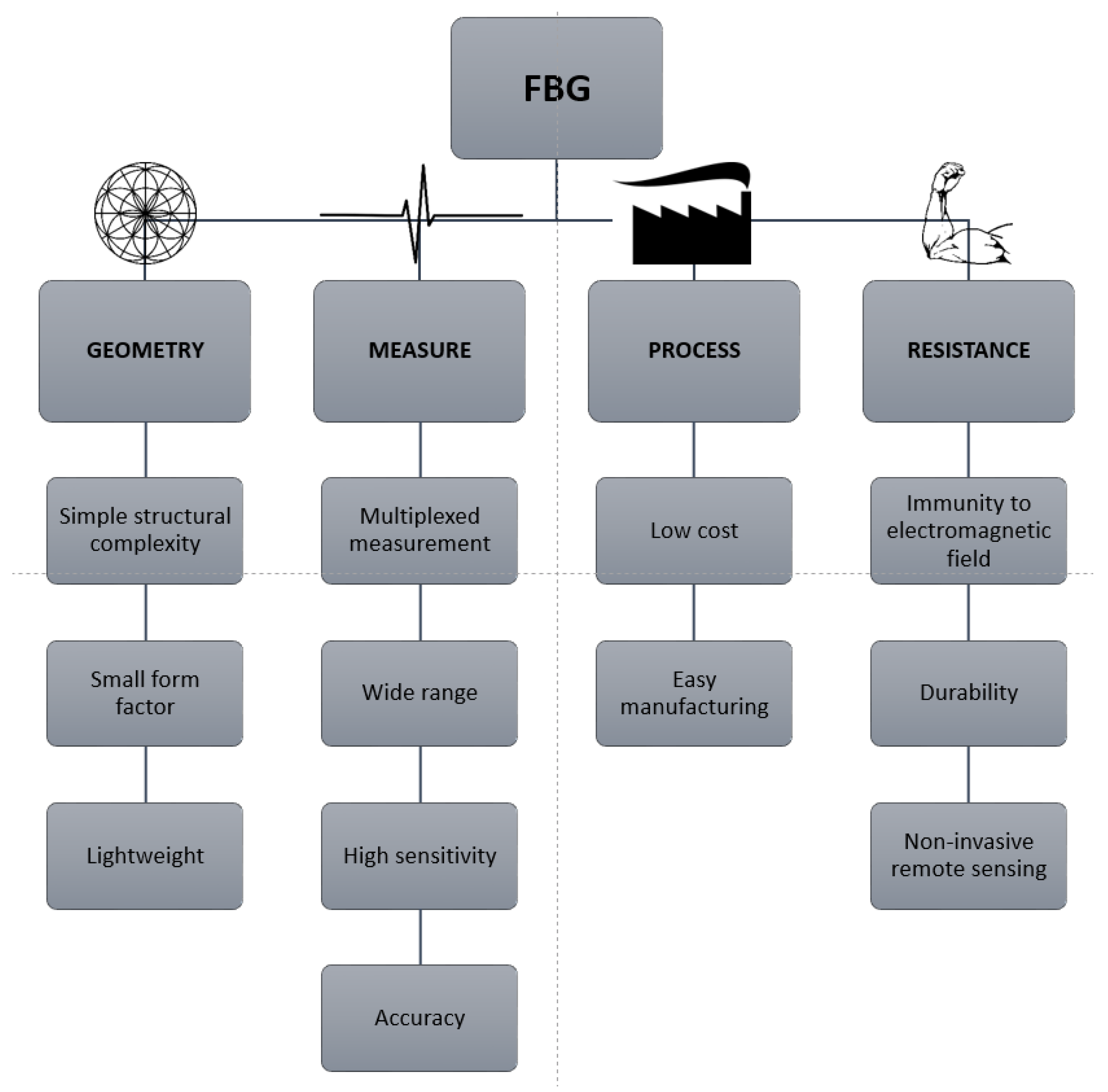
5. Advantages of Fiber-Based Sensors

Optical fibers are suited for many aerospace applications thanks to their high bandwidth, multiplexing capability, and low attenuation level [46]. Thanks to their electromagnetic interference immunity, many aircrafts, such as the Eurofighter “Typhoon” and the Boeing 777, started to include optical fibers for on-board data communications since the 1990s. In the last twenty years, optical fibers have been considered not only for communication networks but also as sensors for different applications, particularly for the structural health monitoring of aircraft. Indeed, one of the most stringent constraints in aerospace applications is weight, and the lightweight optical fibers perfectly suit the requirement for lightweight devices [164,165].
The trend of the adoption of lighter construction materials such as fiber composites in aircraft manufacturing and the possibility of implementing prognostic functionalities on components implies that structural health monitoring is vital to improve safety and reliability while minimizing maintenance costs and manpower. Thanks to their small footprint, optical fiber sensors can be easily embedded in different materials, e.g., graphite/epoxy composites, as demonstrated for spaceships [166,167]. Electrical devices in space have two reliability problems: sensitivity to electromagnetic interferences and connectors. Optical fibers address thanks to both their natural immunity to the electro-magnetic environment and the possibility of making “daisy-chained” systems of multiple sensors along a single fiber with only one connector. As a comparison, we recall that single-axis electrical strain gauges have three connectors, decreasing reliability and occupying more space. Optical fibers are also resistant to high temperatures, and the coating, usually a polymer, can be designed to withstand the typical temperatures of aerospace vehicles. A polymer category that is of interest for aerospace applications is polyimide, which has high mechanical resistance and can resist up to 300 °C. If higher temperature resistance is needed, a gold coating can be used on the fiber to achieve operational temperatures of 800 °C. While the electrical resistive strain gages are limited in sensitivity due to electrical noise, OFS do not have this constraint and do not require continuous interrogation [168], thus requiring low power per sensor. As an extreme example, we recall that Zhu and Chen investigated how heat treatment and polymer coatings can influence and improve stability up to 1000 °C [169]. Moreover, Rayleigh scattering-based DOFSs have been demonstrated to sense strain and temperature simultaneously, inside furnaces, with greater accuracy than thermocouples [170].
Concerning the resistance of fiber optics in the space environment, there are already many different applications. As an example, we recall here that, in 1992, the Small Explorers Program (SMEX) proved optical fibers as a viable option for telecommunication by being at the heart of the optical fiber communication system that was still functional after 16 years [171].
Besides communication and sensing, other fiber optic-based applications were implemented in space, such as the Light Detection And Ranging (LIDAR) system used on the Bepi Colombo and SWARM mission and the Raman laser spectrometer for the ExoMars rover in 2020. Many applications of OFS can be found in the aerospace sector, and the most significant examples are reported below.

5.1. Structural Health Monitoring

Structural Health Monitoring (SHM) aims at continuously monitoring structures for damage, improving reliability, safety, and maintenance costs while reducing human intervention. Indeed, not only is this useful for fault detection but also for predictive maintenance. Different studies revealed the positive impact of SHM [172,173] through fiber Bragg gratings point sensors or interferometers distributed sensors. Health diagnostic is especially interesting to implement in the design of new reusable launch vehicles and for the new composite materials employed in the aerospace industry where it is important to monitor stress factors. For example, the Thermal Protection System (TPS) is resistant to high temperatures and has high strength but has a brittle fracture mechanism, and a single fracture can lead to a catastrophic outcome, as in the Columbia shuttle tragedy.
Real-time sensing of multiple characteristics, such as mechanical stresses, temperature, and vibrations, is an upgrade compared to traditional nondestructive evaluation inspections. Besides the higher monitoring accuracy and immediate response to critical situations, it decreases the wearing of the structure caused by repeated disassemble and reassemble cycles.
SHM is a process that consist of multiple steps. First, periodic readings of the structure are taken with sensors using sampled dynamic response measurements. Then, damage-sensitive features are extracted to make a statistical analysis to determine the current state of health. Finally, a periodic update of aging and degradation effects on the structure is realized [174,175]. SHM is a key technology also for intelligent unmanned vehicles [176,177]. Different applications are currently being studied, such as strain sensing of solar sails. Coupled with actuators, they can monitor the deformations of the tripod typical of a telescope structure and counteract deformations. The analysis of deformations caused by strain and temperature of EXPERT atmospheric entry vehicle is also undergoing [178]. In Figure 21, we report two examples of OFS applications in structural health monitoring systems, showing their placement in critical parts of the aerospace structure.
Another successful example is the European FP7 PEASSS (Piezoelectric Assisted Smart Satellite Structure) project that created a 3U CubeSat with an FBG interrogator and 6 FBG sensors for strain and temperature sensing. It was demonstrated to work and resist without problems up to 4 MGy [179].

5.2. High-Temperature Sensing

Space vehicles go through a temperature range of −150 °C to 2000 °C, but available unpackaged commercial fibers used for temperature sensing can withstand only 300 °C [180]. New packaging designs have been developed in the last years to increase the maximum operating temperature of these sensors to 1000 °C, employing sapphire-based fibers with femtosecond written gratings [132,181].
Such a temperature sensor has the advantage of being distributed and can therefore improve the thermal management system, such as monitoring heat pipes as demonstrated by Kabashima et al. [182]. Another advantage is that multiple systems can be monitored with an exclusive channel without increasing the weight. The same fiber optic sensor system can have temperature and strain sensors without additional cost.
An example of a high-temperature sensing application is the PROBA II ESA mission, where the temperature goes from −40 °C to 400 °C and FBG sensors are used.

5.3. Pressure Sensing

Pressure sensors are widely employed in aerospace, especially high-temperature ones, constituting a strongly growing market. Indeed, Alliedmarketresearch reported [183] a market size of USD 11.38 billion in 2019 and a projected USD 24.84 billion by 2027 with a significant increase of optical pressure sensors.
Typically, pressure sensors nowadays are based on microelectromechanical systems due to their higher performance, lower power consumption, and compact footprint [184]. Optical MEMS pressure sensors have been studied since 1996 [185,186], but in recent decades, silicon fiber Fabry-Perot (FP) pressure sensors have attracted more interest, and they have been used successfully and with the advantage of being mass producible [187]. However, an important advantage of OFS sensors with respect to those is that they can be permanently integrated into the spacecraft and withstand higher radiation levels, thus making them promising for ground qualification and monitoring during the mission.
Feng et al. recently reported a fiber-coupled Fabry-Perot sensor based on MEMS and CO2 laser fusion technology and analyzed it in the temperature range of 20–400 °C with a pressure range of 1 mPa and maximum nonlinearity of less than 1%. This sensor also has advantages in production thanks to its low cost and highly uniform response [188]. In Figure 22, we report the scheme of such a pressure sensor integrating the fiber optics and an FP cavity.

5.4. Vibration Sensing

Fiber optics vibration sensors can be employed for classical vibrometry and as indicators for particular failure modes of the system through the analysis of their specific spectral response change. In the last case, these sensors represent an excellent tool for prognostics, allowing the realization of predictive failure analysis, as shown by Quattrocchi et al. [189]. Indeed, characteristic vibrations can inform about the incoming failure, but they can also be an obstacle, for example, when an accurate pointing of the optical payload is needed. This is especially true for composite structures integrating PZT actuators that can actively dampen the vibrations. Such an approach is analogous to the strain sensors used to counteract deformations on telescopes and antennas.

5.5. Navigation Systems

Optical gyroscopes have substituted traditional mechanical ones because they are lighter, consume less power, have short reaction times, have a higher accuracy, and are mechanically robust [178,190]. They are based on the Sagnac effect in a fiber optics loop, which states that, in a closed ring path, counterpropagating beams allow the detection of the rotation with respect to an inertial reference. While commonly used for navigation on earth, their advantage has been recently demonstrated for satellites in the Sloshsat- FLEVO, which integrates a 3-axis FOG [191].
FOG uses different kinds of fibers, such as rare-Earth doped optical fibers (REDFs) rather than silica fibers. Coupled with an accelerometer, they can provide rotational speed measurements and can be used to give inertial positioning. FOGs are used at present in many state-of-the-art satellites, such as Altitude and Orbit Control System (AOCS) for planetary landing or for electric propulsion and deep space exploration.
Recently, there have been many advancements in improving the effectiveness of FOG. To amplify the Sagnac effect, state-of-the-art FOG uses several kilometers of fiber per coil [192]. The main problem of such an approach is the increased vulnerability to radiation due to the longer fibers employed. The optical coil comprises several kilometers of fibers where the RIA effect quickly escalates. Moreover, the optical source uses an REDF (typically an erbium-doped fiber), which is more sensitive to radiation due to rare-earth doping. A radiation hardening strategy of FOGs is thus crucial, and it has already shown its effectiveness in many satellites such as Planck or Galileo [15].

5.6. Hydrogen Leak Detection and Chemical Sensing

Chemical sensing through OFS is useful in harsh environments and has been implemented for different chemical elements, although in space, the most compelling application is related to hydrogen detection. In fact, every leak can be catastrophic and it is very difficult to accurately pinpoint its location. OFSs are made of dielectric materials and thus produce no arc or spark, being intrinsically safe to be used in an environment with gaseous H2.
In this case, chemical sensors can be based on FBG, LPG, interferometer, absorption intensity, and surface plasmon resonance (SPR). Bragg gratings cannot detect hydrogen, but if the fiber is properly coated with a material such as palladium or tungsten oxide [45,193], they can detect the elongation and bending of the reactive coating in the presence of hydrogen, and the concentration can be inferred by this change.
As reported by Zhang et al. [45], for chemical sensing, intensity based sensors are fragile and with low performance and, for this reason, are rarely used. FBGs are preferred over distributed sensing for their low cost, multiplexing capability, and small size, but they are fragile and can attain only moderate precision, while LPG has a higher cost, and the sensor can be mainly interrogated in transmission, but they are more robust and sensitive.
All these sensors are affected by the same issues of standard optical fibers since the coatings applied for hydrogen leak detection or chemical sensing are typically made of heavy metals and they do not show significant refractive index changes in these coating upon typical radiation of the aerospace environment.

5.7. Radiation Sensors

OFSs, especially based on phosphorus-, aluminum-, or rare earth-doped fibers [194,195], can detect the presence and the dose of radiation if combined with a reflectometer. Indeed, the fiber degradation mechanisms in the presence of radiation are dose-dependent, and upon careful calibration, OFS can be used as a dosimeter. P-doped fibers for OFDR dosimetry can measure up to 100 kGy, with an accuracy of up to 20%, remotely and with a resolution of 15 cm under 10 kGy [196,197]. FBGs written in pure silica core fibers have also been used for remote dosimetry and temperature sensing. The principle is to measure the gamma radiation-induced blue shift of the Bragg wavelength. A dose of 100 kGy causes a shift of 20 pm [198]. Moreover, Yukihara et al. recently demonstrated their functionality in space application dosimetry [199].
There are two types of radiation sensors: intrinsic and extrinsic. The former uses optical absorption and the RIE phenomenon, while the latter uses scintillating materials. Research on intrinsic sensors is going on to check the stability and reproducibility of the irradiation-induced effects and for reusable sensors. At the same time, for the extrinsic sensors, the development is focused on improving the uniformity of the luminescence signals [200].
An example of a novel fiber optic dosimeter based on an inorganic scintillating material integrated into a fiber is reported in Figure 23.
For distributed dosimetry applications, OTDR systems are more suitable than OFDR because the detection of RIA occurring in the fiber is less complex [197]. An example of already employed DOF radiation sensing is found in the Proton Synchrotron Booster at CERN and is illustrated in Figure 24.

6. Conclusions

In this review, we reported on the recent applications of optical fiber sensors with their performance and radiation response. OFS operation principles and radiation damages were discussed, along with their best performances reported in the literature. At present, the radiation response of optical fibers is too complex and unknown to predict without experimental measurement the response to radiation for each kind of sensor. Nonetheless, OFSs have obtained promising results for the most common fibers in space missions. In addition, optimal results for several applications on earth pushed the case for their usage in future space missions and spacecraft. OFS will play a major role in aerospace applications, which will need accurate monitoring for unmanned vehicles and to increase the security of the manned ones. Despite a promising future, research needs to improve the knowledge about the radiation response of optical fiber composition and sensors. At the same time, there is a need for new packaging that can protect these sensors from space radiation sufficiently to increase their operational lifetime. In this direction, combining the work on fiber composition and the integration of shielding materials in sensor packaging can be a successful path toward the next generation of radiation-resistant aerospace fiber optics sensors.

Author Contributions

Conceptualization, A.R., P.M. and D.J.; methodology, A.R., N.B. and D.J.; writing—original draft preparation, A.R., D.J., N.B.; writing—review and editing, A.R., A.T., M.D.L.D.V., P.M. and D.J.; visualization, A.R., A.T., D.J.; supervision, D.J., N.B. All authors have read and agreed to the published version of the manuscript.

Funding

This research received no external funding.

Acknowledgments

All the authors would like to thank the Interdepartmental Center for Photonics at Politecnico di Torino (PHOTONEXT) for its support. A.R. acknowledges financial support from PHOTONEXT center.

Conflicts of Interest

The authors declare no conflict of interest.

Glossary

AOCSAltitude and Orbit Control System
BDGBrillouin Dynamic Grating
BOTDABrillouin Optical Time Domain Analysis
BOTDRBrillouin Optical Time Domain Reflectometry
CERNConseil Européen pour la Recherche nucléaire
CLCathodoluminescence
CMLConfocal Microscopy of Luminescence
COTSCommercial Off The Shelf
CWContinuous Wave
DOFSDistributed Optical Fiber Sensor
EPRElectron Paramagnetic Resonance
ESAEuropean Space Agency
FBGFiber Bragg Grating
FOGFiber Optic Gyroscope
FPFabry-Perot
Fs-IRFemto second Infrared
GCRGalactic Cosmic Rays
GEOGeosynchronous Earth Orbit
GTOGeosynchronous transfer orbit
IRInfrared
ITERInternational Thermonuclear Experimental Reactor
LEDLight Emitting Diode
LEOLow Earth Orbit
LIDARLight Detection And Ranging
LNTLiquid Nitrogen Temperature
LPGLong Period Grating
MEMSMicro Electromechanical System
MEOMiddle Earth Orbit
MMMulti-Mode
MOFMicrostructured Optical Fiber
NASANational Aeronautics and Space Administration
OFDROptical Frequency Domain Reflectometry
OFSOptical fiber sensor
OLCROptical Low Coherence Reflectometry
OTDROptical Time Domain Reflectometry
PBGFPhotonic Bandgap Fiber
PbPPoint by Point
PhMPhase Mask
PMFPolarization Maintaining Fibers
PSCOFPure Silica Core Optical Fiber
PSBProton Synchrotron Booster
PZTLead Zirconate Titanate
REDFRare-Earth Doped Fiber
RIRefractive Index
RIARadiation Induced Attenuation
RIERadiation Induced Emission
RIRICRadiation Induced Refractive Index
RTRoom Temperature
SBSStimulated Brillouin Scattering
SHMStructural Health Monitoring
SMSingle-Mode
SMEXSmall Explorers Program
SNRSignal to Noise Ratio
SPESolar Particle Event
SPRSurface Plasmon Resonance
STHSelf-Trapped Holes
TIDTotal Ionizing Dose
TIRTotal Internal Reflection
TPSThermal Protection System
UVUltraviolet
WDMWavelength Division Multiplexing

References

  1. NASA: Artemis. Available online: https://www.nasa.gov/specials/artemis/index.html (accessed on 21 November 2022).
  2. Mars, K. Gateway. Available online: https://www.nasa.gov/gateway (accessed on 21 November 2022).
  3. Shekhtman, S. NASA’s Artemis Base Camp on the Moon Will Need Light, Water, Elevation. Available online: http://www.nasa.gov/feature/goddard/2021/nasa-s-artemis-base-camp-on-the-moon-will-need-light-water-elevation (accessed on 21 November 2022).
  4. Inspiration4—Home. Available online: https://inspiration4.com/ (accessed on 9 December 2021).
  5. Williamson, M. Protection of the Space Environment: The First Small Steps. Adv. Space Res. 2004, 34, 2338–2343. [Google Scholar] [CrossRef]
  6. The Space Race is Dominated by New Contenders. The Economist. 18 October 2018. Available online: https://www.economist.com/graphic-detail/2018/10/18/the-space-race-is-dominated-by-new-contenders (accessed on accessed on 20 November 2022).
  7. LaBel, K.A.; Marshall, C.J.; Marshall, P.W.; Luers, P.J.; Reed, R.A.; Ott, M.N.; Seidleck, C.M.; Andrucyk, D.J. On the Suitability of Fiber Optic Data Links in the Space Radiation Environment: A Historical and Scaling Technology Perspective. In Proceedings of the 1998 IEEE Aerospace Conference Proceedings (Cat. No.98TH8339), Snowmass, CO, USA, 28 March 1998; Volume 4, pp. 421–434. [Google Scholar]
  8. Markets, R. Distributed & Single Point Fiber Optic Sensing Systems, World Market Forecast to 2023. Available online: https://www.globenewswire.com/news-release/2019/11/12/1945182/28124/en/Distributed-Single-Point-Fiber-Optic-Sensing-Systems-World-Market-Forecast-to-2023.html (accessed on 21 November 2022).
  9. Factors, F. At 23.9% CAGR, Global Fiber Bragg Grating Market Size to Hit USD 5167.4 Million by 2028. Fiber Bragg Grating (FBG) Industry Trends, Growth, Share, Analysis & Forecast Report by Facts & Factors. Available online: https://www.globenewswire.com/news-release/2022/08/03/2491523/0/en/At-23-9-CAGR-Global-Fiber-Bragg-Grating-Market-Size-to-Hit-USD-5167-4-Million-by-2028-Fiber-Bragg-Grating-FBG-Industry-Trends-Growth-Share-Analysis-Forecast-Report-by-Facts-Factors.html (accessed on 21 November 2022).
  10. Distributed Fiber Optic Sensor Market Analysis, Size and Trends Global Forecast To 2022–2030. Available online: https://www.thebusinessresearchcompany.com/press-release/distributed-fiber-optic-sensor-market-2022 (accessed on 21 November 2022).
  11. Barth, J.L. Space and Atmospheric Environments: From Low Earth Orbits to Deep Space. ESA Publ. Div. 2003, 540, 17–30. [Google Scholar]
  12. Liou, J.-C. Collision Activities in the Future Orbital Debris Environment. Adv. Space Res. 2006, 38, 2102–2106. [Google Scholar] [CrossRef]
  13. Schimmerling, W. The Space Radiation Environment: An Introduction. In The Health Risks of Extraterrestrial Environments; NASA: Washington, DC, USA, 2011; p. 6. [Google Scholar]
  14. Types of Orbits. Available online: https://www.esa.int/Enabling_Support/Space_Transportation/Types_of_orbits (accessed on 26 November 2022).
  15. Girard, S.; Morana, A.; Ladaci, A.; Robin, T.; Mescia, L.; Bonnefois, J.-J.; Boutillier, M.; Mekki, J.; Paveau, A.; Cadier, B.; et al. Recent Advances in Radiation-Hardened Fiber-Based Technologies for Space Applications. J. Opt. 2018, 20, 093001. [Google Scholar] [CrossRef] [Green Version]
  16. Sawyer, D.M.; Vette, J.I. Ap-8 Trapped Proton Environment for Solar Maximum and Solar Minimum; National Aeronautics and Space Administration: Greenbelt, MD, USA, 1976; p. 176. [Google Scholar]
  17. Ginet, G.P.; O’Brien, T.P.; Huston, S.L.; Johnston, W.R.; Guild, T.B.; Friedel, R.; Lindstrom, C.D.; Roth, C.J.; Whelan, P.; Quinn, R.A.; et al. AE9, AP9 and SPM: New Models for Specifying the Trapped Energetic Particle and Space Plasma Environment. Space Sci. Rev. 2013, 179, 579–615. [Google Scholar] [CrossRef] [Green Version]
  18. Lauenstein, J.-M.; Barth, J.L. Radiation Belt Modeling for Spacecraft Design: Model Comparisons for Common Orbits. In Proceedings of the IEEE Radiation Effects Data Workshop 2005, Seattle, WA, USA, 11–15 July 2005; IEEE: New York City, NY, USA; pp. 102–109. [Google Scholar]
  19. European Cooperation for Space Standardization. ECSS-E-ST-10-04C Rev.1—Space Environment (15 June 2020). Available online: https://ecss.nl/standard/ecss-e-st-10-04c-rev-1-space-environment-15-june-2020/ (accessed on 9 December 2021).
  20. Jursa, A.S.; U.S. Air Force Geophysics Laboratory. Handbook of Geophysics and the Space Environment; Air Force Geophysics Laboratory: Springfield, VA, USA, 1985. [Google Scholar]
  21. Reitz, G. Characteristic of the Radiation Field in Low Earth Orbit and in Deep Space. Z. Für Med. Phys. 2008, 18, 233–243. [Google Scholar] [CrossRef] [PubMed]
  22. Simpson, J.A. Elemental and Isotopic Composition of the Galactic Cosmic Rays. Annu. Rev. Nucl. Part. Sci. 1983, 33, 323–382. [Google Scholar] [CrossRef]
  23. Fenta, M.; Szanyi, J. Fibre Optic Methods of Prospecting: A Comprehensive and Modern Branch of Geophysics. Surv. Geophys. 2021, 42, 551–584. [Google Scholar] [CrossRef]
  24. Feng, X.; Horak, P.; Poletti, F. Tellurite Glass Fibers for Mid-Infrared Nonlinear Applications. In Technological Advances in Tellurite Glasses: Properties, Processing, and Applications; Springer Series in Materials Science; Rivera, V.A.G., Manzani, D., Eds.; Springer International Publishing: Cham, Switzerland, 2017; pp. 213–239. ISBN 978-3-319-53038-3. [Google Scholar]
  25. Xu, P.; Ba, D.; He, W.; Hu, H.; Dong, Y. Distributed Brillouin Optical Fiber Temperature and Strain Sensing at a High Temperature up to 1000 °C by Using an Annealed Gold-Coated Fiber. Opt. Express 2018, 26, 29724. [Google Scholar] [CrossRef]
  26. Fiber Optics Market Size to Hit USD 11.1 Billion by 2030. Available online: https://www.precedenceresearch.com/fiber-optics-market (accessed on 23 November 2022).
  27. Tamura, Y.; Sakuma, H.; Morita, K.; Suzuki, M.; Yamamoto, Y.; Shimada, K.; Honma, Y.; Sohma, K.; Fujii, T.; Hasegawa, T. The First 0.14-DB/Km Loss Optical Fiber and Its Impact on Submarine Transmission. J. Light. Technol. 2018, 36, 44–49. [Google Scholar] [CrossRef]
  28. Wijnands, T.; De Jonge, L.K.; Kuhnhenn, J.; Hoeffgen, S.K.; Weinand, U. Optical Absorption in Commercial Single Mode Optical Fibres in a High Energy Physics Radiation Field. In Proceedings of the 2007 9th European Conference on Radiation and Its Effects on Components and Systems, Deauville, France, 10–14 September 2007; pp. 1–7. [Google Scholar]
  29. Mossman, P. Handbook of Fiber Optics. Theory and Applications. Opt. Acta Int. J. Opt. 1980, 27, 730. [Google Scholar] [CrossRef]
  30. Girard, S.; Marcandella, C.; Morana, A.; Perisse, J.; Di Francesca, D.; Paillet, P.; Macé, J.-R.; Boukenter, A.; Léon, M.; Gaillardin, M.; et al. Combined High Dose and Temperature Radiation Effects on Multimode Silica-Based Optical Fibers. IEEE Trans. Nucl. Sci. 2013, 60, 4305–4313. [Google Scholar] [CrossRef]
  31. Ott, M.N. Radiation Effects Data on Commercially Available Optical Fiber: Database Summary. In Proceedings of the IEEE Radiation Effects Data Workshop, Phoenix, AZ, USA, 15–19 July 2002; IEEE: New York City, NY, USA, 2002; pp. 24–31. [Google Scholar]
  32. Noda, J.; Okamoto, K.; Sasaki, Y. Polarization-Maintaining Fibers and Their Applications. J. Light. Technol. 1986, 4, 1071–1089. [Google Scholar] [CrossRef]
  33. Rashleigh, S. Origins and Control of Polarization Effects in Single-Mode Fibers. J. Light. Technol. 1983, 1, 312–331. [Google Scholar] [CrossRef]
  34. Primerov, N.; Thévenaz, L. Generation and Application of Dynamic Gratings in Optical Fibers Using Stimulated Brillouin Scattering; EPFL: Lausanne, Switzerland, 2013. [Google Scholar]
  35. Chamorovskii, Y.K.; Butov, O.V.; Ivanov, G.I.; Kolosovskii, A.A.; Voloshin, V.V.; Vorob’ev, I.L.; Golant, K.M. N-Doped-Silica-Core Polarization Maintaining Fibre for Gyros and Other Sensors for Application in Space Industry. In Proceedings of the 20th International Conference on Optical Fibre Sensors, Edinburgh, UK, 5 October 2009; SPIE: Bellingham, WA, USA, 2009; Volume 7503, pp. 979–982. [Google Scholar]
  36. Kaiser, P.; Marcatili, E.A.J.; Miller, S.E. A New Optical Fiber. Bell Syst. Tech. J. 1973, 52, 265–269. [Google Scholar] [CrossRef]
  37. Monro, T.M.; Ebendorff-Heidepriem, H. Progress in Microstructured Optical Fibers. Annu. Rev. Mater. Res. 2006, 36, 467–495. [Google Scholar] [CrossRef]
  38. Girard, S.; Ouerdane, Y.; Bouazaoui, M.; Marcandella, C.; Boukenter, A.; Bigot, L.; Kudlinski, A. Transient Radiation-Induced Effects on Solid Core Microstructured Optical Fibers. Opt. Express 2011, 19, 21760–21767. [Google Scholar] [CrossRef]
  39. Argyros, A. 14—Structure, Properties and Characteristics of Optical Fibres. In Handbook of Textile Fibre Structure; Woodhead Publishing Series in Textiles; Eichhorn, S.J., Hearle, J.W.S., Jaffe, M., Kikutani, T., Eds.; Woodhead Publishing: Sawston, UK, 2009; Volume 2, pp. 458–484. ISBN 978-1-84569-730-3. [Google Scholar]
  40. Henschel, H.; Kuhnhenn, J.; Weinand, U. High Radiation Hardness of a Hollow Core Photonic Bandgap Fiber. In Proceedings of the 2005 8th European Conference on Radiation and Its Effects on Components and Systems, Cap d’Agde, France, 19–23 September 2005; pp. LN4-1–LN4-4. [Google Scholar]
  41. Radiation-Induced Effects in a New Class of Optical Waveguides: The Air-Guiding Photonic Crystal Fibers. Available online: https://0-ieeexplore-ieee-org.brum.beds.ac.uk/document/1589257 (accessed on 5 December 2022).
  42. Lezius, M.; Predehl, K.; Stower, W.; Turler, A.; Greiter, M.; Hoeschen, C.; Thirolf, P.; Assmann, W.; Habs, D.; Prokofiev, A.; et al. Radiation Induced Absorption in Rare Earth Doped Optical Fibers. IEEE Trans. Nucl. Sci. 2012, 59, 425–433. [Google Scholar] [CrossRef]
  43. Zotov, K.; Likhachev, M.E.; Tomashuk, A.L.; Bubnov, M.M.; Yashkov, M.V.; Guryanov, A.N.; Klyamkin, S. Radiation-Resistant Erbium-Doped Fiber for Spacecraft Applications. Nucl. Sci. IEEE Trans. 2008, 55, 2213–2215. [Google Scholar] [CrossRef]
  44. Likhachev, M.E.; Bubnov, M.M.; Zotov, K.V.; Tomashuk, A.L.; Lipatov, D.S.; Yashkov, M.V.; Guryanov, A.N. Radiation Resistance of Er-Doped Silica Fibers: Effect of Host Glass Composition. J. Light. Technol. 2013, 31, 749–755. [Google Scholar] [CrossRef]
  45. Zhang, Y.; Peng, H.; Qian, X.; Zhang, Y.; An, G.; Zhao, Y. Recent Advancements in Optical Fiber Hydrogen Sensors. Sens. Actuators B Chem. 2017, 244, 393–416. [Google Scholar] [CrossRef] [Green Version]
  46. Agrawal, G.P. Fiber-Optic Communication Systems; John Wiley & Sons, Incorporated: Hoboken, NJ, USA, 2010; ISBN 978-0-470-91851-7. [Google Scholar]
  47. Hill, K.O.; Meltz, G. Fiber Bragg Grating Technology Fundamentals and Overview. J. Light. Technol. 1997, 15, 1263–1276. [Google Scholar] [CrossRef] [Green Version]
  48. Emmons, M.; Carman, G.; Mohanchandra, K.; Richards, W.L. Characterization and Birefringence Effect on Embedded Optical Fiber Bragg Gratings. Proc. SPIE 2009, 7295, 119–129. [Google Scholar] [CrossRef]
  49. Kersey, A.D.; Berkoff, T.A.; Morey, W.W. Multiplexed Fiber Bragg Grating Strain-Sensor System with a Fiber Fabry–Perot Wavelength Filter. Opt. Lett. 1993, 18, 1370. [Google Scholar] [CrossRef] [PubMed] [Green Version]
  50. Hill, K.O.; Fujii, Y.; Johnson, D.C.; Kawasaki, B.S. Photosensitivity in Optical Fiber Waveguides: Application to Reflection Filter Fabrication. Appl. Phys. Lett. 1978, 32, 647–649. [Google Scholar] [CrossRef]
  51. Williams, R.J.; Krämer, R.G.; Nolte, S.; Withford, M.J. Femtosecond Direct-Writing of Low-Loss Fiber Bragg Gratings Using a Continuous Core-Scanning Technique. Opt. Lett. 2013, 38, 1918–1920. [Google Scholar] [CrossRef] [PubMed] [Green Version]
  52. Mihailov, S.J. Fiber Bragg Grating Sensors for Harsh Environments. Sensors 2012, 12, 1898–1918. [Google Scholar] [CrossRef]
  53. Tsai, T.-E.; Williams, G.M.; Friebele, E.J. Index Structure of Fiber Bragg Gratings in Ge–SiO2 Fibers. Opt. Lett. 1997, 22, 224–226. [Google Scholar] [CrossRef]
  54. Xie, W.X.; Niay, P.; Bernage, P.; Douay, M.; Bayon, J.F.; Georges, T.; Monerie, M.; Poumellec, B. Experimental Evidence of Two Types of Photorefractive Effects Occuring during Photoinscriptions of Bragg Gratings within Germanosilicate Fibres. Opt. Commun. 1993, 104, 185–195. [Google Scholar] [CrossRef]
  55. Niay, P.; Bernage, P.; Legoubin, S.; Douay, M.; Xie, W.X.; Bayon, J.F.; Georges, T.; Monerie, M.; Poumellec, B. Behaviour of Spectral Transmissions of Bragg Gratings Written in Germania-Doped Fibres: Writing and Erasing Experiments Using Pulsed or Cw Uv Exposure. Opt. Commun. 1994, 113, 176–192. [Google Scholar] [CrossRef]
  56. Lemaire, P.J.; Atkins, R.M.; Mizrahi, V.; Reed, W.A. High Pressure H2 Loading as a Technique for Achieving Ultrahigh UV Photosensitivity and Thermal Sensitivity in GeO2 Doped Optical Fibres. Electron. Lett. 1993, 29, 1191–1193. [Google Scholar] [CrossRef]
  57. Lindner, E.; Canning, J.; Chojetzki, C.; Brückner, S.; Becker, M.; Rothhardt, M.; Bartelt, H. Post-Hydrogen-Loaded Draw Tower Fiber Bragg Gratings and Their Thermal Regeneration. Appl. Opt. 2011, 50, 2519–2522. [Google Scholar] [CrossRef] [PubMed]
  58. Davis, K.M.; Miura, K.; Sugimoto, N.; Hirao, K. Writing Waveguides in Glass with a Femtosecond Laser. Opt. Lett. 1996, 21, 1729–1731. [Google Scholar] [CrossRef] [PubMed]
  59. James, S.W.; Tatam, R.P. Optical Fibre Long-Period Grating Sensors: Characteristics and Application. Meas. Sci. Technol. 2003, 14, R49. [Google Scholar] [CrossRef] [Green Version]
  60. Hromadka, J.; Korposh, S.; Partridge, M.C.; James, S.W.; Davis, F.; Crump, D.; Tatam, R.P. Multi-Parameter Measurements Using Optical Fibre Long Period Gratings for Indoor Air Quality Monitoring. Sens. Actuators B Chem. 2017, 244, 217–225. [Google Scholar] [CrossRef]
  61. Chiavaioli, F.; Baldini, F.; Tombelli, S.; Trono, C.; Giannetti, A. Biosensing with Optical Fiber Gratings. Nanophotonics 2017, 6, 663–679. [Google Scholar] [CrossRef]
  62. Janczuk-Richter, M.; Dominik, M.; Roźniecka, E.; Koba, M.; Mikulic, P.; Bock, W.J.; Łoś, M.; Śmietana, M.; Niedziółka-Jönsson, J. Long-Period Fiber Grating Sensor for Detection of Viruses. Sens. Actuators B Chem. 2017, 250, 32–38. [Google Scholar] [CrossRef]
  63. Sensitivity Enhancing of Transition Mode Long-Period Fiber Grating as Methane Sensor Using High Refractive Index Polycarbonate/Cryptophane A Overlay Deposition—ScienceDirect. Available online: https://0-www-sciencedirect-com.brum.beds.ac.uk/science/article/abs/pii/S0925400514012222 (accessed on 21 November 2022).
  64. Esposito, F.; Srivastava, A.; Iadicicco, A.; Campopiano, S. Multi-Parameter Sensor Based on Single Long Period Grating in Panda Fiber for the Simultaneous Measurement of SRI, Temperature and Strain. Opt. Laser Technol. 2019, 113, 198–203. [Google Scholar] [CrossRef]
  65. Bhatia, V.; Vengsarkar, A.M. Optical Fiber Long-Period Grating Sensors. Opt. Lett. 1996, 21, 692–694. [Google Scholar] [CrossRef]
  66. Fujimaki, M.; Ohki, Y.; Brebner, J.L.; Roorda, S. Fabrication of Long-Period Optical Fiber Gratings by Use of Ion Implantation. Opt. Lett. 2000, 25, 88–89. [Google Scholar] [CrossRef]
  67. Kondo, Y.; Nouchi, K.; Mitsuyu, T.; Watanabe, M.; Kazansky, P.G.; Hirao, K. Fabrication of Long-Period Fiber Gratings by Focused Irradiation of Infrared Femtosecond Laser Pulses. Opt. Lett. 1999, 24, 646–648. [Google Scholar] [CrossRef]
  68. Drozin, L.; Fonjallaz, P.-Y.; Stensland, L. Long-Period Fibre Gratings Written by CO2 Exposure of H2-Loaded, Standard Fibres. Electron. Lett. 2000, 36, 742. [Google Scholar] [CrossRef]
  69. Dianov, E.M.; Karpov, V.I.; Grekov, M.V.; Golant, K.M.; Vasiliev, S.A.; Medvedkov, O.I.; Khrapko, R.R. Thermo-Induced Long-Period Fibre Gratings. In Proceedings of the Integrated Optics and Optical Fibre Communications, 11th International Conference on, and 23rd European Conference on Optical Communications (Conf. Publ. No.: 448), Edinburgh, UK, 22–25 September 1997; Volume 2, pp. 53–56. [Google Scholar]
  70. Kim, C.-S.; Han, Y.; Lee, B.H.; Han, W.-T.; Paek, U.-C.; Chung, Y. Induction of the Refractive Index Change in B-Doped Optical Fibers through Relaxation of the Mechanical Stress. Opt. Commun. 2000, 185, 337–342. [Google Scholar] [CrossRef]
  71. Palai, P.; Satyanarayan, M.N.; Das, M.; Thyagarajan, K.; Pal, B.P. Characterization and Simulation of Long Period Gratings Fabricated Using Electric Discharge. Opt. Commun. 2001, 193, 181–185. [Google Scholar] [CrossRef]
  72. Jiang, Y.; Li, Q.; Lin, C.-H.; Lyons, E.; Tomov, I.; Lee, H.P. A Novel Strain-Induced Thermally Tuned Long-Period Fiber Grating Fabricated on a Periodic Corrugated Silicon Fixture. IEEE Photonics Technol. Lett. 2002, 14, 941–943. [Google Scholar] [CrossRef]
  73. Kakarantzas, G.; Dimmick, T.E.; Birks, T.A.; Roux, R.L.; Russell, P.S.J. Miniature All-Fiber Devices Based on CO2 Laser Microstructuring of Tapered Fibers. Opt. Lett. 2001, 26, 1137–1139. [Google Scholar] [CrossRef]
  74. Narayanan, C.; Presby, H.M.; Vengsarkar, A.M. Band-Rejection Fiber Filter Using Periodic Core Deformation. In Proceedings of the Optical Fiber Communications Conference, OFC, San Jose, CA, USA, 25 February 1996; pp. 267–269. [Google Scholar]
  75. Lin, C.-Y.; Chern, G.-W.; Wang, L.A. Periodical Corrugated Structure for Forming Sampled Fiber Bragg Grating and Long-Period Fiber Grating with Tunable Coupling Strength. J. Light. Technol. 2001, 19, 1212–1220. [Google Scholar] [CrossRef]
  76. Vasiliev, S.A.; Dianov, E.M.; Golant, K.M.; Medvedkov, O.I.; Tomashuk, A.L.; Karpov, V.I.; Grekov, M.V.; Kurkov, A.S.; Leconte, B.; Niay, P. Performance of Bragg and Long-Period Gratings Written in N- and Ge-Doped Silica Fibers under/Spl Gamma/-Radiation. IEEE Trans. Nucl. Sci. 1998, 45, 1580–1583. [Google Scholar] [CrossRef]
  77. Esposito, F.; Srivastava, A.; Campopiano, S.; Iadicicco, A. Radiation Effects on Long Period Fiber Gratings: A Review. Sensors 2020, 20, 2729. [Google Scholar] [CrossRef]
  78. Rogers, A. Distributed Optical-Fibre Sensing. Meas. Sci. Technol. 1999, 10, R75. [Google Scholar] [CrossRef]
  79. Lu, P.; Lalam, N.; Badar, M.; Liu, B.; Chorpening, B.T.; Buric, M.P.; Ohodnicki, P.R. Distributed Optical Fiber Sensing: Review and Perspective. Appl. Phys. Rev. 2019, 6, 41302. [Google Scholar] [CrossRef]
  80. Ding, Z.; Wang, C.; Liu, K.; Jiang, J.; Yang, D.; Pan, G.; Pu, Z.; Liu, T. Distributed Optical Fiber Sensors Based on Optical Frequency Domain Reflectometry: A Review. Sensors 2018, 18, 1072. [Google Scholar] [CrossRef] [PubMed] [Green Version]
  81. Incoherent Optical Frequency Domain Reflectometry Based on a Kerr Phase-Interrogator. Available online: https://opg.optica.org/oe/fulltext.cfm?uri=oe-22-13-15370&id=294064 (accessed on 21 November 2022).
  82. Mechels, S.; Takada, K.; Okamoto, K. Optical Low-Coherence Reflectometer for Measuring WDM Components. IEEE Photonics Technol. Lett. 1999, 11, 857–859. [Google Scholar] [CrossRef]
  83. Kurashima, T.; Horiguchi, T.; Izumita, H.; Furukawa, S.; Koyamada, Y. Brillouin Optical-Fiber Time Domain Reflectometry. IEICE Trans. Commun. 1993, E76-B, 382–390. [Google Scholar]
  84. Kee, H.H.; Lees, G.P.; Newson, T.P. All-Fiber System for Simultaneous Interrogation of Distributed Strain and Temperature Sensing by Spontaneous Brillouin Scattering. Opt. Lett. 2000, 25, 695–697. [Google Scholar] [CrossRef]
  85. Horiguchi, T.; Tateda, M. BOTDA-Nondestructive Measurement of Single-Mode Optical Fiber Attenuation Characteristics Using Brillouin Interaction: Theory. J. Light. Technol. 1989, 7, 1170–1176. [Google Scholar] [CrossRef]
  86. Zou, W.; He, Z.; Hotate, K. Complete Discrimination of Strain and Temperature Using Brillouin Frequency Shift and Birefringence in a Polarization-Maintaining Fiber. Opt. Express 2009, 17, 1248–1255. [Google Scholar] [CrossRef] [PubMed]
  87. Dong, Y.; Chen, L.; Bao, X. High-Spatial-Resolution Time-Domain Simultaneous Strain and Temperature Sensor Using Brillouin Scattering and Birefringence in a Polarization-Maintaining Fiber. IEEE Photonics Technol. Lett. 2010, 22, 1364–1366. [Google Scholar] [CrossRef]
  88. Watson, G.H.; Daniels, W.B.; Wang, C.S. Measurements of Raman Intensities and Pressure Dependence of Phonon Frequencies in Sapphire. J. Appl. Phys. 1981, 52, 956–958. [Google Scholar] [CrossRef]
  89. Glombitza, U.; Brinkmeyer, E. Coherent Frequency-Domain Reflectometry for Characterization of Single-Mode Integrated-Optical Waveguides. J. Light. Technol. 1993, 11, 1377–1384. [Google Scholar] [CrossRef]
  90. Soto, M.A.; Ramírez, J.A.; Thévenaz, L. Intensifying the Response of Distributed Optical Fibre Sensors Using 2D and 3D Image Restoration. Nat. Commun. 2016, 7, 10870. [Google Scholar] [CrossRef] [Green Version]
  91. Nawrot, U.; Geernaert, T.; Pauw, B.D.; Anastasopoulos, D.; Reynders, E.; Roeck, G.D.; Berghmans, F. Development of a Mechanical Strain Amplifying Transducer with Bragg Grating Sensor for Low-Amplitude Strain Sensing. Smart Mater. Struct. 2017, 26, 75006. [Google Scholar] [CrossRef]
  92. Zhang, L.; Liu, Y.; Gao, X.; Xia, Z. High Temperature Strain Sensor Based on a Fiber Bragg Grating and Rhombus Metal Structure. Appl. Opt. 2015, 54, E109–E112. [Google Scholar] [CrossRef] [PubMed]
  93. Murayama, H.; Wada, D.; Igawa, H. Structural Health Monitoring by Using Fiber-Optic Distributed Strain Sensors with High Spatial Resolution. Photonic Sens. 2013, 3, 355–376. [Google Scholar] [CrossRef] [Green Version]
  94. Primak, W.; Szymanski, H. Radiation Damage in Vitreous Silica: Annealing of the Density Changes. Phys. Rev. 1956, 101, 1268–1271. [Google Scholar] [CrossRef]
  95. Friebele, E.J.; Long, K.J.; Askina, C.G.; Gingerich, M.E.; Marrone, M.J.; Griacom, D.L. Overview of Radiation Effects in Fiber Optics. In Proceedings of the Radiation Effects on Optical Materials, Albuquerque, NM, USA, 12 December 1985; SPIE: Bellingham, WA, USA, 1985; Volume 541, pp. 70–88. [Google Scholar]
  96. Friebele, E.J. Optical Fiber Waveguides in Radiation Environments. Opt. Eng. 1979, 18, 552–561. [Google Scholar] [CrossRef]
  97. Friebele, E.J.; Askins, C.G.; Gingerich, M.E.; Long, K.J. Optical Fiber Waveguides in Radiation Environments, II. Nucl. Instrum. Methods Phys. Res. Sect. B Beam Interact. Mater. At. 1984, 1, 355–369. [Google Scholar] [CrossRef]
  98. Fernandez Fernandez, A.; Ooms, H.; Brichard, B.; Coeck, M.; Coenen, S.; Berghmans, F.; Decréton, M. SCK·CEN Gamma Irradiation Facilities for Radiation Tolerance Assessment; IEEE: New York, NY, USA, 2002; p. 176. ISBN 978-0-7803-7544-4. [Google Scholar]
  99. Rycroft, M.J. Handbook of Radiation Effects: Holmes-Siedle A. and Adams L., 1994 479 pp., Oxford Science Publications, £45 Hbk, ISBN 0-19-856347-7. J. Atmos. Terr. Phys. 1995, 57, 1672–1673. [Google Scholar] [CrossRef]
  100. Girard, S.; Marcandella, C. Transient and Steady State Radiation Responses of Solarization-Resistant Optical Fibers. In Proceedings of the 2009 European Conference on Radiation and Its Effects on Components and Systems, Brugge, Belgium, 14–18 September 2009; pp. 566–573. [Google Scholar]
  101. Girard, S.; Capoen, B.; El Hamzaoui, H.; Bouazaoui, M.; Bouwmans, G.; Morana, A.; Di Francesca, D.; Boukenter, A.; Duhamel, O.; Paillet, P.; et al. Potential of Copper- and Cerium-Doped Optical Fiber Materials for Proton Beam Monitoring. IEEE Trans. Nucl. Sci. 2017, 64, 567–573. [Google Scholar] [CrossRef]
  102. Girard, S.; Kuhnhenn, J.; Gusarov, A.; Brichard, B.; Van Uffelen, M.; Ouerdane, Y.; Boukenter, A.; Marcandella, C. Radiation Effects on Silica-Based Optical Fibers: Recent Advances and Future Challenges. IEEE Trans. Nucl. Sci. 2013, 60, 2015–2036. [Google Scholar] [CrossRef]
  103. Capoen, B.; Hamzaoui, H.E.; Bouazaoui, M.; Ouerdane, Y.; Boukenter, A.; Girard, S.; Marcandella, C.; Duhamel, O. Sol–Gel Derived Copper-Doped Silica Glass as a Sensitive Material for X-Ray Beam Dosimetry. Opt. Mater. 2016, 51, 104–109. [Google Scholar] [CrossRef]
  104. Kragh, H. The Lorenz-Lorentz Formula: Origin and Early History. Substantia 2018, 2, 7–18. [Google Scholar] [CrossRef]
  105. Cicciarella, F. Kramers-Kronig Relations. Available online: https://123dok.org/document/7qv0ddy5-kramers-kronig-relations.html (accessed on 23 November 2022).
  106. Primak, W. Fast-Neutron-Induced Changes in Quartz and Vitreous Silica. Phys. Rev. 1958, 110, 1240–1254. [Google Scholar] [CrossRef]
  107. Lell, E.; Kreidl, N.J.; Hensler, J.R. Radiation Effects in Quartz, Silica, and Glasses. In Progress in Ceramic Science; Burke, J.E., Ed.; Pergamon Press, Inc.: New York, NY, USA, 1966; Volume 4, pp. 1–93. [Google Scholar]
  108. Remy, L.; Cheymol, G.; Gusarov, A.; Morana, A.; Marin, E.; Girard, S. Compaction in Optical Fibres and Fibre Bragg Gratings Under Nuclear Reactor High Neutron and Gamma Fluence. IEEE Trans. Nucl. Sci. 2016, 63, 2317–2322. [Google Scholar] [CrossRef]
  109. Ma, T.P.; Dressendorfer, P.V. Ionizing Radiation Effects in MOS Devices and Circuits; John Wiley & Sons: Hoboken, NJ, USA, 1989. [Google Scholar]
  110. Griscom, D.L. Nature of Defects and Defect Generation in Optical Glasses. In Proceedings of the Radiation Effects on Optical Materials, Albuquerque, NM, USA, 12 December 1985; SPIE: Bellingham, WA, USA, 1985; Volume 541, pp. 38–59. [Google Scholar]
  111. Griscom, D.L. Intrinsic and Extrinsic Point Defects in A-SiO2. In The Physics and Technology of Amorphous SiO2; Devine, R.A.B., Ed.; Springer: Boston, MA, USA, 1988; pp. 125–134. ISBN 978-1-4613-1031-0. [Google Scholar]
  112. Skuja, L. Optical Properties of Defects in Silica. In Defects in SiO2 and Related Dielectrics: Science and Technology; NATO Science Series; Pacchioni, G., Skuja, L., Griscom, D.L., Eds.; Springer: Dordrecht, The Netherlands, 2000; pp. 73–116. ISBN 978-94-010-0944-7. [Google Scholar]
  113. Agnello, S. Gamma Ray Induced Processes of Point Defect Conversion in Silica. Ph.D. Thesis, University of Palermo, Palermo, Italy, 2000; p. 151. [Google Scholar]
  114. Girard, S.; Meunier, J.-P.; Ouerdane, Y.; Boukenter, A.; Vincent, B.; Boudrioua, A. Spatial Distribution of the Red Luminescence in Pristine, γ Rays and Ultraviolet-Irradiated Multimode Optical Fibers. Appl. Phys. Lett. 2004, 84, 4215–4217. [Google Scholar] [CrossRef]
  115. Tortech, B.; Girard, S.; Régnier, E.; Ouerdane, Y.; Boukenter, A.; Meunier, J.-P.; van Uffelen, M.; Gusarov, A.; Berghmans, F.; Thienpont, H. Core Versus Cladding Effects of Proton Irradiation on Erbium-Doped Optical Fiber: Micro-Luminescence Study. IEEE Trans. Nucl. Sci. 2008, 55, 2223–2228. [Google Scholar] [CrossRef]
  116. Reghioua, I.; Girard, S.; Alessi, A.; Di Francesca, D.; Martin-Samos, L.; Fanetti, M.; Richard, N.; Raine, M.; Valant, M.; Boukenter, A.; et al. Cathodoluminescence Investigation of Ge-Point Defects in Silica-Based Optical Fibers. J. Lumin. 2016, 179, 1–7. [Google Scholar] [CrossRef]
  117. Reghioua, I.; Girard, S.; Raine, M.; Alessi, A.; Di Francesca, D.; Fanetti, M.; Martin-Samos, L.; Richard, N.; Valant, M.; Boukenter, A.; et al. Cathodoluminescence Characterization of Point Defects in Optical Fibers. IEEE Trans. Nucl. Sci. 2017, 64, 2318–2324. [Google Scholar] [CrossRef]
  118. Kim, Y.; Ju, S.; Jeong, S.; Lee, S.H.; Han, W.-T. Gamma-Ray Radiation Response at 1550 Nm of Fluorine-Doped Radiation Hard Single-Mode Optical Fiber. Opt. Express 2016, 24, 3910–3920. [Google Scholar] [CrossRef]
  119. Morana, A.; Campanella, C.; Vidalot, J.; De Michele, V.; Marin, E.; Reghioua, I.; Boukenter, A.; Ouerdane, Y.; Paillet, P.; Girard, S. Extreme Radiation Sensitivity of Ultra-Low Loss Pure-Silica-Core Optical Fibers at Low Dose Levels and Infrared Wavelengths. Sensors 2020, 20, 7254. [Google Scholar] [CrossRef] [PubMed]
  120. Griscom, D.L.; Gingerich, M.E.; Friebele, E.J. Model for the Dose, Dose-Rate and Temperature Dependence of Radiation-Induced Loss in Optical Fibers. IEEE Trans. Nucl. Sci. 1994, 41, 523–527. [Google Scholar] [CrossRef] [Green Version]
  121. Kuhnhenn, J.; Hoffgen, S.K.; Weinand, U. Quality Assurance for Irradiation Tests of Optical Fibers: Uncertainty and Reproducibility. IEEE Trans. Nucl. Sci. 2009, 56, 2160–2166. [Google Scholar] [CrossRef]
  122. De Michele, V.; Marcandella, C.; Vidalot, J.; Paillet, P.; Morana, A.; Cannas, M.; Boukenter, A.; Marin, E.; Ouerdane, Y.; Girard, S. Origins of Radiation-Induced Attenuation in Pure-Silica-Core and Ge-Doped Optical Fibers under Pulsed x-Ray Irradiation. J. Appl. Phys. 2020, 128, 103101. [Google Scholar] [CrossRef]
  123. Plante, J.; Lee, B. Environmental Conditions for Space Flight Hardware: A Survey; NASA: Washington, DC, USA, 2005. [Google Scholar]
  124. Pearce, J.V.; de Podesta, M.; Elliott, C.J.; Machin, G. Improving Temperature Sensing in Nuclear Environments. Meas. Control 2012, 45, 60–62. [Google Scholar] [CrossRef] [Green Version]
  125. Tighe, W.; Morgan, P.; Adler, H.; Cylinder, D.; Griscom, D.; Johnson, D.; Palladino, D.; Ramsey, A. Proposed Experiment to Investigate Use of Heated Optical Fibers for Tokamak Diagnostics during D-T Discharges. Rev. Sci. Instrum. 1995, 66, 907–909. [Google Scholar] [CrossRef] [Green Version]
  126. Radiation Effects on Heated Optical Fibers: Review of Scientific Instruments: Vol 68, No 1. Available online: https://aip.scitation.org/doi/abs/10.1063/1.1147670?journalCode=rsi (accessed on 21 November 2022).
  127. Griscom, D.L. γ-Ray-Induced Visible/Infrared Optical Absorption Bands in Pure and F-Doped Silica-Core Fibers: Are They Due to Self-Trapped Holes? J. Non-Cryst. Solids 2004, 349, 139–147. [Google Scholar] [CrossRef]
  128. León, M.; Martín, P.; Bravo, D.; López, F.J.; Ibarra, A.; Rascón, A.; Mota, F. Thermal Stability of Neutron Irradiation Effects on KU1 Fused Silica. J. Nucl. Mater. 2008, 374, 386–389. [Google Scholar] [CrossRef]
  129. Thermal Stability of Gamma Irradiation Induced Defects for Different Fused Silica—ScienceDirect. Available online: https://0-www-sciencedirect-com.brum.beds.ac.uk/science/article/abs/pii/S0022311510009931 (accessed on 21 November 2022).
  130. Griscom, D.L.; Friebele, E.J.; Long, K.J.; Fleming, J.W. Fundamental Defect Centers in Glass: Electron Spin Resonance and Optical Absorption Studies of Irradiated Phosphorus-doped Silica Glass and Optical Fibers. J. Appl. Phys. 1983, 54, 3743–3762. [Google Scholar] [CrossRef]
  131. Griscom, D.L. On the Natures of Radiation-Induced Point Defects in GeO2-SiO2 Glasses: Reevaluation of a 26-Year-Old ESR and Optical Data Set. Opt. Mater. Express 2011, 1, 400–412. [Google Scholar] [CrossRef]
  132. Latini, V.; Striano, V.; Coppola, G.; Rendina, I. Fiber Optic Sensors System for High-Temperature Monitoring of Aerospace Structures. In Proceedings of the Photonic Materials, Devices, and Applications II, Maspalomas, Spain, 12 June 2007; SPIE: Bellingham, WA, USA, 2007; Volume 6593, pp. 223–231. [Google Scholar]
  133. Henschel, H.; Kohn, O. Regeneration of Irradiated Optical Fibres by Photobleaching? In Proceedings of the 1999 Fifth European Conference on Radiation and Its Effects on Components and Systems, RADECS 99 (Cat. No.99TH8471), Fontevraud, France, 13–17 September 1999; pp. 502–507. [Google Scholar]
  134. Henschel, H.; Koehn, O.; Schmidt, H.U. Influence of Dose Rate on Radiation-Induced Loss in Optical Fibers. In Optical Systems in Adverse Environments; SPIE: Bellingham, WA, USA, 1991; Volume 1399, pp. 49–63. [Google Scholar]
  135. Friebele, E.J.; Askins, C.G.; Gingerich, M.E. Effect of Low Dose Rate Irradiation on Doped Silica Core Optical Fibers. Appl. Opt. 1984, 23, 4202–4208. [Google Scholar] [CrossRef]
  136. Griscom, D.L. Fractal Kinetics of Radiation-Induced Point-Defect Formation and Decay in Amorphous Insulators: Application to Color Centers in Silica-Based Optical Fibers. Phys. Rev. B 2001, 64, 174201. [Google Scholar] [CrossRef]
  137. Wijnands, T.; Aikawa, K.; Kuhnhenn, J.; Ricci, D.; Weinand, U. Radiation Tolerant Optical Fibers: From Sample Testing to Large Series Production. J. Light. Technol. 2011, 29, 3393–3400. [Google Scholar] [CrossRef]
  138. Gilard, O.; Thomas, J.; Troussellier, L.; Myara, M.; Signoret, P.; Burov, E.; Sotom, M. Theoretical Explanation of Enhanced Low Dose Rate Sensitivity in Erbium-Doped Optical Fibers. Appl. Opt. 2012, 51, 2230–2235. [Google Scholar] [CrossRef] [PubMed]
  139. Gallet, A.; Caussanel, M.; Gilard, O.; Duval, H.; Eynard, J.; Djama, K.M.; Thil, S.; Grieu, S.; Grimaud, T.; Pastouret, A. Influence of Temperature and Dose Rate on Radiation-Induced Attenuation at 1542 Nm in Fluorine-Doped Fibers. Appl. Opt. 2021, 60, 4841–4847. [Google Scholar] [CrossRef] [PubMed]
  140. Near-IR Radiation-Induced Attenuation of Aluminosilicate Optical Fibers—Alessi—2021—Physica Status Solidi (a)—Wiley Online Library. Available online: https://0-onlinelibrary-wiley-com.brum.beds.ac.uk/doi/abs/10.1002/pssa.202000807 (accessed on 21 November 2022).
  141. Berghmans, F.; Uffelen, M.V.; Nowodzinski, A.; Brichard, B.; Vos, F.; Jucker, P.; Decreton, M.C. High Total Dose Irradiation Experiments on Fiber Optic Components for Fusion Reactor Environments. In Proceedings of the Photonics for Space and Radiation Environments, Florence, Italy, 21 September 1999; SPIE: Bellingham, WA, USA, 1999; Volume 3872, pp. 17–26. [Google Scholar]
  142. Berghmans, F.; Uffelen, M.V.; Fernandez, A.F.; Brichard, B.; Decréton, M.; Nowodzinski, A.; Gusarov, A. Radiation Effects in Optical Communication Devices. In Proceedings of the Optical Fiber Communication Conference and International Conference on Quantum Information, Anaheim, CA, USA, 17 March 2001; Optica Publishing Group: Washington, DC, USA, 2001; p. WDD55. [Google Scholar]
  143. Uffelen, M.V.; Berghmans, F.; Decreton, M.C.; Nowodzinski, A.; Lecompte, J.-C. Evaluation of a Pragmatic Approach for the Prediction of Radiation-Induced Losses in Optical Fibers Exposed to a Gamma-Ray Environment. In Proceedings of the Photonics for Space Environments VII, San Diego, CA, USA, 31 July–1 August 2000; SPIE: Bellingham, WA, USA, 2000; Volume 4134, pp. 96–104. [Google Scholar]
  144. Gusarov, A.I.; Berghmans, F.; Fernandez, A.F.; Deparis, O.; Defosse, Y.; Starodubov, D.; Decreton, M.; Megret, P.; Bondel, M. Behavior of Fibre Bragg Gratings under High Total Dose Gamma Radiation. IEEE Trans. Nucl. Sci. 2000, 47, 688–692. [Google Scholar] [CrossRef] [Green Version]
  145. Rizzolo, S.; Boukenter, A.; Marin, E.; Cannas, M.; Perisse, J.; Bauer, S.; Mace, J.-R.; Ouerdane, Y.; Girard, S. Vulnerability of OFDR-Based Distributed Sensors to High γ-Ray Doses. Opt. Express 2015, 23, 18997–19009. [Google Scholar] [CrossRef] [PubMed] [Green Version]
  146. Shikama, T.; Kakuta, T.; Shamoto, N.; Narui, M.; Sagawa, T. Behavior of Developed Radiation-Resistant Silica-Core Optical Fibers under Fission Reactor Irradiation. Fusion Eng. Des. 2000, 51–52, 179–183. [Google Scholar] [CrossRef]
  147. Ivanov, A.A.; Tugarinov, S.N.; Kaschuck, Y.A.; Krasilnikov, A.V.; Bender, S.E. In Situ Radiation Testing of KU and KS-4V Optical Fibers in a Reactor Environment. Fusion Eng. Des. 2000, 51–52, 973–978. [Google Scholar] [CrossRef]
  148. Irradiation Effects in Glasses: Suppression by Synthesis under High-Pressure Hydrogen. Science. Available online: https://www.science.org/doi/10.1126/science.156.3782.1593 (accessed on 21 November 2022).
  149. Girard, S.; Vivona, M.; Laurent, A.; Cadier, B.; Marcandella, C.; Robin, T.; Pinsard, E.; Boukenter, A.; Ouerdane, Y. Radiation Hardening Techniques for Er/Yb Doped Optical Fibers and Amplifiers for Space Application. Opt. Express 2012, 20, 8457–8465. [Google Scholar] [CrossRef]
  150. Kobayashi, Y.; Sekiya, E.H.; Saito, K.; Nishimura, R.; Ichii, K.; Araki, T. Effects of Ge Co-Doping on P-Related Radiation-Induced Absorption in Er/Yb-Doped Optical Fibers for Space Applications. J. Light. Technol. 2018, 36, 2723–2729. [Google Scholar] [CrossRef]
  151. Brichard, B.; Tomashuk, A.L.; Ooms, H.; Bogatyrjov, V.A.; Klyamkin, S.N.; Fernandez, A.F.; Berghmans, F.; Decréton, M. Radiation Assessment of Hydrogen-Loaded Aluminium-Coated Pure Silica Core Fibres for ITER Plasma Diagnostic Applications. Fusion Eng. Des. 2007, 82, 2451–2455. [Google Scholar] [CrossRef]
  152. Shelby, J.E. Radiation Effects in Hydrogen-impregnated Vitreous Silica. J. Appl. Phys. 1979, 50, 3702–3706. [Google Scholar] [CrossRef]
  153. Stone, J. Interactions of Hydrogen and Deuterium with Silica Optical Fibers: A Review. J. Light. Technol. 1987, 5, 712–733. [Google Scholar] [CrossRef]
  154. Tomashuk, A.L.; Salgansky, M.Y.; Kashaykin, P.F.; Khopin, V.F.; Sultangulova, A.I.; Nishchev, K.N.; Borisovsky, S.E.; Guryanov, A.N.; Dianov, E.M. Enhanced Radiation Resistance of Silica Optical Fibers Fabricated in High O\bf 2 Excess Conditions. J. Light. Technol. 2014, 32, 213–219. [Google Scholar] [CrossRef]
  155. Kashaykin, P.F.; Tomashuk, A.L.; Salgansky, M.Y.; Guryanov, A.N.; Dianov, E.M. Anomalies and Peculiarities of Radiation-Induced Light Absorption in Pure Silica Optical Fibers at Different Temperatures. J. Appl. Phys. 2017, 121, 213104. [Google Scholar] [CrossRef]
  156. Di Francesca, D.; Agnello, S.; Girard, S.; Marcandella, C.; Paillet, P.; Boukenter, A.; Ouerdane, Y.; Gelardi, F.M. Influence of O2-Loading Pretreatment on the Radiation Response of Pure and Fluorine-Doped Silica-Based Optical Fibers. IEEE Trans. Nucl. Sci. 2014, 61, 3302–3308. [Google Scholar] [CrossRef]
  157. Griscom, D.L. Radiation Hardening of Pure-Silica-Core Optical Fibers: Reduction of Induced Absorption Bands Associated with Self-Trapped Holes. Appl. Phys. Lett. 1997, 71, 175–177. [Google Scholar] [CrossRef]
  158. Griscom, D.L. Radiation Hardening of Pure-silica-core Optical Fibers by Ultra-high-dose Γ-ray Pre-irradiation. J. Appl. Phys. 1995, 77, 5008–5013. [Google Scholar] [CrossRef]
  159. Regnier, E.; Flammer, I.; Girard, S.; Gooijer, F.; Achten, F.; Kuyt, G. Low-Dose Radiation-Induced Attenuation at InfraRed Wavelengths for P-Doped, Ge-Doped and Pure Silica-Core Optical Fibres. IEEE Trans. Nucl. Sci. 2007, 54, 1115–1119. [Google Scholar] [CrossRef]
  160. Bisutti, J. Etude de la Transmission du Signal sous Irradiation Transitoire dans les Fibres Optiques. Ph.D. Thesis, Université Jean Monnet, Saint-Étienne, France, 2010. [Google Scholar]
  161. Barthel, J.; Sarigul-Klijn, N. A Review of Radiation Shielding Needs and Concepts for Space Voyages beyond Earth’s Magnetic Influence. Prog. Aerosp. Sci. 2019, 110, 100553. [Google Scholar] [CrossRef]
  162. Ferrone, K.L.; Guan, F.; Ma, J.; Peterson, L.E.; Willis, C.E.; Kry, S.F. Reducing Space Radiation Cancer Risk with Magnetic Shielding. Adv. Space Res. 2021, 68, 153–160. [Google Scholar] [CrossRef]
  163. Laurenzi, S.; de Zanet, G.; Santonicola, M.G. Numerical Investigation of Radiation Shielding Properties of Polyethylene-Based Nanocomposite Materials in Different Space Environments. Acta Astronaut. 2020, 170, 530–538. [Google Scholar] [CrossRef]
  164. Market Opportunities on Fiber Optic Sensors for Aeronautics and Aerospace Applications—NASA/ADS. Available online: https://ui.adsabs.harvard.edu/abs/2007SPIE.6619E..08M/abstract (accessed on 21 November 2022).
  165. Caldwell, S. 6.0 Structures, Materials, and Mechanisms. Available online: http://www.nasa.gov/smallsat-institute/sst-soa/structures-materials-and-mechanisms (accessed on 21 November 2022).
  166. Park, S.-O.; Moon, J.-B.; Lee, Y.-G.; Kim, C.-G.; Bhowmik, S. Usage of Fiber Bragg Grating Sensors in Low Earth Orbit Environment. In Proceedings of the Sensors and Smart Structures Technologies for Civil, Mechanical, and Aerospace Systems 2008, San Diego, CA, USA, 10–13 March 2008; SPIE: Bellingham, WA, USA, 2008; Volume 6932, pp. 526–533. [Google Scholar]
  167. Kim, H.-I.; Yoon, J.-S.; Kim, H.-B.; Han, J.-H. Measurement of the Thermal Expansion of Space Structures Using Fiber Bragg Grating Sensors and Displacement Measuring Interferometers. Meas. Sci. Technol. 2010, 21, 85704. [Google Scholar] [CrossRef]
  168. Zhu, Y.; Chen, G. Heat Treatment and Polymer Coating Effect on Rayleigh Scattering Based Fiber Optic Temperature Measurement. Measurement 2023, 206, 112253. [Google Scholar] [CrossRef]
  169. Zhu, Y.; Chen, G. Quantifying Thermal Strain of Steel Plate Subjected to Constant Temperature by Distributed Fiber Optic Sensors. Intell. Transp. Infrastruct. 2022, 1, liac005. [Google Scholar] [CrossRef]
  170. Friebele, E.J.; Askins, C.G.; Bosse, A.B.; Kersey, A.D.; Patrick, H.J.; Pogue, W.R.; Putnam, M.A.; Simon, W.R.; Tasker, F.A.; Vincent, W.S.; et al. Optical Fiber Sensors for Spacecraft Applications. Smart Mater. Struct. 1999, 8, 813. [Google Scholar] [CrossRef]
  171. Ott, M.N. Space Flight Applications of Optical Fiber; 30 Years of Space Flight Success. In Proceedings of the 2010 Avionics, Fiber-Optics and Photonics Technology Conference, Denver, CO, USA, 21–23 September 2010; IEEE: New York, NY, USA, 2010; pp. 3–4. [Google Scholar]
  172. Khan, A.; Zafar, S.; Khan, N.; Mehmood, Z. History, Current Status and Challenges to Structural Health Monitoring System in Aviation Field. J. Space Technol. 2014, 4, 67–74. [Google Scholar]
  173. Integrated Vehicle Health Management in Aerospace Structures—Knovel. Available online: https://app-knovel-com.ezproxy.biblio.polito.it/web/view/khtml/show.v/rcid:kpSHMSHMA1/cid:kt010VY7Q1/viewerType:khtml//root_slug:structural-health-monitoring/url_slug:integrated-vehicle-health?cid=kt010VY7P1&b-toc-cid=kpSHMSHMA1&b-toc-root-slug=structural-health-monitoring&b-toc-title=Structural%20Health%20Monitoring%20%28SHM%29%20in%20Aerospace%20Structures&b-toc-url-slug=integrated-vehicle-health&kpromoter=federation&page=2&view=collapsed&zoom=1 (accessed on 24 November 2022).
  174. Ursu, I.; Giurgiutiu, V.; Toader, A. Towards Spacecraft Applications of Structural Health Monitoring. Incas Bull. 2012, 4, 111–124. [Google Scholar] [CrossRef]
  175. The Fundamental Axioms of Structural Health Monitoring. Proceedings of the Royal Society A: Mathematical, Physical and Engineering Sciences. Available online: https://royalsocietypublishing.org/doi/10.1098/rspa.2007.1834 (accessed on 21 November 2022).
  176. Cheng, S.; Azarian, M.H.; Pecht, M.G. Sensor Systems for Prognostics and Health Management. Sensors 2010, 10, 5774–5797. [Google Scholar] [CrossRef] [Green Version]
  177. Guan, F.; Cui, W.-W.; Li, L.-F.; Wu, J. A Comprehensive Evaluation Method of Sensor Selection for PHM Based on Grey Clustering. Sensors 2020, 20, 1710. [Google Scholar] [CrossRef] [Green Version]
  178. Mckenzie, I.; Karafolas, N. Fiber Optic Sensing in Space Structures: The Experience of the European Space Agency. In Proceedings of the 17th International Conference on Optical Fibre Sensors, Bruges, Belgium, 23 May 2005; SPIE: Bellingham, WA, USA, 2005; Volume 5855, pp. 262–269. [Google Scholar]
  179. McKenzie, I.; Ibrahim, S.; Haddad, E.; Abad, S.; Hurni, A.; Cheng, L.K. Fiber Optic Sensing in Spacecraft Engineering: An Historical Perspective from the European Space Agency. Front. Phys. 2021, 9, 719441. [Google Scholar] [CrossRef]
  180. Kashyap, R. Fiber Bragg Gratings; Academic Press: Cambridge, MA, USA, 2009; ISBN 978-0-08-091991-1. [Google Scholar]
  181. Azhari, A.; Liang, R.; Toyserkani, E. A Novel Fibre Bragg Grating Sensor Packaging Design for Ultra-High Temperature Sensing in Harsh Environments. Meas. Sci. Technol. 2014, 25, 75104. [Google Scholar] [CrossRef]
  182. Kabashima, S.; Ozaki, T.; Takeda, N. Structural Health Monitoring Using FBG Sensor in Space Environment. In Proceedings of the Smart Structures and Materials 2001: Industrial and Commercial Applications of Smart Structures Technologies, Newport Beach, CA, USA, 14 June 2001; SPIE: Bellingham, WA, USA, 2001; Volume 4332, pp. 78–87. [Google Scholar]
  183. Pressure Sensor Market Size. Future Trend & Competitor Analysis 2027. Available online: https://www.alliedmarketresearch.com/pressure-sensor-market (accessed on 21 November 2022).
  184. Bogue, R. Recent Developments in MEMS Sensors: A Review of Applications, Markets and Technologies. Sens. Rev. 2013, 33, 300–304. [Google Scholar] [CrossRef]
  185. Castracane, J.; Clow, L.P., Jr.; Seidler, G. Optical Multichannel Transducer Array for Wind Tunnel Applications. Opt. Eng. 1996, 35, 2627–2633. [Google Scholar] [CrossRef]
  186. Xu, J.; Pickrell, G.; Wang, X.; Peng, W.; Cooper, K.; Wang, A. A Novel Temperature-Insensitive Optical Fiber Pressure Sensor for Harsh Environments. IEEE Photonics Technol. Lett. 2005, 17, 870–872. [Google Scholar] [CrossRef]
  187. Yin, J.; Liu, T.; Jiang, J.; Liu, K.; Wang, S.; Qin, Z.; Zou, S. Batch-Producible Fiber-Optic Fabry–Pérot Sensor for Simultaneous Pressure and Temperature Sensing. IEEE Photonics Technol. Lett. 2014, 26, 2070–2073. [Google Scholar] [CrossRef]
  188. Feng, F.; Jia, P.; Qian, J.; Hu, Z.; An, G.; Qin, L. High-Consistency Optical Fiber Fabry–Perot Pressure Sensor Based on Silicon MEMS Technology for High Temperature Environment. Micromachines 2021, 12, 623. [Google Scholar] [CrossRef]
  189. Quattrocchi, G.; Berri, P.C.; Dalla, M.D.L.V.; Maggiore, P. Optical Fibers Applied to Aerospace Systems Prognostics: Design and Development of New FBG-Based Vibration Sensors. IOP Conf. Ser. Mater. Sci. Eng. 2021, 1024, 12095. [Google Scholar] [CrossRef]
  190. Nayak, J. Fiber-Optic Gyroscopes: From Design to Production [Invited]. Appl. Opt. 2011, 50, E152–E161. [Google Scholar] [CrossRef]
  191. Prins, J.J.M. SLOSHSAT FLEVO Facility for Liquid Experimentation and Verification in Orbit; National Aerospace Laboratory: Bengaluru, India, 2000. [Google Scholar]
  192. Arditty, H.J.; Lefèvre, H.C. Sagnac Effect in Fiber Gyroscopes. Opt. Lett. 1981, 6, 401–403. [Google Scholar] [CrossRef]
  193. Fiber Bragg Grating Distributed Chemical Sensors—ScienceDirect. Available online: https://0-www-sciencedirect-com.brum.beds.ac.uk/science/article/pii/S1877705816337493 (accessed on 21 November 2022).
  194. Campanella, C.; Morana, A.; Girard, S.; Guttilla, A.; Mady, F.; Benabdesselam, M.; Desjonqueres, H.; Monsanglant-Louvet, C.; Balland, C.; Marin, E.; et al. Combined Temperature and Radiation Effects on Radiation-Sensitive Single-Mode Optical Fibers. IEEE Trans. Nucl. Sci. 2020, 67, 1643–1649. [Google Scholar] [CrossRef]
  195. Faustov, A.V.; Gusarov, A.; Wuilpart, M.; Fotiadi, A.A.; Liokumovich, L.B.; Zolotovskiy, I.O.; Tomashuk, A.L.; de Schoutheete, T.; Mégret, P. Comparison of Gamma-Radiation Induced Attenuation in Al-Doped, P-Doped and Ge-Doped Fibres for Dosimetry. IEEE Trans. Nucl. Sci. 2013, 60, 2511–2517. [Google Scholar] [CrossRef]
  196. Faustov, A.V.; Gusarov, A.V.; Mégret, P.; Wuilpart, M.; Zhukov, A.V.; Novikov, S.G.; Svetukhin, V.V.; Fotiadi, A.A. Application of Phosphate Doped Fibers for OFDR Dosimetry. Results Phys. 2016, 6, 86–87. [Google Scholar] [CrossRef] [Green Version]
  197. Faustov, A.V.; Gusarov, A.V.; Mégret, P.; Wuilpart, M.; Zhukov, A.V.; Novikov, S.G.; Svetukhin, V.V.; Fotiadi, A.A. The Use of Optical Frequency-Domain Reflectometry in Remote Distributed Measurements of the γ-Radiation Dose. Tech. Phys. Lett. 2015, 41, 414–417. [Google Scholar] [CrossRef]
  198. Faustov, A.V.; Gusarov, A.I.; Mégret, P.; Wuilpart, M.; Kinet, D.; Zhukov, A.V.; Novikov, S.G.; Svetukhin, V.V.; Fotiadi, A.A. Gamma Radiation-Induced Blue Shift of Resonance Peaks of Bragg Gratings in Pure Silica Fibres. Quantum Electron. 2016, 46, 150. [Google Scholar] [CrossRef]
  199. Yukihara, E.G.; Sawakuchi, G.O.; Guduru, S.; McKeever, S.W.S.; Gaza, R.; Benton, E.R.; Yasuda, N.; Uchihori, Y.; Kitamura, H. Application of the Optically Stimulated Luminescence (OSL) Technique in Space Dosimetry. Radiat. Meas. 2006, 41, 1126–1135. [Google Scholar] [CrossRef]
  200. Sporea, D.; Sporea, A.; O’Keeffe, S.; Mccarthy, D.; Lewis, E. Optical Fibers and Optical Fiber Sensors Used in Radiation Monitoring. In Selected Topics on Optical Fiber Technology; IntechOpen: London, UK, 2012; ISBN 978-953-51-0091-1. [Google Scholar]
  201. Qin, Z.; Xie, T.; Dai, X.; Zhang, B.; Ma, Y.; Khan, I.U.; Zhang, X.; Li, H.; Yan, Y.; Zhao, W.; et al. New Model for Explaining the Over-Response Phenomenon in Percentage of Depth Dose Curve Measured Using Inorganic Scintillating Materials for Optical Fiber Radiation Sensors. Opt. Express 2019, 27, 23693–23706. [Google Scholar] [CrossRef]
  202. Toccafondo, I.; Marin, Y.E.; Guillermain, E.; Kuhnhenn, J.; Mekki, J.; Brugger, M.; Pasquale, F.D. Distributed Optical Fiber Radiation Sensing in a Mixed-Field Radiation Environment at CERN. J. Light. Technol. 2017, 35, 3303–3310. [Google Scholar] [CrossRef]
Figure 1. Orbital launches from 1956 to 2022 from the main operators. Inspired by [6].
Sensors 23 02512 g001
Figure 2. Gyration, bounce, and drift movement of trapped particles (left) [20] and flux densities of trapped electrons and protons (right) [21].
Sensors 23 02512 g002
Figure 3. (a) The TIR mechanism and (b) the typical structure of multi-mode (MM) fibers with a larger core able to propagate multiple modes, and single-mode (SM), which are the most common with a small core [23].
Sensors 23 02512 g003
Figure 4. Examples of the most common types of PM fibers [34].
Sensors 23 02512 g004
Figure 5. Examples of microstructured optical fibers (MOFs): (a) silica hollow-core photonic bandgap fiber (Humbert et al., 2004); (b) silica hollow-core Kagome lattice fibre (Couny et al., 2006) which is guided by the inhibited coupling mechanism (Argyros and Pla, 2007); (c) silica hi-NA fiber (Wadsworth et al., 2004b), © IEEE; (d) silica birefringent fiber (Xiong and Wadsworth, 2008); (e) single-mode mPOF; (f) high-bandwidth mPOF [39].
Sensors 23 02512 g005
Figure 6. Fiber Bragg grating sensor characteristics [15,45,46].
Sensors 23 02512 g006
Figure 7. Bragg grating design and mechanism [48].
Sensors 23 02512 g007
Figure 8. Schematic representation of two common technologies: (a) phase mask inscription with an fs-IR laser and (b) the PbP technique [52].
Sensors 23 02512 g008
Figure 9. Light scattering spectrum with Rayleigh, Brillouin, and Raman scattering [79].
Sensors 23 02512 g009
Figure 10. Overview of typical applications as a function of total dose and dose rate [98].
Sensors 23 02512 g010
Figure 11. Spectral radiation dependance of the RIA at 3 different times of a solarization-resistant optical fiber from POLYMICRO, the FDP-STD fiber [100].
Sensors 23 02512 g011
Figure 12. Radiation-induced emission and attenuation of a multimode fiber at 780 nm irradiated for 35 ns with 1 MeV X-rays [102].
Sensors 23 02512 g012
Figure 13. Density–refractive index relationship due to fast neutron radiation by [103] and adapted from [106].
Sensors 23 02512 g013
Figure 14. RIA under x-ray pulse after 1 s of different fibers: pure silica core (PSC OF), F-doped, Ge-doped, and Ge + F- doped fibers. (a) RIA at room temperature; (b) RIA at liquid nitrogen temperature [122].
Sensors 23 02512 g014
Figure 15. Radiation-induced loss at 850 nm in Spectran TCG MM fiber at different dose rates adapted from [142] fitted according to the power–law model of M. Van Uffelen et al. [143].
Sensors 23 02512 g015
Figure 16. Shift of the Bragg peak under gamma radiation for different FBGs, adapted from [142].
Sensors 23 02512 g016
Figure 17. Sensing length decrease at increasing radiation doses for different compositions of optical fibers [15].
Sensors 23 02512 g017
Figure 18. The effective dose of different ions at the solar minimum for various depths of aluminum shielding [161].
Sensors 23 02512 g018
Figure 19. The total ionizing dose of an aluminum solid sphere with different thicknesses for various space mission [15].
Sensors 23 02512 g019
Figure 20. The equivalent dose of galactic cosmic rays for different materials in the LEO environment with an inclination of 51.6° recorded during 2015 [163].
Sensors 23 02512 g020
Figure 21. (a) Embedded fiber OFS on a demonstrator structure for an SHM (courtesy of EADS, CASA, and CONTRAVES SPACE) and (b) scheme of the SHM of the EXPERT vehicle [178].
Sensors 23 02512 g021
Figure 22. (a) Photo of pressure sensor for high temperature environment and (b) schematic design of its working principle [188].
Sensors 23 02512 g022
Figure 23. (a) Schematic representation of a scintillating-based fiber optic dosimeter and (b) the photograph with dimensions comparison [201].
Sensors 23 02512 g023
Figure 24. Distributed dosimeter in the CERN Proton Synchrotron Booster (PSB) [202].
Sensors 23 02512 g024
Table 1. Summary of principal space environment effects on space hardware [11,16,17].
Environmental CauseHazardsEffect
Structure impactMicrometeoroids and debrisStructural damages and decompression
Surface erosionMicrometeoroids, contamination, atomic oxygen, particle radiation, and UV radiationDegradation of optical, electrical, and thermal properties and structural integrity
Total ionizing dose and dose rateX-rays, γ-rays, protons, electronsDegradation of microelectronics and optical fibers
Displacement damage doseHeavy ions and neutronsDegradation of optical components, solar cells, and some electronics
TemperatureRadiation, atmosphere drag, and space asset temperatures between −200 and 600 °CMaterials dilatation and degradation of mechanical, electrical, and optical components
Surface chargingDense, cold plasma, hot plasmaPhysical damage, power drain, and biasing of instrument reading
Internal chargingHigh energy electronsElectrical discharges and biasing of instrument reading
Single event effectTrapped protons and electrons, solar protons and neutronsElectronic component damage, system shutdowns, noise on images, and data corruption
Other constraintsVacuum, water, hydrogen, and other liquids and gasesDegradation of mechanical, electrical, and optical components
Table 2. Summary of principal fabrication techniques for long period gratings.
Production TechniquesReference
Ultraviolet irradiation[65]
Ion implantation[66]
Irradiation by femtosecond IR laser[67]
Irradiation by CO2 laser[68]
Diffusion of dopants in the core[69]
Relaxation of mechanical stress[70]
Electrical discharges[71]
Mechanical deformation[72]
Tapering of the fiber[73]
Core deformation[74]
Clad deformation[75]
Disclaimer/Publisher’s Note: The statements, opinions and data contained in all publications are solely those of the individual author(s) and contributor(s) and not of MDPI and/or the editor(s). MDPI and/or the editor(s) disclaim responsibility for any injury to people or property resulting from any ideas, methods, instructions or products referred to in the content.

