
Particulate Matter Detachment from a Magnetizable Single Fiber Applying Magnetic Forces in Ambient Air


Karlsruhe Institute of Technology, Institute of Mechanical Process Engineering and Mechanics, Straße am Forum 8, 76131 Karlsruhe, Germany
*
Author to whom correspondence should be addressed.
Separations 2023, 10(5), 297; https://0-doi-org.brum.beds.ac.uk/10.3390/separations10050297
Submission received: 22 February 2023
/
Revised: 29 March 2023
/
Accepted: 28 April 2023
/
Published: 7 May 2023
Abstract
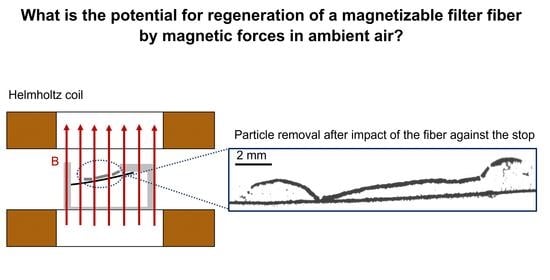
:The potential utilization of magnetic effects in gas particle separation is a current subject of research. This paper demonstrates for the first time that a single magnetizable filter fiber can be deflected by a magnetically induced excitation for a selected combination of parameters, resulting in the removal of deposited particle structures with high detachment levels. A correlation between the magnetic flux density and achieved acceleration to overcome the adhesive forces/strength of the particle structure was determined. The degree of detachment after each regeneration was calculated by comparing the projection area before and after detachment using high-speed images. At a magnetic flux density of B = 38.5 mT, accelerations of maximum a = 105 m·s−2 are achieved, depending on the axial position along the single fiber. The degrees of regeneration achieved at these parameters depend on the amount of fiber loading and on the fiber orientation in the gravitational field. The horizontal orientation of the fiber leads to an increased reattachment of precedingly detached particle structures after deflection compared to a vertical orientation. High particle loading on the fiber results in enhanced detachment by inertia. Under the most favorable process conditions investigated, detachment levels of >90% are achieved.
1. Introduction
Magnetic forces can generally be used in the deposition as well as in the detachment processes of particle structures (regeneration). Either the collectors or the particles or both constituents can be magnetized. The magnetic separation between particle structures and collectors has already been established in the field of solid–liquid separation, and enables the separation of magnetizable particles in the lower submicron size range on an industrial scale [1]. Depending on the particle size and particle concentration, magnetic intensities in a range of approximately B = 0.2–5 T are applied [1,2]. Magnetic filters or grids are widely used in industrial applications, for example in the purification of hydraulic oils, slurries, and liquid pharmaceutical products [1,2,3]. In these processes, mostly magnetizable particles are attracted by magnetic collectors, and thus separated from the liquid or continuous phase. Recent studies show that non-magnetic particles, such as microplastics can also be separated from the fluid phase by “magnetic seed filtration” [4] using a high field strength gradient of B = 0.2–0.5 T [5]. For this method, magnetic particles are added to a suspension containing non-magnetic particles. The magnetic particles agglomerate with the non-magnetic particles to form hetero-agglomerates.
The previous studies explored the enhanced separation by attractive magnetic forces. Other studies from the literature investigated the magnetic motion excitation of membranes and collectors. The field of water treatment shows that magnetically induced membrane vibration can achieve higher flow rates and lower fouling rates [6]. A patent already exists for a vibrating filter in which magnetostrictive materials vibrate a membrane filter through an applied magnetic field to prevent clogging or fouling [7]. However, all of the above-mentioned investigations on magnetically induced particle separation or particle detachment took place in the liquid phase.
The use of magnetic effects, such as magnetically induced motion excitation for the regeneration of single fibers or entire filter media, could also find application in the field of gas-particle separation technologies. Magnetic effects could be used to move entire filter media or individual collectors. While surface filters could be regenerated by the magnetic excitation of an entire medium, the excitation of the single filter fibers would be more conceivable for depth filters. A few studies that deal with the separation of ferromagnetic particles on magnetic filter materials in the gas phase can be found in the literature [8,9]. The magnetically induced detachment (regeneration of fibers) of non-magnetic particles in gas-particle separation technology has not been investigated yet. This study aims to close this gap by showing the potential benefits of the magnetically induced regeneration of a filter in gas-particle separation technologies.
For the fundamental investigation of the novel regeneration concept by magnetic forces, the detachment will be performed using a single ferromagnetic fiber. The fiber is fixed on one side and is magnetized by an external magnetic field (Helmholtz coils), deflected from its starting position and abruptly decelerated by a stop. If the inertial forces acting on the particle agglomerates are stronger than the adhesive forces due to the acceleration of the fiber, the agglomerates can be detached from the fiber. The acceleration of the single fiber depends on the resulting magnetization of the single fiber by the external magnetic field. For a uniform magnetization along the fiber axis, a homogeneous magnetic field is desired. In this study, a Helmholtz coil is used and examined regarding the homogeneity of the magnetic field. There are numerous studies in the literature on the simulation of the magnetic field of Helmholtz coils with COMSOL Multiphysics [10,11,12]. Therefore, in this study, the homogeneity of the magnetic field generated by the coils was simulated using the finite element method (FEM) by COMSOL Multiphysics and was additionally determined experimentally using a Hall probe.
Furthermore, the magnetization of the single fiber was investigated as a function of the applied magnetic field strength. For an exemplarily defined magnetic flux density (B = 38.5 mT), the motion behavior of the single fiber is characterized and the degree of regeneration for a specific particle structure by magnetically induced detachment is calculated.
2. Materials and Methods
2.1. Fiber
The fiber consists of ferritic chromium steel X6Cr17, with material number 1.4016 or AISI 430. The advantage of this soft magnetic material is its ease of remagnetization due to its low coercivity and remanence flux density. The steel has a density of ρ = 7.7 kg dm−3, a Young’s modulus of E = 2.2 × 10¹¹ Pa.
2.2. Particulate Matter
For the generation of particle structures in all detachment experiments, Spheriglass 5000 CP00 from Potters Industry (Malvern, PA, USA) was served as the particulate matter. The glass spheres have a number-based diameter of x50.0 = 1100 nm, a material and bulk density of ρmaterial = 2.46 g/cm3 and ρbulk = 1.28 g/cm3.
2.3. Helmholtz Coils
In this study, a pair of Helmholtz coils (Figure 1) is employed to ensure a homogeneous magnetic field in the region of the investigated single fiber. Additionally, the magnetic field strength can be varied by changing the applied current. The technical parameters of the utilized Helmholtz coil are summarized in Table 1.
Since heat is generated during operation, the coils are cooled by an adjustable flow of cooling water (T = 7 °C) to ensure the longer operation of the measurements. The coils are located in an aluminum housing in order to dissipate the heat well. Cooling was no longer necessary in the later short-time operation (Section 2.7 and Section 2.8).
2.4. Simulation of the Magnetic Field
The magnetic flux density occurring in the intercoil gap at different DC currents (I = 1–3 A) was simulated using the finite element method (FEM) by COMSOL Multiphysics (6.0). The ability of COMSOL to simulate the magnetic properties of Helmholtz coils has been demonstrated in many previous studies [12,13,14]. The simulation of the magnetic field is based on the implemented module “Physics of Magnetic Fields”. The magnetic field observed in this work is assumed to be static in the context of the simulation; the numerical models for its description are based on Maxwell’s differential equations. To determine the magnetic field, the magnetic vector potential A is calculated considering the externally applied current density J and the permeability µ, as follows [15,16]
J = ∇ × (μ−1 ∇ × A)
In this model, the permeability of vacuum, that is, μ ≈ 4π × 10−7 H∙m−1, is used.
The correlation between magnetic flux density B and vector potential A is given by:
B = ∇ × A
The geometry and arrangement of the coils were defined analogously to the real setup (Table 1). Figure 1 shows the geometry of: (a) The Helmholtz coils; and (b) The generated finite element mesh. The coils have an inner diameter of 4 cm and are placed in a distance of 5 cm from each other. An approximately homogeneous magnetic field between the coils results from this geometrical arrangement. Each coil consists of 800 turns. The currents are specified to be parallel for the two coils. The coils are surrounded by an air domain with an outer radius of r = 30 cm to confine the geometry of interest.
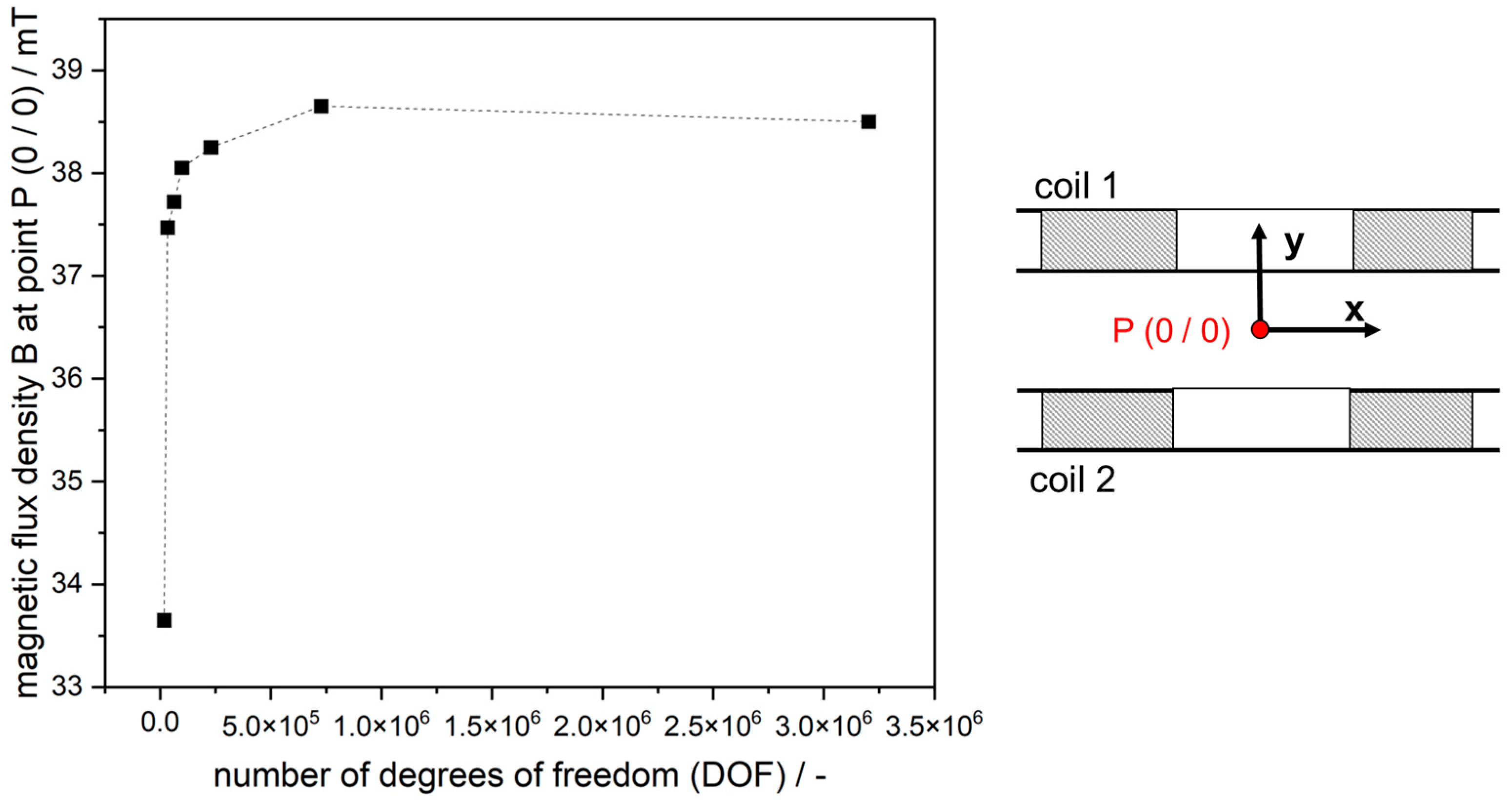
The physics-controlled mesh “extremely fine” was selected for the simulation (Figure 1b). This provided the best correlation of the magnetic flux density curves with the experimental results. Additionally, the solution is independent of the applied mesh (Figure 2). The maximum element size of the used mesh is 0.012 m and the minimum size is 0.12 mm. The mesh consists of 443,637 volume elements, 22,666 surface elements, and 1,066 line elements. The number of degrees of freedom (DOF) is used as a parameter for the fineness of the mesh. Higher values of the DOF represent a finer mesh. For the physics-controlled mesh “extremely fine”, the DOF is 3,203,730.
A mesh independence study was conducted to determine the required fineness of the mesh. The independence is proven when a constant value for the magnetic flux density is provided. Therefore, the mesh size of the physics-controlled mesh was increased from “coarser” (DOF = 18,448) to “extremely fine” (DOF = 3,203,730). In Figure 2, the simulated magnetic flux density at point P (0/0) is related to the number of degrees of freedom. For all simulated points in Figure 2, the residual error is smaller than 10−4. For low DOF values, the magnetic flux density at point P still differs significantly. Only for DOF values higher than 727,688, is the deviation less than 0.3%. Thus, the value of the magnetic flux density tends towards a mesh-independent solution.
2.5. Experimental Determination of the Magnetic Flux Density
In order to verify the actual homogeneity of the magnetic field and to validate the simulation results, a FH51 field strength meter from Magnet Physik Dr. Steingroever GmbH was used to measure the magnetic flux density. The Hall probe detects a voltage difference induced by the magnetic field that is proportional to its field strength or magnetic flux density. The probes have a deviation of +/− 2% according to the manufacturer.
Figure 3 shows, on the right side (b), the schematic measurement in the x and y directions to detect the axial field component of the magnetic flux density. For the accessibility to detect the entire process space anticipated for fiber movement, which is marked with a black square in Figure 3, two Hall probes are used (Figure 3a) to measure the course of the B-field at different current strengths (I = 1–3 A). The transversal probe was positioned parallel to the axis of symmetry (axial direction), and the axial probe was oriented perpendicular to the coil axis (radial direction). The magnetic flux density was measured in steps of 0.5 cm. Comparing the two probes at the same measuring points reveals a deviation of approximately 2%.
2.6. Magnetization of the Single Fiber
By recording a magnetization curve using a MicroMag2900 Series AGM from PMC at the Institute of Functional Interfaces (Karlsruhe Institute of Technology, Karlsruhe, Germany), the magnetization of the ferromagnetic fiber material was determined as a function of the external field strength. Three repeated measurements were performed with a mass of 2 mg of the material. Before each measurement, a section of the fiber was demagnetized by an alternating magnetic field strength of H = +/−400 kA m−1. By recording the magnetization curve, the dependence between the magnetization of the fiber and the applied external field is investigated.
The resulting magnetization curve of the ferromagnetic fiber as a function of the applied external field strength is shown in Figure 4. This magnetization curve is similar to that obtained by Franzreb for the same fiber material 1.4016 [2] (p. 41). Since the field strengths calculated from the magnetic flux densities of the measurements in chapter 3.1 are in the range of about H = 0–30,000 Am−1, this range is shown in detail in an additional diagram on the right side of Figure 4. Within this relevant field strength range, there is an approximately linear relationship between the magnetization and the field strengths selected in the measurements. The remanence flux density of the fiber averaged from three measurements is Hr = 1.9 Am2·kg and the mean coercivity is Hc = 1.12 × 10⁻³ kA·m−1.
2.7. Investigation of Fiber Deflection
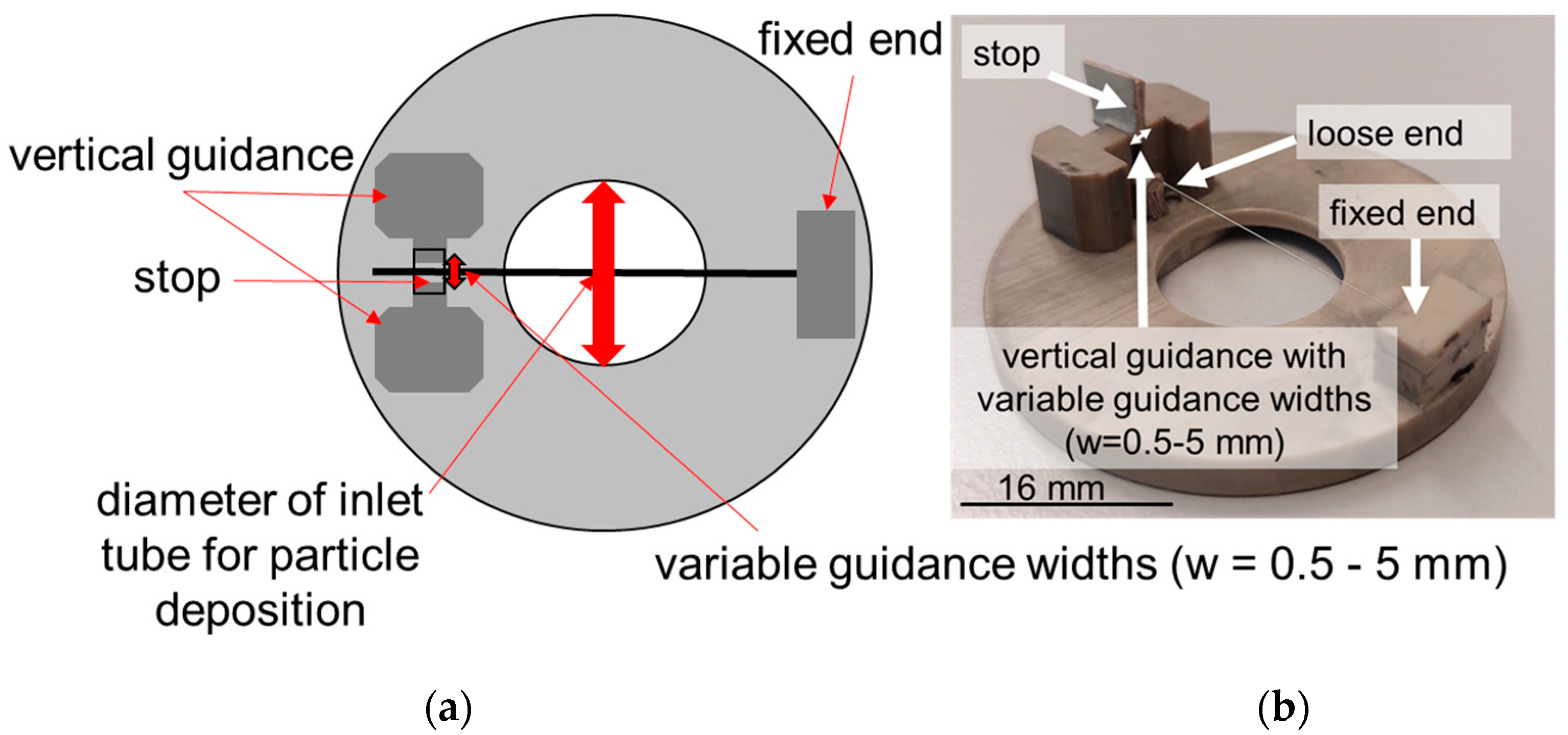
In all measurements, the magnetizable single fiber is fixed at one end in a fiber holder and has a defined start position and stop at the fiber end (see Figure 5). The fiber is positioned in the middle of the Helmholtz coils within the test chamber using the fiber holder (Figure 6). The loose end of the fiber is guided in a vertical direction, and the guide width can vary between w = 0.5 mm and w = 5 mm. As can be seen in Figure 5a, the fiber can only be loaded over a length of about 16 mm, which corresponds to the diameter of the inlet tube.
In the experiments, it has been shown that the orientation of the fiber to the gravity field has an influence on the efficiency of regeneration. Therefore, the fiber motion is investigated for two orientations of the fiber with respect to the gravity field. In the first orientation, the fiber is oriented horizontally. The direction of fiber motion during deflection is against the direction of the gravity field. In the second orientation, the fiber is oriented vertically and the deflection is perpendicular to the gravitational field (see Figure 6).
In the set-up, the magnetic flux density is approximately perpendicular to the fiber axis, so that the fiber is magnetized when the external field with the magnetic intensity of B = 38.5 mT (I = 3 A) is switched on. The characterization of the fiber deflection was conducted at the maximum magnetic intensity studied in Section 2.4 and Section 2.5.
When the magnetic field is switched on, the fiber initially experiences a line force. Due to the fixation, this results in a bearing force and moment as well as a deflection and bending of the fiber. During deflection, the fiber is guided laterally. To improve the detachment of the particle structures from the fiber, which will be investigated in Section 2.8, the loose end of the fiber hits a stop. As a result, the fiber is abruptly decelerated and the particles will be detached from the fiber due to inertia.
The degree to which the motion of the fiber is influenced by the guiding assembly was verified by measurements at different guiding widths of w = 0.5 mm and w = 5 mm and without guidance. In addition, the fiber movement was investigated both with and without stop. In these investigations, the unloaded single fiber was used for all experiments. Additionally, the impact of the particle loading on the fiber movement was explored for selected conditions (w = 0.5 mm, with stop). The fiber was loaded with Spheriglass in a certain area (l~1.5 cm). The particles are deposited along the fiber-cross section corresponding to the diameter of the inlet pipe. The particle material and experimental set-up are described in detail in Chapters 2.2 and 2.8. The loading height of the particle structure was h = 0.5 mm (tloading = 20 min).
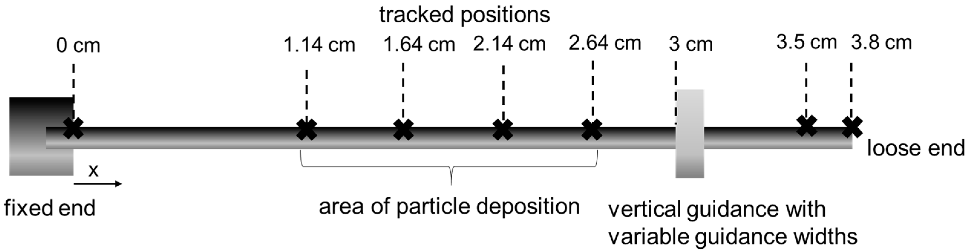
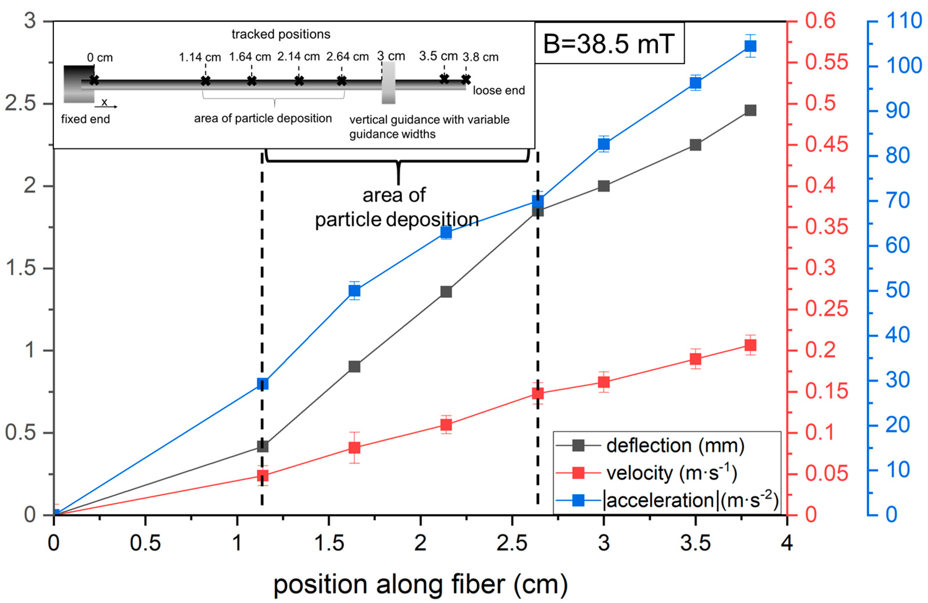
The fiber motion is mainly observed in the particle deposition section of the fiber. The field of view (FOV) was 6 × 17.4 mm. Using high-speed imaging (X-PRI by AOS Technology, lens: NAVITAR 12x) at a frame rate of 3228 fps, the deflection, velocity, and acceleration of the fiber are evaluated at defined time steps at the positions indicated in Figure 7.
The temporal deflection y of the fiber with the initial position y0 is tracked at defined positions with the open source software Tracker 6.1.0 (Physics Java Framework) resulting in a position–time graph. The velocity curves are calculated from the raw data of the position time curve of the fiber deflection. Since the smallest deviations during tracking lead to large scattering of the velocity values, these are averaged over ten values. The acceleration is calculated by differentiating the averaged velocity values.
2.8. Investigation of Particle Detachment
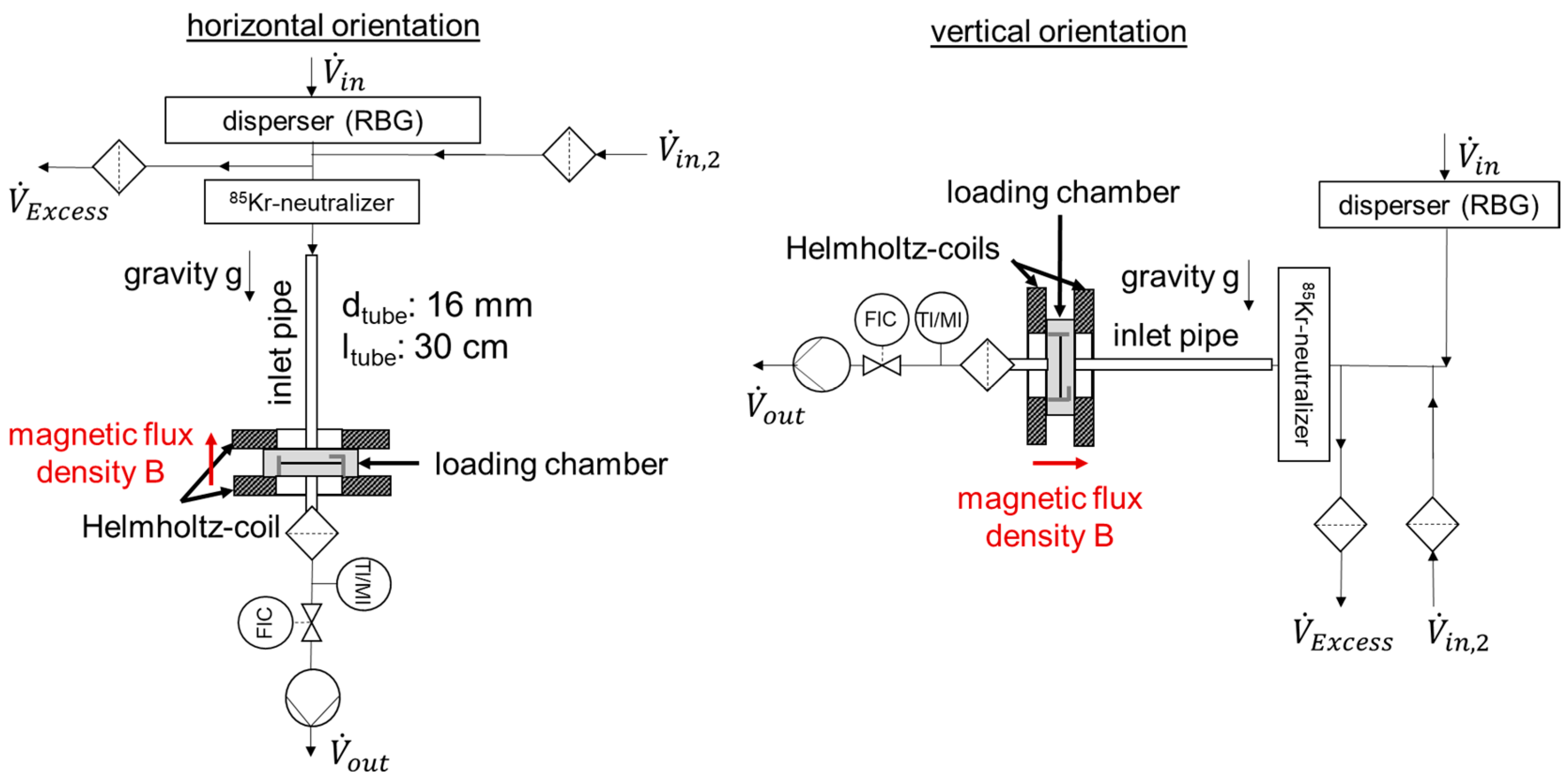
In order to investigate the efficiency of particle detachment as a function of the orientation of the fiber to the gravitational field, the fiber was mounted in the fiber holder and positioned either horizontally or vertically for particle loading in the measuring chamber between the two coils (Figure 8).
The particulate material (Spheriglass) is dispersed into an air volume flow of Vdis = 9.73 l·min−1 using a disperser (RBG 1000) at a dispersion pressure of p = 1 bar. Before entering a 85Kr-neutralizer to ensure the constant charge distribution of the particles, the volume flow is divided into Excess and in,2. The volume flow is out after the loading chamber is controlled with an MFC. The volume flow rates set in the various tests are shown in Table 2. The gas-borne particle material is applied to the single fiber via an inlet tube (ltube = 30 cm).
Inside the inlet tube is a built-in flow straightener, which assures a uniform local inflow velocity. The diameter of the inlet and outlet tubes is 16 mm, ensuring a uniform flow around the fiber. The distance between both tubes and the fiber is also d = 16 mm. The particle structures are generated at a constant raw gas concentration. Varying the loading time obtains two different loading heights on the fiber. The adjusted parameters for the loading and the subsequent deflection of the fiber are summarized in Table 2.
The magnetic flux density generated is adjusted by applying different current intensities. To detach the particle structures, a current of I = 3 A is set, which corresponds to a magnetic flux density of B = 38.5 mT. The fiber is deflected as soon as the circuit of the series-connected coils is closed. The voltage rise is monitored with an oscilloscope UTD2052 CEL from UNI-T.
To evaluate the particle detachment, the projection surface of the particle structure is imaged with the same high-speed camera that was used to observe the fiber deflection. The frame rate and the field of view were identical to the measurements in Section 2.7
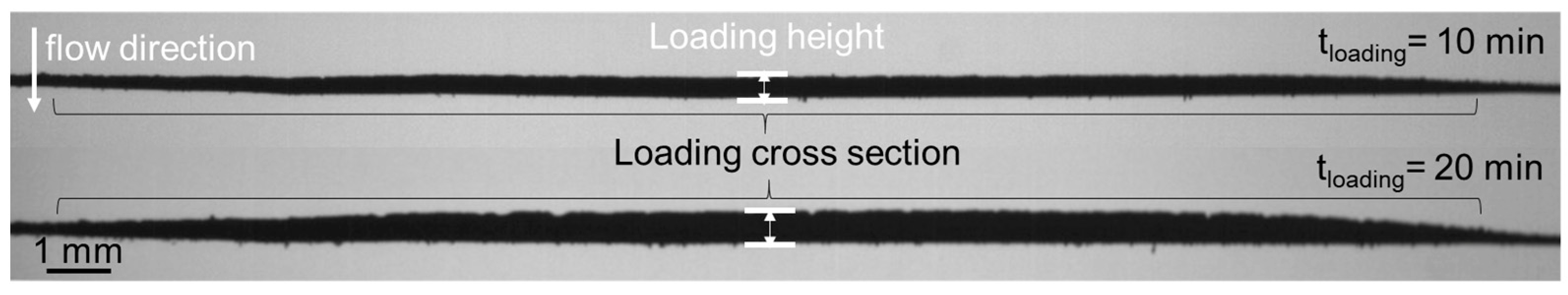
Figure 9 shows the generated particle structure at the two loading times. The heights of the particle structures vary between approximately h = 0.25 mm (tloading = 10 min) and approximately h = 0.5 mm (tloading = 20 min). Both particle structures were generated at an incident flow velocity of v = 1.65 m·s−1 (St = 5.66) and are rather compact because the particle structure becomes more compact with an increasing Stokes number, as demonstrated by several studies [17,18]. As shown in Figure 9, the particles are deposited almost uniformly along the fiber axis, which results in a nearly uniform height.
Since the FOV is selected to be larger than the nominal loading area, the decreasing height of the particle structure can be seen at the edges. The particles accumulate preferentially on the inflow side. On the downstream side, only isolated dendrites are present, so it can be assumed that the deposition is mainly dominated by inertia.
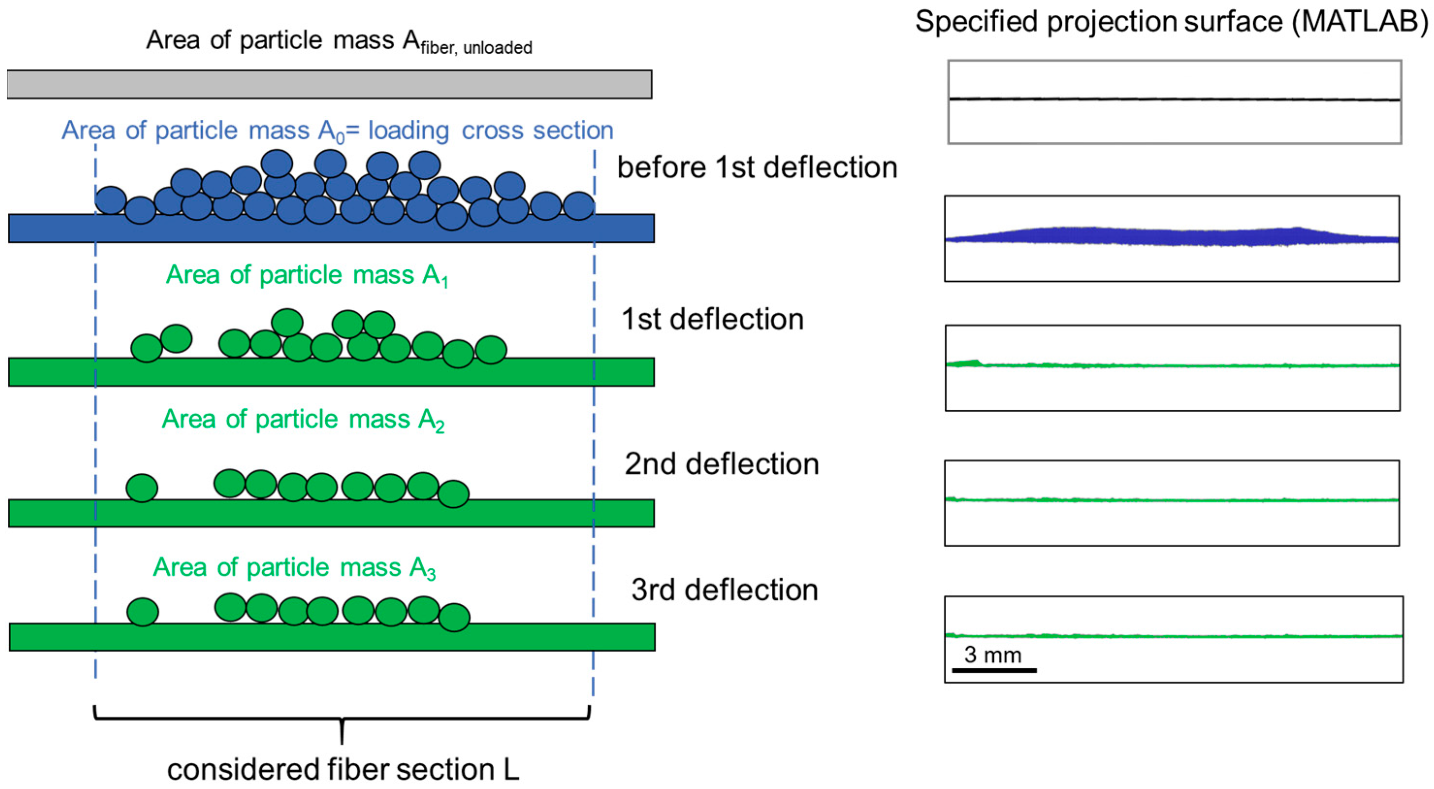
The projection areas of the fiber and particle structure are determined applying a MATLAB® image analysis R2022b. The pictures are binarized by using the method of Otsu [19]. After binarization, the bright pixels are counted and converted to the projection area using a scale. Before loading the fiber with particulate material, the projection area of the unloaded fiber is determined. After the loading of the fiber with the glass spheres, the projection area is composed of the fiber and the particle deposit. The projection area is determined before the magnetically induced detachment and also after each deflection of the fiber (see Figure 10).
By subtracting the projection area A0+n after fiber deflection from the initially loaded fiber A0, the detached area can be quantified. The projection area of the unloaded fiber AFiber, unloaded is always subtracted when determining the projection area of the particle loading. The degree of regeneration results from the relation of the detached projection area (A0 − A0+n) to the initially existing area A0. The degree of regeneration rn can be calculated for each individual fiber deflection in accordance with Equation (3). It describes the percentage of the cumulative detached projection area after each fiber deflection.
3. Results and Discussion
3.1. Magnetic Field
Figure 11 shows the simulated and the experimentally determined magnetic flux density along the symmetry axis at different selected direct current strengths. The results reveal that the simulative results are in good agreement with the experimental data. Differences in magnetic flux density of about 1% mainly occur at y > +/−1.5 cm. These deviations exist at all current strengths and it seems that from y = +/−1.5 cm, the homogeneity of the field decreases slightly. Since the fiber only deflects a maximum of 5 mm in the y direction, these deviations are outside the range of motion of the fiber (region of interest for fiber movement).
Figure 12 shows the three-dimensional plot of the normalized axial component of the magnetic flux density. Due to accessibility, measurements were made from the axial and radial directions using the two Hall probes. In addition, an auxiliary line shows the position of the fiber, as used later on during the experiments. Since the fiber is deflected by a maximum of 5 mm, homogeneity in the range from y = −0.5 cm to 0.5 cm in the axial direction is crucial (a). In the radial direction, homogeneity along the fiber axis is decisive. Due to the geometry of the coils, only a total length of x = 2 cm (−1 cm to +1 cm) could be gridded here (b).
As can be seen in Figure 12a, the magnetic flux density is approximately constant from x = −2 cm to +2 cm in the radial direction and decreases towards the edges. The decrease is typical for a Helmholtz coil, since a constant magnetic flux density only exist over a certain area.
In axial direction (y = −0.5 cm to +0.5 cm), the deviations of the measuring points are about 2%. This deviation is probably caused by measurement errors in the exact positioning of the probes at the measuring points or due to a possibly not exactly parallel alignment of the coils to each other. Figure 12b shows a maximum decrease in magnetic flux densities of 3% in the radial direction. The deviation is probably due to inaccuracies in the positioning of the probes or the measurement deviation between the probes. Due to the small deviations, an almost homogeneous magnetic flux density can be assumed within the process space, which is relevant to the fiber movement.
3.2. Characterization of the Fiber Deflection and Acceleration
If a ferromagnetic body (here a fiber) is placed in a homogeneous external magnetic field, this body can rotate and align itself in the field direction and experiences a torque. In this study, the fiber is oriented approximately perpendicular to the magnetic field and is clamped at one side. The arrangement corresponds to a bending beam fixed on one side. The fixation results in a bearing force and moment, as well as deflection and bending of the fiber. The relationship between the bending and the magnetization M can be described by balancing the bending moment of the wire and the torque T [20]. The magnetic torque is defined for an arbitrary body of volume V with uniform magnetization M surrounded by a uniform induction field B in a vacuum and the angle between B and M as follows [21]
Equation (4) reveals that the angle between the magnetization and the B-field influences the strength of the torsional moment. If the angle were 0, as in the case of an ideal orthogonal alignment of the fiber axis to the B-field (Figure 13A), there would be no moment and no deflection of the fiber. If there was a slight misalignment of the fiber axis to the B-field (alpha not equal to 90°), there would be a predominant magnetization in the axial direction (Figure 13B). The greater the angle, the greater the moment. A theoretical description of the deflection by a homogeneous external magnetic field was presented in [22] for a ferromagnetic cantilevered rod clamped at one end.
Since in this study the fiber was demagnetized before it was magnetized by the external magnetic field, it is assumed that no remanence is present in the axial direction. The remanence occurring after the repeated magnetization of the fiber could also not be directly verified. Nevertheless, several fibers were used to experimentally check if the uncertainties of a possible initial magnetization, the impact of misalignment to the magnetic field or the remanence by alternating field have a different effect on the deflection behavior.
To check the influence of potentially different initially magnetic states, nine samples of demagnetized (fibers) were used (Figure 14). Since the fiber is only fixed at one end and has a loose end, it is not possible to position it exactly perpendicular to the magnetic field. The initial angle between the fiber axis and the direction of the B-field varied in the range of about β = 87.4–89.5. Figure 14 shows the maximum deflection (tracked at position x = 2.64 cm) of the nine samples. The maximum deflection of the fiber is plotted as a function of angle β. As mentioned before, the initial angle of fiber rotation varies in the range of approximately β = 87.4–89.5 (Figure 14). Despite this variation, the evaluated maximum deflections (tracked at position x = 2.64 cm) are in a similar size range. It seems that the misalignment of the fiber relative to the field lines and the uncertainties of the magnetization have a minor influence on the measurement results.
Figure 15 shows an example of the time evolution of the fiber deflection at the fiber position x = 2.64 cm in relation to varied parameters (guidance widths w, stop, particle loading on the fiber). Since the deflections for the horizontal and vertical orientation of the fiber were comparable, only the results of the horizontal fiber orientation will be presented in the following. The diagram illustrates the fiber deflection over time at the guidance widths w = 0.5 mm and w = 5 mm, respectively, and both with and without the collision of the fiber against the stop. To evaluate the influence of the guidance, the free fiber movement without guidance and stop is also shown (black curve). In addition, the movement of the fiber was investigated when it was loaded with particles (tloading = 20 min, h = 5 mm, w = 0.5 mm) (blue curve).
In all six cases presented in Figure 15, the deflection increases to a maximum and then starts to oscillate periodically. Due to frictional forces, the amplitude decreases with time for all trajectories, representing a damped harmonic oscillation. If the fiber is deflected and not arrested by a stop, the amplitude is more than twice as large as when it collides against the stop. The guidance and the different guidance widths do not have a large influence on the fiber vibration, since the motion patterns for deflection with and without guidance are comparable. When colliding against the stop, the duration is 3.3 times shorter. If the fiber is loaded with glass spheres of a loading height of h = 5 mm, the fiber behaves approximately as without particle loading.
The deflection, velocity, and acceleration curves for measurements with and without stop for a guide width of w = 0.5 mm are shown in Figure 16. The velocity curves are calculated from the raw data of the position time curve of the fiber deflection. In Figure 16, the moving average curve based on ten values for velocity is presented. The acceleration is calculated with the moving average values of velocity. With and without the stop, the velocity and acceleration increase similarly during the fiber deflection. Without a stop, the velocity is zero at the time of maximum deflection and the acceleration is approx. 40 m·s−2. With a stop, the maximum velocity of v = 0.19 m·s−1 is reached at the time of impact. Since the analysis is performed at the position x = 2.64 cm, an increase in the deflection is still observed after the impact (t > tstop). This can be attributed to a deflection of the fiber. Consequently, the velocity and acceleration do not decrease abruptly at t = tstop. The maximum velocity is v = 0.15 m·s−1 and the maximum acceleration is a = −71 m·s−2.
Figure 17 shows the maximum deflections and absolute accelerations at different positions along the horizontally positioned fiber axis (with stop, w = 0.5 mm, w/o particle loading). Due to the increasing lever arm, the deflection, velocity, and acceleration increase with distance from the fiber fixation. In the range relevant for particle detachment, the maximum velocities and accelerations differ in a range of approximately v = 0.05–0.015 m·s−1 and |a| = 30–70 m·s−2.
3.3. Particle Detachment
Figure 18 exemplarily presents the transient detachment processes of the particle structures at accelerations of |a| = 30–70 m·s−2 for the two loading heights of the single fiber in the horizontal orientation of the fiber. After the fiber has been loaded with particles, the fiber is deflected several times. Figure 18 presents the first deflection of the fiber of a maximum of three deflections (with stop, w = 0.5 mm). The detachment takes place without additional flow through the test chamber.
Until the moment of impact, the particle structure does not detach from the fiber. As soon as the fiber collides against the stop, a continuous crack forms within the particle structure parallel to the fiber surface. The fracture occurs between the particle–particle contact points rather than at the particle–fiber contact points. This suggests that due to different local packing densities within the deposited particle structure [23,24], which decreases close to the fiber than further away, the upper particle layers are more likely to be removed due to the lower bonding forces (mainly, V.d.W. forces).
Due to the acting inertial forces, the detached particle structure is flung upwards against the gravitational force and partially disintegrates into smaller fragments. Due to the increased load of the higher particle structure, stronger inertial forces are applied during detachment, and the particle structure travels further upwards from the fiber before it settles downwards due to gravity. Ultimately, a thin residual structure resembling a uniform homogeneous particle layer remains on the fiber for both loading heights. With the horizontal fiber arrangement, a reattachment of already detached particle structures often occurred during the measurements in the final settling phase. Thus, the detachment of particle structures in vertical fiber arrangement was also investigated.
At the vertical fiber orientation (Figure 19), the particle structure also remains on the fiber during deflection until the fiber hits the stop. Upon collision, the particle detaches from the fiber as a continuous structure. Fragmentation into small and large fragments, as in the case of horizontal fiber orientation, is not observed. Possibly, the gravity force acts against the inertial force of the particle structure relevant for particle detachment at the horizontal orientation. The vertical orientation of the fiber produces fewer small agglomerates, which is of great importance for the prevention of emissions in the fine dust range.
Even at the vertical arrangement, a residual structure remains on the fiber due to preferential breaking of particle–particle contacts close to the fiber. A reattachment, as found for the horizontal arrangement (see Figure 18), was not observed in the vertical fiber orientation.
Since a residual layer remains after the first deflection (and partially detached structures are reattached), whether the degree of regeneration increases with repeated deflections should be investigated. The degrees of regeneration calculated from the projection surfaces are plotted in Figure 20 over the number of deflections for both orientations of the single fiber.
In all four measurements, the majority of the particle layer is already detached from the fiber after the first deflection. The increase in the degree of regeneration is smallest between the second and third deflection and is only present for the horizontal fiber alignment to gravity. Presumably, there is an optimum between the achievable degree of regeneration and the energy input for the investigated parameters.
When the fiber is oriented horizontally, the average degree of regeneration of the lower structures is 92% (square blue points). With the higher structure, disproportionately more particle material remains on the fiber, resulting in a degree of regeneration of 76% (round blue points). The likelihood of detached particle structures reattaching to the fiber increases with increasing particle mass due to greater inertia. This behavior was observed especially in the experiments with higher loading heights, which led to the large scatter and the lower degree of regeneration. It should be noted that the lower degree of regeneration is not due to a generally higher residual layer on the fiber, but is caused by reattached agglomerates, which are detached again during the next deflection.
The second deflection removes a further 8.8% of the residual structure from the fiber, and after the third deflection, a further 1.9% is removed. Consequently, the degree of regeneration is 87% after three deflections.
In contrast, with the low particle structure, only 3.2% is removed by the second deflection and 0% by the third deflection, resulting in a regeneration degree of 96%.
When the fiber is oriented vertically, the initial degree of regeneration at the lower structure height is 84% (square red points). By deflecting the fiber again, the degree of regeneration is increased by 2%. This is significantly lower compared to the increase in the degree of regeneration for the horizontal fiber orientation. In the case of the higher fiber loading (round red points), a degree of regeneration of 93% is achieved after the first deflection, which cannot be increased by further deflections.
4. Conclusions and Outlook
This study demonstrated for the first time that a single magnetizable filter fiber can be deflected by a magnetically induced excitation for a selected combination of parameters (e.g., B = 38.5 mT, lF = 3.8 cm, ferromagnetic fiber of AISI 430). It has also been shown that particle structures already deposited on the fiber can be removed with a high degree of regeneration.
The main results of this study are:
- A correlation between the magnetic flux density and achieved acceleration to overcome the adhesive forces/strength of the particle structure was determined. At a magnetic flux density of B = 38.5 mT, accelerations of |a| = 30–70 m·s−2 were achieved, depending on the position along the fiber;
- The experiments have shown that the regeneration of compact particle structures mainly results in the fracture of the contact points between the individual particles;
- The achieved degrees of regeneration at these parameters depend on fiber loading and fiber orientation to the gravity field. For the horizontal fiber orientation, after three deflections of the fiber against a stop, regeneration degrees of 96% at low fiber loadings (h = 0.25 mm) and of 86% at an increased fiber loading (h = 0.5 mm) were found. Especially at the horizontal fiber orientation with a higher particle structure, a reattachment of already detached particle structures was observed. Therefore, the degree of regeneration in the first regeneration event is lower than in the case of the lower particle structure. In addition, high fragmentation of the detached particle structure was observed at this orientation;
- For the vertical fiber orientation, regeneration degrees of 87% for the lower particle structure (h = 0.25 mm) and regeneration degrees of 93% for the higher particle structure (h = 0.5 mm) were determined. Due to the higher inertia of the higher particle structure (h = 0.5 mm), detachment occurs more easily than with the lower particle structure. Additionally, only slight fragmentation was observed in the vertical orientation of the fiber;
- Regardless of the orientation of the fiber, the degree of regeneration is only slightly improved after the second deflection. Consequently, there appears to be an optimum between the achievable degree of regeneration and the energy consumption for the investigated parameters.
Based on these findings, future studies will investigate the detachment behavior of particle structures that differ in material and morphology from a single fiber.
It is expected that diffusive structures will exhibit poorer detachment behavior due to their lower weight or inertia (at comparable structure heights). Additional inflow during regeneration could further improve detachment. Furthermore, the effectiveness of magnetic detachment should also be investigated at lower magnetic flux densities to find the optimum of energy consumption.
Author Contributions
Conceptualization, J.S.; methodology, J.S.; software, J.S.; validation, J.S., J.M. and A.D.; investigation, J.S.; writing—original draft preparation, J.S.; writing—review and editing, J.S., J.M. and A.D.; visualization, J.S.; supervision, J.M. and A.D.; project administration, A.D.; All authors have read and agreed to the published version of the manuscript.
Funding
This research received no external funding.
Data Availability Statement
The data presented in this study are available on request from the corresponding author.
Acknowledgments
We acknowledge the collaboration of Raquel Bischoff and Leon Tempelfeld for their help in conducting the experiments.
Conflicts of Interest
The authors declare no conflict of interest.
References
- Svoboda, J. Magnetic Techniques for the Treatment of Materials; Kluwer Academic Publishers: Dordrecht, The Netherlands, 2004. [Google Scholar]
- Franzreb, M. Magnettechnologie in der Verfahrenstechnik Wässriger Medien; KIT: Karlsruhe, Germany, 2003. [Google Scholar]
- Franzreb, M.; Holl, W. Phosphate removal by high-gradient magnetic filtration using permanent magnets. IEEE Trans. Appl. Supercond. 2000, 10, 923–926. [Google Scholar] [CrossRef]
- Rhein, F.; Scholl, F.; Nirschl, H. Magnetic seeded filtration for the separation of fine polymer particles from dilute suspensions: Microplastics. Chem. Eng. Sci. 2019, 207, 1278–1287. [Google Scholar] [CrossRef]
- Menzel, K.; Windt, C.W.; Lindner, J.A.; Michel, A.; Nirschl, H. Dipolar openable Halbach magnet design for High-Gradient Magnetic Filtration. Sep. Purif. Technol. 2013, 105, 114–120. [Google Scholar] [CrossRef]
- Bilad, M.R.; Mezohegyi, G.; Declerck, P.; Vankelecom, I.F. Novel magnetically induced membrane vibration (MMV) for fouling control in membrane bioreactors. Water Res. 2012, 46, 63–72. [Google Scholar] [CrossRef] [PubMed]
- Yang, F.-R.; Chen, Y.-F.; Lin, S.-A. Vibration Filter: Application. 2006. Available online: https://patents.justia.com/patent/20060138037 (accessed on 28 March 2023).
- Zhao, L.; Li, X.; Sun, W.; Ye, Z.; Huang, J.; Zhang, G.; Pan, J.; Cai, J. Experimental study on bag filtration enhanced by magnetic aggregation of fine particles from hot metal casting process. Powder Technol. 2018, 327, 255–266. [Google Scholar] [CrossRef]
- Zhou, F.; Diao, Y.; Wang, R.; Yang, B.; Zhang, T. Experimental study on PM2.5 removal by magnetic polyimide loaded with cobalt ferrate. Energy Built Environ. 2020, 1, 404–409. [Google Scholar] [CrossRef]
- International Conference on Sustainable Energy and Environmental; Zhang, Q.; Song, S.; He, P.; Li, H.; Mi, H.-Y.; Wei, W.; Li, Z.; Xiong, X.-Z.; Li, Y. Motion Control of Magnetic Microrobot Using Uniform Magnetic Field. IEEE Access 2020, 8, 71083–71092. [Google Scholar] [CrossRef]
- Zatonov, I.; Baranov, P.; Kolomeycev, A. Magnetic field computation and simulation of the coil systems using Comsol software. MATEC Web Conf. 2018, 160, 01006. [Google Scholar] [CrossRef]
- Nismayanti, A.; Jannah, H.; Rugayya, S.; Maskur; Adawiyah, R. Helmholtz coils model as pulsed electromagnetic field therapy devices for fracture healing using comsol Multiphysics. J. Phys. Conf. Ser. 2021, 1763, 12060. [Google Scholar] [CrossRef]
- Tschöpe, A. Prozessintensivierung Elektrochemischer Reaktionssysteme Mittels Einer Magnetisch Stabilisierten Wirbelbettelektrode; Karlsruher Institut für Technologie (KIT): Karlsruhe, Germany, 2021. [Google Scholar] [CrossRef]
- Baranova, V.E.; Baranov, P.F. The Helmholtz coils simulating and improved in COMSOL. In Proceedings of the 2014 Dynamics of Systems, Mechanisms and Machines (Dynamics), Omsk, Russia, 11–13 November 2014; pp. 1–4. [Google Scholar]
- COMSOL. Magnetostatics, Theory. 2019. Available online: https://www.comsol.com/multiphysics/magnetostatics-theory (accessed on 23 August 2022).
- Nolting, W. Grundkurs theoretische Physik, 10th ed.; Springer Spektrum: Berlin/Heidelberg, Germany, 2013. [Google Scholar]
- Kasper, G.; Schollmeier, S.; Meyer, J. Structure and density of deposits formed on filter fibers by inertial particle deposition and bounce. J. Aerosol Sci. 2010, 41, 1167–1182. [Google Scholar] [CrossRef]
- Poggemann, L.; Meyer, J.; Dittler, A. Experimental Detection of Particle Structures Detachment from a Stretch-able Single Fiber during Multiple Consecutive Stretching Cycles. Separations 2022, 9, 168. [Google Scholar] [CrossRef]
- Otsu, N. A threshold selection method from gray-level histograms. IEEE Trans. Syst. Man Cybern. 1979, 9, 62–66. [Google Scholar] [CrossRef]
- Adhikari, R.; Kaundal, R.; Sarkar, A.; Rana, P.; Das, A.K. The cantilever beam magnetometer: A simple teaching tool for magnetic characterization. Am. J. Phys. 2012, 80, 225–231. [Google Scholar] [CrossRef]
- Gray, D.E. (Ed.) American Institute of Physics handbook, 3rd ed.; McGraw-Hill: New York, NY, USA, 1982. [Google Scholar]
- Gerbal, F.; Wang, Y.; Lyonnet, F.; Bacri, J.-C.; Hocquet, T.; Devaud, M. A refined theory of magnetoelastic buck-ling matches experiments with ferromagnetic and superparamagnetic rods. Proc. Natl. Acad. Sci. USA 2015, 112, 7135–7140. [Google Scholar] [CrossRef] [PubMed]
- Lehmann, M.J. Untersuchungen zur Struktur und zur Beladungskinetik von Tiefenfiltern; KIT Scientific Publishing: Karlsruhe, Germany, 2005. [Google Scholar] [CrossRef]
- Schollmeier, S. Beladungskinetik von Faserfiltern-Beladungskinetik einzelner Filterfasern. Ph.D. Thesis, University of Karlsruhe, Karlsruhe, Germany, 2008. [Google Scholar]
Figure 1.
Geometry (a) of the Helmholtz coils and the mesh (b).

Figure 2.
Mesh independence study: magnetic flux density in relation to the number of degrees of freedom.
Figure 2.
Mesh independence study: magnetic flux density in relation to the number of degrees of freedom.

Figure 3.
Experimental setup for the determination of the axial component of the magnetic flux density with different Hall probes (a); Schematic illustration of the axial (blue dots) and radial measurement (red dots) of the magnetic flux density exemplarily with the transversal probe (b).
Figure 3.
Experimental setup for the determination of the axial component of the magnetic flux density with different Hall probes (a); Schematic illustration of the axial (blue dots) and radial measurement (red dots) of the magnetic flux density exemplarily with the transversal probe (b).

Figure 4.
Magnetization curve of the ferromagnetic single fiber.

Figure 5.
Schematic top view (a) and picture of the fiber holder (b).

Figure 6.
Horizontal and vertical orientation of the single fiber.

Figure 7.
Tracked positions along the fiber axis to determine local deflection, velocity, and acceleration.
Figure 7.
Tracked positions along the fiber axis to determine local deflection, velocity, and acceleration.

Figure 8.
Schematic drawing of the two experimental set-ups.

Figure 9.
Investigated particle structure before magnetically induced detachment at two different loading times.
Figure 9.
Investigated particle structure before magnetically induced detachment at two different loading times.

Figure 10.
Determination of the degree of regeneration.

Figure 11.
Magnetic flux density determined in axial direction (a) and radial direction (b).

Figure 12.
Spatial presentation of the magnetic flux density in radial (a) and axial (b) measuring direction.
Figure 12.
Spatial presentation of the magnetic flux density in radial (a) and axial (b) measuring direction.

Figure 13.
Schematic drawing of the alignment of magnetization to the B-field if the fiber is perpendicularly orientated to the magnetic field (A) or has a misalignment to the field (B).
Figure 13.
Schematic drawing of the alignment of magnetization to the B-field if the fiber is perpendicularly orientated to the magnetic field (A) or has a misalignment to the field (B).

Figure 14.
Schematic drawing of the initial position of the fiber before and after deflection (a) and range of angles between fiber axis and magnetic field correlated to the maximum deflection at one tracked position (b).
Figure 14.
Schematic drawing of the initial position of the fiber before and after deflection (a) and range of angles between fiber axis and magnetic field correlated to the maximum deflection at one tracked position (b).

Figure 15.
Effect of vertical guidance and particle loading on the fiber deflection at position 2.64 cm for different guidance widths w/and w/o stop.
Figure 15.
Effect of vertical guidance and particle loading on the fiber deflection at position 2.64 cm for different guidance widths w/and w/o stop.

Figure 16.
Temporal evolution of the velocity and acceleration of the fiber at x = 2.64 cm.

Figure 17.
Local determination of deflection, velocity, and acceleration along the fiber axis.

Figure 18.
Temporal development of magnetically induced particle detachment from a fiber in horizontal orientation for a low and high particle structure, respectively, for the first deflection event.
Figure 18.
Temporal development of magnetically induced particle detachment from a fiber in horizontal orientation for a low and high particle structure, respectively, for the first deflection event.

Figure 19.
Temporal development of magnetically induced particle detachment for a low and high particle structure from a fiber in vertical orientation for the first deflection event.
Figure 19.
Temporal development of magnetically induced particle detachment for a low and high particle structure from a fiber in vertical orientation for the first deflection event.

Figure 20.
Degree of regeneration as a function of the number of deflections for a high and low particle structure.
Figure 20.
Degree of regeneration as a function of the number of deflections for a high and low particle structure.


Table 1.
Technical parameters of the applied Helmholtz coils.
| Technical Parameters | Values |
|---|---|
| Diameter of the coil wires/mm | 0.8 |
| Number of turns/- | 800 |
| Electrical resistances of the coils/Ω | 9.4 |
| Height of the coil/cm | 2 |
| Distance between the coils/cm | 5 |
| Inner radius of the coil winding/cm | 4 |
| Outer radius of the coil winding/cm | 6.75 |
Table 2.
Experimental parameters for the particle deposition and detachment.
| Parameters | Values |
|---|---|
| /l·m−3 | 9.73 |
| /l·m−3 | 15.17 |
| /l·m−3 | 4.9 |
| /l·m−3 | 20 |
| /mg h−1 | 565 |
| B/mT | 38.5 |
Disclaimer/Publisher’s Note: The statements, opinions and data contained in all publications are solely those of the individual author(s) and contributor(s) and not of MDPI and/or the editor(s). MDPI and/or the editor(s) disclaim responsibility for any injury to people or property resulting from any ideas, methods, instructions or products referred to in the content. |
© 2023 by the authors. Licensee MDPI, Basel, Switzerland. This article is an open access article distributed under the terms and conditions of the Creative Commons Attribution (CC BY) license (https://creativecommons.org/licenses/by/4.0/).
Share and Cite
MDPI and ACS Style
Szabadi, J.; Meyer, J.; Dittler, A. Particulate Matter Detachment from a Magnetizable Single Fiber Applying Magnetic Forces in Ambient Air. Separations 2023, 10, 297. https://0-doi-org.brum.beds.ac.uk/10.3390/separations10050297
AMA Style
Szabadi J, Meyer J, Dittler A. Particulate Matter Detachment from a Magnetizable Single Fiber Applying Magnetic Forces in Ambient Air. Separations. 2023; 10(5):297. https://0-doi-org.brum.beds.ac.uk/10.3390/separations10050297
Chicago/Turabian StyleSzabadi, Julia, Jörg Meyer, and Achim Dittler. 2023. "Particulate Matter Detachment from a Magnetizable Single Fiber Applying Magnetic Forces in Ambient Air" Separations 10, no. 5: 297. https://0-doi-org.brum.beds.ac.uk/10.3390/separations10050297
Note that from the first issue of 2016, this journal uses article numbers instead of page numbers. See further details here.