Review

Metal–Organic Frameworks as Key Materials for Solid-Phase Microextraction Devices—A Review

by
Adrián Gutiérrez-Serpa
1,†,
Idaira Pacheco-Fernández
1,†,
Jorge Pasán
2 and
Verónica Pino
1,3,*
1
Department of Chemistry, Analytical Division, Universidad de La Laguna, 38206 Tenerife, Spain
2
X-ray and Molecular Lab, Department of Physics, Universidad de La Laguna, 38206 Tenerife, Spain
3
University Institute of Tropical Diseases and Public Health, Universidad de La Laguna, 38206 Tenerife, Spain
*
Author to whom correspondence should be addressed.
Those authors contributed equally to this work.
Submission received: 2 August 2019 / Revised: 26 August 2019 / Accepted: 6 September 2019 / Published: 2 October 2019
(This article belongs to the Special Issue Advances in Solid-Phase Microextraction)

Abstract

:
Metal–organic frameworks (MOFs) have attracted recently considerable attention in analytical sample preparation, particularly when used as novel sorbent materials in solid-phase microextraction (SPME). MOFs are highly ordered porous crystalline structures, full of cavities. They are formed by inorganic centers (metal ion atoms or metal clusters) and organic linkers connected by covalent coordination bonds. Depending on the ratio of such precursors and the synthetic conditions, the characteristics of the resulting MOF vary significantly, thus drifting into a countless number of interesting materials with unique properties. Among astonishing features of MOFs, their high chemical and thermal stability, easy tuneability, simple synthesis, and impressive surface area (which is the highest known), are the most attractive characteristics that makes them outstanding materials in SPME. This review offers an overview on the current state of the use of MOFs in different SPME configurations, in all cases covering extraction devices coated with (or incorporating) MOFs, with particular emphases in their preparation.

Graphical Abstract

1. Overview on Metal–Organic Framework

Metal–organic frameworks (MOFs) are solids constituted of inorganic metal ions (or metallic clusters) and organic linkers connected by coordination bonds. The metal ions act as nodes or centers and the organic linkers act as a bridge between them, forming a complex bi-dimensional or three-dimensional net. Nodes and ligands are termed secondary building units (SBUs). Depending on the coordination sphere of the inorganic SBU, the organic SBU used, and their connectivity, the topology, geometry, and properties of the resultant material will vary significantly [1,2,3,4]. Metal–organic frameworks are a subclass of the more general coordination polymers, because they include only those materials with permanent porosity.
The design and synthesis of MOFs rely on reticular chemistry. This approach allows the design of specific structures by the selection of the inorganic and organic SBUs identifying how the nodes and the linkers interact to form the network [4,5]. While the inorganic SBU dictates the node connectivity (usually as a polyhedron where the vertices are the connectivity points), the organic linker indicates the number of nodes that will be interconnected, being necessary, at least, the use of a ditopic linker (linear connector). Figure 1 shows several representative examples of MOFs structures and their respective SBUs. One of the most representative examples is the family of isoreticular metal–organic frameworks (IRMOFs). This group of MOFs present the same topology and skeleton but different functionalization and pore dimensions due to changes introduced in the organic linker, such as increasing its length or by the incorporation of different functional groups [6].
The design of a MOF implies smart selection of the SBUs. Clearly, the number of possible metal-linker combinations are countless. In fact, the Cambridge Crystallographic Data Center contains more than 75,000 different registered MOF structures [7]. There is still a variety of abbreviations to refer to different classes of MOF, without any kind of unified nomenclature: MILs—Materials of Institute of Lavoisier [8], HKUST—Hong Kong University of Science and Technology [9], UiO—University of Oslo [10], CIM—Canary Islands Material [11], or DUT—Dresden University of Technology [12]. Other nomenclatures relate with the structure and organic linker nature used, such as ZIFs—Zeolitic Imidazolate Frameworks [13] or PCN—Porous Coordination Network [14]. Given this nomenclature gap, several MOFs have more than one name, i.e., HKUST-1 = MOF-199. Taking into account the increasing number of applications of these materials, we believe that a common and unified nomenclature will arise necessarily.
The characteristics of MOFs mainly depend on the nature of the selected inorganic and organic SBUs and their connectivity. These three factors will define the geometrical disposition of the network, the pore size, the morphology of the cavities, and the channels distribution. Nevertheless, other parameters related to the synthetic conditions such as the amount of each precursor, ratios, solvents, modulators, and the synthetic method followed also exert a noticeable influence on the network [1].
The preparation of MOFs follows common strategies to obtain crystalline structures such as slow diffusion or solvent evaporation [1,3]. In the generic procedure, a solution containing the precursors (organic and inorganic SBUs) gets under favorable conditions to ensure the integrity of the SBUs and their assembly to form a network. Specifically, the slow diffusion synthesis consists on the preparation of two solutions containing each one of the MOF precursors (the metal and the linker). The two solutions get in contact and slowly diffuse forming the crystals at the interface. The evaporation strategy utilizes a saturated solution of the SBUs mixture, followed by heating to remove the solvent slowly, thus forcing the formation of the crystals. Although both methods are easy to perform, sometimes, MOF preparation requires an energy input to form the product. Therefore, the solvo(hydro)thermal synthesis emerged as a common method to obtain MOFs [1]. This procedure utilizes a solution of inorganic and organic SBUs in a Teflon-lined stainless steel autoclave, followed by heating at the adequate temperature. The reached temperature while maintaining a constant volume in the reactor generates an autogenous pressure that facilitates the formation of the crystals [3]. This method is the most common strategy to prepare MOFs. However, it is an energy intensive procedure if the MOF requires high temperature, and most of the solutions are prepared with high polar toxic solvents to ensure the solubility of the precursors such as N,N-dimethylformamide, N,N-dimethylacetamide, N,N-diethylformamide, etc. Nowadays, other procedures such as electrochemical, microwave-assisted, mechanochemical-assisted, and sonochemistry synthesis have emerged as environmentally friendly alternatives to prepare MOFs, while increasing the final amount obtained [15].
MOFs have become a trendy material due to their excellent properties. Most of these compounds possess a high thermal, chemical, and mechanical stability. Several MOFs present a flexible behavior, being able to expand or contract their structures as a response to an external stimulus: electromagnetic radiation, temperature, or mechanical stress. Most of these interactions relate with a host–guest phenomenon, depending if the initial synthetic solvent fills the pore (expanded) or if the pores are empty (contracted) [2].
Their current success in analytical chemistry directly links to their impressive surface areas. MOFs have the highest surface area known, with values ranging from ~150 up to ~7,000 m2·g−1 [16]. Nowadays, the MOF DUT-60 holds the world record regarding the highest surface area and pore volume. This MOF has a surface area of 7,800 m2·g−1 and a pore volume of 5.02 cm3·g−1 [17]. It is formed by Zn4O6+ clusters and an expanded tritopic ligand 1,3,5-tris(4′-carboxy[1,1′-biphenyl]-4-yl)benzene in combination with a ditopic linker 1,4-bis-p-carboxyphenylbuta-1,3-diene. In general, MOFs with surface areas over 6,000 m2·g−1 are termed ultrahigh porosity crystalline frameworks. Their applicability is still challenging despite this property because their activation is quite complex [16]. The activation of a MOF refers to any procedure shifted to clean the non-reacted chemicals while evacuating the remaining synthetic solvent from the pores of the material. The purpose is to obtain vacant space in the crystal. This procedure can be accomplished by different strategies such us heating, application of vacuum, or even using a solvent exchange [18]. In the case of ultrahigh porosity MOFs, this evacuation can render the structure useless due to the collapse of the structure after the removal of the solvent molecules. The linkers used in these materials as organic SBUs are extended-ligands (to ensure the obtaining of larger porous), which cannot hold on the complex node-linker network once they get empty. In fact, once the cavities and pores are empty, there is more free space than material [16]. For this reason, conventional MOFs (which also have high surface areas but not comparable to those termed ultrahigh porous MOFs) have been more widely used in the majority of applications, such as gas storage [19], heterogeneous catalysis [20], sensors [21], drug delivery systems [22], energy storage devices [23], and in analytical chemistry applications [24,25,26,27].

2. Metal–Organic Frameworks in Analytical Separations

Regarding their use in analytical chemistry separations, MOFs have been employed as stationary phases in chromatography and as sorbent materials in analytical sample preparation methods, taking advantage of their surface area, stability, and tuneability [24,28]. Figure 2 summarizes the evolution of the use of MOFs in analytical chemistry separations, focusing the attention in analytical sample preparation approaches.
The advantages offered by MOFs as stationary phases in chromatography include the pore size selectivity, the possible use of functional organic ligands as linkers that increase the specificity of the material (favoring interactions with analytes), and the separation of species due to metal affinity events. Furthermore, it is possible to achieve chiral chromatographic separations by using chiral MOFs [28]. However, their non-spherical morphology, nanoscale particle size, and (for several MOFs) a limited working pH range stability are issues requiring polishing to expand the application of MOFs as chromatographic stationary phases. Recent developments in the field focus the efforts on the synthesis of silica-based core–shell MOFs to increase the particle size while improving the homogeneity of the chromatographic stationary phase [28,29].
The use of MOFs as novel sorbent materials in a variety of analytical sample preparation methods somehow directly relates within the trends of green analytical chemistry [24]. Conventional extraction methods are time consuming and require the use of large volumes of toxic organic solvents and sample volumes. As improvements, there has been a high applicability of miniaturized analytical sample preparation methods. These novel miniaturized approaches require outstanding materials to perform with the same analytical performance as conventional materials in non-miniaturized methods. Among miniaturized sorbent-based microextraction strategies incorporating MOFs it is possible to cite: miniaturized solid-phase extraction (µ-SPE) [30], dispersive solid-phase microextraction (µ-dSPE) and its magnetic-assisted version (m-µ-dSPE) [25,31], and solid-phase microextraction (SPME) [24,32], each of which are also susceptible to be performed under different operational strategies, as shown in Figure 2.
In all cases, MOFs are utilized as porous materials to somehow ensure trapping those target molecules able to get inside their pores while interacting with the metal nodes [27,33]. Once trapped by the material, proper desorption (thermally induced or aided by desorption solvents) is performed to accomplish the analytical determination.
Another recent trend of incorporating MOFs in analytical sample miniaturized methods pursue the use of low cytotoxic MOFs, prepared following the criteria of green synthesis [34].
Initial studies of MOFs as sorbent materials were in on-line and off-line µ-SPE methods. Thus, Zhou et al. prepared a copper (II) isonicotinate MOF powder packed precolumn (1.5 cm × 4 mm) to perform an on-line extraction of polycyclic aromatic hydrocarbons (PAHs) in environmental waters [35]. Yang et al. also used a similar strategy packing ZIF-8(Zn) into a stainless-steel column for the on-line µ-SPE determination of tetracyclines in water and milk samples [36]. Regarding off-line µ-SPE, the first application reported a µ-SPE column prepared by packing MOF-5(Zn) in a polypropylene cartridge, which was used for the extraction of PAHs [37]. In a different approach, the device consisted on a polypropylene membrane bag filled with ZIF-8(Zn) powder (similar to a tea bag) instead of the most conventional cartridge. One of the most attractive characteristics of this device is the possibility of performing a vortex-assisted extraction without requiring any centrifugation step [38]. Since then, MOFs have been packed as powder into disks, cartridges, and micro-columns for their use in different analytical sample preparation applications of µ-SPE [27,39].
The success of MOFs as sorbent materials in the microextraction variant that disperses the material (without utilizing any device) in the sample, µ-dSPE, lies in the simplicity of the approach. MOFs as net crystals experience dispersion (by agitation) into the sample containing the analytes. Once the MOF traps the target analytes, they are desorbed and analytically determined [25]. In addition to simplicity, the resulting method presents high extraction efficiency (given the strength of the interaction analyte-MOF during MOF dispersion), adequate preconcentration, reproducibility, and accuracy. This leads not only to the expansion of the use of neat MOFs in µ-dSPE but also to the development of novel MOF-hybrid materials and composites [25]. However, considering the use of net crystals not confined in any device of easy manipulation, in all cases a final step of centrifugation, decantation, or magnetic separation with an external magnet is required, in turn requiring more steps than expected for a truly miniaturized approach.
Pawliszyn et al. developed the first SPME device in the early 1990s. The first SPME device utilized a silica wire of 1 cm coated by polyimide as sorbent material [40]. Although the extraction of the analytes was successful, the device suffered a lack of strength and robustness. Out of this first design, different SPME configurations have been developed progressively to improve this technique [41]. This includes mainly the following SPME modes: on-fiber solid-phase microextraction (f-SPME) [42], arrow fiber solid-phase microextraction (af-SPME) [43], in-tube solid-phase microextraction (it-SPME) [44], thin-film solid-phase microextraction (tf-SPME) [45], and stir-based solid-phase microextraction, including stir-bar (sb-SPME) [46] and stir-cake solid-phase microextraction (sc-SPME). The introduction of MOFs as sorbent materials in the different SPME devices and configurations has been gradual. Thus, Figure 3 shows a timeline of the introduction of MOFs in the main different SPME configurations developed up to date [47,48,49,50,51,52].
This review includes a general overview on the state of the art of the use of MOFs as sorbent materials in different SPME devices (Figure 3), paying particular attention to their preparation for the different configurations.

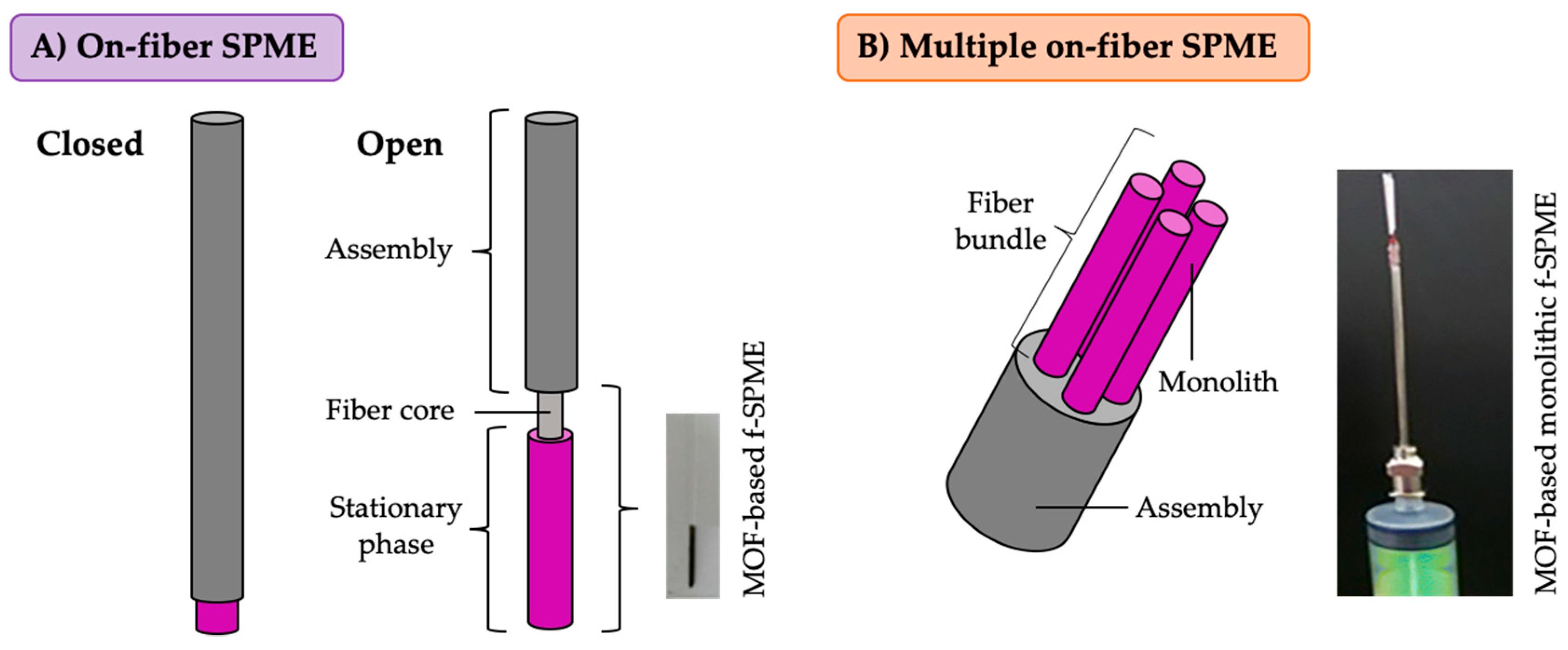
3. MOFs in On-Fiber Solid-Phase Microextraction (f-SPME)

3.1. Overwiev on Commercial f-SPME Devices

In its more common configuration, the SPME device involves a fiber-shaped support coated with the extracting phase leading to the on-fiber SPME (f-SPME), as shown in Figure 4A. This SPME configuration normally performs in two main extraction modes: headspace (HS) SPME, in which the fiber exposes to the headspace over the sample, and direct immersion mode (DI-SPME), where the fiber immerses completely in the aqueous sample. The final desorption step can be accomplished either by placing the fiber in the inlet of a gas chromatography (GC) system (the coating resists high temperatures and the analytes volatilize and get into the GC) or by exposing the fiber to a small amount (<1 mL) of organic solvent (solubilizing analytes while preserving the coating). The thermal desorption approach is the most desirable since it leads to a solvent-free extraction method.
Currently, several brands, including Supelco (Merck) [53] and PAL from CTC Analytics (Restek) [54], supply SPME fibers coated with stationary phases of different polarities and thicknesses. All commercial stationary phases for f-SPME contain a liquid polymer, which is the main component of the coating in the case of absorbent-type fibers (polydimethylsiloxane (PDMS), polyacrylate, and polyethyleneglycol), or is the liquid bulk material in which the solid sorbent is suspended in the case of adsorbent-type stationary fibers (carboxen/PDMS, PDMS/divinylbenzene, and divinylbenzene/carboxen/PDMS).
For the preparation of commercial f-SPME devices, fused silica fibers and metal wires act as the core to support the coating material, with diameters of 100 and 128 µm, respectively [55]. Despite the fragility of fused silica, it is the preferred core for most f-SPME devices since the diameter can be highly controlled and long fibers can be coated precisely with absorbent materials during the manufacturing. Stableflex cores, consisting of fused fibers coated with a thin layer of an inert polymer, and metallic wires, composed of a flexible and thermally stable non-ferrous metal alloy, were introduced to overcome this stability issue [55]. The use of these novel substrates as cores improves the bonding of the adsorbent-type materials during the coating process, which also helps in improving the robustness and reproducibility between batches of the resulting device.
Regarding the size of the f-SPME devices, commercial fibers consists of coated cores of 1 cm. The thicknesses of the coating are up to 100 µm depending on the composition of the sorbent material [53,54]. Despite thicker coatings possibly leading to an improvement on the extraction capability of the SPME fiber, they may also require long extraction times to reach equilibrium when operating [41]. These coated cores assemble in a device that resembles a syringe to facilitate its manipulation and the automation of the methodology. It allows exposing the extracting phase to the sample by pushing the plunger forward, while the fiber experience retraction and protection by pulling the plunger back.
The f-SPME mode is the most widely-exploited approach within all the SPME configurations reported up to date (Figure 2). This success relates to its huge trade expansion in the analysis field [56,57,58], the existence of standard methods proposing this technique [59,60], together with the simplicity of its operation and the easiness in the preparation of these fibers in comparison with other SPME devices.
Despite the commercially available coatings allow the application of this technique for extracting a broad range of compounds, they still lack selectivity and present relatively low thermal stability [41]. In this sense, considering the interesting properties of MOFs, they have been explored as sorbent coatings for f-SPME [32].

3.2. Preparation of MOF-Based f-SPME Devices

Table 1 includes several representative examples of the reported MOF-based coatings for this SPME geometry together with other configurations [48,49,50,51,61,62,63,64,65,66,67,68,69,70,71,72,73,74,75,76]. The vast majority of reported MOF-based f-SPME devices uses the most common MOFs, such as: HKUST-1—composed of copper nodes and 1,3,5-benzenetricarboxylate struts [61,65,77,78,79]; UiO-66—formed by the combination of Zr clusters and 1,4-benzenedicarboxylate ligands [62,67,80,81]; MIL-type MOFs, synthesized using 1,4-benzenedicarboxylate ligands and different metal ions, including Cr [68,69,82,83], Fe [84,85,86,87], and Al [66,88]; and MOFs composed of Zn metal centers, including MOF-5 with 1,4-benzenedicarboxylate as ligand [64,89,90,91,92], and the family of ZIF MOFs containing imidazolate-based ligands [63,70,93,94,95,96]. The selection of these MOFs over others (particularly considering the vast list of possible MOFs) lies on their easy preparation and inter-batch reproducibility of their preparation, together with the fact that their characterization is thorough. To sum up, MOFs containing Zn, Zr, and trivalent metals in their structures normally present higher water and thermal stability [97,98], which makes them adequate candidates for SPME stationary phases.
Given the solid nature of MOFs, different strategies arise for their immobilization on the f-SPME device. The most common approach is the in-situ growth of the MOF on the surface of the substrate used as core [61,62,63,79,84,94,99,100,101,102,103,104]. In this method, the support is immersed in a solution containing the reagents required to synthesize the MOF by the solvothermal method. The surface of the support offers nucleation sites in which the MOF starts growing to form the coating. Among the studies using this coating method, it is worth mentioning the f-SPME based on HKUST-1(Cu) prepared by Sun et al. [79]. In this case, the reaction solution contains the organic ligand and an oxidizing agent since the copper wire used as f-SPME core acts as source of copper ions itself to synthesize the MOF. In other cases, once the MOF attaches to the support (by the in-situ growth), there is an incorporation of additional materials to improve the efficiency of the final coating. Thus, it is interesting to mention the layer-by-layer deposition method of an ionic liquid (IL) and coating with PDMS after the in-situ growth of the MOF IRMOF-3(Zn) reported by Zheng et al. [100]. The PDMS layer helps to protect the coating, while the IL plays an important role on the extraction efficiency of the resulting f-SPME device. The in-situ growth approach has also been reported for the preparation of f-SPME devices coated with composites containing MOFs and carbon-based materials [92,105]. In these cases, the carbon-based material requires dispersion in the reaction solution together with the starting materials for the synthesis of the MOF. In the study reported by Wu et al. [92], an IL is also included in the resulting coating by the functionalization of graphene prior to its addition to the reaction solution. The incorporation of the IL leads to a better bonding between the graphene and the MOF-5(Zn) used for the preparation of the extracting phase, which also improves the uniformity and stability of the f-SPME device.
Other supporting methods base on the electrodeposition of the MOF [64,91]. In this strategy, the working electrode is also the core of the f-SPME device, and cyclic voltammetry ensures that the MOF coats its surface. In the examples reported, the electrodeposition step ensures that triethylamine-modified MOF-5 coats the stainless-steel rod by including triethylamine hydrochloride in the electrolyte solution together with the metal salt and the organic acid used as ligand.
A simpler coating method involves the immersion of the support in a dispersion of the MOF or directly in the MOF powder [93,106], using always the as-synthetized MOF by any of the usual routes (usually the solvothermal method). This procedure needs repetition several times with heating steps between the dipping cycles until reaching the desired thickness. Despite its simplicity, it is hardly used to include neat MOFs in the fibers but to prepare f-SPME devices with hybrid phases composed of MOFs together with carbonaceous materials [65,77,87,90]. For their preparation, the initial powder contains a mixture of the MOF with the carbon-based additive at a specific proportion and the fiber dips in the suspension or powder. MOF-based sorbents benefit from the incorporation of graphene derivatives and carbon nanotubes to improve the extraction performance of the device towards aromatic compounds.
Taking into account that all MOFs (including the abovementioned composites) appear as solid particles in contrast to the high viscous liquid-like polymers used in the preparation of commercial f-SPME devices, the fiber core for MOFs (and MOFs composites) must comply several requirements to avoid detachment of the solid coating from the support [32]. Thus, most reported MOF-based SPME fibers use stainless steel wires as core, with the same diameter as commercial fibers [61,63,64,84,87,90,91,92,93,99,100,102,103,104,106]. To increase the contact area between the core and the solid during the coating process there is a cleaning step of the metallic rod with different solvents and/or treating steps with acid solutions to obtain a rough surface. With the aim of amending the link of the stationary phase to the core while using a robust metallic support, the functionalization of the stainless-steel wires with silanization agents results are also quite interesting [63,87,90]. In this case, a microstructured silver layer on the surface of the wire solves the non-reactive character of the stainless steel.
Fused silica and quartz have also been used for the development of MOF-based coatings for this SPME configuration [62,65,77,94,101,105]. Despite the fragility exhibited by these supports, their composition allows an easy functionalization of the surface with amino or carboxylic groups by dipping the fibers in a solution containing the silanization agent, after pretreating them with acids and bases to expose the silanol groups. This step may ensure a chemical link between the support and the MOF-based extracting phase, and consequently upgrade the stability of the coating, since these groups can react with the organic ligands used for the synthesis of the MOF [32].
As mentioned in Section 3.1, commercial f-SPME devices with solid materials require a liquid polymer to attach the stationary phase to the core. This justifies the use of glues to attach the MOF coatings to the stainless-steel wires in a high number of studies [47,66,67,81,82,85,86,88,89,107,108,109,110,111,112,113], or even to fused silica [68]. The sealant is used in an amount that it does not block the pores of the solid sorbent and it does not participate in the extraction process [32,55]. In general, the support is first dipped in the sealant and then in the MOF powder to obtain the coating. The immersion of the fiber in the glue has also been accomplished as the final step of the coating procedure [82], with the glue acting as a protective layer; or even the glue is previously added to the MOF powder and the fiber is immersed in the mixture to obtain the f-SPME device [109,112]. In some cases, the procedure requires repetitions to control the thickness and obtain thicker coatings. Silicone and epoxy sealants are commonly used, but other adhesives consisting of different polymers have also been proposed, such as polyimide [47,109], polydopamine [86], polyethersulfone [112], and polyacrylonitrile [68].
More sophisticated methods have been described for the preparation of polymeric coatings containing MOFs, such as the sol–gel approach [69,78,83,95,96,114,115]. In these studies, the MOF particles need dispersion in the sol–gel solution, where the stainless-steel support is dipped to obtain the coating after letting it dry at room or high temperatures. This preparation method provides stationary phases that easily bond to the core, also ensuring a homogenous distribution of the MOF through the coating. In the study reported by Bagheri et al. [116], a MOF-polyaniline composite is electro-polymerized on the fiber core by applying a constant potential to the monomer solution, which contains the MOF particles dispersed.
Despite the widely use of f-SPME configurations, the enhancement of the extraction rate to reduce the time to reach the equilibrium in f-SPME applications can be accomplished by using a SPME device composed of multiple fibers, as recently proposed. These fibers have low diameters and are spaced in a way that the gap between the fibers is bigger than the boundary layer formed around the coatings, as shown in Figure 4B [41,117]. Mirzajani et al. reported MOFs in this approach [70]. The SPME device involves a fiber bundle prepared by combining four polymeric monoliths with a diameter of 0.35 cm. The composite consists of a molecularly imprinted polymer doped with graphene oxide and the MOF ZIF-8(Zn), which helps generating a highly selective material due to its pore topology. The use of monoliths yields a highly stable and flexible device that can be easily prepared using molds, which also provide high inter-batch reproducibility.

3.3. Analytical Performance of MOF-Based f-SPME Devices

Most of the MOF-based coatings reported have lengths of 1 cm, while their thicknesses, estimated by obtaining scanning electron microscopy micrographs of the resulting f-SPME device, ranged from 2 µm to 150 µm regardless of the composition of the stationary phase and the coating method. The as-prepared MOFs coatings in f-SPME are commonly incorporated into a 5 µL GC syringe [47,61,62,65,66,67,69,70,77,81,83,84,85,87,88,90,93,94,95,96,101,102,103,104,106,108,114,115], are mounted in a commercial f-SPME assembly [82,89,100,109,112], or into a lab-made device [68,78,116]. The average lifetime of the MOF f-SPME devices is around 100–120 extractions, with the exception of the fiber prepared with the MOF MAF-66 (Zn as metal center and 3-amino-1,2,4-triazole as organic ligand) for which the extraction performance was still the same after 270 extractions [106]. Regarding the inter-fiber precision, which provides information of the reproducibility of the preparation method despite evaluating the fibers for a specific application, it was always lower than 14%, being even lower than 5.2% for the multiple fiber device [70].
As expected, taking into account the characteristics of the SPME technique and the high thermal stability of MOFs, practically all the f-SPME devices combine with GC analysis. The desorption temperatures used are in general close to the maximum temperature at which MOFs keep their crystallinity, thus being always higher than 200 °C, with an average value of 250 °C. The highest desorption temperature reported was 300 °C for the f-SPME coatings prepared with MIL-88B(Fe) [84], MOF-5(Zn) [92], UiO-66(Zr) [81], and HKUST-1(Cu) [79].
MOFs fibers have been evaluated in HS mode in combination with GC for the extraction of an enormous variety of compounds: from PAHs [66,69,79,82,100,102,103,106,108,111], and benzene derivatives [47,82,99,101,110,114,116], to phenols [67,89,92,94]. Water is the most common matrix analyzed, but for example amines have been extracted from urine samples [115] and latex gloves [80], thus proving the validity of MOF f-SPME fibers when dealing with complex samples. MOF f-SPME devices are also useful for the determination of benzene homologues in indoor air [61] and aldehydes in exhaled breath [95].
The DI-SPME-GC methods with these fibers has been used for the analysis of water samples coming from different sources [62,81,85,88,96,104,105,107,109,113], aqueous extracts of foods [85,87,90], and aqueous extracts of soils [62,104,105]. PAHs [62,81,85,96,104,105,107,109] and pesticides [90,107,113] have been the most common analytes determined with the developed methods using the DI mode.
Only four studies reported liquid chromatography (LC) applications with MOFs fibers in the DI mode [68,70,78,107], and using a small amount of an organic solvent in the desorption step [64,68,78], or an aqueous solution at a fixed pH value in the case of the multiple fiber device [70]. It is important to highlight the stability of the triethylamine-modified MOF-5(Zn) coating prepared by electrodeposition [64,91], since it is stable in polar, non-polar, and even halogenated organic solvents, in contrast to commercial coatings, which tend to swell in organic solvents. These DI-SPME-LC methods were intended to the determination of hormones [64,70], and drugs [68,78], in biological and food samples, respectively. It is important to highlight the application of the MIL-101-NH2 f-SPME device (Cr as metal center and 2-amino-1,4-benzenedicarboxylate as ligand, prepared using polyacrylonitrile as adhesive) for in-vivo analysis, exhibiting better results than commercial fibers for the extraction of antibiotics from living fishes [68].

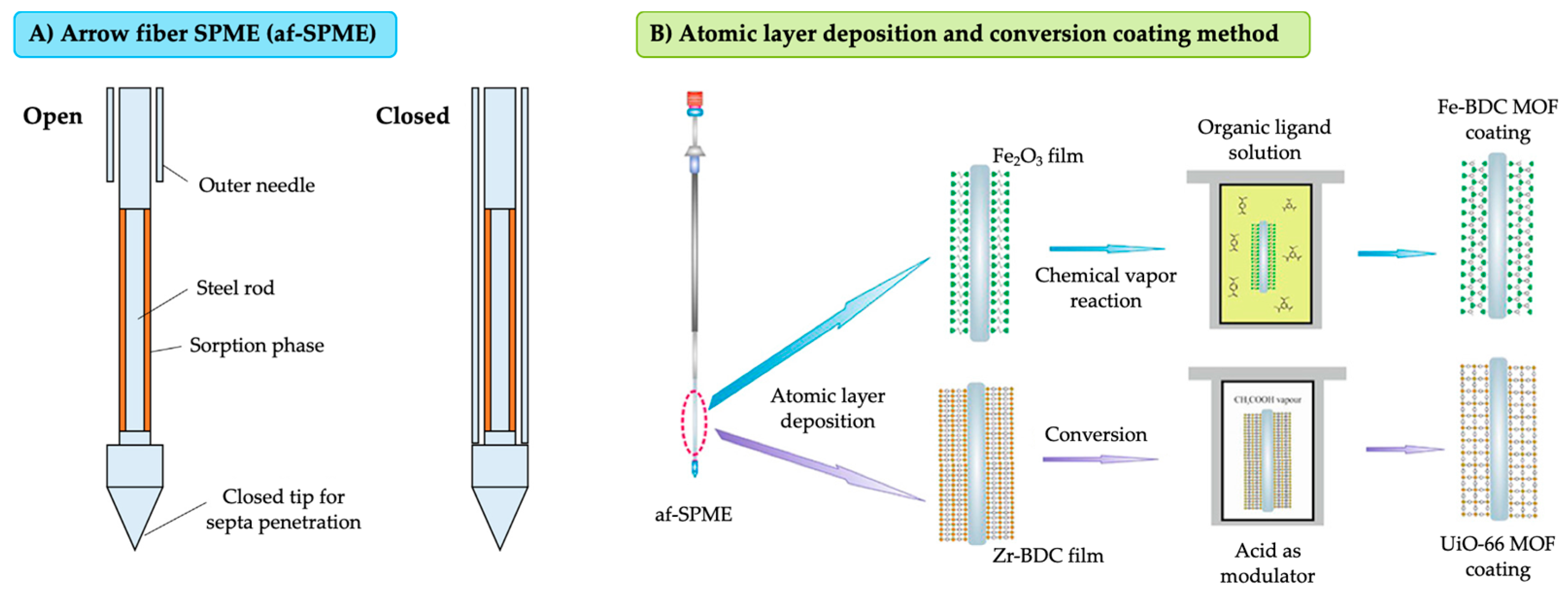
4. MOFs in On-Arrow-Fiber Solid-Phase Microextraction (af-SPME)

SPME arrow fibers (af-SPME) appears as a variation of the f-SPME device to improve the robustness of the design [43]. In this geometry, a large volume of the sorbent (compared to conventional f-SPME devices) coats the sharp closed tip of a steel rod, as shown in Figure 5A. As the amount of extracting phase is quite big in this configuration, higher sensitivity is possible in certain applications, while protecting perfectly the coating from matrix components thanks to its design.
These af-SPME devices are already commercially available, manufactured by CTC Analytics [118]. The available stationary phases are the same as those for f-SPME: polymer-based coatings with different polarities depending on their composition. The length of the coating is 2 cm, the rods have outer diameters of 1.1 or 1.5 mm, and the thicknesses range from 100 µm to 250 µm for the PDMS phase. Despite the novelty of this configuration, MOFs have also been explored as potential sorbent materials for the development of af-SPME devices, which were used in combination with GC analysis [51,119].
The MOFs ZIF-8(Zn) [51] and UiO-66(Zr) [119] in af-SPME have been attached to stainless steel rods using adhesives. In the case of ZIF-8 af-SPME [51], a suspension containing the previously synthesized MOF and polyvinylchloride is prepared, and the fiber support (2 cm) is dipped several times in the mixture and subjected to high temperatures to obtain a thickness of 70 µm. These fibers were tested in the HS extraction of alkylamines from wastewater samples and from aqueous extracts of fish and mushrooms. For the UiO-66-based device [119], the coating method consisted of dipping the arrow fiber first in diluted silicone sealant and then in the suspension of the solid material several times to obtain a thickness of 25 µm. In order to increase the extraction capability of the sorbent towards PAHs, there is a combination of UiO-66 MOF with molybdenum disulfide. The device was evaluated in HS mode and in combination with GC for the analysis of aqueous extracts of fish samples.
Lan et al. [71] proposed a new coating strategy based on atomic layer deposition (ALD) and conversion methods. The entire approach permits the preparation of more selective af-SPME devices coated with different MOFs: the MOF Fe-BDC (composed of Fe metal centers and 1,4-benzenedicarboxylate ligands) was the best for the extraction of benzene-containing polar compounds, while the UiO-66(Zr) coating exhibited better results for polar and aromatic analytes. Figure 5B includes a scheme of the experimental procedure followed in this coating method. In the case of Fe-BDC MOF, ALD permitted the support of Fe2O3 films on the surface of the steel rod. This oxide layer acted then as a source of Fe ions for the synthesis of the MOF. In the conversion step, the af-SPME assembly was immersed in a solution containing the organic ligand to perform a simple vapor–solid reaction, thus obtaining the MOF structure. This method was also used for the preparation of Al-containing MOFs and using similar organic ligands, but the analytical characteristics of the coating were not satisfactory. For the UiO-66 af-SPME, a thin film of the MOF precursor (Zr-BDC) was supported directly on the steel wire instead of an oxide layer. This layer then easily transforms into UiO-66 using the modulator vapor. Despite the small thicknesses obtained for these coatings (~2 and 7.5 µm), comparative and even better results were achieved when extracting polar compounds from wastewaters compared with polymeric commercial coatings.

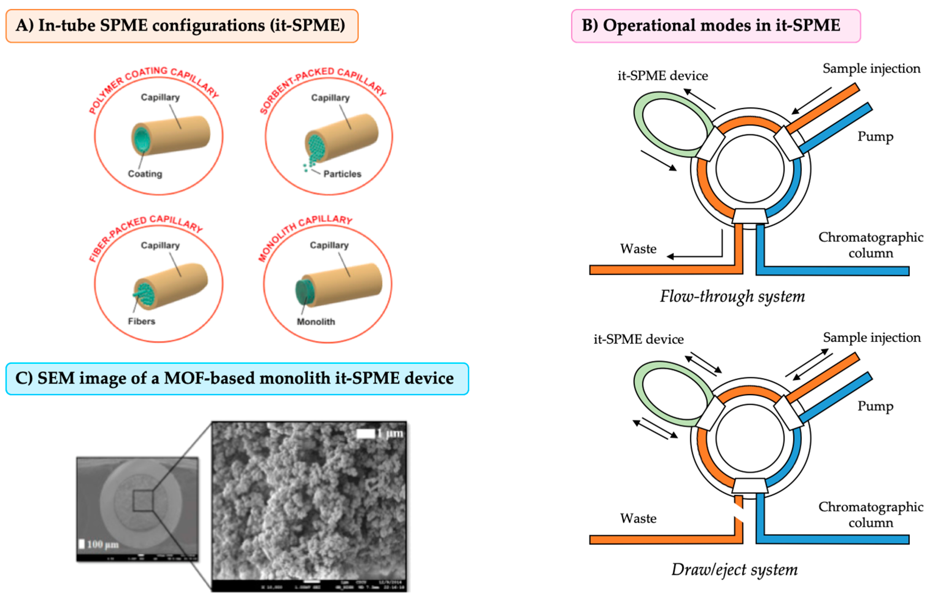
5. MOFs in In-Tube Solid-Phase Microextraction (it-SPME)

The in-tube solid-phase microextraction configuration (it-SPME) was developed practically after the development of the conventional f-SPME, mainly to improve the drawbacks related with the coupling of the technique with LC. Although the high success of f-SPME devices in many analytical applications, the extraction of non-volatile, semi-volatile, and/or thermo-labile compounds (not adequate for GC) was a significant hurdle to overcome.
The introduction of it-SPME devices facilitates the online and direct injection in a LC system, and even more important, its automation [120]. The first it-SPME devices consisted on 60 cm sections of a GC capillary column, with an internal diameter of 0.25 mm and an internal thin film of the stationary phase coating the capillary. Depending on the nature of the stationary phase, the film thickness varies, exhibiting slightly different internal volumes among the devices. Nevertheless, the nature of the film is the main factor responsible of the difference in the behavior [120]. Nowadays, most developed it-SPME devices use open tubular fused-silica capillaries, with a thin film of the extractant material on the inner walls. The development of other capillary modes shifts to the incorporation of novel materials and the improvement of the technique. Other capillary modes include sorbent-packed, fiber-packed, and monolithic phases [44,121,122]. Figure 6A compiles a representation of the main four it-SPME capillary configurations.
There are several operational modes for it-SPME depending on the number of pumps and valves. Nevertheless, they can be divided mainly into two configurations attending to the introduction of the sample: the flow-through system and the draw/eject system. In the first one, the injection of the sample can be performed manually or automated, and the sample is continuously injected into the device following a unique direction way. In the draw/eject mode, it requires an automatic sample introduction system (programmable). The sample is injected, flows through the device, and goes back to the sample vial through the device again completing a cycle. In this modality, it is important not only to optimize the sample flow, but also the number of required cycles to obtain the maximum extraction efficiency [44,122]. Figure 6B shows a schematic representation of both configurations.
Up to date, the use of MOFs as sorbent material in it-SPME is not extended, and only few studies have been reported so far using MIL-101(Cr) [72], MIL-53(Al) [49,123], and ZIF-8(Zn) [124], in all cases for the determination of environmental pollutants in water.
In the cases of MIL-101(Cr) and MIL-53(Al), the devices consist of a glass capillary filled with a monolith composed of a polymer and the MOF. Thus, the glass capillary was cut in sections of 4–10 cm length, followed by washing with concentrated NaOH to activate the silanol groups. Then, the inner walls of the capillary were vinylated to guarantee the attachment of the monolith. [49,72,123]. Afterwards, the mixture suspension containing the necessary amount of MOF (as prepared and already activated), butyl methacrylate as monomer, ethylene dimethacrylate as cross-linker agent, azo-bis-isobutyronitrile as radical initiator, and a porogenic solvent fills the capillary. Once the sides of the capillary are sealed, a microwave-assisted polymerization takes place. It is important to ensure the correct dispersion and homogenization of the mixture suspension before filling the capillary to get a homogenous it-SPME device. Finally, there is a clean-up step to remove the unreacted chemicals from the device [49,72,123]. Figure 6C shows an electronic scanning microscopy image of the MIL-53(Al) monolith-based capillary it-SPME device [123]. One of the most important factors to optimize in this kind of devices is the amount of MOF in the monolith. If large amounts of MOF are used, the monolith structure would be more compact, thus making the diffusion of the sample and solvents difficult (and in turns resulting in a decreasing of the extraction efficiency of the final device) [123].
Regarding the ZIF-8-based it-SPME device proposed by Ling and Chen [124], it consisted of a fiber-packed capillary. In this case, the incorporation of the MOF requires an electrodeposition step followed by an in-situ crystal growth. The general procedure starts by using a strong acid and a base in order to activate the surface of carbon fibers (bundle of 13 cm). Then, the electrodeposition of ZnO takes places by immersing the carbon fibers (as the working electrode on a three-electrodes system) in a solution of zinc nitrate. The deposition of the oxide takes places by cyclic voltammetry. Once the ZnO is formed all over the surface of the fibers, the cyclic voltammetry is stopped, and the fibers bundle is washed and heated at 100 °C to ensure the immobilization of the oxide. This strategy renders supported ZnO crystals of 30–80 nm. Consecutively, the solvothermal synthesis ensures the growth of the MOF ZIF-8 by immersing the ZnO-based carbon fibers bundle into a solution of the organic linker under adequate growing conditions, followed by packing it in a polyetheretherketone (PEEK) tube. The analytical applications involved the determination of Sudan dyes in environmental waters [124].

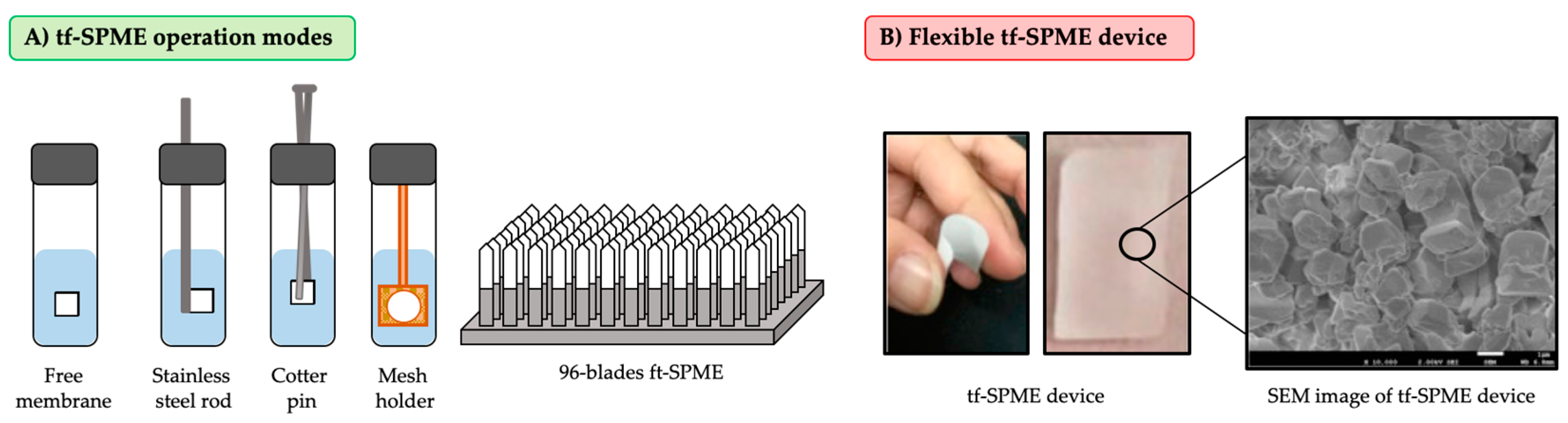
6. MOFs in Thin-Film Solid-Phase Microextraction (tf-SPME)

While it is clear that the enlargement of the thickness of the sorbent material in f-SPME devices implies an increase on the amount of extracted analyte, it also comes with long extraction times to reach the equilibrium due to the radial diffusion of the analytes [41]. Thin film solid-phase microextraction (tf-SPME) appears as a solution to increase the sensitivity (using larger sorbent amounts) without increasing the extraction time. Wilcockson and Gobas were the first to propose the tf-SPME configuration [125]. This first device consisted of a glass coverslip coated with a 0.33 µm thin film of ethylene vinyl acetate (acting as sorbent coating). The device was tested in the analysis of toxic organic chemicals in aqueous extracts of fish samples.
In tf-SPME, the sorbent material covers the surface of a flat material or forms a free membrane with a reduced thickness, with the increasing amount of sorbent being related to the extension of the surface, thus maintaining a high surface area to volume ratio. In this mode, higher sensitivities can be reached given the increased amount of sorbent but requiring shorter times (similar to those of f-SPME) because there are no extra difficulties in diffusion (same as those in f-SPME) [126,127].
The main challenge for the different sampling formats of tf-SPME is to avoid film folding. Among formats, it is possible to cite free-membrane, stainless steel rods, cotter pin, and mess holder configurations. Furthermore, it is possible to automate this extraction technique using 96-blades, which is a variety of the commercial 96-well plates system [128]. Figure 7A shows the main tf-SPME devices configurations.
It is possible to distinguish two different kind of tf-SPME devices attending to their thermal stability: thermostable and non-thermostable films. Thermostable films can be coupled to a temperature desorption unit and directly injected in the GC. As disadvantage, there is a limited number of thermostable films reported in the literature and most of them are the same as the polymeric coatings used in conventional f-SPME. Regarding thermo-labile films, they are used in solvent-assisted desorption applications (implying longer sample preparation times due to the slower diffusion of the analytes in the liquid phase). In addition, the increased size of the device requires the use of higher amounts of eluent solvent (in turn requiring a final step of solvent removal and reconstitution) [45].
The tf-SPME modality recently benefited from the introduction of MOFs. The preparation of MOF-based tf-SPME is easier than other SPME configurations because the increased surface facilitates the MOF growing.
MOFs reported in tf-SPME devices include MIL-53(Al) [50] and ZIF-67(Co) [129]. Other MOFs studied as sorbent material in tf-SPME are UiO-66(Zr), MIL-53(Fe), MIL-100(Fe), MIL-101(Cr), and ZIF-8(Zn) but presented worse analytical performance when compared with the abovementioned MOFs [50]. There are other thin films incorporating MOFs reported in the literature, but they are used as sorbent material in µ-SPE applications instead of tf-SPME strictly [130,131,132,133]. Figure 7B shows an example of a MOF-based tf-SPME device.
In the case of MIL-53(Al), it is incorporated in the thin-films by embedding the MOF (previously synthetized) in a polymer. This method involves the dispersion of the MOF in a volatile solvent (i.e., acetone), and addition of such suspension to a polyvinylidene difluoride (PVDF) solution in dimethylformamide under sonication to ensure homogeneity. Then, the volatile solvent is evaporated, and a dense ink is obtained [50]. The bar coating technique forms the thin film by spreading the ink over a surface. It requires an applicator with an adjustable gap to control the thickness of the film [45], followed by the aging of the film and solvent removal to ensure solidification of the film. The final shape of the tf-SPME device can be easily modulated by proper cutting of the solid membrane obtained. These composites combine the flexibility of the polymers and the high porosity offered by MOFs. The amount of MOF powder cannot be extremely high into the film because it becomes more fragile and flakier. The highest charge reported for a MOF into a membrane for tf-SPME application is 67% (w/w) [50].
Recently, Mohammadi et al. have proposed a method that combines electrospinning and the in-situ solvothermal growth to prepare a ZIF-67(Co)-based tf-SPME device [129]. The electrospinning implies forming a composite of polyacrylonitrile and Co3O4 nanofibers. By heating, the polyacrylonitrile suffers calcination and the polymer is removed from the film structure. Afterwards, this film gets in contact with the organic linker required for the preparation of the ZIF-67(Co) (2-methylimidazole) at adequate conditions to ensure formation of the nanofibers. The main advantage of this method is that the MOF is self-supported without the use of a mesh or a polymer, but still being a flexible membrane.
Regarding the applicability of the MOF-based tf-SPME devices, just the self-supported ZIF-67(Co) film permitted a thermal desorption. In this last case, the application was the determination of pesticides [129]. In terms of analytical performance, they present adequate intra- and inter-device precision, with reported relative standard deviation values lower than 11.4%. Samples analyzed include water [129] and biological fluids [50], for the determination of estrogens [50] and pesticides [129]. Table 1 recaps a representative study of tf-SPME using MOFs as sorbents.

7. MOFs in Stir-Bar (sb-SPME) and Stir-Cake Solid-Phase Microextraction (sc-SPME)

Baltussen et al. introduced the stir-bar solid-phase microextraction (sb-SPME) configuration as an alternative to conventional f-SPME, particularly useful for compounds with low octanol/water partitioning coefficient (non-polar compounds) [134]. The device consisted of a magnetic stir bar coated with PDMS. The sample is stirred with the bar at an adequate agitation rate. The bar is removed after proper extraction time, and a direct thermal desorption step takes place in a specific GC injection port called thermal desorption unit. In this configuration, part of the sorbent is in contact with the bottom of the sample container thus blocking possible interactions between the analytes and a portion of the extractant material. Stir-cake solid-phase microextraction (sc-SPME) emerged as a solution to this problem. The sorbent (in general a monolith) is located in a cylindrical device avoiding the contact between the sorbent and the bottom of the vessels thus improving the entire extraction efficiency [135,136].
Both configurations follow the same extraction fundamentals as conventional SPME. However, the amount of the sorbent material in both modes sb-SPME and sc-SPME are ~50–200 times bigger than the amount used in conventional f-SPME, thus permitting increasing the extraction capacity towards target analytes [137], but also increasing the extraction time.
Currently, there are only two commercially available sb-SPME devices distributed by Gerstel: one coated with PDMS and the other with a PDMS/ethylene glycol copolymer [138]. Although these coatings possess many merits such as high sensitivity and good reproducibility, they also have low selectivity and require long extraction times to reach the equilibrium conditions. In addition, recoveries for polar compounds are poor due to the non-polar nature of the sorbent, being necessary a derivatization step for their extraction. Given these drawbacks, recent developments of sb-SPME devices focus on the development of more selective coatings with faster extraction kinetics, with MOFs not being an exception [46].
MOFs used as sorbents in sb-SPME include IRMOF-3(Zn) [73], MIL-53(Al)-NH2 [74], MOF-5(Zn and Fe) [75,139], ZIF-8 [140], MIL-101(Cr) and its amino functionalized version [48,141], MIL-68(Al) [142], ZIF-67(Co) [143], and UiO-66-NH2 [76].
The main procedure followed to incorporate MOFs in sb-SPME devices is the sol–gel approach. The devices prepared by this procedure have three components: an iron wire or metallic rod of ~1–3 cm length, a glass jacket, and the sorbent. The iron wire or metallic rod is the responsible of the agitation under the magnetic field while the glass jacket isolates the metallic wire form the water sample, avoiding its corrosion. The glass jacket also offers a homogeneous tunable surface for the immobilization of the coating when immersing the bar into the sol–gel solution containing the MOF dispersed into a polymeric solution. Then, the device is removed from the sol–gel solution and the self-assembly of the coating finishes by heating [48,73,74].
An alternative to sol–gel is the synthesis of monoliths by polymerization. The general procedure implies filling a template with a pre-polymeric solution (containing the MOF powder dispersed or its precursors), polymerization, removal of the template, and a final wash to clean the monolith [76,140,141]. Thus, the shape and dimension of the devices depends on the template and not on the support. Even the use a support is not required if magnetic nanoparticles are dispersed in the pre-polymeric suspension [76]. Recently, Du et al. took advantage of this strategy for the preparation of the first MOF-based sc-SPME device by dispersing Fe3O4@HKUST-1 core–shell particles in a pre-polymeric solution of 2-ethylhexylacrylate/divinylbenzene/methyl methacrylate [52]. Although the MOF composite monolith does not utilize a classical sc-SPME support, its visual geometry and shape resembles that of the classical sc-SPME device.
Another option is the in-situ solvothermal growth of the crystals onto other type of supports. Hu et al. used this strategy with a porous copper foam as support. The foam immersed in the solution containing the precursors of MOF-5(Zn) and, after impregnation, the support and the solution are set on the Teflon-lined autoclave, which is heated to form the MOF [139]. In this case, the sb-SPME device is used in the HS mode and using a lab-made rotor to stir the device. As the direct growth of crystals over the support surface is not easy in terms of ensuring homogeneity, a similar approach to ALD strategy has been used, promoting the crystal growth out of the metal nanoparticles previously electrodeposited all over the surface of the support [143]. The main disadvantage of these devices is the weak union MOF-support. The friction between the stir bar and the sample container causes a progressive loose of the MOFs, thus reducing the lifetime of the device. Wang et al. developed the use of a dumbbell-shaped PEEK jacket to improve the mechanical strength. However, PEEK material is a highly inert material, requiring several aggressive pretreatment steps to obtain an activate surface before the in-situ growth [142].
Paradoxically, although the main attractive property of MOFs in this configuration is their thermal stability to perform direct thermal desorption, most of the studies published used a solvent desorption followed by LC [73,74,76,141,142,143].

8. Comparison with Other MOF-Based Extraction Methods

The number of studies that report the use of MOFs as extraction sorbents in µ-dSPE, m-µ-dSPE, and SPME (in all their variations), is similar. The reason behind the selection of any of these solid-phase strategies over others relies on the specific requirements for a certain application. Therefore, it is difficult to compare the analytical performance and features of the different solid-based extraction methods using MOFs from a generic point of view.
Trying to establish certain parallelism, specific analytical applications have been targeted with the intended comparison purpose. Thus, Table 2 includes some operational characteristics and analytical parameters of different solid-based extraction methods using MOFs for two representative applications: the determination of pesticides (including organochlorine and organophosphorus pesticides) and drugs (covering antibiotics and anti-inflammatory drugs) in waters [48,65,72,78,129,141,144,145,146,147]. These specific applications were selected for being those most commonly reported in the literature using the different SPME devices discussed in the present review article. It is important to highlight that the MOF used in each study is different (with MIL-101(Cr) and HKUST-1 the most used) and, therefore, the comparison of analytical performance must be taken into account only in a qualitative manner. In the same manner, the limit of detection (LOD) is not a reliable parameter to compare the proposed methods due to the variety of detection systems used in the selected applications, which present different selectivity and sensitivity towards the target analytes (not the same MS versus UV in terms of LOD). To sum up, LODs are not always calculated in the same manner by the different authors.
In any case, an important (if not main) advantage of the SPME approach over the remaining solid-based extraction methods lies in the extremely low amount of MOF used for the preparation of the SPME devices, which also provides impressive enrichment factors. MOFs amounts between 0.5 [145] and 40 mg [144,146] have been reported for µ-SPE, µ-dSPE, and m-µ-dSPE methods, while in the case of SPME, depending on the size of the device (length and thickness of the coatings), the maximum volume of sorbent used is around 2 µL. As for the volume of sample required, small volumes (10 mL as average) are required in all cases except for µ-SPE, for which a volume of 60 mL of water sample is needed to reach low LODs for the determination of drugs in waters, and this is despite the use of LC-MS/MS [146].
Regarding the operational features of each extraction method, it is worth mentioning the simplicity of the SPME approaches. The extraction procedure in these cases is accomplished in two steps: the extraction and the desorption. µ-SPE, µ-dSPE, and m-µ-dSPE strategies require more tedious and laborious steps during the process, such as washings, decantation, or centrifugation and filtration. Moreover, practically in all of the studies using non-SPME strategies, the desorption of the analytes from the MOF is accomplished using a solvent, which is then evaporated followed by reconstitution to ensure preconcentration and compatibility with the analytical system. The increasing number of steps is a potential source of errors, and the use of organic solvents is still required in the analysis, leading to environmental issues. SPME devices easily couple to GC systems (thermal desorption), thus permitting the development of greener methods [65,129].
As it can be also observed in Table 2, the extraction methods dealing with SPME devices require longer extraction times to reach similar results than those obtained with the other approaches. However, as it was mentioned before, the SPME extraction process involves only two steps, which is still simpler than µ-SPE or µ-dSPE methods despite their possibly being faster. Given this simplicity, the automation of SPME regardless of the configuration of the device has been already reported for many applications. In any case, the greatest appeal of SPME is the reusability of the extraction device, which is never recommended for µ-SPE [146] and has been barely proven for µ-dSPE applications [144]. All these facts contribute to reduce the costs of the analysis per sample in the case of SPME.
In summary, SPME (in all configurations) with MOF-based coatings is a promising alternative among reported solid-based extraction methods for routine analysis given the following advantages: high enrichment factors, the possibility of tuning the MOF for a certain application, the reduced number of steps in the process, and the possibility of reusing the device (up to more than 100 times in some cases) together with the ease of automation for the entire procedure (from the introduction of the device in the sample to the desorption or injection in the analytical system).

9. Concluding Remarks

The success of SPME methods within analytical laboratories is evident nowadays, given advantages such as the simplicity of its operation and the high sensitivity and preconcentration achieved due to the design of the different SPME devices. Considering the outstanding properties of MOFs—such as synthetic tunability, versatility, high chemical and thermal stability of MOFs, and impressive surface area—together with the advances on the different synthetic and deposition routes to prepare MOFs and MOF-coated surfaces, the increasing number of applications of MOFs in the SPME field is not surprising. Indeed, we foresee a rise in their applicability in a variety of SPME devices in the years to come. In any case, more efforts are still required within the MOFs-analytical community to have MOFs as any common extraction sorbent in analytical chemistry laboratories. Among them: scalable processes to ensure the production of high amounts of MOFs, the need of increasing research on green MOFs and greener ways to prepare MOFs, together with increasing studies with comparison of performance with other sorbents and with conventional (micro) extraction methods.

Funding

This research was funded by the Spanish Ministry of Economy, Industry and Competitiveness grant number MAT2017-89207-R.

Acknowledgments

A.G.-S. and I.P.-F. thank Agencia Canaria de Investigación, Innovación y Sociedad de la Información (ACIISI), co-funded by the European Social Fund, for their FPI PhD fellowships. J.P. thanks the “Agustín de Betancourt” Canary Program for his research associate position at ULL.

Conflicts of Interest

The authors declare no conflict of interest.

Abbreviations

af-SPMEarrow fiber solid-phase microextraction
ALDatomic layer deposition
BMA-EDMAbutyl methacrylate-ethylene dimethacrylate
CEcapillary electrophoresis
CECcapillary electrochromatography
d-µ-SPEdispersive solid-phase microextraction
DADdiode array detection
DIdirect immersion
ECDelectron capture detection
f-SPMEon-fiber solid-phase microextraction
FIDflame ionization detection
GCgas chromatography
FPDflame photometric detection
HSheadspace
ILionic liquid
IRMOFisoreticular metal–organic framework
it-SPMEin-tube solid-phase microextraction
LCliquid chromatography
LODlimit of detection
m-d-µ-SPEmagnetic-assisted miniaturized solid-phase extraction
MIPmolecularly imprinted polymer
MNPmagnetic nanoparticle
MOFmetal–organic framework
MSmass spectrometry
MS/MStandem mass spectrometry
OCPorganochlorine pesticide
OPPorganophosphorus pesticide
PAHpolycyclic aromatic hydrocarbon
PANpolyacrylonitrile
PCBpolychlorinated biphenyl
PDMSpolydimethylsiloxane
PEEKpolyetheretherketone
PSpolystyrene
PVCpolyvinylchloride
PVDFpolyvinylidene difluoride
sb-SPMEstir-bar solid-phase microextraction
SBUsecondary building unit
sc-SPMEstir-cake solid-phase microextraction
SESIsecondary electrospray ionization
SPMEsolid-phase microextraction
tf-SPMEthin-film solid-phase microextraction
µ-SPEminiaturized solid-phase extraction

References

  1. Rowsell, J.L.C.; Yaghi, O.M. Metal-Organic Frameworks: A New Class of Porous Materials. Microporous Mesoporous Mater. 2004, 73, 3–14. [Google Scholar] [CrossRef]
  2. Schneemann, A.; Bon, V.; Schwedler, I.; Senkovska, I.; Kaskel, S.; Fischer, R.A. Flexible Metal-Organic Frameworks. Chem. Soc. Rev. 2014, 43, 6062–6096. [Google Scholar] [CrossRef] [PubMed]
  3. Safaei, M.; Foroughi, M.M.; Ebrahimpoor, N.; Jahani, S.; Omidi, A.; Khatami, M. A Review on Metal-Organic Frameworks: Synthesis and Applications. Trends Anal. Chem. 2019, 118, 401–425. [Google Scholar] [CrossRef]
  4. Kalmutzki, M.J.; Hanikel, N.; Yaghi, O.M. Secondary Building Units as the Turning Point in the Development of the Reticular Chemistry of MOFs. Sci. Adv. 2018, 4, 1–16. [Google Scholar] [CrossRef] [PubMed]
  5. Yaghi, O.M. Reticular Chemistry—Construction, Properties, and Precision Reactions of Frameworks. J. Am. Chem. Soc. 2016, 138, 15507–15509. [Google Scholar] [CrossRef]
  6. Eddaoudi, M.; Kim, J.; Rosi, N.; Vodak, D.; Wachter, J.; O’Keeffe, M.; Yaghi, O.M. Systematic Design of Pore Size and Functionality in Isoreticular MOFs and Their Application in Methane Storage. Science 2002, 295, 469–472. [Google Scholar] [CrossRef] [Green Version]
  7. The Cambridge Crystallographic Data Center (CCDC). Available online: https://www.ccdc.cam.ac.uk/ (accessed on 25 July 2019).
  8. Millange, F.; Serre, C. Synthesis, Structure Determination and Properties of MIL-53as and MIL-53ht: The First CrIII Hybrid Inorganic—Organic Microporous Solids: CrIII(OH)·{O2C–C6H4–CO2}·{HO2C–C6H4–CO2H}x. Chem. Commun. 2002, 8, 822–823. [Google Scholar] [CrossRef]
  9. Chui, S.S.Y.; Lo, S.M.F.; Charmant, J.P.H.; Orpen, A.G.; Williams, I.D. A Chemically Functionalizable Nanoporous Material [Cu3(TMA)2 (H2O)3](N). Science 1999, 283, 1148–1150. [Google Scholar] [CrossRef]
  10. Akporiayer, D.E.; Fjellvag, H.; Halvorsen, E.N.; Hustveit, J.; Karlsson, A.; Lillerud, K.P. The synthesis and structure solution of UiO-7, a new molecular sieve. Chem. Commun. 1996, 5, 601–602. [Google Scholar] [CrossRef]
  11. Rocío-Bautista, P.; Pino, V.; Ayala, J.H.; Ruiz-Pérez, C.; Vallcorba, O.; Afonso, A.M.; Pasán, J. A Green Metal-Organic Framework to Monitor Water Contaminants. RSC Adv. 2018, 8, 31304–31310. [Google Scholar] [CrossRef]
  12. Küsgens, P.; Rose, M.; Senkovska, I.; Fröde, H.; Henschel, A.; Siegle, S.; Kaskel, S. Characterization of Metal-Organic Frameworks by Water Adsorption. Microporous Mesoporous Mater. 2009, 120, 325–330. [Google Scholar] [CrossRef]
  13. Tian, Y.; Cai, C.; Ji, Y.; You, X.; Peng, S.; Lee, G. [Co5(im)10·2MB]: A Metal-Organic Open.Framework with Zeolite-Like Topology. Angew. Chem. 2002, 114, 1442–1444. [Google Scholar] [CrossRef]
  14. Feng, D.; Gu, Z.Y.; Li, J.R.; Jiang, H.L.; Wei, Z.; Zhou, H.C. Zirconium-Metalloporphyrin PCN-222: Mesoporous Metal-Organic Frameworks with Ultrahigh Stability as Biomimetic Catalysts. Angew. Chem. Int. Ed. 2012, 51, 10307–10310. [Google Scholar] [CrossRef] [PubMed]
  15. Julien, P.A.; Mottillo, C.; Friščić, T. Metal-Organic Frameworks Meet Scalable and Sustainable Synthesis. Green Chem. 2017, 19, 2729–2747. [Google Scholar] [CrossRef]
  16. Ding, L.; Yazaydin, A.O. Hydrogen and Methane Storage in Ultrahigh Surface Area Metal-Organic Frameworks. Microporous Mesoporous Mater. 2013, 182, 185–190. [Google Scholar] [CrossRef]
  17. Hönicke, I.M.; Senkovska, I.; Bon, V.; Baburin, I.A.; Bönisch, N.; Raschke, S.; Evans, J.D.; Kaskel, S. Balancing Mechanical Stability and Ultrahigh Porosity in Crystalline Framework Materials. Angew. Chem. Int. Ed. 2018, 57, 13780–13783. [Google Scholar] [CrossRef]
  18. Howarth, A.J.; Peters, A.W.; Vermeulen, N.A.; Wang, T.C.; Hupp, J.T.; Farha, O.K. Best Practices for the Synthesis, Activation, and Characterization of Metal−organic Frameworks. Chem. Mater. 2017, 29, 26–39. [Google Scholar] [CrossRef]
  19. Xue, D.X.; Wang, Q.; Bai, J. Amide-Functionalized Metal–Organic Frameworks: Syntheses, Structures and Improved Gas Storage and Separation Properties. Coord. Chem. Rev. 2019, 378, 2–16. [Google Scholar] [CrossRef]
  20. Xu, C.; Fang, R.; Luque, R.; Chen, L.; Li, Y. Functional Metal–Organic Frameworks for Catalytic Applications. Coord. Chem. Rev. 2019, 388, 268–292. [Google Scholar] [CrossRef]
  21. Anik, Ü.; Timur, S.; Dursun, Z. Metal Organic Frameworks in Electrochemical and Optical Sensing Platforms: A Review. Microchim. Acta 2019, 186, 18–24. [Google Scholar] [CrossRef]
  22. He, L.; Liu, Y.; Lau, J.; Fan, W.; Li, Q.; Zhang, C.; Huang, P.; Chen, X. Recent Progress in Nanoscale Metal-Organic Frameworks for Drug Release and Cancer Therapy. Nanomedicine 2019, 14, 1343–1365. [Google Scholar] [CrossRef] [PubMed]
  23. Mehtab, T.; Yasin, G.; Arif, M.; Shakeel, M.; Korai, R.M.; Nadeem, M.; Muhammad, N.; Lu, X. Metal-Organic Frameworks for Energy Storage Devices: Batteries and Supercapacitors. J. Energy Storage 2019, 21, 632–646. [Google Scholar] [CrossRef]
  24. Rocío-Bautista, P.; Termopoli, V. Metal–Organic Frameworks in Solid-Phase Extraction Procedures for Environmental and Food Analyses. Chromatographia 2019, 82, 1191–1205. [Google Scholar] [CrossRef]
  25. Rocío-Bautista, P.; González-Hernández, P.; Pino, V.; Pasán, J.; Afonso, A.M. Metal-Organic Frameworks as Novel Sorbents in Dispersive-Based Microextraction Approaches. Trends Anal. Chem. 2017, 90, 114–134. [Google Scholar] [CrossRef]
  26. González-Hernández, P.; Gutiérrez-Serpa, A.; Rocío-Bautista, P.; Pasán, J.; Ayala, J.H.; Pino, V. Micro-solid Phase Extraction using MOFs. In Metal Organic Frameworks; Mittal, V., Ed.; Central West Publishing: Orange, Australia, 2019; pp. 99–136. [Google Scholar]
  27. Pacheco-Fernández, I.; González-Hernández, P.; Pasán, J.; Ayala, J.H.; Pino, V. The Rise of Metal–Organic Frameworks in Analytical Chemistry. In Handbook of Smart Materials in Analytical Chemistry; De la Guardia, M., Esteve-Turrillas, F.A., Eds.; John Wiley & Sons Inc.: Hoboken, NJ, USA, 2019; pp. 463–502. [Google Scholar]
  28. Maya, F.; Palomino Cabello, C.; Figuerola, A.; Turnes Palomino, G.; Cerdà, V. (Eds.) Immobilization of Metal–Organic Frameworks on Supports for Sample Preparation and Chromatographic Separation. Chromatographia 2019, 82, 361–375. [Google Scholar]
  29. Liang, Y.; Zhang, L.; Zhang, Y. Well-Defined Materials for Chromatographic Separation. Annu. Rev. Anal. Chem. 2019, 12, 451–473. [Google Scholar] [CrossRef]
  30. Faraji, M.; Yamini, Y.; Gholami, M. Recent Advances and Trends in Applications of Solid-Phase Extraction Techniques in Food and Environmental Analysis. Chromatographia 2019, 82, 1207–1249. [Google Scholar] [CrossRef]
  31. Maya, F.; Palomino Cabello, C.; Frizzarin, R.M.; Estela, J.M.; Turnes Palomino, G.; Cerdà, V. Magnetic Solid-Phase Extraction Using Metal-Organic Frameworks (MOFs) and Their Derived Carbons. Trends Anal. Chem. 2017, 90, 142–152. [Google Scholar] [CrossRef]
  32. Rocío-Bautista, P.; Pacheco-Fernández, I.; Pasán, J.; Pino, V. Are Metal-Organic Frameworks Able to Provide a New Generation of Solid-Phase Microextraction Coatings?—A Review. Anal. Chim. Acta 2016, 939, 26–41. [Google Scholar] [CrossRef]
  33. Li, X.; Ma, W.; Li, H.; Bai, Y.; Liu, H. Metal-Organic Frameworks as Advanced Sorbents in Sample Preparation for Small Organic Analytes. Coord. Chem. Rev. 2019, 397, 1–13. [Google Scholar] [CrossRef]
  34. Rocío-Bautista, P.; Taima-Mancera, I.; Pasán, J.; Pino, V. Metal-Organic Frameworks in Green Analytical Chemistry. Separations 2019, 6, 33. [Google Scholar] [CrossRef]
  35. Zhou, Y.Y.; Yan, X.P.; Kim, K.N.; Wang, S.W.; Liu, M.G. Exploration of Coordination Polymer as Sorbent for Flow Injection Solid-Phase Extraction on-Line Coupled with High-Performance Liquid Chromatography for Determination of Polycyclic Aromatic Hydrocarbons in Environmental Materials. J. Chromatogr. A 2006, 1116, 172–178. [Google Scholar] [CrossRef] [PubMed]
  36. Yang, X.Q.; Yang, C.X.; Yan, X.P. Zeolite Imidazolate Framework-8 as Sorbent for on-Line Solid-Phase Extraction Coupled with High-Performance Liquid Chromatography for the Determination of Tetracyclines in Water and Milk Samples. J. Chromatogr. A 2013, 1304, 28–33. [Google Scholar] [CrossRef] [PubMed]
  37. Yang, S.; Chen, C.; Yan, Z.; Cai, Q.; Yao, S. Evaluation of metal-organic framework 5 as a new SPE material for the determination of polycyclic aromatic hydrocarbons in environmental waters. J. Sep. Sci. 2013, 36, 1283–1290. [Google Scholar] [CrossRef]
  38. Ge, D.; Lee, H.K. Sonication-Assisted Emulsification Microextraction Combined with Vortex-Assisted Porous Membrane-Protected Micro-Solid-Phase Extraction Using Mixed Zeolitic Imidazolate Frameworks 8 as Sorbent. J. Chromatogr. A 2012, 1263, 1–6. [Google Scholar] [CrossRef]
  39. Hashemi, B.; Zohrabi, P.; Raza, N.; Kim, K.H. Metal-Organic Frameworks as Advanced Sorbents for the Extraction and Determination of Pollutants from Environmental, Biological, and Food Media. Trends Anal. Chem. 2017, 97, 65–82. [Google Scholar] [CrossRef]
  40. Arthur, C.L.; Pawliszyn, J. Solid Phase Microextraction with Thermal Desorption Using Fused Silica Optical Fibers. Anal. Chem. 1990, 62, 2145–2148. [Google Scholar] [CrossRef]
  41. Piri-Moghadam, H.; Alam, M.N.; Pawliszyn, J. Review of Geometries and Coating Materials in Solid Phase Microextraction: Opportunities, Limitations, and Future Perspectives. Anal. Chim. Acta 2017, 984, 42–65. [Google Scholar] [CrossRef]
  42. Lashgari, M.; Yamini, Y. An Overview of the Most Common Lab-Made Coating Materials in Solid Phase Microextraction. Talanta 2019, 191, 283–306. [Google Scholar] [CrossRef]
  43. Helin, A.; Rönkkö, T.; Parshintsev, J.; Hartonen, K.; Schilling, B.; Läubli, T.; Riekkola, M.L. Solid Phase Microextraction Arrow for the Sampling of Volatile Amines in Wastewater and Atmosphere. J. Chromatogr. A 2015, 1426, 56–63. [Google Scholar] [CrossRef]
  44. Costa Queiroz, M.E.; Donizeti de Souza, I.; Marchioni, C. Current Advances and Applications of In-Tube Solid-Phase Microextraction. Trends Anal. Chem. 2019, 111, 261–278. [Google Scholar] [CrossRef]
  45. Olcer, Y.A.; Tascon, M.; Eroglu, A.E.; Boyacı, E. Thin Film Microextraction: Towards Faster and More Sensitive Microextraction. Trends Anal. Chem. 2019, 113, 93–101. [Google Scholar] [CrossRef]
  46. David, F.; Ochiai, N.; Sandra, P. Two Decades of Stir Bar Sorptive Extraction: A Retrospective and Future Outlook. Trends Anal. Chem. 2019, 112, 102–111. [Google Scholar] [CrossRef]
  47. Niu, J.; Li, Z.; Yang, H.; Ye, C.; Chen, C.; Li, D.; Xu, J.; Fan, L. A Water Resistant Solid-Phase Microextraction Fiber with High Selectivity Prepared by a Metal Organic Framework with Perfluorinated Pores. J. Chromatogr. A 2016, 1441, 16–23. [Google Scholar] [CrossRef]
  48. Xiao, Z.; He, M.; Chen, B.; Hu, B. Polydimethylsiloxane/Metal-Organic Frameworks Coated Stir Bar Sorptive Extraction Coupled to Gas Chromatography-Flame Photometric Detection for the Determination of Organophosphorus Pesticides in Environmental Water Samples. Talanta 2016, 156–157, 126–133. [Google Scholar] [CrossRef]
  49. Shih, Y.H.; Wang, K.Y.; Singco, B.; Lin, C.H.; Huang, H.Y. Metal-Organic Framework-Polymer Composite as a Highly Efficient Sorbent for Sulfonamide Adsorption and Desorption: Effect of Coordinatively Unsaturated Metal Site and Topology. Langmuir 2016, 32, 11465–11473. [Google Scholar] [CrossRef]
  50. Gao, G.; Li, S.; Li, S.; Zhao, L.; Wang, T.; Hou, X. Development and application of vortex-assisted membrane extraction based on metal-organic framework mixed-matrix membrane for the analysis of estrogens in human urine. Anal. Chim. Acta 2018, 1023, 35–43. [Google Scholar] [CrossRef]
  51. Lan, H.; Rönkkö, T.; Parshintsev, J.; Hartonen, K.; Gan, N.; Sakeye, M.; Sarfraz, J.; Riekkola, M.L. Modified Zeolitic Imidazolate Framework-8 as Solid-Phase Microextraction Arrow Coating for Sampling of Amines in Wastewater and Food Samples Followed by Gas Chromatography-Mass Spectrometry. J. Chromatogr. A 2017, 1486, 76–85. [Google Scholar] [CrossRef]
  52. Du, F.; Sun, L.; Tan, W.; Wei, Z.; Nie, H.; Huang, Z.; Ruan, G.; Li, J. Magnetic Stir Cake Sorptive Extraction of Trace Tetracycline Antibiotics in Food Samples: Preparation of Metal–Organic Framework-Embedded PolyHIPE Monolithic Composites, Validation and Application. Anal. Bioanal. Chem. 2019, 411, 2239–2248. [Google Scholar] [CrossRef]
  53. Merck Group SPME Fiber Assemblies. Available online: https://www.sigmaaldrich.com/analytical-chromatography/analytical-products.html?TablePage=9645337 (accessed on 25 July 2019).
  54. Restek PAL SPME Fibers. Product Details. Available online: https://www.restek.com/catalog/view/47352 (accessed on 25 July 2019).
  55. Shirey, R.E. SPME Commercial Devices and Fibre Coatings. In Handbook of Solid Phase Microextraction; Pawliszyn, J., Ed.; Elsevier Inc.: Amsterdam, The Netherlands, 2012; pp. 99–133. [Google Scholar]
  56. Souza-Silva, É.A.; Gionfriddo, E.; Pawliszyn, J. A Critical Review of the State of the Art of Solid-Phase Microextraction of Complex Matrices I. Environmental Analysis. Trends Anal. Chem. 2015, 71, 224–235. [Google Scholar] [CrossRef]
  57. Souza-Silva, É.A.; Gionfriddo, E.; Pawliszyn, J. A Critical Review of the State of the Art of Solid-Phase Microextraction of Complex Matrices II. Food Analysis. Trends Anal. Chem. 2015, 71, 236–248. [Google Scholar] [CrossRef]
  58. Souza-Silva, É.A.; Reyes-Garcés, N.; Gómez-Ríos, G.A.; Boyaci, E.; Bojko, B.; Pawliszyn, J. A Critical Review of the State of the Art of Solid-Phase Microextraction of Complex Matrices III. Bioanalytical and Clinical Applications. Trends Anal. Chem. 2015, 71, 249–264. [Google Scholar] [CrossRef]
  59. USEPA (U.S. Environmental Protection Agency). Method 8272, 2007; EPA: Washington, DC, USA, 2007.
  60. American Society for Testing and Materials. D 6438, 2005; EPA: Washington, DC, USA, 2005. [Google Scholar]
  61. Cui, X.Y.; Gu, Z.Y.; Jiang, D.Q.; Li, Y.; Wang, H.F.; Yan, X.P. In Situ Hydrothermal Growth of Metal-Organic Framework 199 Films on Stainless Steel Fibers for Solid-Phase Microextraction of Gaseous Benzene Homologues. Anal. Chem. 2009, 81, 9771–9777. [Google Scholar] [CrossRef] [PubMed]
  62. Gao, J.; Huang, C.; Lin, Y.; Tong, P.; Zhang, L. In Situ Solvothermal Synthesis of Metal-Organic Framework Coated Fiber for Highly Sensitive Solid-Phase Microextraction of Polycyclic Aromatic Hydrocarbons. J. Chromatogr. A 2016, 1436, 1–8. [Google Scholar] [CrossRef] [PubMed]
  63. Zhang, N.; Huang, C.; Feng, Z.; Chen, H.; Tong, P.; Wu, X.; Zhang, L. Metal-Organic Framework-Coated Stainless Steel Fiber for Solid-Phase Microextraction of Polychlorinated Biphenyls. J. Chromatogr. A 2018, 1570, 10–18. [Google Scholar] [CrossRef] [PubMed]
  64. Lan, H.; Pan, D.; Sun, Y.; Guo, Y.; Wu, Z. Thin Metal Organic Frameworks Coatings by Cathodic Electrodeposition for Solid-Phase Microextraction and Analysis of Trace Exogenous Estrogens in Milk. Anal. Chim. Acta 2016, 937, 53–60. [Google Scholar] [CrossRef]
  65. Zhang, S.; Du, Z.; Li, G. Metal-Organic Framework-199/Graphite Oxide Hybrid Composites Coated Solid-Phase Microextraction Fibers Coupled with Gas Chromatography for Determination of Organochlorine Pesticides from Complicated Samples. Talanta 2013, 115, 32–39. [Google Scholar] [CrossRef]
  66. Chen, X.F.; Zang, H.; Wang, X.; Cheng, J.G.; Zhao, R.S.; Cheng, C.G.; Lu, X.Q. Metal-Organic Framework MIL-53(Al) as a Solid-Phase Microextraction Adsorbent for the Determination of 16 Polycyclic Aromatic Hydrocarbons in Water Samples by Gas Chromatography-Tandem Mass Spectrometry. Analyst 2012, 137, 5411–5419. [Google Scholar] [CrossRef]
  67. Shang, H.B.; Yang, C.X.; Yan, X.P. Metal-Organic Framework UiO-66 Coated Stainless Steel Fiber for Solid-Phase Microextraction of Phenols in Water Samples. J. Chromatogr. A 2014, 1357, 165–171. [Google Scholar] [CrossRef]
  68. Mondal, S.; Xu, J.; Chen, G.; Huang, S.; Huang, C.; Yin, L.; Ouyang, G. Solid-Phase Microextraction of Antibiotics from Fish Muscle by Using MIL-101(Cr)NH 2 -Polyacrylonitrile Fiber and Their Identification by Liquid Chromatography-Tandem Mass Spectrometry. Anal. Chim. Acta 2019, 1047, 62–70. [Google Scholar] [CrossRef]
  69. Zhang, G.; Zang, X.; Li, Z.; Wang, C.; Wang, Z. Polydimethylsiloxane/Metal-Organic Frameworks Coated Fiber for Solid-Phase Microextraction of Polycyclic Aromatic Hydrocarbons in River and Lake Water Samples. Talanta 2014, 129, 600–605. [Google Scholar] [CrossRef] [PubMed]
  70. Mirzajani, R.; Kardani, F.; Ramezani, Z. A Nanocomposite Consisting of Graphene Oxide, Zeolite Imidazolate Framework 8, and a Molecularly Imprinted Polymer for (Multiple) Fiber Solid Phase Microextraction of Sterol and Steroid Hormones Prior to Their Quantitation by HPLC. Microchim. Acta 2019, 186, 129. [Google Scholar] [CrossRef] [PubMed]
  71. Lan, H.; Salmi, L.D.; Rönkkö, T.; Parshintsev, J.; Jussila, M.; Hartonen, K.; Kemell, M.; Riekkola, M.L. Integrated Atomic Layer Deposition and Chemical Vapor Reaction for the Preparation of Metal Organic Framework Coatings for Solid-Phase Microextraction Arrow. Anal. Chim. Acta 2018, 1024, 93–100. [Google Scholar] [CrossRef] [PubMed]
  72. Lin, C.L.; Lirio, S.; Chen, Y.T.; Lin, C.H.; Huang, H.Y. A Novel Hybrid Metal-Organic Framework-Polymeric Monolith for Solid-Phase Microextraction. Chem. A Eur. J. 2014, 20, 3317–3321. [Google Scholar] [CrossRef]
  73. Hu, C.; He, M.; Chen, B.; Zhong, C.; Hu, B. Polydimethylsiloxane/Metal-Organic Frameworks Coated Stir Bar Sorptive Extraction Coupled to High Performance Liquid Chromatography-Ultraviolet Detector for the Determination of Estrogens in Environmental Water Samples. J. Chromatogr. A 2013, 1310, 21–30. [Google Scholar] [CrossRef] [PubMed]
  74. Hu, C.; He, M.; Chen, B.; Zhong, C.; Hu, B. Sorptive Extraction Using Polydimethylsiloxane/Metal-Organic Framework Coated Stir Bars Coupled with High Performance Liquid Chromatography-Fluorescence Detection for the Determination of Polycyclic Aromatic Hydrocarbons in Environmental Water Samples. J. Chromatogr. A 2014, 1356, 45–53. [Google Scholar] [CrossRef]
  75. Lin, S.; Gan, N.; Qiao, L.; Zhang, J.; Cao, Y.; Chen, Y. Magnetic Metal-Organic Frameworks Coated Stir Bar Sorptive Extraction Coupled with GC-MS for Determination of Polychlorinated Biphenyls in Fish Samples. Talanta 2015, 144, 1139–1145. [Google Scholar] [CrossRef]
  76. Yang, J.H.; Cui, C.X.; Qu, L.B.; Chen, J.; Zhou, X.M.; Zhang, Y.P. Preparation of a Monolithic Magnetic Stir Bar for the Determination of Sulfonylurea Herbicides Coupled with HPLC. Microchem. J. 2018, 141, 369–376. [Google Scholar] [CrossRef]
  77. Zhang, Z.; Huang, Y.; Ding, W.; Li, G. Multilayer Interparticle Linking Hybrid MOF-199 for Noninvasive Enrichment and Analysis of Plant Hormone Ethylene. Anal. Chem. 2014, 86, 3533–3540. [Google Scholar] [CrossRef]
  78. Mirzajani, R.; Kardani, F.; Ramezani, Z. Preparation and Characterization of Magnetic Metal–Organic Framework Nanocomposite as Solid-Phase Microextraction Fibers Coupled with High-Performance Liquid Chromatography for Determination of Non-Steroidal Anti-Inflammatory Drugs in Biological Fluids and Tablet Formulation Samples. Microchem. J. 2019, 144, 270–284. [Google Scholar]
  79. Sun, S.; Huang, L.; Xiao, H.; Shuai, Q.; Hu, S. In Situ Self-Transformation Metal into Metal-Organic Framework Membrane for Solid-Phase Microextraction of Polycyclic Aromatic Hydrocarbons. Talanta 2019, 202, 145–151. [Google Scholar] [CrossRef] [PubMed]
  80. Huang, Z.; Liu, S.; Xu, J.; Yin, L.; Sun, F.; Zhou, N.; Ouyang, G. Fabrication of 8-Aminocaprylic Acid Doped UIO-66 as Sensitive Solid-Phase Microextraction Fiber for Nitrosamines. Talanta 2018, 178, 629–635. [Google Scholar] [CrossRef]
  81. Tian, Y.; Sun, M.; Wang, X.; Luo, C.; Feng, J. A Nanospherical Metal–Organic Framework UiO-66 for Solid-Phase Microextraction of Polycyclic Aromatic Hydrocarbons. Chromatographia 2018, 81, 1053–1061. [Google Scholar] [CrossRef]
  82. Xie, L.; Liu, S.; Han, Z.; Jiang, R.; Liu, H.; Zhu, F.; Zeng, F.; Su, C.; Ouyang, G. Preparation and Characterization of Metal-Organic Framework MIL-101(Cr)-Coated Solid-Phase Microextraction Fiber. Anal. Chim. Acta 2015, 853, 303–310. [Google Scholar] [CrossRef] [PubMed]
  83. Zang, X.; Zhang, G.; Chang, Q.; Zhang, X.; Wang, C.; Wang, Z. Metal Organic Framework MIL-101 Coated Fiber for Headspace Solid Phase Microextraction of Volatile Aromatic Compounds. Anal. Methods 2015, 7, 918–923. [Google Scholar] [CrossRef]
  84. Wu, Y.Y.; Yang, C.X.; Yan, X.P. Fabrication of Metal-Organic Framework MIL-88B Films on Stainless Steel Fibers for Solid-Phase Microextraction of Polychlorinated Biphenyls. J. Chromatogr. A 2014, 1334, 1–8. [Google Scholar] [CrossRef]
  85. Jia, Y.; Su, H.; Wang, Z.; Wong, Y.L.E.; Chen, X.; Wang, M.; Chan, T.W.D. Metal-Organic Framework@Microporous Organic Network as Adsorbent for Solid-Phase Microextraction. Anal. Chem. 2016, 88, 9364–9367. [Google Scholar] [CrossRef]
  86. Lv, F.; Gan, N.; Huang, J.; Hu, F.; Cao, Y.; Zhou, Y.; Dong, Y.; Zhang, L.; Jiang, S. A Poly-Dopamine Based Metal-Organic Framework Coating of the Type PDA-MIL-53(Fe) for Ultrasound-Assisted Solid-Phase Microextraction of Polychlorinated Biphenyls Prior to Their Determination by GC-MS. Microchim. Acta 2017, 184, 2561–2568. [Google Scholar] [CrossRef]
  87. Zhang, S.; Yang, Q.; Li, Z.; Wang, W.; Zang, X.; Wang, C.; Wang, Z. Solid Phase Microextraction of Phthalic Acid Esters from Vegetable Oils Using Iron (III)-Based Metal-Organic Framework/Graphene Oxide Coating. Food Chem. 2018, 263, 258–264. [Google Scholar] [CrossRef]
  88. Zhang, B.; Xu, G.; Li, L.; Wang, X.; Li, N.; Zhao, R.S.; Lin, J. Facile Fabrication of MIL-96 as Coating Fiber for Solid-Phase Microextraction of Trihalomethanes and Halonitromethanes in Water Samples. Chem. Eng. J. 2018, 350, 240–247. [Google Scholar] [CrossRef]
  89. Abolghasemi, M.M.; Yousefi, V.; Piryaei, M. Synthesis of a Metal-Organic Framework Confined in Periodic Mesoporous Silica with Enhanced Hydrostability as a Novel Fiber Coating for Solid-Phase Microextraction. J. Sep. Sci. 2015, 38, 1187–1193. [Google Scholar] [CrossRef] [PubMed]
  90. Zhang, S.; Yang, Q.; Wang, W.; Wang, C.; Wang, Z. Covalent Bonding of Metal-Organic Framework-5/Graphene Oxide Hybrid Composite to Stainless Steel Fiber for Solid-Phase Microextraction of Triazole Fungicides from Fruit and Vegetable Samples. J. Agric. Food Chem. 2016, 64, 2792–2801. [Google Scholar] [CrossRef] [PubMed]
  91. Lin, S.; Gan, N.; Zhang, J.; Qiao, L.; Chen, Y.; Cao, Y. Aptamer-Functionalized Stir Bar Sorptive Extraction Coupled with Gas Chromatography-Mass Spectrometry for Selective Enrichment and Determination of Polychlorinated Biphenyls in Fish Samples. Talanta 2016, 149, 266–274. [Google Scholar] [CrossRef] [PubMed]
  92. Wu, M.; Ai, Y.; Zeng, B.; Zhao, F. In Situ Solvothermal Growth of Metal-Organic Framework-Ionic Liquid Functionalized Graphene Nanocomposite for Highly Efficient Enrichment of Chloramphenicol and Thiamphenicol. J. Chromatogr. A 2016, 1427, 1–7. [Google Scholar] [CrossRef] [PubMed]
  93. Chang, N.; Gu, Z.Y.; Wang, H.F.; Yan, X.P. Metal-Organic-Framework-Based Tandem Molecular Sieves as a Dual Platform for Selective Microextraction and High-Resolution Gas Chromatographic Separation of n -Alkanes in Complex Matrixes. Anal. Chem. 2011, 83, 7094–7101. [Google Scholar] [CrossRef] [PubMed]
  94. Yu, L.Q.; Yan, X.P. Covalent Bonding of Zeolitic Imidazolate Framework-90 to Functionalized Silica Fibers for Solid-Phase Microextraction. Chem. Commun. 2013, 49, 2142–2144. [Google Scholar] [CrossRef]
  95. Yu, L.Q.; Wang, L.Y.; Su, F.H.; Hao, P.Y.; Wang, H.; Lv, Y.K. A Gate-Opening Controlled Metal-Organic Framework for Selective Solid-Phase Microextraction of Aldehydes from Exhaled Breath of Lung Cancer Patients. Microchim. Acta 2018, 185. [Google Scholar] [CrossRef]
  96. Kong, J.; Zhu, F.; Huang, W.; He, H.; Hu, J.; Sun, C.; Xian, Q.; Yang, S. Sol–Gel Based Metal-Organic Framework Zeolite Imidazolate Framework-8 Fibers for Solid-Phase Microextraction of Nitro Polycyclic Aromatic Hydrocarbons and Polycyclic Aromatic Hydrocarbons in Water Samples. J. Chromatogr. A 2019. [Google Scholar] [CrossRef]
  97. Burtch, N.C.; Jasuja, H.; Walton, K.S. Water Stability and Adsorption in Metal-Organic Frameworks. Chem. Rev. 2014, 114, 10575–10612. [Google Scholar] [CrossRef]
  98. Howarth, A.J.; Liu, Y.; Li, P.; Li, Z.; Wang, T.C.; Hupp, J.T.; Farha, O.K. Chemical, Thermal and Mechanical Stabilities of Metal-Organic Frameworks. Nat. Rev. Mater. 2016, 1, 1–15. [Google Scholar] [CrossRef]
  99. He, C.T.; Tian, J.Y.; Liu, S.Y.; Ouyang, G.; Zhang, J.P.; Chen, X.M. A Porous Coordination Framework for Highly Sensitive and Selective Solid-Phase Microextraction of Non-Polar Volatile Organic Compounds. Chem. Sci. 2013, 4, 351–356. [Google Scholar] [CrossRef]
  100. Zheng, J.; Li, S.; Wang, Y.; Li, L.; Su, C.; Liu, H.; Zhu, F.; Jiang, R.; Ouyang, G. In Situ Growth of IRMOF-3 Combined with Ionic Liquids to Prepare Solid-Phase Microextraction Fibers. Anal. Chim. Acta 2014, 829, 22–27. [Google Scholar] [CrossRef] [PubMed]
  101. Li, Y.A.; Yang, F.; Liu, Z.C.; Liu, Q.K.; Dong, Y. Bin. A Porous Cd(Ii)-MOF-Coated Quartz Fiber for Solid-Phase Microextraction of BTEX. J. Mater. Chem. A 2014, 2, 13868–13872. [Google Scholar] [CrossRef]
  102. Li, Q.L.; Wang, X.; Chen, X.F.; Wang, M.L.; Zhao, R.S. In Situ Hydrothermal Growth of Ytterbium-Based Metal-Organic Framework on Stainless Steel Wire for Solid-Phase Microextraction of Polycyclic Aromatic Hydrocarbons from Environmental Samples. J. Chromatogr. A 2015, 1415, 11–19. [Google Scholar] [CrossRef] [PubMed]
  103. Huo, S.H.; Yu, J.; Fu, Y.Y.; Zhou, P.X. In Situ Hydrothermal Growth of a Dual-Ligand Metal-Organic Framework Film on a Stainless Steel Fiber for Solid-Phase Microextraction of Polycyclic Aromatic Hydrocarbons in Environmental Water Samples. RSC Adv. 2016, 6, 14042–14048. [Google Scholar] [CrossRef]
  104. Li, J.; Liu, Y.; Su, H.; Elaine Wong, Y.L.; Chen, X.; Dominic Chan, T.W.; Chen, Q. In Situ Hydrothermal Growth of a Zirconium-Based Porphyrinic Metal-Organic Framework on Stainless Steel Fibers for Solid-Phase Microextraction of Nitrated Polycyclic Aromatic Hydrocarbons. Microchim. Acta 2017, 184, 3809–3815. [Google Scholar] [CrossRef]
  105. Zhang, N.; Huang, C.; Tong, P.; Feng, Z.; Wu, X.; Zhang, L. Moisture Stable Ni-Zn MOF/g-C 3 N 4 Nanoflowers: A Highly Efficient Adsorbent for Solid-Phase Microextraction of PAHs. J. Chromatogr. A 2018, 1556, 37–46. [Google Scholar] [CrossRef]
  106. Liu, M.; Liu, J.; Guo, C.; Li, Y. Metal Azolate Framework-66-Coated Fiber for Headspace Solid-Phase Microextraction of Polycyclic Aromatic Hydrocarbons. J. Chromatogr. A 2019, 1584, 57–63. [Google Scholar] [CrossRef]
  107. Liu, S.; Zhou, Y.; Zheng, J.; Xu, J.; Jiang, R.; Shen, Y.; Jiang, J.; Zhu, F.; Su, C.; Ouyang, G. Isoreticular Bio-MOF 100–102 Coated Solid-Phase Microextraction Fibers for Fast and Sensitive Determination of Organic Pollutants by the Pore Structure Dominated Mechanism. Analyst 2015, 140, 4384–4387. [Google Scholar] [CrossRef]
  108. Wang, G.; Lei, Y.; Song, H. Exploration of Metal-Organic Framework MOF-177 Coated Fibers for Headspace Solid-Phase Microextraction of Polychlorinated Biphenyls and Polycyclic Aromatic Hydrocarbons. Talanta 2015, 144, 369–374. [Google Scholar] [CrossRef]
  109. Wei, S.; Lin, W.; Xu, J.; Wang, Y.; Liu, S.; Zhu, F.; Liu, Y.; Ouyang, G. Fabrication of a Polymeric Composite Incorporating Metal-Organic Framework Nanosheets for Solid-Phase Microextraction of Polycyclic Aromatic Hydrocarbons from Water Samples. Anal. Chim. Acta 2017, 971, 48–54. [Google Scholar] [CrossRef] [PubMed]
  110. Liu, S.; Xie, L.; Hu, Q.; Yang, H.; Pan, G.; Zhu, F.; Yang, S.; Ouyang, G. A Tri-Metal Centered Metal-Organic Framework for Solid-Phase Microextraction of Environmental Contaminants with Enhanced Extraction Efficiency. Anal. Chim. Acta 2017, 987, 38–46. [Google Scholar] [CrossRef] [PubMed]
  111. Amanzadeh, H.; Yamini, Y.; Masoomi, M.Y.; Morsali, A. Nanostructured Metal-Organic Frameworks, TMU-4, TMU-5, and TMU-6, as Novel Adsorbents for Solid Phase Microextraction of Polycyclic Aromatic Hydrocarbons. New J. Chem. 2017, 41, 12035–12043. [Google Scholar] [CrossRef]
  112. Bagheri, H.; Amanzadeh, H.; Yamini, Y.; Masoomi, M.Y.; Morsali, A.; Salar-Amoli, J.; Hassan, J. A Nanocomposite Prepared from a Zinc-Based Metal-Organic Framework and Polyethersulfone as a Novel Coating for the Headspace Solid-Phase Microextraction of Organophosphorous Pesticides. Microchim. Acta 2018, 185, 62. [Google Scholar] [CrossRef]
  113. Wang, J.; Du, Q.; You, X.; Lv, Y.; Bi, W.; Li, H.; Chen, D.D.Y. Solvent-Free High-Throughput Analysis of Herbicides in Environmental Water. Anal. Chim. Acta 2019, 1071, 8–16. [Google Scholar] [CrossRef]
  114. Zang, X.; Zhang, X.; Chang, Q.; Li, S.; Wang, C.; Wang, Z. Metal–Organic Framework UiO-67-Coated Fiber for the Solid-Phase Microextraction of Nitrobenzene Compounds from Water. J. Sep. Sci. 2016, 39, 2770–2776. [Google Scholar] [CrossRef]
  115. Niu, J.; Zhao, X.; Jin, Y.; Yang, G.; Li, Z.; Wang, J.; Zhao, R.; Li, Z. Determination of Aromatic Amines in the Urine of Smokers Using a Porous Organic Framework (JUC-Z2)-Coated Solid-Phase Microextraction Fiber. J. Chromatogr. A 2018, 1555, 37–44. [Google Scholar] [CrossRef]
  116. Bagheri, H.; Javanmardi, H.; Abbasi, A.; Banihashemi, S. A Metal Organic Framework-Polyaniline Nanocomposite as a Fiber Coating for Solid Phase Microextraction. J. Chromatogr. A 2016, 1431, 27–35. [Google Scholar] [CrossRef]
  117. Mei, M.; Huang, X.; Yuan, D. Multiple Monolithic Fiber Solid-Phase Microextraction: A New Extraction Approach for Aqueous Samples. J. Chromatogr. A 2014, 1345, 29–36. [Google Scholar] [CrossRef]
  118. PAL SYSTEM: PAL Smart SPME Arrows. Available online: https://www.palsystem.com/index.php?id=822 (accessed on 25 July 2019).
  119. Yuan, Y.; Lin, X.; Li, T.; Pang, T.; Dong, Y.; Zhuo, R.; Wang, Q.; Cao, Y.; Gan, N. A Solid Phase Microextraction Arrow with Zirconium Metal–Organic Framework/Molybdenum Disulfide Coating Coupled with Gas Chromatography–Mass Spectrometer for the Determination of Polycyclic Aromatic Hydrocarbons in Fish Samples. J. Chromatogr. A 2019, 1592, 9–18. [Google Scholar] [CrossRef]
  120. Eisert, R.; Pawliszyn, J. Automated In-Tube Solid-Phase Microextraction Coupled to High-Performance Liquid Chromatography. Anal. Chem. 1997, 69, 3140–3147. [Google Scholar] [CrossRef]
  121. Moliner-Martinez, Y.; Herráez-Hernández, R.; Verdú-Andrés, J.; Molins-Legua, C.; Campíns-Falcó, P. Recent Advances of In-Tube Solid-Phase Microextraction. Trends Anal. Chem. 2015, 71, 205–213. [Google Scholar] [CrossRef]
  122. Fernández-Amado, M.; Prieto-Blanco, M.C.; López-Mahía, P.; Muniategui-Lorenzo, S.; Prada-Rodríguez, D. Strengths and Weaknesses of In-Tube Solid-Phase Microextraction: A Scoping Review. Anal. Chim. Acta 2016, 906, 41–57. [Google Scholar] [CrossRef] [PubMed]
  123. Lirio, S.; Liu, W.L.; Lin, C.L.; Lin, C.H.; Huang, H.Y. Aluminum Based Metal-Organic Framework-Polymer Monolith in Solid-Phase Microextraction of Penicillins in River Water and Milk Samples. J. Chromatogr. A 2016, 1428, 236–245. [Google Scholar] [CrossRef]
  124. Ling, X.; Chen, Z. Immobilization of Zeolitic Imidazolate Frameworks with Assist of Electrodeposited Zinc Oxide Layer and Application in Online Solid-Phase Microextraction of Sudan Dyes. Talanta 2019, 192, 142–146. [Google Scholar] [CrossRef]
  125. Wilcockson, J.B.; Gobas, F.A.P.C. Thin-Film Solid-Phase Extraction to Measure Fugacities of Organic Chemicals with Low Volatility in Biological Samples. Environ. Sci. Technol. 2001, 35, 1425–1431. [Google Scholar] [CrossRef]
  126. Jiang, R.; Pawliszyn, J. Thin-Film Microextraction Offers Another Geometry for Solid-Phase Microextraction. Trends Anal. Chem. 2012, 39, 245–253. [Google Scholar] [CrossRef]
  127. Carasek, E.; Merib, J. Membrane-Based Microextraction Techniques in Analytical Chemistry: A Review. Anal. Chim. Acta 2015, 880, 8–25. [Google Scholar] [CrossRef]
  128. Tascon, M.; Gómez-Ríos, G.A.; Reyes-Garcés, N.; Poole, J.; Boyacl, E.; Pawliszyn, J. High-Throughput Screening and Quantitation of Target Compounds in Biofluids by Coated Blade Spray-Mass Spectrometry. Anal. Chem. 2017, 89, 8421–8428. [Google Scholar] [CrossRef]
  129. Mohammadi, V.; Jafari, M.T.; Saraji, M. Flexible/Self-Supported Zeolitic Imidazolate Framework-67 Film as an Adsorbent for Thin-Film Microextraction. Microchem. J. 2019, 146, 98–105. [Google Scholar] [CrossRef]
  130. Ghani, M.; Font Picó, M.F.; Salehinia, S.; Palomino Cabello, C.; Maya, F.; Berlier, G.; Saraji, M.; Cerdà, V.; Turnes Palomino, G. Metal-Organic Framework Mixed-Matrix Disks: Versatile Supports for Automated Solid-Phase Extraction Prior to Chromatographic Separation. J. Chromatogr. A 2017, 1488, 1–9. [Google Scholar] [CrossRef] [PubMed]
  131. Liu, F.; Xu, H. Development of a Novel Polystyrene/Metal-Organic Framework-199 Electrospun Nanofiber Adsorbent for Thin Film Microextraction of Aldehydes in Human Urine. Talanta 2017, 162, 261–267. [Google Scholar] [CrossRef] [PubMed]
  132. Denny, M.S.; Cohen, S.M. In Situ Modification of Metal-Organic Frameworks in Mixed-Matrix Membranes. Angew. Chem. Int. Ed. 2015, 54, 9029–9032. [Google Scholar] [CrossRef]
  133. Wang, S.; Wang, X.; Ren, Y.; Xu, H. Metal–Organic Framework 199 Film as a Novel Adsorbent of Thin-Film Extraction. Chromatographia 2015, 78, 621–629. [Google Scholar] [CrossRef]
  134. Baltussen, E.; Sandra, P.; David, F.; Cramers, C. Stir Bar Sorptive Extraction (SBSE), a Novel Extraction Technique for Aqueous Samples: Theory and Principles. J. Microcol. Sep. 1999, 11, 737–747. [Google Scholar] [CrossRef]
  135. Huang, X.; Chen, L.; Lin, F.; Yuan, D. Novel Extraction Approach for Liquid Samples: Stir Cake Sorptive Extraction Using Monolith. J. Sep. Sci. 2011, 34, 2145–2151. [Google Scholar] [CrossRef]
  136. Płotka-Wasylka, J.; Szczepańska, N.; de la Guardia, M.; Namieśnik, J. Miniaturized Solid-Phase Extraction Techniques. Trends Anal. Chem. 2015, 73, 19–38. [Google Scholar] [CrossRef]
  137. Prieto, A.; Basauri, O.; Rodil, R.; Usobiaga, A.; Fernández, L.A.; Etxebarria, N.; Zuloaga, O. Stir-Bar Sorptive Extraction: A View on Method Optimisation, Novel Applications, Limitations and Potential Solutions. J. Chromatogr. A 2010, 1217, 2642–2666. [Google Scholar] [CrossRef]
  138. Automated Sample Preparation, GC/MS & LC/MS Solutions by GERSTEL. Available online: http://www.gerstel.com/ (accessed on 25 July 2019).
  139. Hu, Y.; Lian, H.; Zhou, L.; Li, G. In Situ Solvothermal Growth of Metal-Organic Framework-5 Supported on Porous Copper Foam for Noninvasive Sampling of Plant Volatile Sulfides. Anal. Chem. 2015, 87, 406–412. [Google Scholar] [CrossRef]
  140. You, L.; He, M.; Chen, B.; Hu, B. One-pot synthesis of zeolitic imidazolate framework-8/poly(methyl methacrylate-ethyleneglycol dimethacrylate) monolith coating for stir bat sorptive extraction of phytohormones from fruit samples followed by high performance liquid chromatography-ultraviolet detection. J. Chromatogr. A 2017, 1524, 57–65. [Google Scholar]
  141. Wang, Y.; Jia, M.; Wu, X.; Wang, T.; Wang, J.; Hou, X. PEG Modified Column MIL-101(Cr)/PVA Cryogel as a Sorbent in Stir Bar Solid Phase Extraction for Determination of Non-Steroidal Anti-Inflammatory Drugs in Water Samples. Microchem. J. 2019, 146, 214–219. [Google Scholar] [CrossRef]
  142. Wang, C.; Zhou, W.; Liao, X.; Wang, X.; Chen, Z. Covalent Immobilization of Metal Organic Frameworks onto Chemical Resistant Poly(Ether Ether Ketone) Jacket for Stir Bar Extraction. Anal. Chim. Acta 2018, 1025, 124–133. [Google Scholar] [CrossRef] [PubMed]
  143. Ghani, M.; Ghoreishi, S.M.; Azamati, M. In-Situ Growth of Zeolitic Imidazole Framework-67 on Nanoporous Anodized Aluminum Bar as Stir-Bar Sorptive Extraction Sorbent for Determining Caffeine. J. Chromatogr. A 2018, 1577, 15–23. [Google Scholar] [CrossRef] [PubMed]
  144. Cao, X.; Jiang, Z.; Wang, S.; Hong, S.; Li, H.; Zhang, C.; Shao, Y.; She, Y.; Jin, F.; Jin, M.; et al. Metal-organic framework UiO-66 for rapid dispersive solid phase extraction of neonicotinoid insecticides in water samples. J. Chromatogr. B 2018, 1077, 92–97. [Google Scholar] [CrossRef] [PubMed]
  145. Su, H.; Lin, Y.; Wang, Z.; Wong, Y.-L.E.; Chen, X.; Chan, T.-W.D. Magnetic metal–organic framework–titanium dioxide nanocomposite as adsorbent in the magnetic solid-phase extraction of fungicides from environmental water samples. J. Chromatogr. A 2016, 1466, 21–28. [Google Scholar] [CrossRef]
  146. Dai, X.; Jia, X.; Zhao, P.; Wang, T.; Wang, J.; Huang, P.; He, L.; Hou, X. A combined experimental/computational study on metal-organic framework MIL-101(Cr) as a SPE for the determination of sulphonamides in environmental water samples coupling with UPLC-MS/MS. Talanta 2016, 154, 581–588. [Google Scholar] [CrossRef]
  147. Wang, T.; Liu, S.; Gao, G.; Zhao, P.; Lu, N.; Lun, X.; Hou, X. Magnetic solid phase extraction of non-steroidal anti-inflammatory drugs from water samples using a metal organic framework of type Fe3O4/MIL-101(Cr), and their quantitation by UPLC-MS/MS. Microchim. Acta 2017, 184, 2981–2990. [Google Scholar] [CrossRef]
Figure 1. Examples of different metal–organic frameworks structures with their corresponding metallic clusters and organic linkers. Adapted from [18], with permission from American Chemical Society, 2017.
Separations 06 00047 g001
Figure 2. Summary of the number of publications reported up to date involving the use of MOFs in analytical separations, particularly in analytical sample preparation methods. For the definition of the abbreviations, refer to the list of abbreviations at the end of the article.
Separations 06 00047 g002
Figure 3. Timeline covering the introduction of MOFs as sorbents in the different solid-phase microextraction devices and configurations. (A) Adapted from [47], with permission from Elsevier, 2016. (B) Adapted from [48], with permission from Elsevier, 2016. (C) Adapted from [49], with permission from American Chemical Society, 2016. (D) Adapted from [50], with permission from Elsevier, 2018. (E) Adapted from [51], with permission from Elsevier, 2017. (F) Adapted from [52], with permission from Springer Nature, 2019.
Separations 06 00047 g003
Figure 4. (A) Scheme of a generic f-SPME device and image of a MOF-based f-SPME. Adapted from [78], with permission from Elsevier, 2019. (B) Scheme of a generic multiple f-SPME device and image of the MOF-based monolithic f-SPME. Adapted from [70], with permission from Springer, 2019.
Separations 06 00047 g004
Figure 5. (A) Scheme of the af-SPME configuration. Adapted from [43], with permission from Elsevier, 2015. (B) Atomic layer deposition and conversion method proposed for the preparation of MOF-based af-SPME devices. Adapted from [71], with permission from Elsevier, 2018.
Separations 06 00047 g005
Figure 6. (A) Scheme of generic it-SPME devices reported in the literature. Adapted from [44], with permission from Elsevier, 2019. (B) Scheme of the two general operation modes of it-SPME devices. (C) Image of a MOF-based monolithic it-SPME device. Adapted from [123], with permission from Elsevier, 2016.
Separations 06 00047 g006
Figure 7. (A) Different tf-SPME sampling formats reported. (B) An example of MOFs incorporated in a flexible tf-SPME device. Adapted from [50], with permission from Elsevier, 2018.
Separations 06 00047 g007
Table 1. Representative examples of MOF-based coatings prepared within all the different SPME configurations.
MOFSupportAdditive*Size (Length/Diameter/Thickness)Preparation MethodSample/Analyte* (Number)Analytical Method*Extraction Time (min)RSDmax/RSDbatch aRef.
On-fiber solid-phase microextraction (f-SPME)
HKUST-1(Cu)stainless steel wire–/–/40 µmin-situ growthindoor air/benzene derivatives (7)HS mode and GC-FID207.7/9.4[61]
UiO-66(Zr)fused silica fiber–/–/25 µmin-situ growthwater and soil/PAHs (10)DI mode and GC-MS208.2/8.9[62]
ZIF-90(Zn)stainless steel wire–/–/30.5 µmin-situ growthwater, soil, and vegetables/PCBs (6)DI mode and GC-MS405.5/9.1[63]
E-MOF-5(Zn)stainless steel wire–/–/12.5 µmelectro-depositionmilk/hormones (4)DI mode and LC-DAD309.4/6.1[64]
HKUST-1(Cu)fused silica fibergraphite oxide–/–/40 µmimmersion in the compositewater and soil/OCPs (8)HS mode and GC-ECD408.8/12.8[65]
MIL-53(Al)stainless steel wireepoxy glue as adhesive–/–/50 µmattachment with adhesivewater/PAHs (16)HS mode and GC-MS/MS5012.5/13.9[66]
UiO-66(Zr)stainless steel wireepoxy glue as adhesive–/–/150 µmattachment with adhesivewater/phenols (6)HS mode and GC-FID506.2/10.1[67]
MIL-101-NH2(Cr)quartzPAN as adhesive–/–/120 µmattachment with adhesivefish/antibiotics (6)In-vivo and LC-MS/MS106.8/9.5[68]
MIL-101(Cr)stainless steel wirePDMS–/–/70 µmsol–gelwater/PAHs (5)HS mode and GC-MS209.3/13.8[69]
ZIF-8(Zn)fiber bundle with 4 monoliths graphene oxide and MIP3 cm/0.35 cm/–mold polymerizationfood/hormones (5)DI mode and LC-MS304.1/5.2[70]
On-arrow-fiber solid-phase microextraction (af-SPME)
ZIF-8(Zn)arrow steel rodPVC as adhesive2 cm/–/70 µmattachment with adhesivewastewater, fish and mushroom/amines (2)HS mode and GC-MS510.3/15.6[51]
Fe-BDC(Fe)arrow steel rod-2 cm/–/2 µmatomic layer deposition and conversionwastewater/chloro-phenols (8)HS mode and GC-MS3023.1/–[71]
In-tube solid-phase microextraction (it-SPME)
MIL-101(Cr)capillary tubeBMA-EDMA and IL [C6mim][BF4]10 cm/0.8 mm/–microwave assisted polymerizationwater/drugs (6)CEC-UV-Vis345.2/–[72]
MIL-53(Al)capillary tubeBMA-EDMA and IL [C6mim][BF4]10 cm/0.8 mm/–microwave assisted polymerizationwater/sulfonamides (7)CE-UV-Vis366.4/5.3[49]
MOFSupportAdditive*Size (Length/Diameter/Thickness)Preparation MethodSample/Analyte* (Number)Analytical Method*Extraction Time (min)RSDmax/RSDbatch aRef.
Thin film solid-phase microextraction (tf-SPME)
MIL-53(Al)PVDF2 cm/–/–spreadingurine/estrogens (4)LC-FD4511.4/–[50]
Stir-bar solid-phase microextraction (sb-SPME)
IRMOF-3(Zn)capillary glass bar PDMS2 cm/–/100 µmsol–gelwater/estrogens (7)LC-UV5510.2/16.1[73]
MIL-53-NH2(Al)capillary glass barPDMS2 cm/–/125 µmsol–gelwater/PAHs (15)LC-FD3011.7/16.9[74]
MOF-5(Fe)Nd-Fe-B rodMNP Fe3O4@NH21 cm/–/–magnetic interactionfish/PCBs (6)GC-MS334.3/–[75]
MIL-101-NH2(Cr)capillary glass barPDMS2 cm/–/100 µmsol–gelwater/OPPs (6)GC-FPD3510.7/9.2[48]
UiO-66-NH2(Zr)Nd-Fe-B powder, 4-VP2 cm/30 mm/–thermal polymerizationsoil and water/herbicides (5)LC-UV6013.8/9.5[76]
a RSDmax for maximum intra-fiber relative standard deviation; RSDbatch for inter-fiber relative standard deviation. * for the definition of the abbreviations, refer to the list of abbreviations at the end of the article.
Table 2. Analytical performance of MOF-based SPME devices compared with other MOF-based solid-phase extraction methods for two representative applications.
Extraction Method*MOFAmount of Sorbent aVolume of SampleDesorptionAdditional StepsExtraction TimeReuse of the Sorbent/DeviceAnalytical Technique*LOD (ng·L−1)Ref.
Analytical application 1: determination of pesticides in waters
µ-dSPEUiO-66(Zr)40 mg5 mLliquid (1 mL acetone)centrifugation, evaporation and reconstitution~20 min10 timesLC-MS/MS20–400[144]
m-µ-dSPEZIF-8(Zn)0.5 mg10 mLliquid (1 mL methanol)evaporation and reconstitution~45 minNoLC-MS/MS0.19–1.20[145]
f-SPME
(HS mode)
HKUST-1(Cu)– × 40 µm25 mLthermal (280 °C)~45 min140 timesGC-ECD2.8–6.9[65]
tf-SPMEZIF-67(Zn)1 cm × 80 µm15 mLthermal (220 °C)~22 minNoSESI/MS100[129]
sb-SPMEMIL-101-NH2(Cr)2 cm × 100 µm10 mLliquid (50 µL acetone)~35 min50 timesGC-FPD43–85[48]
Analytical application 2: determination of drugs in waters
µ-SPEMIL-101(Cr)40 mg60 mLliquid (4 mL methanol)evaporation and reconstitution~60 minNoLC-MS/MS30–80[146]
m-µ-dSPEMIL-101(Cr)30 mg50 mLliquid (200 µL acetonitrile)evaporation and reconstitution~30 minNoLC-MS/MS3–60[147]
f-SPME
(HS mode)
HKUST-1(Cu)1 cm × 30 µm5 mLliquid (2 mL acetonitrile:H2O 1:1)evaporation and reconstitution~60 min110 timesLC-UV-Vis30–50[78]
it-SPMEMIL-101(Cr)3 cm × –2 mLliquid (200 µL methanol)~35 min45 timesCEC-UV-Vis1200–4500[72]
sb-SPMEMIL-101(Cr)1 cm × –10 mLliquid (1 mL acetonitrile)evaporation and reconstitution~80 min4 timesLC-MS/MS11–35[141]
a amount of MOF in mg in the case of miniaturized solid-based extraction methods, and size of the device in the case of SPME methods. * for the definition of the abbreviations, refer to the list of abbreviations at the end of the article.

