Proposal and Application of Bluetooth Mesh Profile for Smart Cities’ Services


Department of Electrical Engineering, Faculty of Technology, University of Brasilia, Brasília 70910-900, DF, Brazil
*
Author to whom correspondence should be addressed.
Smart Cities 2019, 2(1), 1-19; https://0-doi-org.brum.beds.ac.uk/10.3390/smartcities2010001
Submission received: 26 November 2018
/
Revised: 15 December 2018
/
Accepted: 22 December 2018
/
Published: 26 December 2018
(This article belongs to the Special Issue Smart Cities and Internet of Things (IoT))
Abstract
:‘Smart cities’ is a concept that embraces many technologies and solutions in sensing and carrying a city’s data through a network for further processing and analysis. Smart cities’ main priority is citizens and environmental sustainability. In practice, wireless sensors networks over mesh networks are the approach employed most of the time. In terms of wireless communications technologies, Bluetooth low energy offers a robust, low cost, and low power consumption option. The recently published Bluetooth mesh profile specification addresses the most relevant challenges on that paradigm, adding secure multicast communications capabilities. A framework to create Smart Cities services was proposed and a traffic light service was used to demonstrate specification applicability for smart cities’ services. The proposed service showed that data may be collected and shared between devices in a mesh network through and over a metropolitan area. The specification’s strengths were demonstrated and some topics for further development were identified.
1. Introduction
Smart cities is a growing concept around the world [1,2,3,4]. It includes many initiatives which provide meaningful services to citizens, with its main focus being on their welfare, services availability, and environmental sustainability. Those several solutions employ many different technologies in such a heterogeneous way that services may not interoperate, or may not be widely available for users. In this scenario, a solution based on a widely accepted standard is desirable.
Some of smart cities’ initiatives include expanding smart homes concept into a neighbor area network to share surveillance data and predict behaviors; collecting traffic data to improve city services like parking lots, transportation and traffic; improving healthcare in hospitals; monitoring weather and its impacts in related resources such as water and air quality [1]; city governance, administration and surveillance; dissemination of nearby information and knowledge; tracking and billing (in supermarkets, museums, parking lots, etc.); resource efficiency and availability, with special attention to smart grids [2]; and road accident prevention [3,4].
Smart cities’ concept is based on the internet of things (IoT), as well as in wireless sensor networks (WSN), which mostly employs non-structured networks known as mesh networks. There is no hierarchy in those networks, devices may communicate directly with any other(s), and data may flow in any direction [3,5].
The most relevant challenges in smart cities include large scale and big data; and heterogeneity of technologies and solutions [1]. There are also some challenges directly related to IoT and WSN, which include security and privacy of the data; the formation and management of sensor and mesh networks [1]; its lifetime [5]; and many-to-many multi-hop communication [6] (also known as multicast communication), a highly desirable feature in mesh networks.
Bluetooth is a candidate wireless technology for IoT and WSN [1,2,6]. Recently, Bluetooth Special Interest Group (SIG) has published a new specification called Bluetooth mesh profile (BMP) [7] which defines fundamental requirements to enable an interoperable mesh networking solution for Bluetooth low energy (BLE) wireless technology. A comprehensive short introduction about its new features may be found in [8]. Many others solutions for mesh networks based in previous BLE specifications are analyzed in [6], where the authors also highlight advantages and problems about them and reinforces that security, multicast communication and interoperability are the greatest challenges. A performance evaluation of BMP specification may be found in [9]. To the best of our knowledge, there are no other proposals for smart cities services based on this new specification up to the date of writing of this paper. Some companies have already deployed compatible devices [6,10,11,12] and previous draft versions have been considered [6,13], although.
This work presents a novel approach to create smart cities services based on BMP specification. It also demonstrates how this specification deals with some of the challenges mentioned and points out some opportunities for further development. As a standard endorsed by more than 33,000 companies [14], BMP may easily overcome interoperability challenges. Furthermore, it defines robust mechanisms of security and multicast communication. BMP’s mechanism for mesh network formation must be carefully considered, eventually. This article does not evaluate BMP performance.
2. Bluetooth Mesh Profile Specification
Bluetooth wireless technology was proposed by Ericson in 1994 as a concept to wirelessly interconnect a wide variety of items and peripherals [15]. Bluetooth SIG was founded four years later with the intent of establishing Bluetooth as an opened up industry standard. Bluetooth has become so popular that membership hit 400 companies in the first year and nowadays it includes about 33,000 member companies [14]. The Institute of Electronic and Electrical Engineers’ (IEEE) workgroup for personal area networks (PAN) published a standard based on Bluetooth Specification v1.1 for physical and medium access control (MAC) layers (IEEE Std 802.15.1™-2002) in 2002 [16].
BLE (also known as Smart) was proposed in 2009 [14,15] and received two great reviews. This family of specifications is referred to as Bluetooth 4.x or BLE if Low Energy (LE) stack is available. In late 2016, Bluetooth Core Specification v 5.0 was published as a major review to improve mesh networks, IoT and WSN features and capabilities [6,17,18]. Finally, Bluetooth Mesh Profile Specification v1.0 was published in mid-2017 and defines a new protocol stack to enable an interoperable mesh networking for BLE [7].
In Bluetooth SIG’s words [17]: “Bluetooth wireless technology is a short-range communications system intended to replace the cable(s) connecting portable and/or fixed electronic devices. The key features of Bluetooth wireless technology are robustness, low power consumption, and low cost.” Specifically for BLE, the LE system includes features designed to enable products that require lower current consumption, lower complexity, and lower cost, and for use cases and applications with lower data rates and lower duty cycles.
BLE operates in unlicensed 2.4 GHz Industrial Scientific and Medical (ISM) band divided into 40, 2-MHz channels from which three are used as primary advertising channels and 37 are used as secondary advertising channels and as data channels [17]. Advertising channels are used for broadcast communication and in neighbor discovery process (NDP). Data channels are used under a frequency hop scheme that combats interference and fading. The frequency hop sequence is determined by the connection master (i.e., the device which started the connection) and is adaptive, i.e., a channel may be avoided if much interference is detected on it. Defining data channels as secondary advertising channels means that data may be broadcasted over them [17].
BLE’s functional architecture is divided into host and controller. The controller is responsible for managing and controlling logical links and transport (which include confirmation and repeat engines) as well as physical channels and codification [17]. BMP was designed to operate over BLE controller as specified in v5.0 [7] and their protocol stacks may coexist. This allows limited retro compatibility named proxy feature in which a device that implements both stacks may share mesh data with a device that has BLE only.
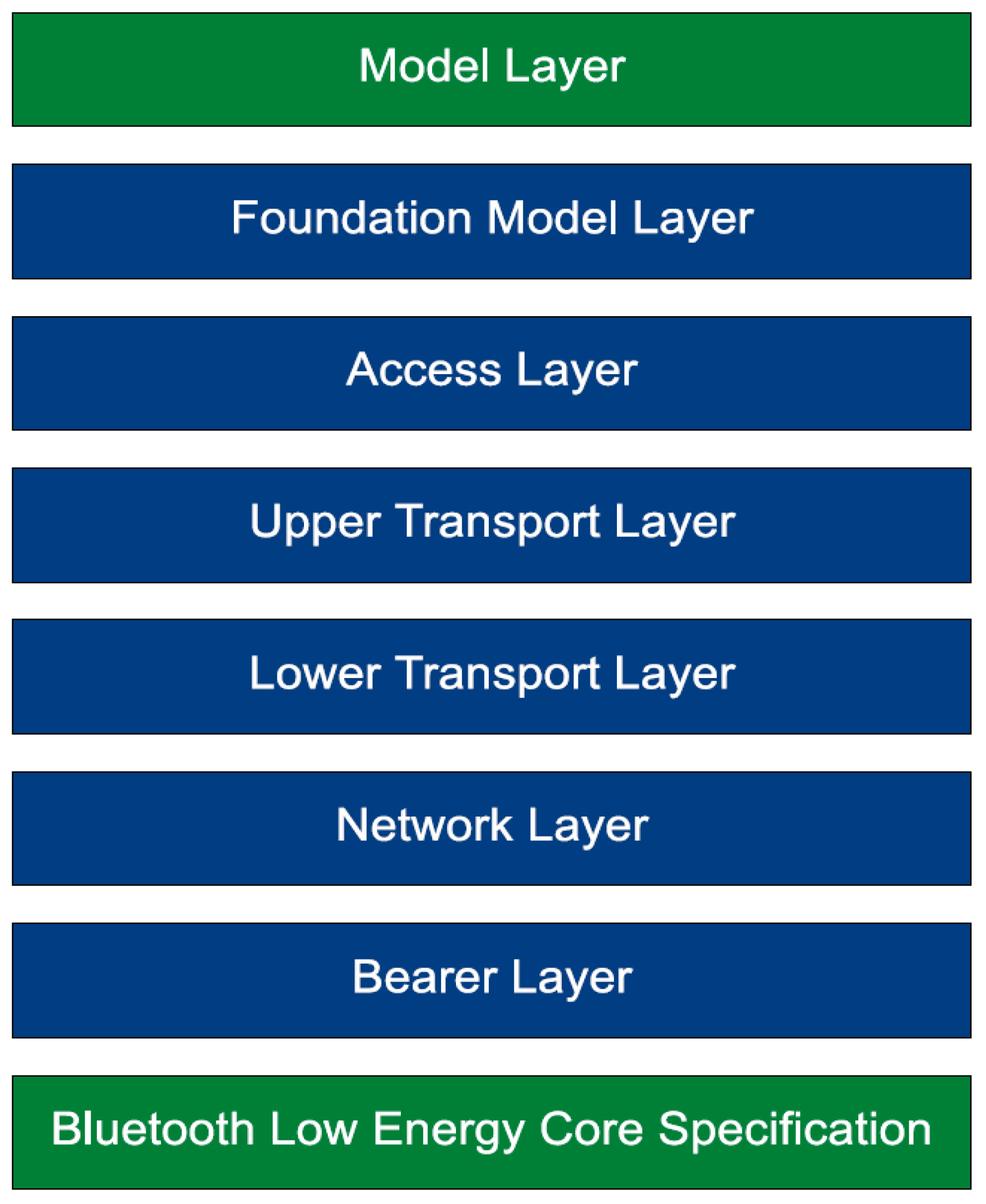
BMP’s specification defines seven layers illustrated in Figure 1 with the following functionalities [7]:
- Model Layer: defines and standardizes typical operations and services for major user scenarios. Several models are defined in [19] which is part of BMP specification.
- Foundation Model Layer: defines states, messages and models related to the configuration and management of mesh networks. They are two obligatory models named ‘configuration’ and ‘health’ models.
- Access Layer: defines data format, encryption and decryption and controls those functionalities. This layer also checks received data in terms of available models, and the network’s and application’s cryptographic keys context.
- Upper Transport Layer: executes cryptographic and authentication tasks in application context to ensure confidentiality of communication.
- Lower Transport Layer: defines and executes segmentation and reassembling tasks and control for large messages.
- Network Layer: defines and process messages addressing and decides if messages are forwarded, accepted or rejected. This layer also executes encryption tasks and authentication of messages in the network context.
- Bearer Layer: makes retro compatibility works and controls BLE’s controller.
As mentioned, the eighth layer in Figure 1 is a BLE controller. Mesh network in BMP is based on managed-flood over broadcast channels. This approach allows extending the range of a message, as long as there is a sufficient density of devices, which can listen to, receive, and relay messages. Flood managing employs network message cache to avoid unnecessary repeated relays and time to live (TTL) to limit hops. A message may be relayed up to 126 hops until it is dropped.
A mesh network in BMP may have subnets. They are managed by its cryptographic keys, i.e., every device in the same subnet knows the same network cryptographic key. Messages are broadcasted in the air, but only devices in the same subnet may decrypt and interpret its content. When a device is invited to make part of a subnet, it receives the subnet’s cryptographic key.
A similar mechanism is used for application level. Different applications have different cryptographic keys, even though devices are at the same subnet. All devices in a subnet may receive a message, but only devices with right application’s cryptographic key can process it. Applications’ cryptographic keys may be configured according to the solution being deployed. Those two cryptographic security layers are mandatory in BMP networks [7].
Both application and network cryptographic keys, as well as devices’ cryptographic keys and addresses, are distributed and managed in a centralized manner through a mechanism named provisioning. This mechanism ensures that there is no duplicated address in a subnet and that all devices in the BMP network are configured accordingly to the solution being deployed. The provisioning mechanism is responsible for detecting unprovisioned devices (which announces its presence using beacons), authorizes them, and gives them all necessary information to become part of a mesh network or subnets. The provisioner device may also configure provisioned devices, allowing them to make part of one or more applications. There should be more than one provisioner device, but BMP does not specify mechanisms of coordination between them.
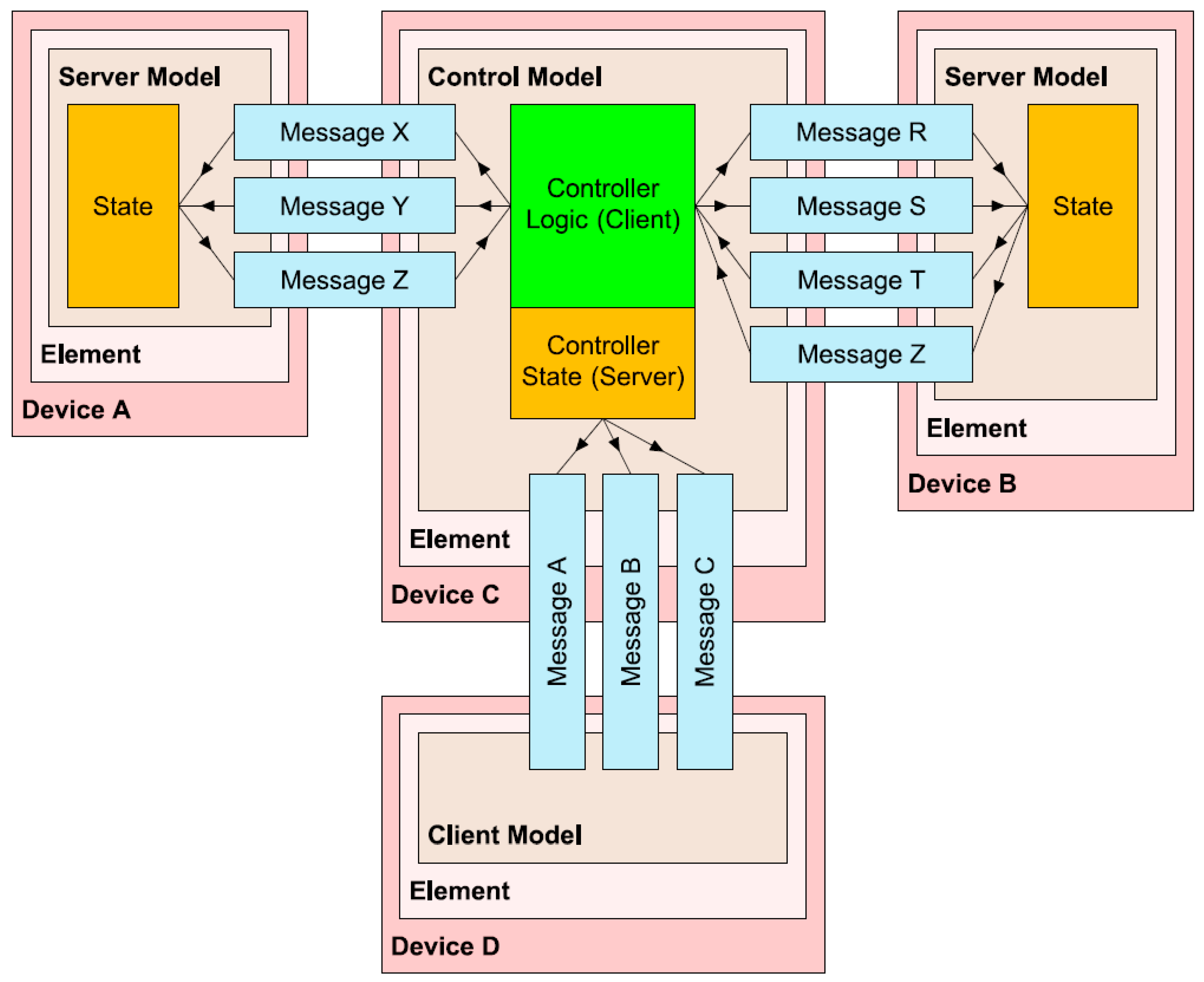
From an architectural point of view, illustrated in Figure 2, devices have one or more elements, which are addressed individually with unicast addresses. Those addresses are used for one-to-one communication and must not be duplicated within a subnet. Elements work as a repository of models. A model defines the behavior of a service and must not be duplicated within an element. Inside elements there are states, which represent data about a given service. Those states may interact with model’s predefined messages. All predefined messages within an element must have different opcodes to avoid ambiguity (implying that the models within an element must be different).
Two instances of a model shall be placed in different elements, when necessary. There are many predefined models in [19] dedicated to most common services and use cases. User-defined models may also be created. Note that all messages in BMP networks are exchanged between models, that constrain and define a service behavior, through its predefined messages.
Beside an element’s unicast address, models may be configured to publish in or subscribe to multicast addresses. Therefore, models may publish messages into a multicast address and every model that subscribe on that address will receive a copy of that message. This method is called the ‘publish-subscribe’ paradigm. Communication is made under a client-server paradigm, i.e., the device should have the appropriate model (with appropriate predefined message opcode) to send, receive, and process messages.
3. Materials and Tools
The following subsections describe material and tools employed in building this proposal. Nordic nRF52832 System on Chip (SoC) microcontrollers embedded in ReadBear nano v2 devices were used together with Nordic Software Development Kits (SDK) to build and demonstrate this proposal. This Nordic solution is qualified for BMP specification [20], i.e., it implements BMP stack and functionalities as specified.
3.1. Employed Devices
The nRF52832 SoC is a powerful, highly flexible ultra-low power multiprotocol SoC with support to multiples wireless communication protocols in ISM band, including BLE [21]. It counts with a 32-bit ARM Cortex M4F working on a 64 MHz clock; 512 Kbytes of flash and 64 Kbytes RAM memory; and several others features like analog–digital conversion, true random number generator, timers, and debugging interfaces. Both of the devices described in the following subsections employ this SoC.
3.1.1. RedBear Nano v2.0
BLE Nano 2 is the smallest BLE SoC development board, only 18.5 × 21 mm [22]. This module supports all advanced features offered by Nordic nRF52832 SoC, although only a few pins are available [23]. The application could be developed using Nordic’s SDK, mbed.org or RedBear open-source Arduino Library for nRF5x. It works along with a DAPLink board that is used to load code and to debug applications in Arduino’s integrated development environment (IDE).
Those devices were programmed using Nordic’s SDK and were employed to demonstrate mesh networks’ range extending and relaying features.
3.1.2. nRF52 Development Kit
The nRF52 DK board can be used as a development platform for the nRF52832 device [24]. It also supports all advanced features offered by Nordic nRF52832 SoC and has onboard programming and debugging solution. Beside it, the nRF52 DK board has LEDs, buttons and interfaces connectors integrated into it. It works with J-Link driver which allows programming and debugging on SEGGER Embedded Studio (SES) IDE through virtual COM port communication. Programming could also be done using GCC compilers or others IDEs like IAR or Keil μVision.
This device was programmed using SES and Nordic’s SDK and was used to collect data through J-Link debugger in SES and as BLE sniffer.
3.2. nRF5 SDK for Mesh
Nordic’s SDK has evolved to follow BMP specification since its initial drafts [6]. The nRF5 SDK for Mesh is Nordic Semiconductor’s implementation of the BMP specification. It allows applications to utilize the features provided by the BMP when running on Nordic’s nRF5 series chips [20].
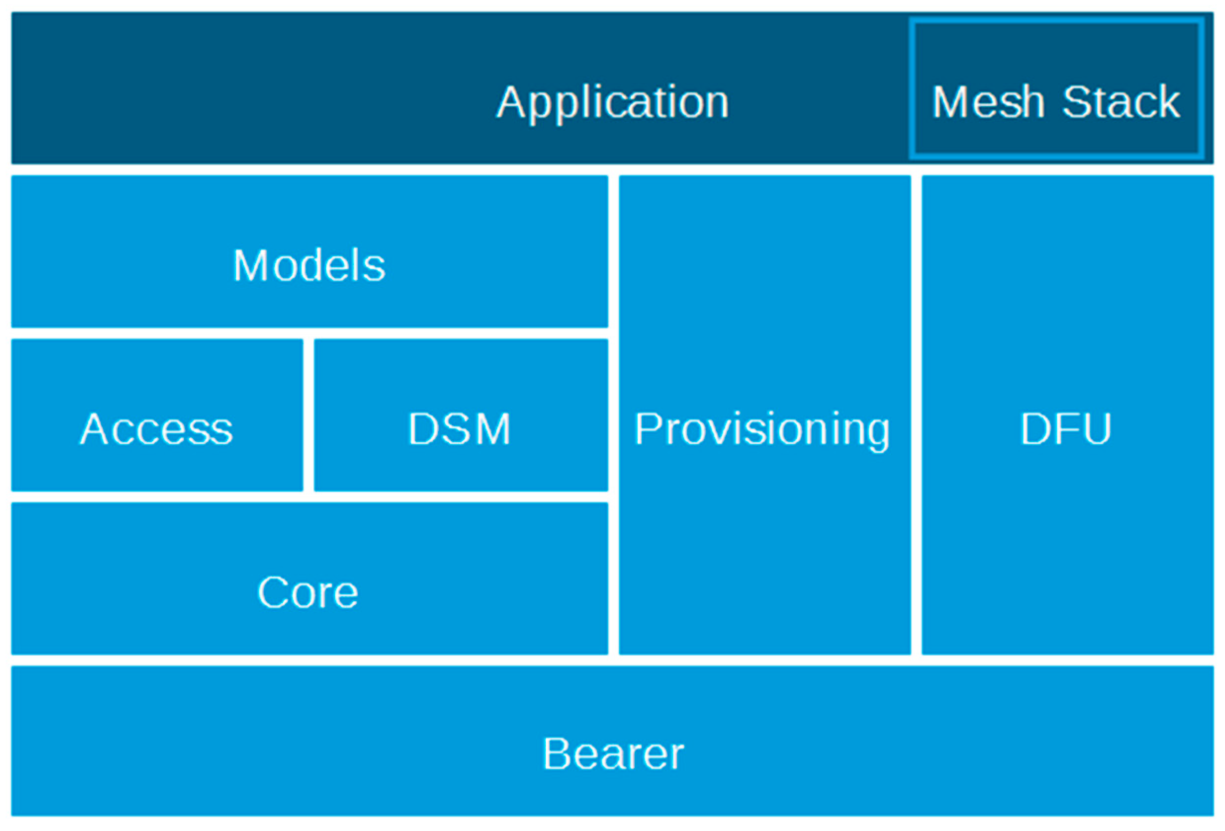
This SDK implements the BMP stack in the following block structure, illustrated in Figure 3:
- Models: define the behavior and communication formats of all data that is transmitted across the mesh. Equivalent to BLE’s GATT services, they are independent, immutable, and implement specific behaviors or services. There are only mandatory models (‘configuration’ and ‘health’) in the SDK version used for this work, but new personalized models may be implemented.
- Access: controls device’s models by holding references to them, to their acceptable messages and configuration. It forwards received messages to appropriate model implementations based on their opcodes.
- Device State Manager: stores encryption keys used by the mesh stack and makes them available to use whenever needed. It also keeps models’ applications keys and publishes addresses.
- Mesh Core: embraces BMP’s network and transport layers and executes all mesh security and encryption tasks. It is also responsible for segmentation and the reassembly of messages, checking addresses and cryptographic context of messages, and the relay of messages when necessary.
- Provisioning: takes care of both sides of the provisioning process, responsible for adding devices to the mesh network. This functional block provides new devices with a range of addresses for its elements, network’s and device’s cryptographic keys.
- Bearer: controls the BLE’s controller (the low-level radio) and enforces compliance for packet formats and timing.
- Device Firmware Upgrade (DFU): is a Nordic proprietary feature that allows secure and relentless firmware update for all devices in a network.
- Mesh Stack: takes care of stack and device initialization in a high-level of abstraction.
nRF5 SDK for mesh version 2.0.1 was used in the elaboration of this proposal. This SDK must be used along with a nRF5 SDK, in order that version 15.0.0 was used. nRF5 SDK provides a rich developing environment and access to all the advanced features of nRF53832 SoC by including a broad selection of drivers, libraries, SoftDevices, and radio protocols [25]. Both SDKs are based in C programming language and are available on Nordic’s websites for free. The following subsections give more details about how relevant BMP features are implemented in Nordic SDK for mesh [20].
3.2.1. Provisioning and Configuration
The initialization of the BMP network is divided into two steps named provisioning and configuration. All devices that want to participate in the BMP network must be provisioned. In this step, new devices receive the following mandatory information:
- A device cryptographic key used to authenticate messages and to securely encrypt one-to-one communication;
- Some sequential unicast addresses to all its elements. The device will receive as many unicast addresses as elements on it;
- A network cryptographic key needed to allow communications over the BMP network. More keys may be added later in configuration step, depending on the application being deployed.
The provisioner device should keep track of all this data to correctly provide (and configure) new devices. Provisioning process in nRF SDK for mesh is done as specified in BMP specification. Most of the job is done by the functional block of nRF SDK for mesh stack named ‘provisioning’, with almost no participation of the application layer.
The provisioning step was divided into five sub-steps. In the first, unprovisioned devices announce their presence using beacons. Next, the application requests provision to a specific device and a link is established. In the third step, a way of authentication is chosen based in both provisioner and provisionee capabilities. This nRF SDK for mesh version 2.0.1 only supports the static provisioning capability, which is based on a static predefined and pre-shared key. Then, the new device is authenticated and authorized. Provisioning data is finally exchanged in the last step and the link is closed after confirmation.
Devices are not supposed to execute service discovery by themselves [7] so the configuration step is also required. The provisioner is the only device a recently provisioned device knows. Therefore, configuration is normally done by provisioner as well. In this step, devices receive applications’ cryptographic keys and their models are configured with addresses to publish into and to subscribe for. These addresses may be of unicast or multicast type. Configuration is made through configuration server and client models as specified in BMP specification. Many others parameters of application operation over BMP network can be managed using those models, including TTL, proxy feature, and relaying.
3.2.2. Customized Models
Models are used to define states, behaviors, and message formats that allow interaction between devices in a BMP network. Only obligatory models are available in Nordic’s nRF5 SDK for mesh version employed on this proposal. However, new customized vendor models may be created. Customized models are created by defining a set of data structures and callback functions that are bound to the stack through functions pointers set on model initialization.
First of all, messages and respective opcodes should be defined based on model purpose. Callback functions following a given signature (defined in access API) should be created to each opcode in order to implement the model’s desired behavior. Functions and opcodes should then be appropriately associated in a list structure for model initialization. Those functions may interact and update service states, which should be arranged in another data structure. Messages’ data should also be formatted by defining others data structures.
In Nordic’s approach, the functions defined so far lay on a model layer and have the main purpose of casting message data from access layer into a defined format and/or translate it into states and then forward it to application layer; or fetch from the application required state data to answer a request message. However, acknowledge behavior should be implemented in the model layer. To achieve this, a set of function signatures should be defined in order to allow later application binding, similarly to what is done between access and model layers. Those functions should then be implemented in the application layer and be provided in model initialization, along with the element index that the model will belong to.
Finally, a set of functions (the model API) should be provided to allow the application layer to send messages into the mesh network (e.g., to publish a state change) and to appropriately initiate and allocate model.
3.3. SEGGER Embedded Studio
The SEGGER Microcontroller Company offers full-range components for a development process including hardware, software and tools. It also provides professional development and production solutions for the embedded market with several years of expertise [26].
Its Embedded Studio is a powerful C/C++ IDE for microcontrollers. It is specifically designed to provide users with everything needed for professional embedded C programming and development, including integrated J-Link debug probe functionality.
The SEGGER Embedded Studio for ARM version 3.34a with an educational and non-commercial license was used to program and compile this proposal and to capture mesh running time data through nRF52 DK debug interface using their integrated J-Link debug probe [24].
3.4. Softdevice
A ‘softdevice’ is a precompiled protocol stack library for the nRF52832 SoC that implements BLE functionality [27]. This component is independent of application development and may be found in SDKs packs. It is automatic and safely loaded along with compiled application in nRF52 DK using SES J-Link. For Redbear devices, however, compilation resulting HEX file should be manually merged with softdevice before loading. It was done using Nordic’s mergehex tool (more info about that tool may be found in [28] and version 9.7.2 was used) and the resulting HEX file was loaded manually.
Softdevice S132 v6.0.0 was used to make BLE stack functionalities available in both employed devices. This softdevice version was chose based on nRF52832 compatibility.
3.5. nRF Sniffer
The nRF sniffer is a tool for debugging BLE applications by detecting packets on air. When developing a BLE product, knowing what happens over-the-air between devices can be helpful. By default, the Sniffer detect nearby BLE devices that are advertising, providing the Bluetooth Address and Address type, complete or shortened name, and RSSI.
This Nordic sniffer solution is composed by a pre-compiled firmware that should be loaded on nRF52 DK, and extension files to Wireshark [27]. Once Wireshark is correctly configured, it allows for the capture, display, and analysis of BLE packets in real-time. Wireshark Version 2.4.6 and the nRF Sniffer version 2.0.0-1 beta were employed due to compatibility issues.
4. Methodology
This proposal was constructed with a focus on a hypothetical scenario. With the spreading of IoT and dissemination of WSN across smart cities, vehicles (and any other connected devices) may be equipped with several sensors. These vehicles may sense their tracks in different ways such as road quality, traffic intensity and delay, signaling and lighting fault, air and sound pollution, rain, inundation and blocking, and many other city metrics. Some of those metrics may substantiate real-time decisions like routing or be used for long-term decisions about maintenance and management actions, accordingly to a smart city’s functionalities.
This scenario may reduce investment in dedicated infrastructure to collect sensors’ data inside a city at the same time that expand and extend area coverage. It works like a swarm in which data may be collected from the environment, shared, imported and exported to other groups, and be transported and delivered for further processing. Therefore, only a few extract, transform, and load (ETL) stations should be necessary to collect data for long-term decisions.
It should be noted that swarm mobility brings up many other challenges related to swarms networks formation, merge, entry and exit. This present proposal will consider BMP applicability on described scenario only. Mobility and ETL methods will not be considered in this work.
4.1. Smart City Device Provisioning and Configuration
The first step of provisioning is beaconing. Unprovisioned smart city’s devices announce their presence using beacons that carry their label UUID with a predefined fixed prefix. UUID labels are made of 128 bits from which 32 most significant bits were chosen to hold prefix. The last bits were left free and were randomly initialized. The provisioner will look for this prefix in beacon packets when inviting devices to join the smart city mesh network.
The supported authentication method is static, so a fixed static key was provided to all devices. After inviting devices to mesh network, the provisioner will check this key to authorize an authenticate devices. Once it passes authorization, it will receive the needed information. Provisioning gives to a device a network and a device cryptographic key and addresses to its elements. Only after this may configuration take place.
All devices will receive the same network cryptographic key, so they all may work as relay. Smart city’s services will be grouped in one application, i.e., all smart cities’ model will be configured with the same application cryptographic key. Cryptographic keys are randomly generated by provisioner.
The provisioner will get the device’s composition data to look for smart city models’ IDs and configure them with the application cryptographic key and a multicast address to publish in and subscribe for. To make provisioning as flexible as possible, each model (which represents a smart city’s service) will share, publish, and subscribe in a given address that is equal to the smart city’s model ID. This approach aims to allow any smart city’s service to work without requiring previous provisioner knowledge.
In brief, smart city’s devices should ensure they have:
- Smart city label UUID prefix (on that proposal was used 0x43495459 that means “CITY” in ASCII code);
- Right 128 bits authorization key preprogrammed (which was defined in a common library file and loaded into devices’ programming project);
- Smart city’s model IDs that correspond to multicast addresses (which starts in 0xC000).
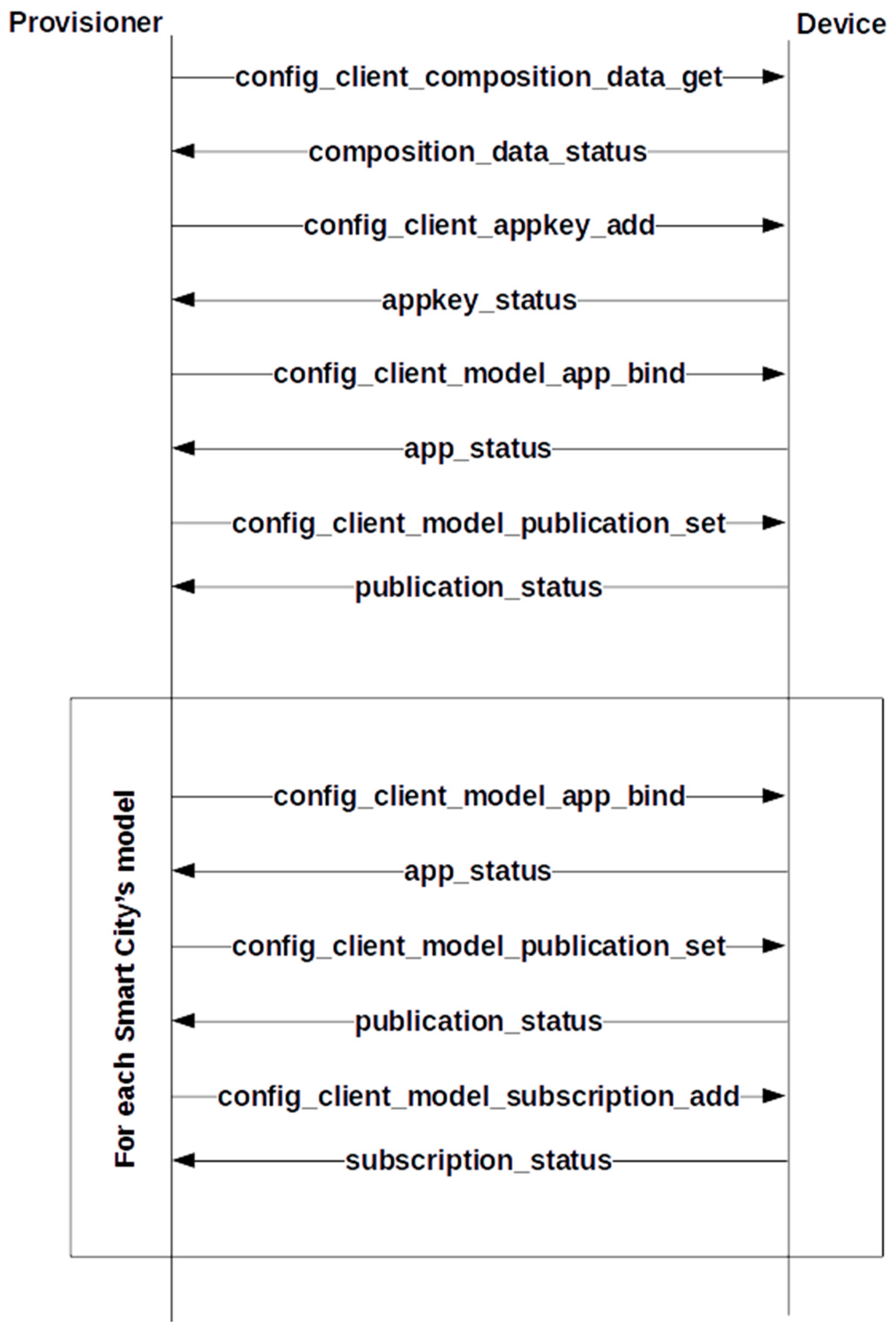
Configuration works based on a state machine illustrated in Figure 4 in which the provisioner sends a configuration command and advances when right confirmation is received. Those steps take place after provisioning is complete. State machine aborts when an error is reported. The provisioner may try again later. Steps include getting composition data, sharing application cryptographic key, binding it to a model, setting model’s publication address, and setting the model’s subscription address. Those three last configuration steps are repeated for each smart city model present in the device. After that, the device is ready to participate in the proposed smart city’s application over the BMP network.
4.2. Smart City Models
Initially, a simple smart city model was created to hold basic information that was thought to be essential to smart city’s services in the described scenario: geo-localization and time. This model was designed to have three messages as stated in Table 1 with related opcodes and a brief description.
All messages were generated in an unreliable way (without confirmation) to avoid gossip in the network, especially in high-density ones. Flooding and multicasting with a high TTL (the maximum was used) increasing the probability of packet delivery ratio on this scenario, so this approach was not taken as a disadvantage.
It is reasonable that only devices with sensors may generate SMART_CITY_SET messages and answer SMART_CITY_GET requests. In fact, SMART_CITY_GET request message should trigger the publication of a SMART_CITY_SET message from sensor devices with the most recent data about a given service. A SMART_CITY_SET message is also supposed to be triggered by a service’s state change. Finally, SMART_CITY_SHARE messages are periodically generated by any device to share historically learned or captured data about a given service. The period was set to be one second.
Message format and service state data structures were set to be the same, i.e., the data structure to hold service state being the same used to format messages. The SMART_CITY_GET request message carries no data. Geo-localization was formatted as two float numbers with 32 bits of precision for longitude and latitude, while time was formatted as a 64 bits UNIX timestamp. Fictitious data was used to initialize them and does not represent the actual location or time of testing. Based on BMP standard [7], 364 octets of 380 will be left free in payload to carry service specific data. It is worth noting that fragmentation may occur if necessary and is automatically controlled by a core functional block (illustrated in Figure 3).
After defining this simple, basic model, another one was made to extend it with the same basic behavior. That second model was designed to carry information about a traffic light service. Beside essential data, a traffic light ID coded into a 16 bits integer, the traffic light state and the time in seconds until the next state change coded in another 16 bits integer as defined in Table 2 where format notation is binary.
Note that the three most significant bits represent traffic light state and ‘x’ should be replaced by interval until the next state change, as proposed. The remaining time should be ignored in TRAFFIC_LIGHT_FAIL state. The traffic light ID was randomly defined by a sensor device.
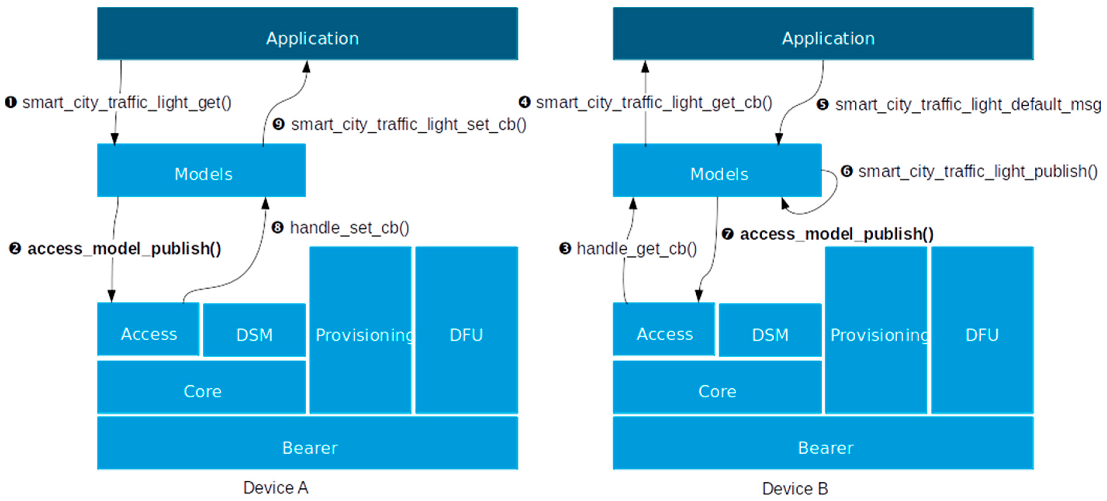
All other required data structures and functions were defined to complain about Nordic’s framework for creating, initializing, and using customized models. The resulting stack architecture is illustrated in Figure 5 where callback sequence shows a SMART_CITY_GET message behavior. Note that a SMART_CITY_SET message is triggered in response.
4.3. Additional Programming
One of the provided examples in Nordic’s SDK for mesh pack was used as a starting point. The application layer has almost no interaction with the provisioning process. Most of the job is done by provisioning functional block and just a few adjustments were enough. Label UUID prefix and static authorization key should be indicated using API. Once service is started, scanning may be triggered by timers.
Configuration is a little trickier. Configuration state machine must be carefully indicated in the right order. Confirmation codes must be checked in order to determine the next step. The right configuration command in its API must be invoked in each step. The configuration’s state machine is commanded by confirmation responses starting with provisioning complete confirmation. For demonstration purposes, just one employed device held those functionalities.
The application layer was further developed for remaining devices to execute service. For demonstration purposes, two kinds of devices were created: ‘full’ and ‘no_sensor’. ‘Full’ devices have a state machine illustrated in Figure 6 that is commanded by a timer to take care of traffic light states and generate data about the service. It may also receive and generate all three types of messages defined in Table 1. ‘No_sensor’ devices only consume and share data. An array was provided on both to hold historical learned data to be shared later using SMART_CITY_SHARE messages. It worth noting that all devices have obligatory models.
As first results came up, an additional programming was done in order to insert another provisioner in demonstration (reasons will be discussed in results section). Network and application cryptographic keys were set to be static and equal on both provisioners.
5. Results
The topology employed to collect results is illustrated in Figure 7. The first thing noted was that devices may provide and configure themselves. Functions invoked in the reaction of provisioning and configuration messages and commands are available in API and may be used e.g., on the application layer. In provisioner specific cases, it must be part of a mesh network, so it has to provide itself to start mesh network. It was also noted, however, that the centralized management of needed information is a must to ensure network security and addressing mechanisms.
Centralized cryptographic keys may be randomly generated in mesh initialization, instead of using a static, preprogrammed, fixed key that may be easier brute forced. In other words, a centralized management ensures not only stronger keys usage, but also that all devices will receive the same keys and communicate with each other as stated in BMP specification. Managing addresses in a centralized way also ensures that there will be no duplicated unicast address in the network. Multicast addresses may be previously known, as proposed here, and be self-configured.
Provisioners may have low duty cycles. Although they are essential for mesh network initialization, and to give entry to new devices on it, they are unnecessary once the mesh network is already working. If provisioning and configuration is the only functionality of a device, it may go into sleep mode and wake up later for checking new unprovisioned devices. It is worth noting, however, that provisioners may work as relays, so mesh network density must be considered.
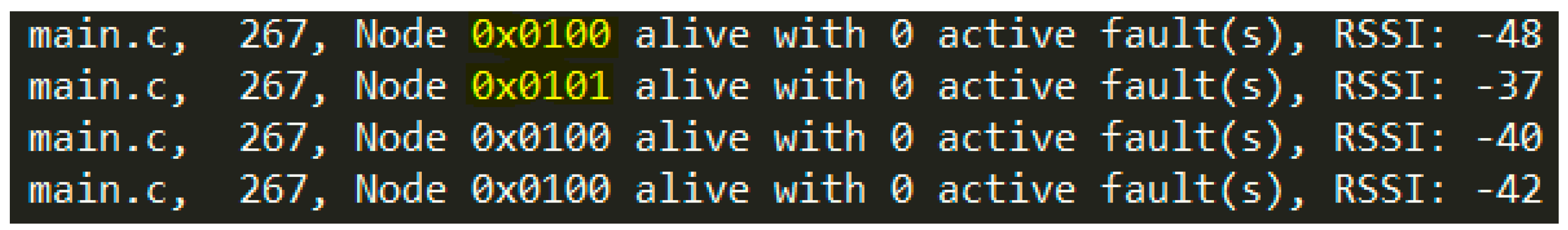
This demonstration did not consider a way to detect mesh network healthy. SMART_CITY_SHARE periodic messages may be used for this. A device may be programmed to restart beaconing or (re-)activated its provisioner feature when mesh network density is becoming unacceptably coarse. The obligatory health model may also be used, as illustrated in Figure 8. This model has some diagnosis messages that allow some telemetry about devices. It also has periodic messages, as shown in Figure 8 that was received by mesh network provisioner. This model may be configured as any other.
It was also noted that a model may be configured to publish to only one address and to subscribe for many addresses. This proposal suggests a standard address for each smart city service in a way that no more than one subscription per service is needed. It simplifies the configuration process.
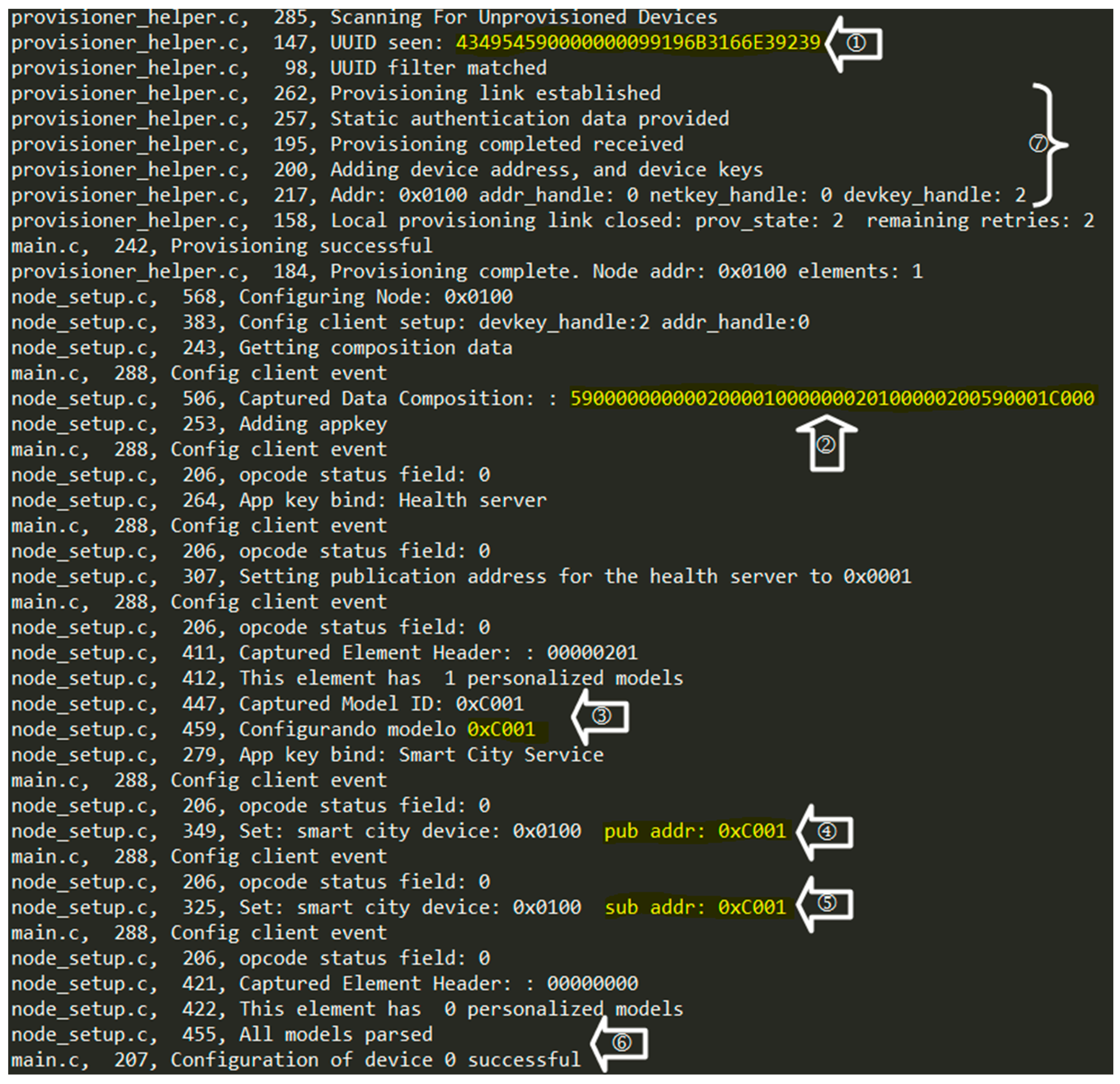
About BMP network operation, Figure 9 shows the provisioner log in which provisioning steps (in ⑦) and configuration state machine (② through ⑤) may be seen. Note that UUID shown in ① has a pre-established prefix, which triggers provisioning. Once provisioning is complete, configuration may take place.
All configuration steps are done using the obligatory ‘configuration’ model. Device composition data showed in ② codes for several information including elements and models present on it. Obligatory ‘health’ model configuration follows. Next, model ID is parsed from composition data in ③ and model is configured to publish and subscribe (④ and ⑤ respectively) on the same address. After configuring all smart city’s model (⑥, device used has only one), the provisioner will look for another unprovisioned device.
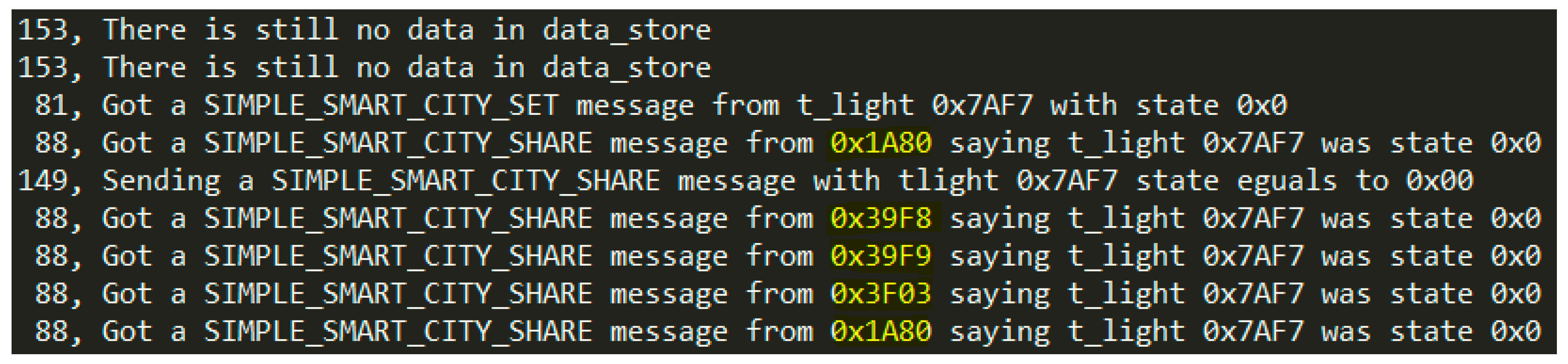
Figure 10 shows the moment a device starts to receive messages from the mesh network. After configuration, it waits until the first messages arrive. Then it starts sharing learned information that may be captured by ETL stations later and submitted for further processing. Figure 10 also shows that there are two active devices sharing data. Note that the first received message is of the SMART_CITY_SET type and comes from a traffic light with ID 0x9239 which is in TRAFFIC_LIGHT_CLOSED state (see Table 2). That message was triggered by a state change.
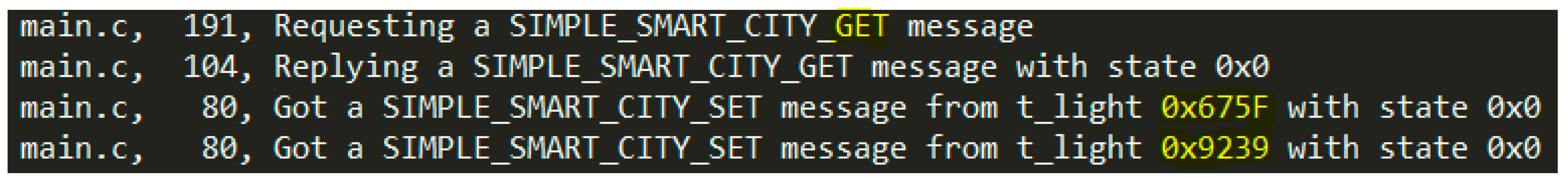
Figure 11 illustrates SMART_CITY_GET message’s behavior. The device request service’s current status and both active traffic light devices in mesh network answer it with SMART_CITY_SET messages. As the device was configured to subscribe in the same address it publishes messages, it received and replied its own request.
It was noted that provisioning only occurs if the provisioner and device communicate directly with each other, i.e., if they both are within radio range. Provisioning is a one-to-one communication that was not relayed by mesh network.
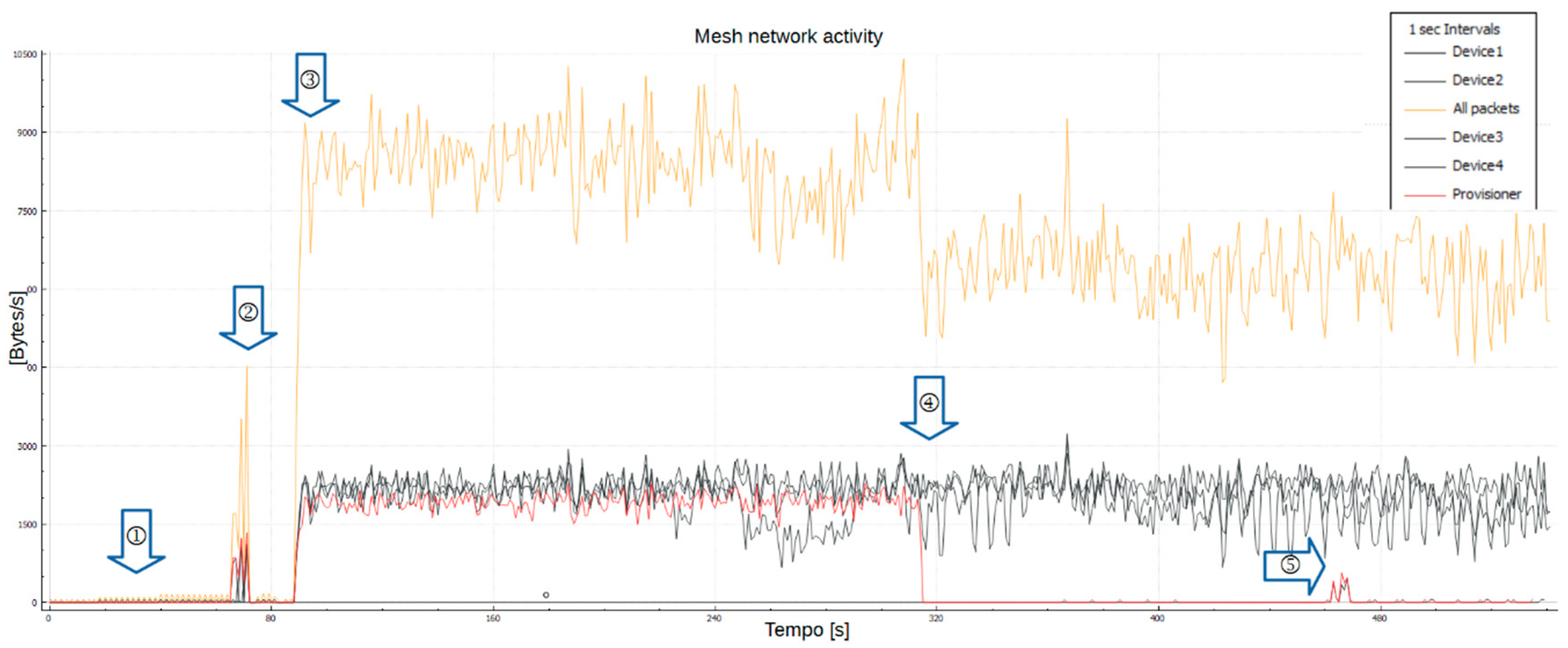
A proprietary sniffer solution by Nordic [27] was used to capture packets. Figure 12 shows network stages captured by sniffer in Wireshark. Stage ① shows unprovisioned devices beaconing. Stage ② shows devices configuration. Provisioning packets were not captured because of sniffer’s particular features that only capture packets in BLE primary advertising channels. Provisioning may occur in the BLE data channels as a one-to-one communication, as noted. Stage ③ shows mesh network message exchange in normal operation. Stage ④ demonstrates that the provisioner is no longer necessary, although it may work as relay. Turning off the provisioner impacted the total flow in the mesh network. Finally, stage ⑤ demonstrates network management based on its cryptographic key. After rebooting the provisioner, it generates a different random network cryptographic key. The device provisioned on that stage could not communicate with others and its captured traffic remains low.
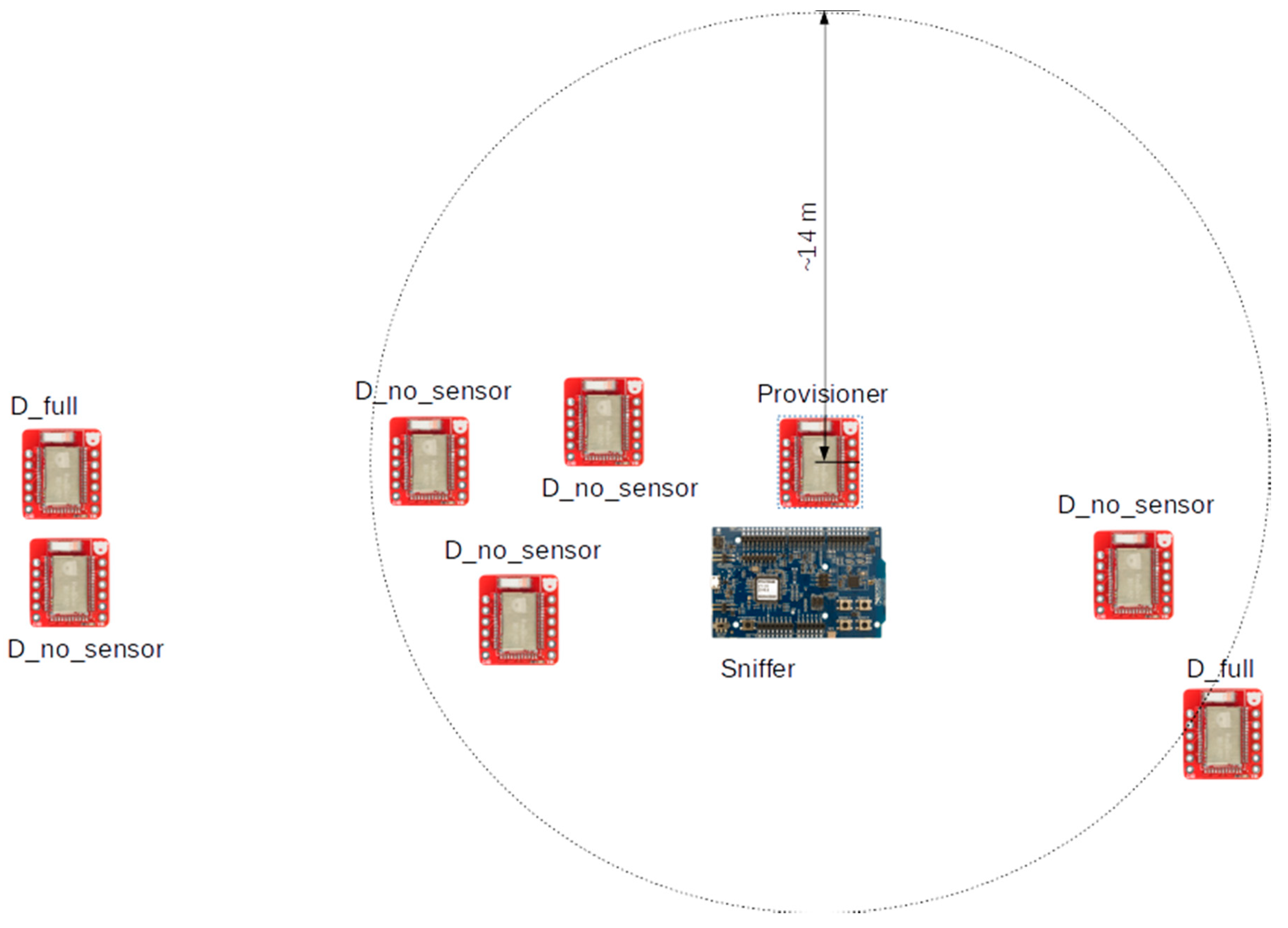
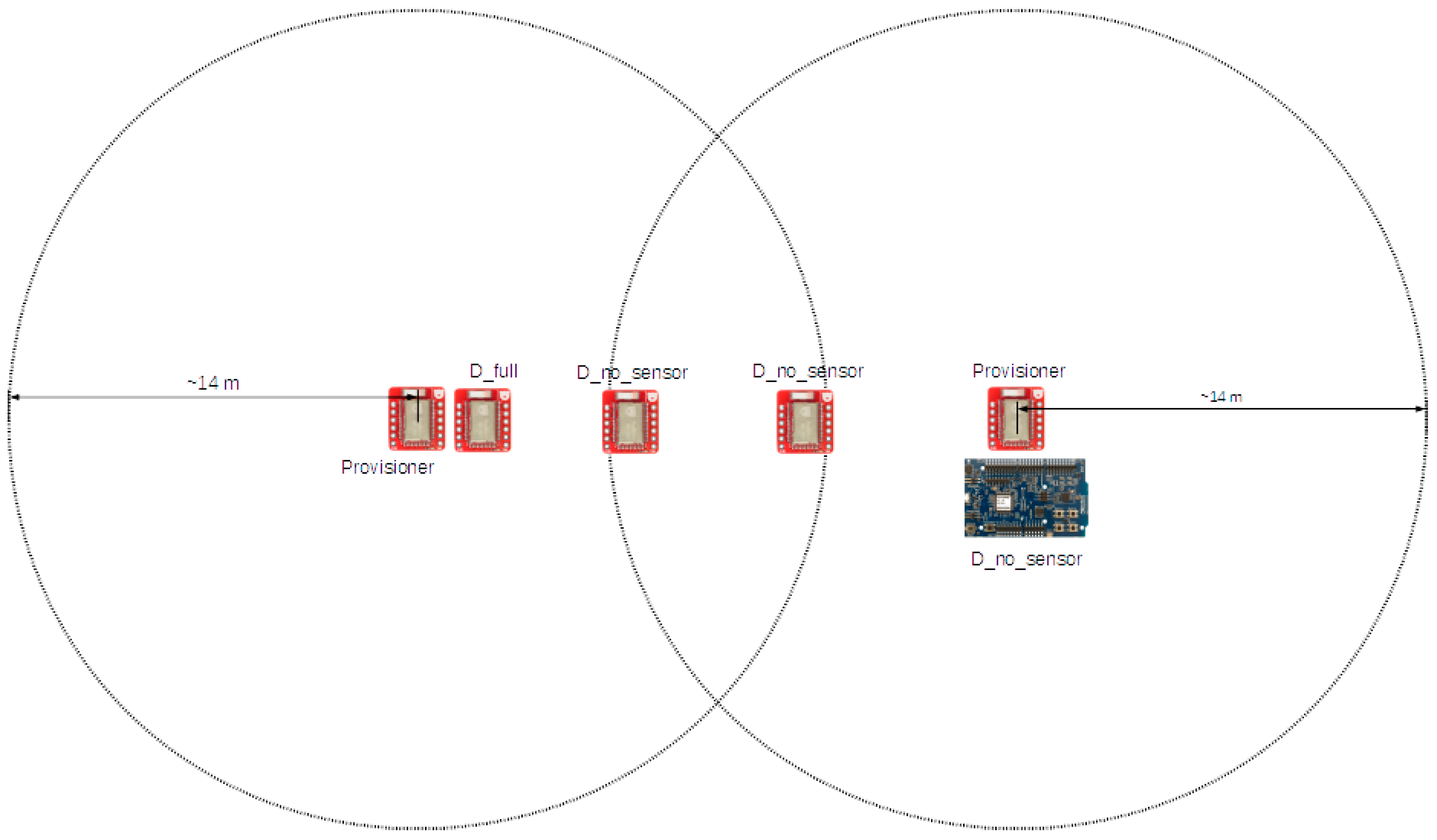
At this point, additional programming was done to introduce another provisioner in the demonstration. It was programmed with static network and application cryptographic keys to be the same in both available provisioners. They were also programmed to have different address spaces. As illustrated in Figure 13, devices were then deployed far enough (radio range was determined to be about fourteen meters) from each other, in a different topology, to ensure that device groups would be provisioned by different provisioners and still communicate through the mesh network. Figure 14 shows mesh network operating with the two addresses space (0×1 and 0×3 addresses prefixes) configured in each provisioner.
It is worth reinforcing that static network and application cryptographic keys were used for demonstration purposes only and may undermine security mechanisms. This demonstrated that devices may communicate with each other as long as they share the same cryptographic keys, even if they have been provisioned by different provisioners. The relay task functionality which increases the coverage of a mesh network was also demonstrated.
Others testing results, such as entire execution logs and Wireshark capture files, are available online at https://github.com/AdonayVeiga/Smart-City-Over-BLE.git.
6. Discussion
This proposal requires standardized label UUID prefix and method of authorization to work in large scale. Only the static method is available in SDK for mesh employed, but BMP specifies several others that may be useful [7]. It may be also done under device and user registering in the future.
This proposal also defines a customized model that may be extended to carry service’s specific data. Only two obligatory models are available in SDK for mesh in the version employed, but many others are defined as part of BMP specification [19]. They may be used directly or be extended to deliver desired data within a smart city context.
Provisioning and configuration mechanisms were identified as crucial for BMP networks. BMP networks are centralized on those roles in a certain manner. Several provisioners and a mechanism of coordination between them will be a must as the mesh network grows. It will also be desirable that devices assume those roles automatically when necessary based on mesh network behaviors, especially in mobility scenarios. Those mechanisms for multiples provisioners should be defined in the future.
It should be also desirable that devices learn new services ‘on-the-fly’. Nordic’s DFU proprietary feature may be used to update devices and achieve this goal relentlessly.
In addition, the methodology proposed here may allow the creation of smart city’s services in an easy and flexible way with minor adjustments for provisioning and configuration processes. Swarm mobility should also be investigated in future works.
7. Conclusions
Smart cities have a long list of challenges to overcome until they may achieve their goal of resource efficiency and citizen welfare. Mesh networks are the most employed approach that confers autonomy, range extension, and no hierarchy. However, they do not yet ensure data security, large interoperability, and multicast communication features.
In this scenario, BMP comes as an opened up industry standard, endorsed by thousands of companies, offering robustness, confidentiality, reliability, and security mechanisms. This work also counted with a highly adherent, qualified solution by Nordic for building applications over BMP networks.
This work demonstrated the most relevant BMP features and the feasibility of using this standard to create smart city applications. A potential framework to achieve this goal was also proposed.
Author Contributions
A.A.V. has done major references researching, writing, programming, testing and results analysis. C.J.B.A. has done major contributions to conceptual design, text reviewing, and results analysis.
Funding
This research received no external funding.
Acknowledgments
This work was supported in part by IoT Laboratory, Department of Electrical Engineering University of Brasilia, Brasilia, Brazil.
Conflicts of Interest
The authors declare no conflict of interest. The funders had no role in the design of the study; in the collection, analyses, or interpretation of data; in the writing of the manuscript, or in the decision to publish the results.
References
- Talari, S.; Shafie-Khah, M.; Siano, P.; Loia, V.; Tommasetti, A.; Catalão, J. A Review of Smart Cities Based on de Internet of Things Concept. Energies 2017, 10, 421. [Google Scholar] [CrossRef]
- García, G.C.; Ruiz, I.L.; Gómez-Nieto, M.Á. State of the Art, Trends and Future of Bluetooth Low Energy, Near Field Communication and Visible Light Communication in the Development of Smart Cities. Sensors 2016, 16, 1968. [Google Scholar] [CrossRef] [PubMed]
- Gokulakrishnan, P.; Ganeshkumar, P. Road Accident Prevention with Instant Emergency Warning Message Dissemination in Vehicular Ad-Hoc Network. PLoS ONE 2015, 10, e0143383. [Google Scholar] [CrossRef]
- Demonstração da Qualcomm Indica Como Serão os Carros Conectados do Futuro. Available online: https://www.tecmundo.com.br/mobilidade-urbana-smart-cities/132144-demonstracao-qualcomm-carros-conectados-futuro.htm (accessed on 18 September 2018).
- Wen, Y.; Anderson, T.A.F.; Powers, D.M.W. On energy-efficient aggregation routing and scheduling in IEEE 802.15.4-based wireless sensor networks. Wirel. Commun. Mobile Comput. 2014, 14, 232–253. [Google Scholar] [CrossRef]
- Darroudi, S.M.; Gomez, C. Bluetooth Low Energy Mesh Networks: A Survey. Sensors 2017, 17, 1467. [Google Scholar] [CrossRef] [PubMed]
- Bluetooth SIG. Bluetooth Mesh Profile Specification, Revision v1.0; Bluetooth SIG Proprietary: Kirkland, WA, USA, 2017. [Google Scholar]
- Bluetooth Mesh Networking. Available online: https://www.ericsson.com/en/white-papers/bluetooth-mesh-networking (accessed on 12 September 2018).
- Baert, M.; Rossey, J.; Shahid, A.; Hoebeke, J. The Bluetooth Mesh Standard: An Overview and Experimental Evaluation. Sensors 2018, 18, 2409. [Google Scholar] [CrossRef] [PubMed]
- Bluetooth Low Energy and Bluetooth 5 Modules, Bluetooth Xpress, SoCs and Software. Available online: https://www.silabs.com/products/wireless/bluetooth (accessed on 12 September 2018).
- Bluetooth Low Energy. Available online: https://www.nordicsemi.com/eng/Products/Bluetooth-low-energy (accessed on 12 September 2018).
- Danebjer, F.; Schreiter, C. Bluetooth Mesh Interoperability Analysis; E-huset: Lund, Sweden, 2017. [Google Scholar]
- Our History. Available online: https://www.bluetooth.com/about-us/our-history (accessed on 12 September 2018).
- Bluetooth Technology Tutorial. Available online: https://www.radio-electronics.com/info/wireless/bluetooth/bluetooth_overview.php (accessed on 13 September 2018).
- IEEE 802.15 WPAN Task Group 1 (TG1). Available online: http://www.ieee802.org/15/pub/TG1.html (accessed on 13 September 2018).
- Bluetooth SIG. Bluetooth Core Specification v 5.0; Bluetooth SIG Proprietary: Kirkland, WA, USA, 2016. [Google Scholar]
- Bluetooth. Available online: https://www.bluetooth.com/ (accessed on 17 September 2018).
- Bluetooth SIG. Bluetooth Mesh Model Specification v1.0; Bluetooth SIG Proprietary: Kirkland, WA, USA, 2017. [Google Scholar]
- nRF5 SDK for Mesh. Available online: https://www.nordicsemi.com/eng/Products/Bluetooth-low-energy/nRF5-SDK-for-Mesh (accessed on 20 September 2018).
- nRF52832. Available online: https://www.nordicsemi.com/eng/Products/Bluetooth-low-energy/nRF52832 (accessed on 21 September 2018).
- BLE Nano v2. Available online: https://redbear.cc/product/ble-nano-2.html (accessed on 21 September 2018).
- nRF5x. Available online: https://github.com/redbear/nRF5x/tree/master/nRF52832 (accessed on 21 September 2018).
- nRF52 DK. Available online: https://www.nordicsemi.com/eng/Products/Bluetooth-low-energy/nRF52-DK (accessed on 21 September 2018).
- nRF5 SDK. Available online: https://www.nordicsemi.com/eng/Products/Bluetooth-low-energy/nRF5-SDK (accessed on 21 September 2018).
- About SEGGER Microcontroller. Available online: https://www.segger.com/about-us/the-company/ (accessed on 27 September 2018).
- S132 SoftDevice. Available online: https://www.nordicsemi.com/eng/Products/S132-SoftDevice (accessed on 27 September 2018).
- nRF5x Command Line Tools. Available online: http://infocenter.nordicsemi.com/topic/com.nordic.infocenter.tools/dita/tools/nrf5x_command_line_tools/nrf5x_command_line_tools_lpage.html (accessed on 27 September 2018).
- nRF Sniffer. Available online: https://www.nordicsemi.com/eng/Products/Bluetooth-low-energy/nRF-Sniffer (accessed on 28 September 2018).
Figure 1.
BMP protocols stack [7].
Figure 1.
BMP protocols stack [7].

Figure 2.
Structural illustration of BMP’s services [7].
Figure 2.
Structural illustration of BMP’s services [7].

Figure 3.
Functional block structure of Nordic’s implementation of BMP stacks (adapted from [20]).
Figure 3.
Functional block structure of Nordic’s implementation of BMP stacks (adapted from [20]).

Figure 4.
Configuration state machine showing configuration’s messages and responses.

Figure 5.
Architectural stack showing SMART_CITY_GET and SMART_CITY_SET callback sequence and behavior (adapted from [20]).
Figure 5.
Architectural stack showing SMART_CITY_GET and SMART_CITY_SET callback sequence and behavior (adapted from [20]).

Figure 6.
Traffic light state machine.

Figure 7.
Topology employed to collect demonstration data.

Figure 8.
Received health model periodic messages sent from devices to mesh network provisioner.

Figure 9.
Provisioner execution log captured in SES shows provisioning and configuration state machines and their steps.
Figure 9.
Provisioner execution log captured in SES shows provisioning and configuration state machines and their steps.

Figure 10.
Smart city device execution log captured in SES shows message sharing behavior.

Figure 11.
SMART_CITY_GET message’s behavior in mesh network, showing request and responses.

Figure 12.
Mesh network activity with its different stages captured by Nordic’s proprietary sniffer solution.
Figure 12.
Mesh network activity with its different stages captured by Nordic’s proprietary sniffer solution.

Figure 13.
Topology employed for additional demonstration with two provisioners.

Figure 14.
Demonstration of management based on cryptographic keys using two provisioners with different addresses spaces.
Figure 14.
Demonstration of management based on cryptographic keys using two provisioners with different addresses spaces.


Table 1.
Simple smart city model messages and opcodes.
| Opcode | Message | Description |
|---|---|---|
| 0xD1 | SMART_CITY_SHARE | Share data learned or captured by device |
| 0xD2 | SMART_CITY_SET | Share a newly captured data in a sensor device |
| 0xD3 | SMART_CITY_GET | Used by a device to request the latest captured data from a sensor device of a given service |
Table 2.
Traffic light state and remaining time format.
| Format | State | Description |
|---|---|---|
| b000x xxxx xxxx xxxx 1 | TRAFFIC_LIGHT_CLOSED | Closed (red) |
| b001x xxxx xxxx xxxx 1 | TRAFFIC_LIGHT_ATTENTION | Attention (yellow) |
| b010x xxxx xxxx xxxx 1 | TRAFFIC_LIGHT_OPENED | Opened (green) |
| b011x xxxx xxxx xxxx 1 | TRAFFIC_LIGHT_FAIL | Traffic light is intermittent or has an internal fault |
1 ‘x’ should be replaced with remaining time until next state change.
© 2018 by the authors. Licensee MDPI, Basel, Switzerland. This article is an open access article distributed under the terms and conditions of the Creative Commons Attribution (CC BY) license (http://creativecommons.org/licenses/by/4.0/).
Share and Cite
MDPI and ACS Style
Veiga, A.A.; Abbas, C.J.B. Proposal and Application of Bluetooth Mesh Profile for Smart Cities’ Services. Smart Cities 2019, 2, 1-19. https://0-doi-org.brum.beds.ac.uk/10.3390/smartcities2010001
AMA Style
Veiga AA, Abbas CJB. Proposal and Application of Bluetooth Mesh Profile for Smart Cities’ Services. Smart Cities. 2019; 2(1):1-19. https://0-doi-org.brum.beds.ac.uk/10.3390/smartcities2010001
Chicago/Turabian StyleVeiga, Adonay A., and Claudia J. B. Abbas. 2019. "Proposal and Application of Bluetooth Mesh Profile for Smart Cities’ Services" Smart Cities 2, no. 1: 1-19. https://0-doi-org.brum.beds.ac.uk/10.3390/smartcities2010001