Article

Modeling and Simulation of Particle Motion in the Operation Area of a Centrifugal Rotary Chopper Machine

1
Department of Agricultural, Forestry and Transport Machines, University of Life Sciences in Lublin, 20-612 Lublin, Poland
2
N.V. Rudnitsky North-East Agricultural Research Institute, Kirov 610007, Russia
3
FSBEI HE Vologda State Dairy Farming Academy (DSFA) named after N.V. Vereshchagin, Vologda—Molochnoye 160555, Russia
*
Author to whom correspondence should be addressed.
Sustainability 2019, 11(18), 4873; https://0-doi-org.brum.beds.ac.uk/10.3390/su11184873
Submission received: 11 August 2019 / Revised: 29 August 2019 / Accepted: 30 August 2019 / Published: 6 September 2019
(This article belongs to the Special Issue Sustainable Production in Food and Agriculture Engineering)

Abstract

:
The article presents approaches to the formation of a general computational scheme for modeling (simulating) the particle motion on an axisymmetric rotating curved surface with a vertical axis of rotation. To describe the complex particle motion over a given surface, the fundamental equation of particle dynamics in a non-inertial reference frame was used, and by projecting it onto the axes of cylindrical coordinates, the Lagrange’s differential equations of the first kind were obtained. According to the proposed algorithm in C#, an application was developed that enables graphical and numerical control of the calculation results. The program interface contains six screen forms with tabular baseline data (input) and a table of a step-by-step calculation of results (output); particle displacement, velocity, and acceleration diagrams constructed along the axes of the system of cylindrical coordinates ρ and z; graphical presentation of the generate of the surface of revolution and the trajectory of the absolute motion of a particle over the axisymmetric rotating surface developed in polar coordinates. Examples of the calculation of the particle motion are presented. The obtained results can be used for the study and design of machines, for example, centrifugal rotary chopper machines.

1. Introduction

The manufacturing sector has one of the largest impacts on worldwide energy use and natural resource consumption. Traditionally, research on manufacturing processes was mainly conducted to improve efficiency and accuracy and to lower costs [1]. One of the modern challenges in the field of designing manufacturing systems is to determine the optimal level of their flexibility from the point of view of the production tasks being performed. Whether or not a production process to be executed is capable of achieving the assumed performance parameters depends, among others, on the reliability of the machines and technological devices that make up the system under design [2]. As commonly known, the oldest manufacturing techniques used by humans are the grinding, chopper, and milling processes. Research on grinding tries to enhance economic and ecological properties and performance to extend grinding applications in the overall process chain—on the one hand, in the direction of increased material removal rates, avoiding turning and milling, and on the other hand, in the direction of fine finishing, thus making further abrasive finishing processes, such as lapping and polishing, obsolete [3].
Many factors influence the sustainability of a manufacturing process, and a combination of qualitative and quantitative methods are needed to discover them [4]. To resolve these issues, namely, the identification of the type of underlying impact factors, the uncertainty of the influencing factors, and the incompleteness of the evaluation information, the researchers used the evaluation method with analytical hierarchy process [5,6] and simulations [2,7,8,9] in the manufacturing sector. Sustainability encompasses the three pillars of economic, environmental, and social sustainability [10,11,12]. In the investigation of Ahmad [10], generally, there were approximately 44% (25/57) of highly applicable indicators. Among them, there were 28% (7/25) environmental, 28% (7/25) economic, and 44% (11/25) social indicators [10]. We can, therefore, see that economic and environmental factors are treated on an equal level. Social indicators in sustainable development are highly rated. Nevertheless, in the case of the two previous ones, they are more adequate for production processes, which have a more indirect nature on social impact. Beekaroo et al. [13] revealed an index with nine environmental, four economic, and two social indicators which were pertinent in sustainability measurement.
One of the most commonly used methods focusing on environmental sustainability is the product life cycle assessment (LCA). This method is used in many sectors of the economy [14,15,16] such as energy sector [17,18,19], transport sector [18,19], and food and agricultural industry [20,21]. The limitation of using this method is the need for specific and very detailed databases covering a lot of quantitative data.
Another method uses sustainability indicators (SI). In this method, the indicator can be defined “as a measure or aggregation of measures from which one can infer about the phenomenon of interest” [11]. This method can capture all three dimensions of sustainable development and help with the evaluation on many levels (e.g., enterprises, objects, processes, and products). In particular, for perpetrators with limited means and resources, SI provide a good method of analyzing sustainable development. Enterprises can assess their real situation using indicators, raise awareness, and set targets. The results of a literature review show that energy costs and GHG (Greenhouse Gas) indicators [10,11,13,19,22,23,24,25] are becoming the most commonly used indicators in sustainable planning. On this basis [11,26], four main directions of future research on sustainability indicators can also be mentioned: implementation of new optimization methods; adding further sustainable development indicators; extension of the model on a larger scale of the production system; and loosening certain assumptions. Finding optimal indicators in production processes is not an easy task; generally, we focus on minimizing energy consumption, waste production, improving the efficiency of machinery and equipment, as well as production and logistic processes in a given company. Sustainability indicators are based on measured and/or estimated data that have to be normalized, scaled, and aggregated consistently [27].
The evolution of design criteria for grinding and chopper machines is driven by functional requirements, general trends in machine tools, and cost [28]. The primary functional requirements, as named by Möhring et al. [29], are similar for all machine tools: high static and dynamic stiffness, fatigue strength, damping, thermal and long-term stability, and low weight of moving parts. The grinding and chopper process is carried out in many areas of food manufacturing [30,31,32] and agriculture [33,34,35], as well as in the industrial sector [36,37,38]. The mixing process is highly complicated, with a number of affecting parameters, such as the particle properties, the structure and performance of the mixer, the mixing process parameters, and the particle feeding order [38]. The crushing method and the machinery used for this purpose should be adapted to the type of material being ground and, in particular, to its mechanical properties [33,39].
Laboratories and modern industry require fast and effective grinding in small volumes [40]. In the field of agricultural mechanization, centrifugal chopper machines with a horizontal rotor have recently attracted increasing interest. Their principle of action lies in the acceleration of grains due to centrifugal inertia forces with their subsequent grinding (fragmentation) by impact or cutting [41,42]. This is due to the lower energy consumption for the grinding process in comparison with other choppers (crushers), which, in addition to the direct costs of grain destruction, have the energy costs for drifting whole and crushed grain using air. In centrifugal rotary chopper machines, the material can be supplied to crusher/shredder hammers or to a cutting pair by centrifugal inertia forces created by a horizontally rotating rotor with working elements. In this, one of the key roles of a centrifugal rotary material grinding machine is the distribution bowl or accelerator, which functions to provide a uniform and stable supply of material to the chopper bodies and impart to the material (particles) located on its surface the necessary linear velocity and trajectory of motion. Despite the rotary blenders relying upon the action of gravity to cause the powder to cascade and mix within a rotating vessel, the convective blenders employ a paddle, impeller, blade, or screw which stirs the powder inside a static vessel [43].
Most of the centrifugal rotary grinding machines in their design have a central feed of the material into the accelerator made in the form of a flat disc. However, with this material feed, the acceleration of a particle that is closest to the axis of rotation will be difficult because of the lack of initial velocity and centrifugal forces to overcome the friction forces, which provokes the appearance of a stagnant zone and an increase in the cost of overcoming them. To solve this problem, two approaches can be used: feeding the material with an offset from the axis of rotation, leading to design complexity, or using the reflective surface of the splitter, which is a straight conical surface located coaxially with the axis of rotation, ensuring the separation of the particles to be ground from the axis of rotation and giving them the initial velocity. In centrifugal impact grinders using the “stone-crushing-stone” principle with self-lining, the trajectory of the particles to be ground (milled) is equally important.
Figure 1 shows the rotary chopper machine analyzed in this study.
Figure 2 shows a scheme of self-lining formation in the accelerator.
The main contribution of this study is the modeling (simulating) of the particle motion on an axisymmetric rotating curved surface with a vertical axis of rotation, whose calculation can be used for the study and design of machines, for example, centrifugal rotary chopper machines. A mathematical model of motion was developed on the basis of step-by-step numerical integration of the obtained closed system of differential equations with an equation of constraint describing the surface of revolution. An application based on the algorithm in C# under MS Visual Studio (Microsoft, Redmond, Washington, USA) was developed that enables graphical and numerical control of the calculation results. Moreover, the results of the calculations of the particle motion trajectory and kinematic indicators are presented. The conducted simulation tests show possibilities of improving the process efficiency and shortening the operation times, which results in economic benefits during sustainable manufacturing.

2. Materials and Methods

Hypothesis. One of the methods to achieve this goal takes into account the form of the accelerator, allowing us to set the initial kinematic parameters and particle trajectory, which in turn will affect the geometric dimensions, metal consumption, and technological modes of operation of a centrifugal rotary chopper or its nodes, for example, rotor (crusher) speed and material feed rate, which would then reduce the specific energy consumption per unit of output.
Methods. To solve this problem, we modeled the motion of a particle of the material on a rotating curved surface. To do this, we used the basic law of particle dynamics (dynamics of a material point) and considered the motion of a particle on the surface of an axisymmetric spinning bowl. We used step-by-step numerical integration, which allowed us to obtain data for analyzing the particle.

3. Results and Discussion

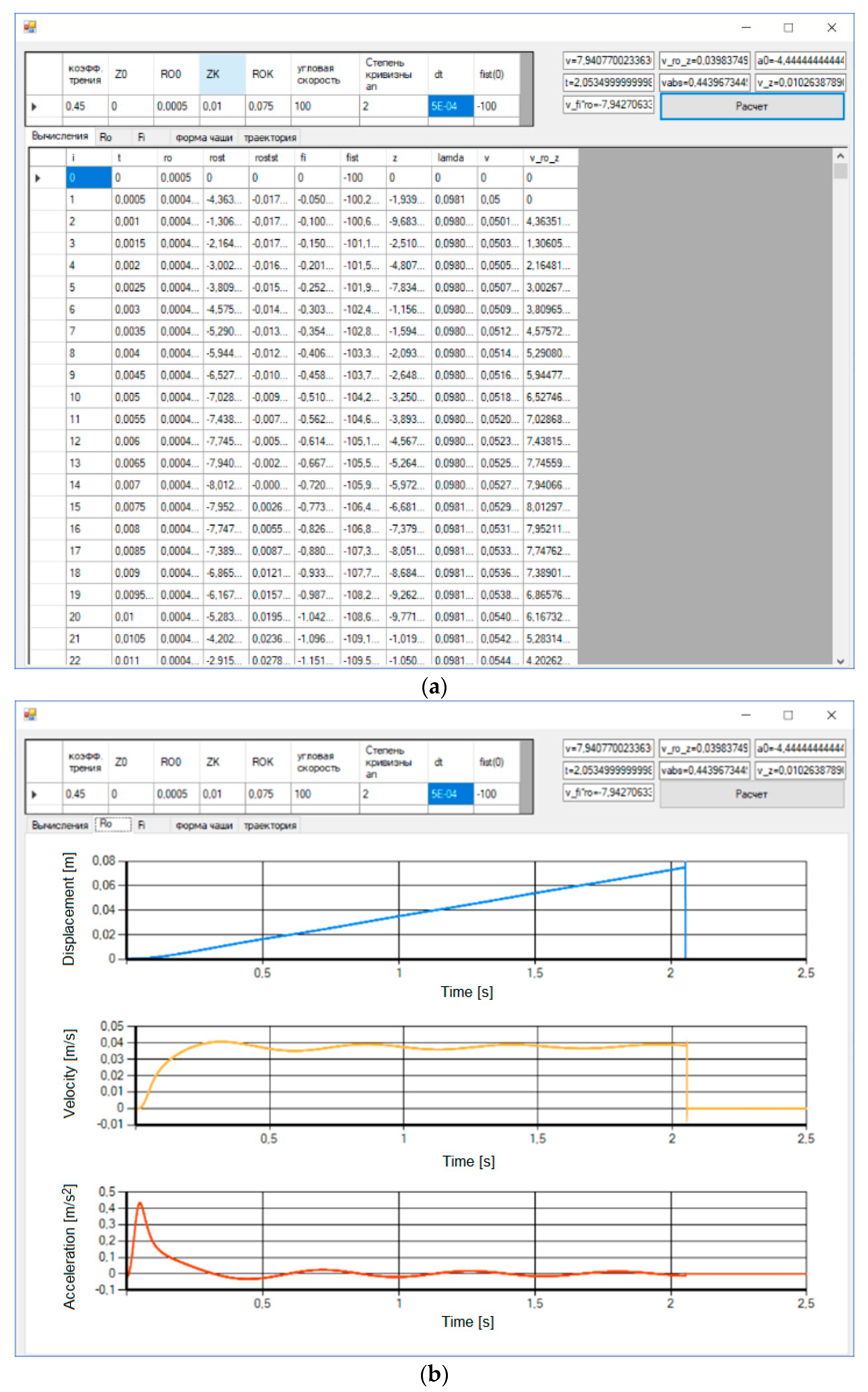
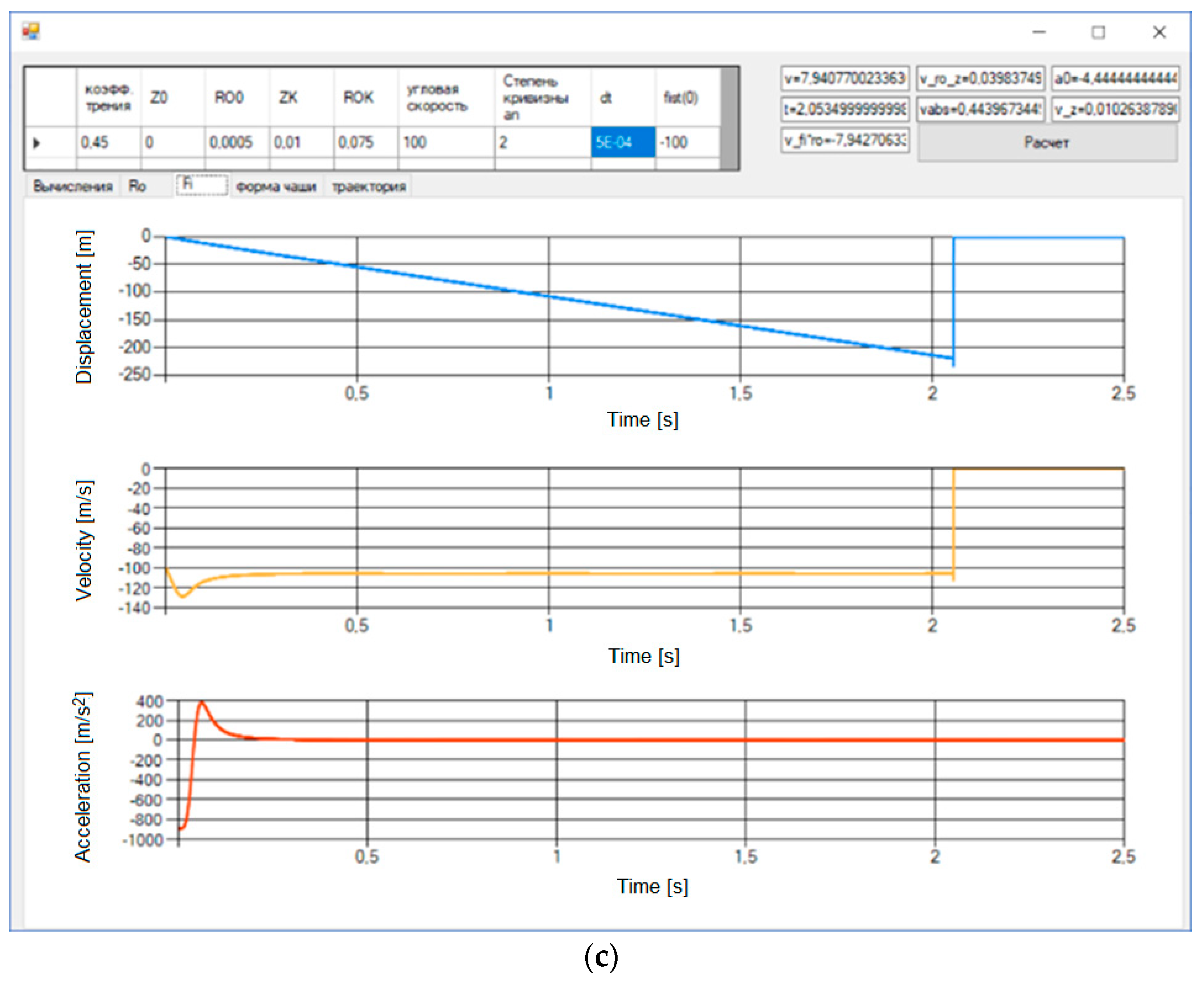
3.1. Modeling Results

The curved surface rotates around the vertical axis z (Figure 3). The equation of the surface is described in cylindrical coordinates by the equation
η(ρ, φ, z) = 0
where ρ is the cylindrical radius, φ is the polar (vectorial) angle, and z is the application (z-axis).
The radius vector of a material point moving on a curved surface in the coordinate axes, rotating with it, is a function of these three coordinates, which can transform over time without breaking Equation (1):
r = r ( ρ , φ , z ) .
The differential equation of the relative motion of a point on a rotating surface is written in vector form [40]
m d 2 r d t 2 = m g + N + F T R + Φ e + Φ c ,
where m is the mass of a particle, d 2 r d t 2 is its acceleration, m g is the gravity force, N is the normal reaction of a bowl surface, F T R is the friction force from the surface directed opposite to the relative velocity of a particle, Φ e is the centrifugal inertial force, and Φ c   is the Coriolis inertial force.
Forces and accelerations on the direction of the cylindrical axes of coordinates are projected. The gravity force is opposite to the z axis,
m g = m g ( 0 ,   0 ,   m g ) ,
where g is free-fall acceleration. The normal reaction of a rotating curved surface is
N = λ · g r a d (   η ) ,
where λ = λ(t) is Lagrange’s indeterminate multiplier [44], grad(η) is the vector gradient to the equation of surface (1), which has projections on the axial cylindrical coordinate system with the φ axis directed perpendicular to the ρ, z, axes and passing through the moving point, so that the axes ρ, φ, z form the right-hand system of vectors:
{ ( g r a d ( η ) ) ρ = η ρ ( g r a d ( η ) ) φ = η φ ( g r a d ( η ) ) z = η z · 1 ρ .
The projections of the normal reaction N are:
{ N ρ = λ η ρ N φ = λ η φ N z = λ η z · 1 ρ .
The modulus of the normal reaction is found by
N = | N | = | λ | ( η ρ ) 2 + ( η φ 1 ρ ) 2 + ( η z ) 2 .
At a constant angular velocity of rotation (spin rate) of the curved surface ω , the centrifugal inertial force Φ e   is directed along the radius ρ in accordance with the result of vector products in its definition
Φ e = m ω × ( ω × r ) ,
where r is determined by Equation (2), then
{ Φ e ρ = m ω 2 ρ Φ e φ = 0 Φ e z = 0 .
Coriolis inertial force Φ c is by definition equal to
Φ c =   2 m ω × v ,
where v is the relative velocity of a material point in the moving axes of coordinates, and the modulus of relative velocity is associated with the cylindrical coordinates by
v = ρ ˙ 2 + ( ρ φ ˙ ) 2 + z ˙ 2 .
Then, the projections of the Coriolis force equal
{ Φ c ρ = 2 m ω φ ˙ ρ Φ c φ = 2 m ρ ˙ ω Φ c z = 0 .
The friction force of a particle on the bowl surface F T R is determined by Coulomb’s law through a normal reaction and it is opposite in direction to the relative velocity:
F T R = | N | f v v
{ F T R ρ = | N | f ρ ˙ v F T R φ = | N | f φ ˙ ρ v F T R z = | N | f z ˙ v .
Let us project Equation (3) on the axis of the moving system of cylindrical coordinates rotating together with the curved surface by using the found projections of all forces:
{ m ( ρ ¨ ρ φ ˙ 2 ) = λ η ρ N f ρ ˙ v + m ω 2 ρ + 2 m ω φ ˙ ρ m 1 ρ d d t ( ρ 2 φ ˙ ) = N f φ ˙ ρ v 2 m ρ ˙ ω m z ¨ = m g + λ η z N f z ˙ v .
Let us transform the second equation of the system, taking into account the projection of acceleration on the φ axis:
1 ρ d d t ( ρ 2 φ ˙ ) = 2 ρ ˙ φ ˙ + ρ φ ¨ .
By bringing all forces to a unit mass of a particle m = 1, we obtain
{ ρ ¨ = ρ φ ˙ 2 + λ η ρ N f ρ ˙ v + ω 2 ρ + 2 ω φ ˙ ρ φ ¨ = 1 ρ ( 2 ρ ˙ φ ˙ N f φ ˙ ρ v 2 ρ ˙ ω ) z ¨ = g + λ η z N f z ˙ v .
To obtain a closed system of equations, we supplement the system (18) with a coupling equation (of constraints) (1) (see supplementary material). Then, four unknown functions ρ(t), φ(t), z(t), λ(t) can be found by solving a system of three differential (18) and one algebraic (1) equations.
In the equation, various forms of execution of the surface of revolution are possible (1). Let us define the coupling equation in the form of an axisymmetric surface described by a power function passing through the given starting and final points of motion, written as
z z K = a 0 + ( ρ ρ K ) n ,
where a 0   is a summand determined from the condition of belonging to a given surface of revolution of the initial point of the trajectory with the coordinates
ρ ( 0 ) = ρ 0 ,     φ ( 0 ) = 0 ,     z ( 0 ) = 0
ρ K ,     z K are coordinates of the final point of the trajectory, where the surface described by Equation (19) ends for all values of the polar (vectorial) angle φ; n is an exponent in the equation of surface, which changes the degree of the bowl concavity and which can be varied to achieve the required parameters of the particle motion.
Thus, the origin of coordinates of the moving frame of reference, in which the particle motion is described, always corresponds along the z axis to the starting point of the motion trajectory, and the parabola vertex in the axial section of the surface of revolution lies on this axis below zero by the value a 0 :
a 0 = ( ρ 0 ρ K ) n .
Let us reduce Equation (19) to the form (1)
η ( ρ , φ , z ) = z z K a 0 ( ρ ρ K ) n = 0 ,
and calculate the partial derivatives in the gradient expression to the constraint surface
{ η ρ = n ( ρ ρ K ) n 1 1 ρ K η φ = 0 η z = 1 z K .
These expressions in Equation (23) should be substituted in the projection of force N   , a normal reaction to the constraint surface in Equation (18).
From the last equation of the system (18) we find the Lagrange multiplier
λ = 1 ( η z ) ( z ¨ + g + N f z ˙ v ) .
Since, when moving along the surface, only two cylindrical coordinates are independent, then for step-by-step numerical integration, we take the first two differential Equations (18) as the basis and calculate the coordinate z and its time derivatives through coupling Equation (22):
z = z K a 0 + z K ( ρ ρ K ) n
z ˙ = n z K 1 ρ K ( ρ ρ K ) n 1 ρ ˙
z ¨ = n z K 1 ρ K ( n 1 ) ( ρ ρ K ) n 2 ρ ˙ 2 ρ K +   n z K 1 ρ K ( ρ ρ K ) n 1 ρ ¨ .
In Equations (24)–(27), the coordinate values ρ and φ, as well as their time derivatives ρ ˙ ,   φ ˙ at the next integration step, are assumed to be equal to their value at the end of the previous integration step. The procedure of numerical integration of the system of Equation (18) was carried out by the method of averaged acceleration [45], using the original algorithmic program for “Windows” coded in C# under MS Visual Studio.

3.2. Results and Discussion

The results of the analysis of the kinematic parameters of the motion and trajectory of the particle, which initiate motion, with no initial linear velocity v 0 and with an angular velocity ω 0 equal in magnitude to the angular velocity of rotation ω e , for different curvilinear surfaces (Figure 4) of the accelerator, are presented in Figure 5. It shows that the use of a concave curvilinear surface (na = 2) allowed to double the value of the acquired velocity v a b s   in comparison with the flat surface (na = 0) and to increase it 1.7 times compared to a conical surface (na = −0.1) at a descent from a rotating surface, which is a consequence of the time spent by the particle on the surface, for example, when na = 2, the time was t = 2.05 s, when na = 0, the time was t = 0.84 s, and when na = −0.1, the time was t = 0.38 s. When the shape of the rotating surface changed from concave na = 2 to convex na = −0.1, the total length of the path traveled by the particle—that is, its trajectory—decreased.
The calculations were carried out for different variable characteristics of the surface, initial indicators of kinematic parameters, and friction coefficient. Figure 6a presents an example of tabular data with the results of calculations and diagrams of changes in the motion trajectory, velocity, and acceleration of a particle along the cylindrical axes ρ and z.
Analysis of the diagrams presented in Figure 6b, c made it possible to note that the particle reached its maximum velocity in 0.313 s, being at a distance of ρ = 0.0092 m from the axis of rotation. At the same time, the subsequent changes in velocity, down to its descent from the concave surface, had a damped harmonic nature.
Thus, curvilinear surfaces of concave nature combining conical and concave surfaces are of great interest for further research. The trajectories of the particles and their kinematic indicators can be used to determine the relationship between the design factors and the process parameters of centrifugal choppers, such as the time when the particle is on a dispensing bowl, the descent velocity of the particle from the bowl, and the shape of accelerating blades.
The ability to achieve the assumed performance parameters of the production process planned for implementation depends on the degree of reliability of the machines and technological devices included in the designed system [2]. Based on previous research [34], it can be confirmed that with the optimal values of the technological process (efficiency, time of a given operation—mixing or mining, coefficient of friction, and particle movement), it is possible to reduce energy consumption. Data on the possibility of improving the operation of production processes of various enterprises in Germany are presented by Steinhofel and others [46]. As we know, many factors influence the production process, for example, technical, economic, and social factors. Due to the above reasons, obtaining such large benefits in the whole production process, where various technological machines operate (technological operations), is difficult; nevertheless, it enables the introduction of sustainable production processes. The conducted simulation tests show possibilities of improving process efficiency and shortening the operation times, which results in economic benefits. The lower energy consumption and the increase in the efficiency of technological processes will also lead to the generation of less post-production waste (ecological benefits), which is in line with the principles of sustainable development.

4. Conclusions

In this study, a closed system of equations was obtained with a coupling equation (of constraints) that allows modeling a particle motion on a rotating surface; when numerically integrating them, it is possible to evaluate the use of a particular accelerator surface of a centrifugal rotary chopper machine to achieve the desired results in terms of downsizing, increasing productivity, or improving the quality of shredding. The use of numerical integration methods allows to consider the influence of physical and geometrical processes and kinematic parameters on the output result, for example, traveling time and velocity in cylindrical coordinates. Thus, the simulation of the particle motion along an accelerator allows choosing rational geometrical dimensions of the chopper machine and its optimal operating practice.

Supplementary Materials

The Supplementary Materials are available online at https://0-www-mdpi-com.brum.beds.ac.uk/2071-1050/11/18/4873/s1.

Author Contributions

Conceptualization, J.C., P.A.S. and I.I.I.; Data curation, A.V.A.; Formal analysis, A.M., A.V.A., A.Y.I. and I.I.I.; Methodology, A.V.A., P.A.S. and A.Y.I.; Resources, J.C.; Software, P.A.S.; Writing—original draft, J.C., P.A.S. and A.Y.I.; Writing—review & editing, J.C. and I.I.I.

Funding

This research received no external funding.

Acknowledgments

We are thankful to the Editor and the reviewers for their valuable comments and detailed suggestions to improve the paper.

Conflicts of Interest

The authors declare no conflict of interest.

References

  1. Linke, B.S.; Corman, G.J.; Dornfeld, D.A.; Tonissen, S. Sustainability indicators for discrete manufacturing processes applied to grinding technology. J. Manuf. Syst. 2013, 32, 556–563. [Google Scholar] [CrossRef] [Green Version]
  2. Gola, A. Reliability analysis of reconfigurable manufacturing system structures using computer simulation methods. Eksploat. I Niezawodn. Maint. Reliab. 2019, 21, 90–102. [Google Scholar] [CrossRef]
  3. Wegener, K.; Bleicher, F.; Krajnik, P.; Hoffmeister, H.W.; Brecher, C. Recent developments in grinding machines. Cirp Ann. Manuf. Technol. 2017, 66, 779–802. [Google Scholar] [CrossRef]
  4. Zhou, Z.; Dou, Y.; Sun, J.; Jiang, J.; Tan, Y. Sustainable Production Line Evaluation Based on Evidential Reasoning. Sustainability 2017, 9, 1811. [Google Scholar] [CrossRef]
  5. Shankar, K.M.; Kumar, P.U.; Kannan, D. Analyzing the Drivers of Advanced Sustainable Manufacturing System Using AHP Approach. Sustainability 2016, 8, 824. [Google Scholar] [CrossRef]
  6. Wu, G.; Duan, K.; Zuo, J.; Zhao, X.; Tang, D. Integrated Sustainability Assessment of Public Rental Housing Community Based on a Hybrid Method of AHP-Entropy Weight and Cloud Model Sustainability. Sustainability 2017, 9, 603. [Google Scholar]
  7. Bardelli, M.; Cravero, C.; Marini, M.; Marsano, D.; Milingi, O. Numerical Investigation of Impeller-Vaned Diffuser Interaction in a Centrifugal Compressor. Appl. Sci. 2019, 9, 1619. [Google Scholar] [CrossRef]
  8. Faria, P.M.C.; Rajamain, R.K.; Tavares, L.M. Optimization of Solids Concentration in Iron Ore Ball Milling through Modeling and Simulation. Minerals 2019, 9, 366. [Google Scholar] [CrossRef]
  9. Koltai, T.; Lozano, S.; Uzonyi-Kecskés, J.; Moreno, P. Evaluation of the results of a production simulation game using a dynamic DEA approach. Comput. Ind. Eng. 2017, 105, 1–11. [Google Scholar] [CrossRef]
  10. Ahmad, S.; Wong, K.Y. Development of weighted triple-bottom line sustainability indicators for the Malaysian food manufacturing industry using the Delphi method. J. Clean. Prod. 2019, 229, 1167–1182. [Google Scholar] [CrossRef]
  11. Joung, C.B.; Carrell, J.; Sarkar, P.; Feng, S.C. Categorization of indicators for sustainable manufacturing. Ecol. Indic. 2013, 24, 148–157. [Google Scholar] [CrossRef]
  12. Krajn, D.; Glavic, P. Indicators of sustainable production. Clean Technol. Environ. Policy 2003, 5, 279–288. [Google Scholar] [CrossRef]
  13. Beekaroo, D.; Callychurn, D.S.; Hurreeram, D.K. Developing a sustainability index for Mauritian manufacturing companies. Ecol. Indic. 2019, 96, 250–257. [Google Scholar] [CrossRef]
  14. Filleti, R.A.P.; Silva, D.A.L.; da Silva, E.J.; Ometto, A.R. Productive and environmental performance indicators analysis by a combined LCA hybrid model and real-time manufacturing process monitoring: A grinding unit process application. J. Clean. Prod. 2017, 161, 510–523. [Google Scholar] [CrossRef]
  15. Machado, C.G.; Despeisse, M.; Winroth, M.; Ribeiro da Silva, E.H.D. Additive manufacturing from the sustainability perspective: Proposal for a self-assessment tool. In Proceedings of the 52nd CIRP Conference on Manufacturing Systems, Procedia CIRP, Ljubljana, Slovenia, 12–14 June 2019; Volume 81, pp. 482–487. [Google Scholar]
  16. Zarte, M.; Pechmann, A.; Nunes, I.L. Decision support systems for sustainable manufacturing surrounding the product and production life cycle—A literature review. J. Clean. Prod. 2019, 219, 336–349. [Google Scholar] [CrossRef]
  17. Piasecka, I.; Tomporowski, A.; Flizikowski, J.; Kruszelnicka, W.; Kasner, R.; Mroziński, A. Life Cycle Analysis of Ecological Impacts of an Offshore and a Land-Based Wind Power Plant. Appl. Sci. 2019, 9, 231. [Google Scholar] [CrossRef]
  18. Wang, R.; Wu, Y.; Ke, W.; Zhang, S.; Zhou, B.; Hao, J. Can propulsion and fuel diversity for the bus fleet achieve the win–win strategy of energy conservation and environmental protection? Appl. Energy 2015, 147, 92–103. [Google Scholar] [CrossRef]
  19. Ventura, J.A.; Kweon, S.J.; Hwang, S.W.; Tormay, M.; Li, C. Energy policy considerations in the design of an alternative-fuel refueling infrastructure to reduce GHG emissions on a transportation network. Energy Policy 2017, 111, 427–439. [Google Scholar] [CrossRef]
  20. Arzoumanidis, I.; Salomone, R.; Petti, L.; Mondello, G.; Raggi, A. Is there a simplified LCA tool suitable for the agri-food industry? An assessment of selected tools. J. Clean. Prod. 2017, 149, 406–425. [Google Scholar] [CrossRef]
  21. Tassielli, G.; Renzulli, P.A.; Mousavi-Avval, S.H.; Notarnicola, B. Quantifying life cycle inventories of agricultural field operations by considering different operational parameters. Int. J. Life Cycle Assess. 2019, 24, 1075–1092. [Google Scholar] [CrossRef]
  22. Helleno, A.L.; Isaias de Moraes, A.J.; Simon, A.T. Integrating sustainability indicators and Lean Manufacturing to assess manufacturing processes: Application case studies in Brazilian industry. J. Clean. Prod. 2017, 153, 405–416. [Google Scholar] [CrossRef]
  23. Skrucany, T.; Ponicky, J.; Kendra, M.; Gnap, J. Comparison of railway and road passenger transport in energy consumption and GHG production. In Proceedings of the Third International Conference on Traffic and Transport Engineering (ICTTE), Lucerne, Switzerland, 6–10 July 2016; pp. 744–749. [Google Scholar]
  24. Skrucany, T.; Semanova, S.; Figlus, T.; Sarkan, B.; Gnap, J. Energy intensity and GHG production of chosen propulsions used in road transport. Commun. Sci. Lett. Univ. Zilina 2017, 19, 3–9. [Google Scholar]
  25. Tucki, K.; Mruk, R.; Orynych, O.; Wasiak, A.; Botwinska, K.; Gola, A. Simulation of the Operation of a Spark Ignition Engine Fueled with Various Biofuels and Its Contribution to Technology Management. Sustainability 2019, 11, 2799. [Google Scholar] [CrossRef]
  26. Akbar, M.; Irohara, T. Scheduling for sustainable manufacturing: A review. J. Clean. Prod. 2018, 205, 866–883. [Google Scholar] [CrossRef]
  27. Singh, R.K.; Murty, H.R.; Gupta, S.K.; Dikshit, A.K. An overview of sustainability assessment methodologies. Ecol. Indic. 2012, 15, 281–299. [Google Scholar] [CrossRef]
  28. Leonesio, M.; Bianchi, G.; Cau, N. Design criteria for grinding machine dynamic stability. Procedia Cirp 2018, 78, 382–387. [Google Scholar] [CrossRef]
  29. Möhring, H.C.; Brecher, C.; Abele, E.; Fleischer, J.; Bleicher, F. Materials in machine tool structures. Cirp Ann. Manuf. Technol. 2015, 64, 725–748. [Google Scholar] [CrossRef]
  30. Madej, O.; Kruszelnicka, W.; Tomporowski, A. Wyznaczanie procesowych charakterystyk wielokrawędziowego rozdrabniania ziaren kukurydzy. Inżynieria I Apar. Chem. 2016, 4, 144–145. [Google Scholar]
  31. Stadnyk, I.; Vitenko, T.; Droździel, P.; Derkach, A. Simulation of components mixing in order to determine rational parameters of working bodies. Adv. Sci. Technol. Res. J. 2016, 10, 30–138. [Google Scholar] [CrossRef]
  32. Tong, J.; Xu, S.; Chen, D.; Li, M. Design of a Bionic Blade for Vegetable Chopper. J. Bionic Eng. 2017, 14, 163–171. [Google Scholar] [CrossRef]
  33. Flizikowski, J.; Topolinski, T.; Opielak, M.; Tomporowski, A.; Mrozinski, A. Research and analysis of operating characteristics of energetic biomass micronizer. Eksploat. I Niezawodn. Maintanance Reliab. 2015, 17, 19–26. [Google Scholar] [CrossRef]
  34. Marczuk, A.; Misztal, W.; Savinykh, P.; Turubanov, N.; Isupov, A.; Zyryanov, D. Improving efficiency of horizontal ribbon mixer by optimizing its constructional and operational parameters. Eksploat. I Niezawodn. –Maint. Reliab. 2019, 21, 220–225. [Google Scholar] [CrossRef]
  35. Rocha, A.G.; Montanhini, R.N.; Dilkin, P.; Tamiosso, C.D.; Mallmann, C.A. Comparison of different indicators for the evaluation of feed mixing efficiency. Anim. Feed Sci. Technol. 2015, 209, 249–256. [Google Scholar] [CrossRef]
  36. Tropp, M.; Tomasikova, M.; Bastovansky, R.; Krzywonos, L.; Brumercik, F. Concept of deep drawing mechatronic system working in extreme conditions. Procedia Eng. 2017, 192, 893–898. [Google Scholar] [CrossRef]
  37. Vitenko, T.; Droździel, P.; Rudawska, A. Industrial usage of hydrodynamic cavitation device. Adv. Sci. Technol. Res. J. 2018, 12, 158–167. [Google Scholar] [CrossRef]
  38. Xiao, X.; Tan, Y.; Zhang, H.; Jiang, S.; Wang, J.; Deng, R.; Cao, G.; Wu, B. Numerical investigation on the effect of the particle feeding order on the degree of mixing using DEM. Procedia Eng. 2015, 102, 1850–1856. [Google Scholar] [CrossRef]
  39. Tomporowski, A.; Flizikowski, J.; Al-Zubledy, A. An active monitoring of biomaterials grinding. Przem. Chem. 2018, 97, 250–257. [Google Scholar]
  40. Camargo, I.L.; Erbereli, R.; Lovo, J.F.P.; Fortulan, C.A. Planetary Mill with Friction Wheels Transmission Aided by an Additional Degree of Freedom. Machines 2019, 7, 33. [Google Scholar] [CrossRef]
  41. Druzhynin, R.A. Improving the Working Process of an Impact Centrifugal Grinding Machine. Ph.D. Thesis, Voronezh State University, Voronezh, Russia, 2014. [Google Scholar]
  42. Stepanovich, S.N. Centrifugal Rotary Grain Grinders. Ph.D. Thesis, Chelyabinsk State Agroengineering University, Chelyabinsk, Russia, 2008. [Google Scholar]
  43. Cho, J.; Zhu, Y.; Lewkowicz, K.; Lee, S.H.; Bergman, T.; Chaudhuri, B. Solving granular segregation problems using a biaxial rotary mixer. Chem. Eng. Process. 2012, 57–58, 42–50. [Google Scholar] [CrossRef]
  44. Nikitin, N.N. The Course of Theoretical Mechanics; Higher School: Moscow, Russia, 1990; p. 607. [Google Scholar]
  45. Timoshenko, S.P.; Young, D.H.; Weaver, W. Vibration Problems in Engineering; Trans. from English; D. Van Nostrand Company INC.: New York, NY, USA, 1985; p. 472. [Google Scholar]
  46. Steinhöfel, E.; Galeitzke, M.; Kohl, H.; Orth, R. Sustainability Reporting in German Manufacturing SMEs. 16th Global Conference on Sustainable Manufacturing—Sustainable Manufacturing for Global Circular Economy. Proc. Manuf. 2019, 33, 610–617. [Google Scholar]
Figure 1. Tornado chopper machine: 1—feed-in tube; 2—case cover; 3—accelerator; 4—accelerating blade; 5—shredding element; 6—electric motor; 7—V-belt drive.
Sustainability 11 04873 g001
Figure 2. Scheme of self-lining formation in the accelerator: 1—a splitter; 2—wear plate; 3—self-lining pocket; 4—carbide blade; 5—descent of the material from the accelerator; 6—accelerator case.
Sustainability 11 04873 g002
Figure 3. Design diagram of the motion of a particle on a rotating curved surface.
Sustainability 11 04873 g003
Figure 4. Variants of generates of the studied curvilinear surfaces of the accelerator.
Sustainability 11 04873 g004
Figure 5. Data for analyzing the velocity and trajectory of the particle motion, which is introduced with no initial linear velocity and with angular velocity equal in magnitude to the angular velocity of rotation for different curvilinear surfaces of the accelerator: (a) na = 2 (concave); (b) na = 0 (straight line); (c) na = −0.1 (conical curvilinear).
Sustainability 11 04873 g005aSustainability 11 04873 g005b
Figure 6. Example of the results of calculations of the particle motion trajectory and kinematic indicators for na = 2; (a) tabular data; (b) diagrams of particle displacement, velocity, and acceleration along the axis ρ; (c) diagrams of particle displacement, velocity, and acceleration along the axis z.
Sustainability 11 04873 g006aSustainability 11 04873 g006b

