Article

Exploring the Potential of Climate-Adaptive Container Building Design under Future Climates Scenarios in Three Different Climate Zones

1
Department of Energy and Built Environments, Dalarna University, 791 88 Falun, Sweden
2
Institut für Duale Studiengänge, Hochschule Osnabrück, 49809 Lingen, Germany
3
Institut für Strukturleichtbau und Energieeffizienz gGmbH, 09113 Chemnitz, Germany
*
Author to whom correspondence should be addressed.
Sustainability 2020, 12(1), 108; https://0-doi-org.brum.beds.ac.uk/10.3390/su12010108
Submission received: 11 November 2019 / Revised: 14 December 2019 / Accepted: 18 December 2019 / Published: 22 December 2019

Abstract

:
The deployment of containers as building modules has grown in popularity over the past years due to their inherent strength, modular construction, and relatively low cost. The upcycled container architecture is being accepted since it is more eco-friendly than using the traditional building materials with intensive carbon footprint. Moreover, owing to the unquestionable urgency of climate change, existing climate-adaptive design strategies may no longer respond effectively as they are supposed to work in the previous passive design. Therefore, this paper explores the conceptual design for an upcycled shipping container building, which is designed as a carbon-smart modular living solution to a single family house under three design scenarios, related to cold, temperate, and hot–humid climatic zones, respectively. The extra feature of future climate adaption has been added by assessing the projected future climate data with the ASHRAE Standard 55 and Current Handbook of Fundamentals Comfort Model. Compared with the conventional design, Rome would gradually face more failures in conventional climate-adaptive design measures in the coming 60 years, as the growing trends in both cooling and dehumidification demand. Consequently, the appropriate utilization of internal heat gains are proposed to be the most promising measure, followed by the measure of windows sun shading and passive solar direct gain by using low mass, in the upcoming future in Rome. Future climate projection further shows different results in Berlin and Stockholm, where the special attention is around the occasional overheating risk towards the design goal of future thermal comfort.

1. Introduction

Nowadays, there exist more than 17 million retired shipping containers stacked on the ports worldwide [1]. In the light of substantial trade imbalance between Europe and China, the repositioning of a huge number of stored empty containers could become an evitable problem [2]. In fact, huge expenses are involved in their destruction or transportation to the original country, and their nondegradable construction materials occupy a large landfill space when they are fallen into disuse.
Moreover, most of shipping containers are within the official age or just beyond the “active service” time, making them no longer suitable for transportation purposes [3]. However, this does not mean that we cannot use these containers anymore. For instance, in Maersk Line, the sale of used containers is a business area in itself, where a team of experts are serving customers, who are involved in container renovation and re-engineering processes [3].
The use of modular and prefabricated components in architecture is becoming a prevailing trend. The modular architecture and the large accessible quantities with affordable cost are thus driving the rise in popularity of the container homes. Shipping containers are stackable construction elements, being able to reduce the construction time, cost, and waste. The existing studies stated that the reuse of containers for buildings results into a significant decrease in embodied energy when compared with conventional buildings. For instance, the life cycle analysis (LCA) associated with repurposing upcycled containers into a modular house indicates that the life cycle impacts have only 3% difference, compared with traditional lightwood cases, over the 50 years lifespan and that the maximum life cycle cost benefits can be achieved through energy-efficient measures [4]. It shows that upcycling of a container results in 46 tons of CO2 eq. as avoided environmental impacts in Canada [4]. Similarly, Islam et al. [5] report the global warming potential (GWP) impact of the container house at about 14.2 kg CO2 eq./m2/year, over the whole life cycle, which is smaller than that for timber and concrete houses at 22.3 and 38 CO2 eq./m2/year, respectively [6].
After many years of development, container architecture has become a versatile solution to various applications, including post-disaster settlements, commercial usage, military operations, and low-income housing. However, the overall performance of a repurposed container building still causes challenge. Such challenges are, for instance, insulation and overheating risk, rust, corrosion risk around the roof, and potential toxic substances during service time [7,8,9]. On the other hand, the unquestionable urgency of climate change is entailing the increases of temperature/humidity levels and variability in wind and precipitation patterns. Thus, existing building design strategies may no longer respond effectively as they are supposed to work in the previous passive design. It is obvious that the container architecture has more urgent future extreme climate risks prevention than the conventional building has, owing to the features of a logistics unit. From this aspect, how can the container architecture be upcycled into a climate-adaptive and energy-efficient building that simultaneously meets comfort demands of inhabitants? This is a forthcoming challenge/research gap for designers and researchers.
In this regard, this study aims to explore the container repurposing potentials in a long-term usage as a building system towards future climate scenarios. It involves three single-family container houses, planned under three different climatic scenarios, represented as warm, temperate, and cold climate types across the European area. Rather than planning completely different buildings per each climatic zone, the authors preliminarily concentrates on a generic container dwelling model for a four-member household. Afterward, several variants are modified from the base case, being consistent with the climatic conditions, in order to propose a carbon-smart design pathway towards a climate-neutral Europe by 2050.

2. Current Status of Container Buildings

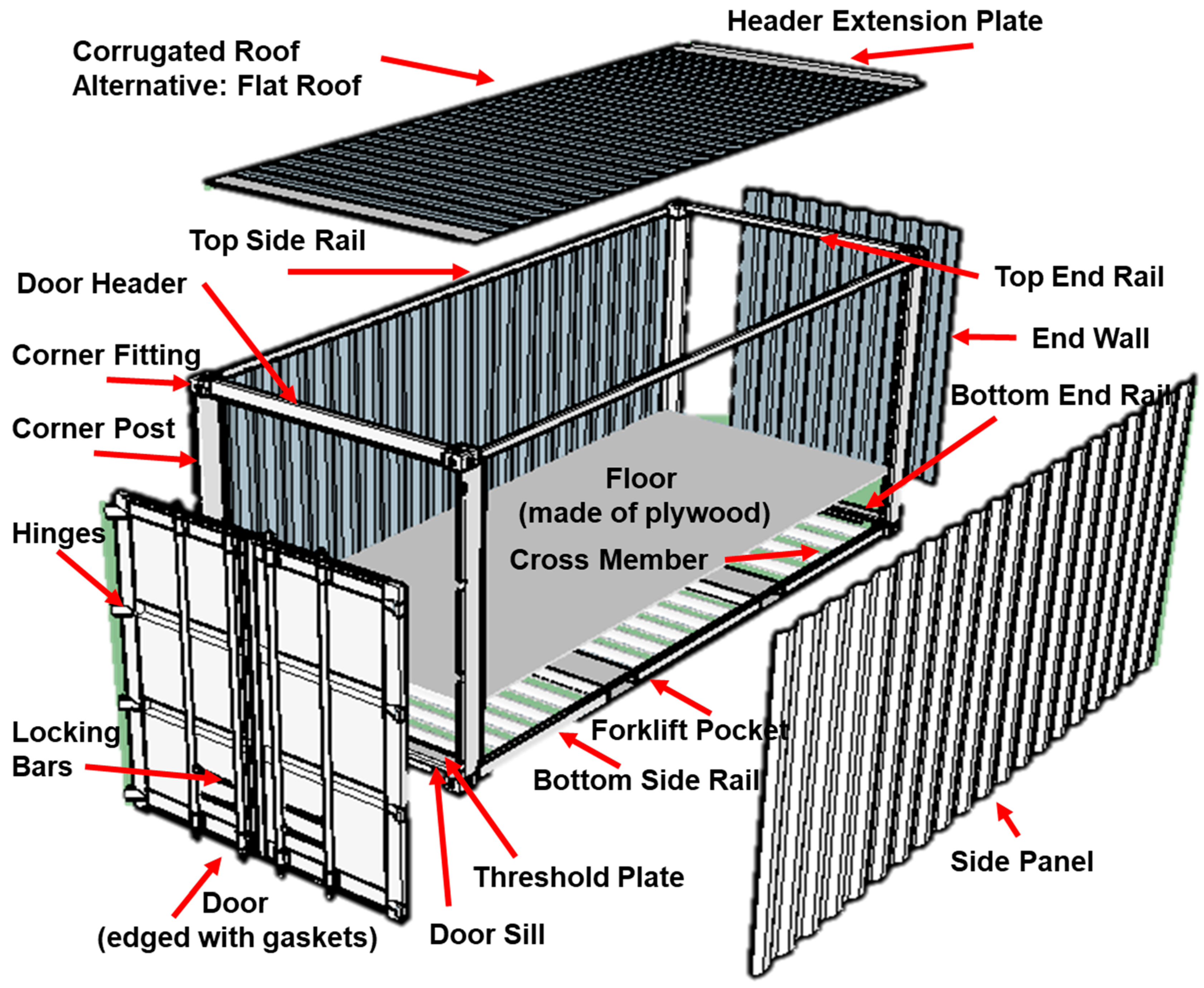
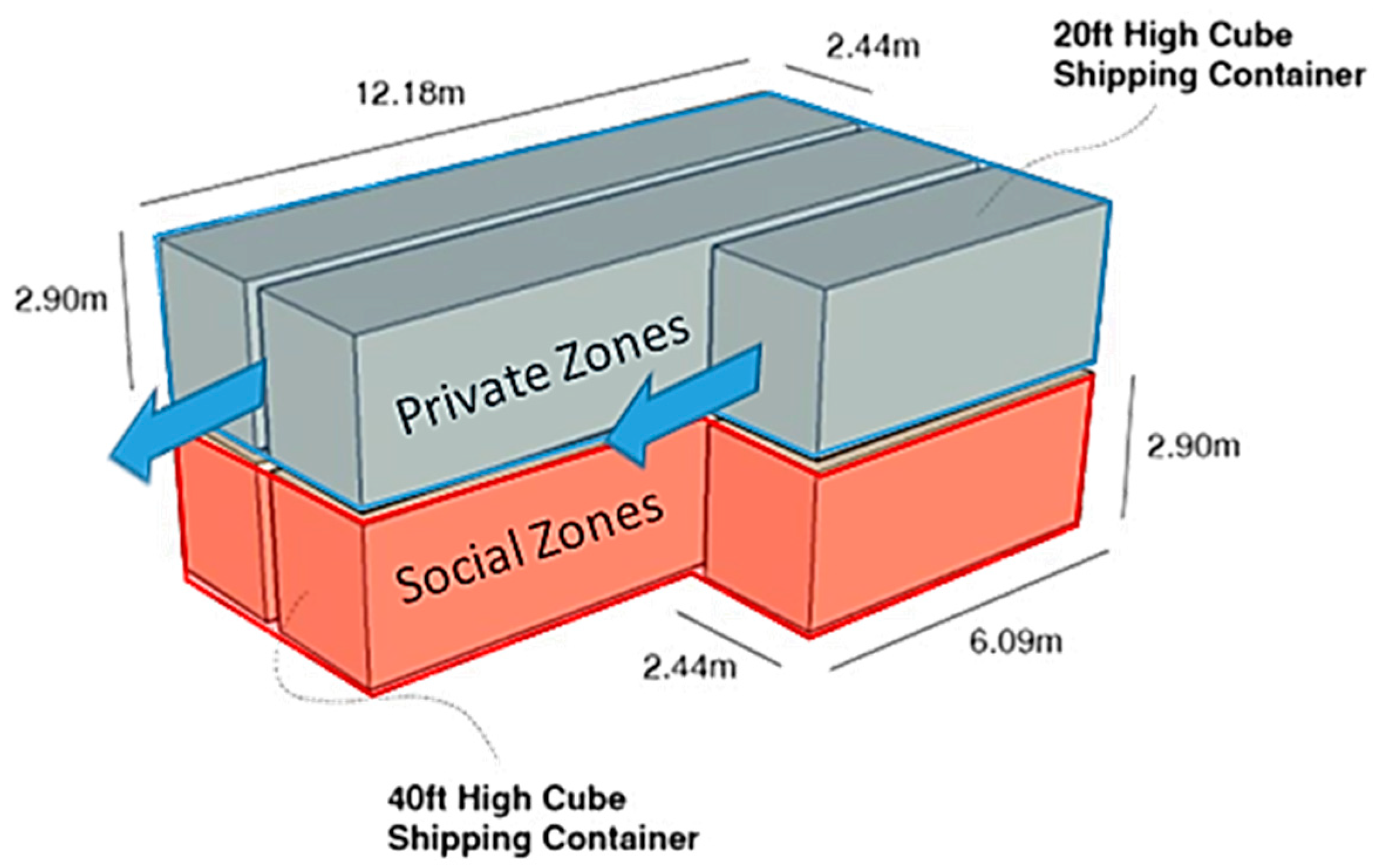
2.1. Shipping Container Standards

Almost all containers used globally comply with two main shipping container standards developed by the International Organization for Standardization (ISO) and the International Convention for Safe Containers (CSC), respectively. These documents dictate shipping containers’ specifications, structural strengths, serviceability, and applications. CSC standards [10] and ISO container standards 668 [11], 830 [12], 6346 [13], 1496-1 [14], 1161 [15], 2308 [16], and 3874 [17] encompass every specification for shipping containers including structural limits. However, there are no ISO standards which specify the framework conditions for the use of containers as building materials. After the end of their usage as cargo transport, containers used in construction are termed as ISBI—Intermodal Steel Building Units [8]. Then, the Safe Use Compliance of Containers provides guidance of both codes and regulations going forward for the modified shipping container through four industry segments [18].

2.2. Container Building Typology

The container architecture is increasing accepted with a great variety of applications, from simple emergency temporary housing to multifunctional, complex layout of various building types. Generally, there are six common types, as below:
  • Post-disaster or emergency settlements such as the Ex Container Project, anywhere, Japan [19] and Community Flowers, Chengdu, China [20]. These containers meet the requirements for emergency response characterized by prefabricated, easy transportation, lower overall cost, and rapid construction process. They especially provide great possibility for the victims as a safe asylum and a temporary settlement point for a longer term.
  • Residential buildings such as the Caterpillar house in Los Trapenses, Lo Barnechea, Santiago De [21] and The Container Guest House in San Antonio, USA [8]. Being similar to the first type, the standard container offers excessive feasibility for large-scale residential purpose in a shorter time. Furthermore, the size of the ISO shipping container satisfies the basic requirements of space, structural safety, lighting, and ventilation. Depending on the design condition and investment, it varies from the low-income apartment to luxury vocational villa.
  • Leisure and education premises, such as APAP (Anyang Public Art Project) Open School, Anyang, Korea [22] and the Nomadic museum, Tokyo, Japan [23]. Owing to the advanced level of industrial assembly, it is possible to manufacture the majority of interior decorations in the factory and then assemble the remaining part on site. This will allow settling containers for leisure purposes to special places, such as archipelagos and nature reserve areas, by reducing the influence on the local environment. Another possibility would be as a potential solution of nurseries or primary schools, providing a high-quality learning environment at low prices for suburbs or for under-resourced occasions [24].
  • Office premises, such as Sugoroku Office, Gifu, Japan [19]. Most of time, the development of new construction requires huge temporary offices. This kind of construction property is applicable to containers. Both environmental protection measures and low construction cost enable high-quality offices.
  • Commercial premises, such as Marketing shopping place in Puma, Spain [25]. Container transformation into commercial buildings has been widely found in newspaper kiosks, commissaries, coffee shops, fast food kiosks, showrooms, and small shops [6].
  • Others, such as Container Observatory, Incheon Songdao New City, South Korea [21]. Container buildings can serve as urban facilities, such as public toilets, telephone booths, or the expansion and construction components of buildings. Moreover, in places, such as National border defense line, scientific research bases, where there is less population and it is difficult to live, container architectural form is the best choice due to its low construction time and cost [6].

2.3. Container Building Construction Elements

Container materials roughly consist of steel, aluminum, stainless steel, and fiberglass. Both walls and ceiling of a ship container consist of corrugated metal sheets 2 mm thick, in which each element is made of “corten” steel. The only exception is the floor, made of plywood. As transportations units, containers are well processed in terms of rust, fire, and mildew resistance and once warned out, they could be used for at least another five to ten years. As an example, according to the data reported by Alejo Andrés and Palma Olivares, every time a 20 inch standard container is used, the carbon dioxide emissions can be cut by 12 tons over the life cycle with respect to concrete buildings [26].
The majority of shipping containers are in standardized dimensions. Table 1 presents the basic container parameters, such as dimensions (width, length, and height), floor areas, and weight [5]. The standardized dimension makes it an ideal building component for modular and prefabricated construction projects [5]. The most popular containers used as building components are 2.438 m in width and 6.096 m or 12.192 m in length. In many national regulations, there is a minimum height limitation of 2.4 m for residential buildings. Thereby, in this context, the residential building design only consider the high cube container with total height of 2.9 m to comply with the minimum clear ceiling height building requirement. Meanwhile, the containers’ internal dimensions differ from the external ones. In fact, internal walls have a plurality of corrugations, each one 25 mm depth. This narrows the container inner width by 50 mm due to both a concave and a convex corrugation. The backside, the other side without the door, is corrugated too. The doors have a thickness of 50 mm, which results in a total loss of 75 mm in length. The height of the inner dimension is less compared with the outer dimension. Depending on the floor type, this reduction, consisting of floor clearance and thickness, is approximately 177 mm. Since roof material is also corrugated, the internal height is reduced by slightly more than 200 mm in total [5,26].

2.3.1. Container Building Structure

The container structure is consisted of (a) bottom structure; (b) front end frame structure; (c) backend frame structure; (d) side wall, and (f) box top structure, as illustrated in Figure 1.

2.3.2. Container Building Foundations

The three most common foundations of container house are speared footing, mat foundation, and piles. Speared footing consists of reinforced concrete blocks or cylinders, which are located under the corner post of the container. In general, speared footings are especially suitable for small- to medium-sized buildings on strong or medium-strong ground. When the ground is too weak and unsafe, or the groundwater level is above the foundation, mat foundation can be used [8]. Another option is the use of piles (long beams of concrete, metal, and wood) that run deep into the ground. Obviously, this method is more expensive and only used when the top layer of the ground is too weak to support the load of the building [27]. Through the columns, the load can transfer to deeper load-bearing ground layers. For this reason, speared footings and mat foundations are more common under container houses.

2.3.3. Container Building Connections

When stacking on the foundations, all the containers need to be connected to each other or fixed to the foundation. Now, owing to a lack of standards, the connection method must be developed individually according to each project. Roughly, the connection has two ways: one is the permanent welding connection, while the other one is the temporary joint anchor bolt connection.
For connection to the foundation, the container is usually welded to an additional steel base plate. The latter is characterized by reinforcing bars on the underside that are generally inserted into the wet concrete foundations. After hardening of the concrete, the steel base mat first and the container afterwards are anchored to the foundations [8]. For connection with other containers, there are normally two methods. Temporary anchor bolt connections are generally composed of holes in the lower and upper corners, which can be locked together. In this way, twist and latch locks are the two main possibilities to fix the containers during the stacking. These connections can take the horizontal and vertical loads from the shipping operations. For housing constructions, this joint can be sufficient depending on their use. Particularly with unusual stacking constructions, it is suggested to design other adaptations for the joints.

3. Design Conditions and Methods for Thermal Comfort Assessment

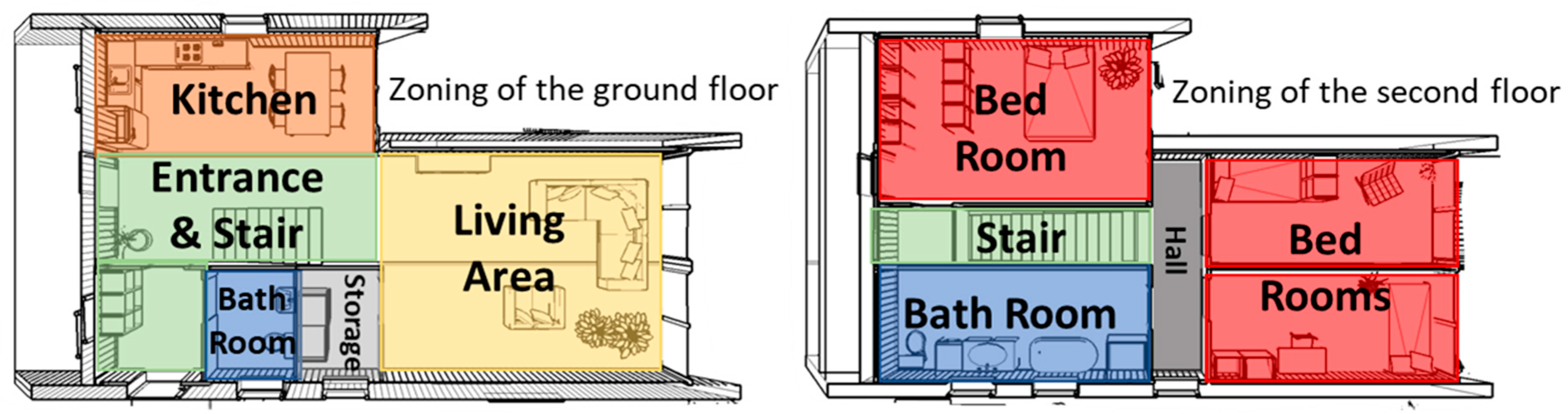
3.1. Basic Conditions for Design

The aim of this study is to explore three carbon-smart and thermally comfortable container houses designs in three different locations towards future climate scenarios. In order to fulfil this goal in a logical way, the paper thematically consists of three main parts.
  • First part: it starts with the elaboration of principles for processing containers as building materials;
  • Second part: it consists of a detailed climate analysis of three different locations. Afterwards, it prepares all the information for the preliminary planning and conceptual design presentation;
  • Third area: it further explores a future climate-adaptive building design container by employing the available low-carbon technology and best practices of construction. This part aims to inspire the container designers for more versatile building functions under future climate scenarios.
At the preliminary (early design) stage, this paper mainly focuses on the conceptual design. Rather than proposing three completely different buildings per climatic zone, this study firstly works with a generic model as a base case, and then modifies it according to three different design scenarios in cold (Stockholm), temperate (Berlin), and hot–humid (Rome) climatic zones, respectively. The generic model acts as a detached house for a four-member household. Accordingly, all three designs variants rely on the same basic concept, but are adapted to the climatic conditions for the individual climate zones, in order to guarantee a carbon-smart solution architecture for each building.
In principle, the container building form relates to shape, volume, mass, and configuration of a building along with the occupancy type and the users activities. Different from the conventional building form that may often be determined based on a number of concerns, selecting the proper form is one of the most important steps in a climate-resilient container building design considering energy efficiency, sustainability, investment cost, structure stability, and construction feasibility.
The proposed generic model consists of four 40 ft High Cube Shipping Containers and two 20 ft High Cube Shipping Containers, as shown in Figure 2. The proposed container design arrangement is supposed to mitigate the external climate, and provide comfortable interior conditions, thereby reducing cooling, heating, ventilation, and electrical lighting requirements. In terms of floor plan layout in Figure 3, the whole container configuration consists of two floors with several stacked containers. It presents a relatively compact floor plan, in order to create a smooth moving line and a functional space arrangement for the inhabitant. This layout enables a clear function organization: the main cores are the living space and bedrooms, surrounded by a serving space. The central placement of service core has an “inertia” against temperature fluctuations to store winter solar gain and summer night cooling from the perimeter. A derivative larger core is possible through opening the south-facing glazing on the ground floor, making connection between interior and exterior. Windows are placed around envelops to allow diffused light into the building, maximizing desirable sun penetration into living areas. Meanwhile, the floor plans in three different locations, a total flooring area of 148.6 m2, incorporate a variety of climate-adaptive design measures.
Regarding container building envelopes, the basic requirements are set with the U-values from the European Insulation Manufacturers Association’s report [28]. The scope of this paper is to propose the low U-value envelopes for container buildings, from the concept of view, in response to future climate [29]. In order to meet the generic container building design through the three different locations, each external part of the envelope with the minimum U-values has been proposed and estimated according to ISO 10456 [30], ISO 6946 [31], and manufacturing components [32,33], which are shown from Figure 4, Figure 5 and Figure 6. It can be found that the envelope design is one of the most effective strategies to increase interior insulation. Specifically, Vacuum Insulation Panels (VIP) have been used [32], providing higher thermal resistance and inner space saving with respect to conventional insulation materials. Moreover, the additional use of wood strip and wooden frame can take full advantage of the limited space on the container wall bases, offer adequate protection of vacuum insulation panels, and work as the fixed framework for interior wall panels’ installation.

3.2. Methodology for Thermal Comfort Assessment

In this section, the thermal comfort for the residential building has been assessed in Berlin (Germany), Stockholm (Sweden), and Rome (Italy), respectively. There are several reasons to choose the thermal comfort assessment. Firstly, thermal comfort is one of the major concern in living in a container building. Secondly, the indoor climate in the residential building is imperative in both psychological and physical aspects, where it could affect morale of the inhabitants, but also in its energy consumption holistically and the choices made about both envelope and structure. From another point of view, this method offers an intuitive and efficient initial assessment with graphic representations of hourly climate data compared with the time-consuming building modeling. Thermal comfort assessment is expected to help decision makers to visualize the unique overall patterns and subtle details in adaptive building design measures, characterizing different climate data during a preliminary building design or renovation process.

3.2.1. Investigated Climate Datasets

With the research purposes of building performance investigation under both historical and future climate conditions, the available hourly dependent climate dataset is necessary for a dynamic simulation. The method here has the baseline, which is the typical climate data ASHRAE IWEC from 1982 to 1997 with the “.epw” format (climate file from EnergyPlus website) [34]. After that, the “CCWorldWeatherGen” tool, developed by Energy and Climate Change Division, by University of Southampton, UK, is used. The tool is used to process the “present-day” climate files of the baseline data prepared for the future climate morphing in the next stage [35]. The morphed climate data is under HadCM3 predictions for a “medium–high” emissions scenario (A2) for 2020s, 2050s, and 2080s.

3.2.2. Thermal Comfort Model

The climate analysis is critical in exploring climate-adaptive potential, being an evitable part of climate-adaptive building design procedure. During the preliminary design stage, it enables a series of building design solutions that are especially devoted to human thermal comfort and energy-efficient measures. Usually, the thermal comfort characteristics are denoted with six indicators, which are air temperature, mean radiant temperature, relative humidity, air velocity in the area of environmental factors, clothing insulation, and metabolic heat in the area of personal factors [36]. In order to take full advantage of a building’s climate-adaptive potential, thermal comfort models represent the right guide for inhabitants to figure out the dependency of indoor thermal comfort to the external climate conditions and variability. In this study, all the climate analyses are based on one of the most popular comfort models, ASHRAE (American Society of Heating, Refrigerating and Air-Conditioning Engineers) Standard 55 and Current Handbook of Fundamentals Comfort Model. It is well known for the predicted mean vote (PMV) index and consists of two comfort zones, one for summer clothing and the other for winter. For the purpose of residential building design, it assumes that people can adapt clothing to match the season and feel comfortable in high air velocities having a wider comfort range than in building with centralized HVAC (Heating Ventilation and Air conditioning) systems [37]. With the aim of translating outdoor conditions to the same indoor comfort evaluation in three locations, the study employs some common generic criteria for the thermal comfort assessment under ASHRAE Standard 55, which are shown in Table 2.

3.2.3. Investigated Criteria for Each Zone

A total of 14 climate-adaptive design strategy zones, each of which is counted as the percentage of annual hours, were calculated based on the criteria mentioned in Table 2.
Zone 1—comfort relies on the assumption including the number of hours when the occupants of a space are thermally comfortable both in indoor or outdoor conditions. Within ASHRAE standard 55, it refers to only temperatures and humidity, calculated by PMV model.
Zone 2—both the outdoor Dry Bulb Temperature and the Minimum Total Horizontal Radiation determine the Sun Shading strategy, above which all windows should be shaded. Single-family dwellings with less internal loads, such as heat from occupants and equipment, usually have the Comfort Low boundary of 23.8 °C. According to different climate features in each location, the Minimum Global Horizontal Radiation varies. Within this case study, the value for Rome location (Italy) was set equal to 157.7 Wh/m2, while for Berlin (Germany) and Stockholm (Sweden) it was set equal to 630.9 Wh/m2. However this strategy only impacts on the desirable sun shading conditions, not directly affect the indoor comfort in building, these hours are not countable to the total number of indoor comfort hours.
Zones 3 and 4—the thermal storage, time lag, and damping effects of the mass in both summer and winter seasons all are relevant to these two High Thermal Mass Strategies. The top and bottom boundaries are constrained by the Dew Point temperature that limits at the top and bottom of the Comfort zone. The reason is that it tries to avoid the possibility of precipitation on high-mass surfaces under humid conditions. These strategies are effective when either natural ventilation or a ceiling fan is chosen on the conditions that the nighttime cool air is available and openings are closed during the hottest daytime hours. Zones 3 and 4 can work together with Zones 10 and 11, which describe the Passive Solar Direct Gain (winter sun) reaching the interior.
Zones 5 and 6—Evaporative Cooling takes place based on the principle that the liquid status of water changes into a gas status, taking on the latent heat of fusion and determining a cooler but more humid air. This enables the passive evaporative cooling to be a good cooling strategy in hot, dry climates. It shares the same rules as those for the Two-Stage Evaporative Cooling Zone, except that the slope of the upper boundary rises in proportion to the percentage efficiency of the Indirect Phase. The first stage takes advantage of evaporation to cool the outside of a heat exchanger. The next stage, the incoming air, which is from the first stage, would be cooled by direct evaporation.
Zones 7 and 8—Natural Ventilation Cooling is desirable in single-family dwellings. Through increasing the rate of sweat evaporation and giving the psychological sense of cooling, the inhabitant would have a passive cooling effect on the human body. Considering the natural ventilation strategy is a complex process, the following assumptions were made. For instance, the authors restrain the target location in urban, suburban, and wooded areas with the Terrain Category 2, instead of the meteorological wind speed, typically measured at height around 10 m. Accordingly, the given local wind speed can be calculated using Equation (1)
U H = U m e t ( δ m e t H m e t ) α m e t ( H δ ) α
where Umet, αmet and δmet is respective the meteorological wind speed, meteorological exponent value and meteorological layer thickness at the terrain category of 2, in which α and δ values can be found in Table 3. UH is the local wind speed at the top of the wall.
In addition, the target room is assumed with an interior design that includes adequate cross or stack ventilations through openings, so that they are able to utilize lower wind speeds or to reduce the higher one to comfortable indoor velocities. The effectiveness of this zone is further explained using a minimum indoor comfortable air velocity (usually at least 0.2 m/s) and a maximum indoor comfortable air velocity, above which people feel discomfort. In order to widen the comfort range, a wind speed equal to 1.50 m/s was chosen, corresponding to a Perceived Temperature Reduction of 3.7 °C [37]. Given the condition that people can control the air velocity in some way, they would be able to tolerate a wider comfort range. Accordingly, Zone 8 provides the analysis into the potential improvements from centralized ceiling or small local fans on a desk or table. However, the air conditioning is essential to reduce the humidity level and air temperature above this zone area.
Zone 9—Internal Heat Gain represents a rough estimation of the amount of heat that contribute to a building by internal loads, such as lights, people, and equipment. Here, the required Balance Point Temperature is the outdoor air temperature, at which internal loads alone will keep the building in the comfort zone. For this reason, well-designed and insulated buildings would have much lower balance point temperatures, and, therefore, consume much less heating energy. Typical residential buildings have relatively low internal loads and need more additional heating. Here, the Balance Point was set at 12.8 °C.
Zones 10 and 11—Passive Solar Direct Gain High/Low Mass provides an approximation at early design stage, because they strictly count on the detailed building design. In the definition of a low-mass zone, the authors assume that the shading system stops the direct solar gain once it is not desirable, avoiding overheating problems. As a result, it has a minimum beam radiation (or direct normal radiation) during a preceding hour. Taking an instance, the direct normal radiation of 158 Wh/m2 can produce a 5.56 °C temperature rise. The difference between high/low-mass zone is relevant to thermal time lag setting, which is typically on the order of 3 h for low-mass buildings and 12 h for high-mass buildings.
Zone 12—Wind Protection of Outdoor Spaces describes the total hours when cold or hot winds are uncomfortable in outdoor space. Due to this strategy not directly affecting the building indoor thermal comfort, these hours are not added to the total number of indoor comfort hours. However, some sort of windbreak would work effectively to prevent the occupied outdoor spaces or entry areas from cold wind penetration, drifting snow, or even frost bight in winter, as well as from hot, dry wind, drifting sand, windburn, or even heat stroke in summer.
Zones 13 and 14—Humidification and Dehumidification zones, Humidification lies directly below the comfort zone in the psychrometric chart. It represents the case in which the indoor air is within the dry bulb comfort temperature range but is too dry, therefore extra moisture should be supplemented. The dehumidification zone directly lies above the comfort zone in the psychrometric chart. On the contrary, it represents the opposite case to the humidification zone, in which the indoor air is within the dry bulb comfort range but is too humid, so, moisture should be removed. In reality, since enough moisture is often added to the air by inhabitant activities (expiration, perspiration, cooking, washing, bathing), dehumidification processes are common in modern well-sealed buildings.
Zones 15 and 16—Cooling Zone (and dehumidification if necessary)/Heating Zone (add humidification if necessary) both represent the cases in which the outdoor temperature is above the comfort range, and even does not belong to any other previous 14 climate-adaptive strategy zones. It then would by default be classified into the active cooling or heating zones, where a mechanical cooling or heating system is necessary to create a comfortable indoor environment. Despite the calculated hours falling into zones 13 and 14, it may take a few hours requiring either the cooling and humidification or the heating and dehumidification, which locate in zones 15 and 16.
Overall, under a total 16 zones (in which 14 are adaptive zones), some dots might meet the criteria for more than one strategy zone, representing more than one hour, the total hours might slightly exceed 8760 h.

4. Results and Analysis

4.1. Design Climatic Data

The preliminary container building design focuses on three different climate zones, as warm, temperate, and cold climate type. Therefore, each typical location has been selected with the aim to perform a climate-adaptive design optimization, minimizing the dependence on active systems at a subsequent stage.
Regarding Berlin, German, the climate file of Berlin/Schönefeld (Airport) (Latitude 52.38° N, Longitude 13.152° E) in Germany has been selected. According to the meteorological parameters recorded from 1982 to 1997, some conclusions can be made. The global horizontal solar radiation (Avg. Daily Total) varies from 405 to 5109 Wh/m2. The air temperature (Avg. Monthly) is in the range of 0 to 19 °C; while the relative humidity (Avg. Monthly) changes from 63% to 86%, and wind speed (Avg. Monthly) has the maximum and minimum value equal to 5 m/s and 3 m/s, respectively [34].
Regarding Stockholm, Sweden, the climate file of Stockholm Arlanda Airport (Latitude 59.62° N, Longitude 17.92° E) in Sweden has been selected. According to the meteorological parameters from 1982 to 1997, some conclusions can be made. The global horizontal solar radiation (Avg. Daily Total) varies from 199 to 5278 Wh/m2. The air temperature (Avg. Monthly) is in the range of −3 to 17 °C; while the relative humidity (Avg. Monthly) changes from 63% to 90%, and wind speed (Avg. Monthly) has the maximum and minimum value of 4 m/s and 2 m/s respectively [34].
Regarding Rome, Italy, the climate file of Roma Urbe (Latitude 41.95° N, Longtitude 12.50° E) in Italy has been selected. According to the meteorological parameters from 1982 to 1997, some conclusions can be made. The global horizontal solar radiation (Avg. Daily Total) varies from 1476 to 6804 Wh/m2. The air temperature (Avg. Monthly) is in the range of 8 to 24 °C; while the relative humidity (Avg. Monthly) changes from 73% to 81%, and wind speed (Avg. Monthly) has the maximum and minimum value of 4 m/s and 2 m/s, respectively [34].

4.2. Future Climate-Adaptive Prediction

Table 4 shows the results of climate-adaptive design assessment for the three target locations using both the historical and the future projected climate data. In terms of historical climate dataset, it points out the suitable climate-adaptive design measures for each location, as highlighted in Table 4. Different design strategies, between high and low mass, are only found between zone 10 and 11. By this way, it fits well into a generic model that shares the majority of common climate-adaptive features in a base case design. In terms of future climate scenarios, because all the baseline climate data were from 1982 to 1997 that was 22 years ago, it would be better to start from the projected climate data of 2020. Meanwhile, the container building is usually designed with a service year of 50, thereby the projected climate data of 2080 can be treat as an ultimate climate condition for current container building design.
In Rome, it would gradually face more failures in conventional climate-adaptive design measures in the coming 60 years. However, the share of total hours for air conditioning (considering both active heating and humidification and active cooling and dehumidification) would remain the similar percentage (58%) as the historical climate data showed. In another way, the percentage of time without active air conditioning would stay on around 42%. This means that it is vitally important to take climate-adaptive design measures into account to further improve the thermal comfort level during the remaining 36% annual hours. Among them, the appropriate utilization of internal heat gains seems to be most promising measure to invest, followed by the measure of sun shading of windows, then the passive solar direct gain using low mass.
Calculations show different results in Berlin and Stockholm. The cooling and dehumidification demands would rise up subtly, meanwhile the heating and humidification demands would decrease slightly. This means that both Berlin and Stockholm would enjoy the increase of the yearly comfort hours around 4% and 6%, respectively. Even though the overall climate signal presents a benefit in term of increased comfort hours, special attention should be paid to the occasional overheating risk for a container building. In fact, a container has the characteristics of air tightness, limited room height, and lightweight construction material, which poses a challenge to relieve environmental stress exclusively by natural ventilation and passive heating.

4.3. Proposed Generic Design Strategies

In line with the generic container building design, the next step is to create an efficient building shape along with the understanding of local climate conditions. It is well known that an efficient shape should have low surface/volume ratio for dominated heating locations so as to enclose the maximum amount of space with the minimum skin exposure in order to obtain a better energy performance. Together with the optimal overhang design, individual dimension of overhangs were calculated, shown in Table 5, by using the highest solar angles together with the fixed floor-to-ceiling window on southern facade. The bottom containers would have self-overhang through outward shifting of the upper containers, while the extending roofs work as overhangs for the upper ones. Hereafter, the relevant surface/volume ratio can be obtained from 0.90 to 0.93, presenting an optimal value for each location, which determines a balanced heat transmission through envelopes from cool winter to warm summer.
Accompanied by using existing structures of a shipping container, the container building also exhibits great potentials with solar energy. Both the stable performance and the silent operation are beneficial for a container building with different functions. Through building integration, it can help to realize an energy-efficient operated module. Table 6 shows the optimal photovoltaic (PV) dimension positions for each location, and the annual electricity consumptions amount are calculated according to the national energy statistics [38]. Based on this, the installed PV peak powers on roof have been evaluated, resulting in 14.82 kWp, 10.15 kWp, and 7.78 kWp for Stockholm, Berlin, and Rome, respectively, achieving the goal of energy-efficient container building design. In addition, another type of PV implementation was taken into account via the method of east/west vertical facade integration. Equipped with a vertical façade of 60 m2 per time, all the locations seem to be adequate to realize the goal of energy surplus, presenting a potential on-site renewable energy strategy.
Figure 7, Figure 8 and Figure 9 conceptually propose a general container building design for three individual locations. They take respect of both individual climate-adaptive measures and traditional building features. Based on the future climate trends pointed out in the previous section, it can be stated that the recommended promising measures are the appropriate utilization of the internal gains and the passive solar direct gain by using low mass in Rome and the prevention of the occasional overheating risk in both Stockholm and Berlin.
Therefore, the schematic drawings from Figure 4 to Figure 6 recommend an advanced building thermal management material. Unlike conventional sensible thermal storage material, Phase Change Materials (PCMs) provide much higher energy storage density, and the energy is stored and released at an almost constant temperature. These features are making them more and more attractive within the container building sector [39,40]. Specifically, when applied in the building container, both passive and active space cooling/heating purposes can employ PCMs. The first one means that PCMs are in containment, thermally separated from the building (e.g., hot and cold stores). The second one means that PCMs are applicable in the container building envelope (e.g., wallboards, roofs and floors), storing and releasing the energy when the indoor or outdoor temperatures are higher or lower the melting point [41]. For cooling requirements (during summer nights), manually controlled opening can draw the cold air inside, which is stored and supplied to the internal environment during the following day, when the cooling load increases. For heating requirements, PCMs can absorb and store the internal or direct solar heat gain, releasing it when the ambient temperature drops during the nighttime. This represents an opportunity for a container building to reduce the environmental stress partly by using natural ventilation and passive cooling/heating measures.

4.4. Comparison of the Proposed Design Strategies against the Conventional Designs

In contrast to the conventional designs, the proposed container building designs must consider the future climate impacts (such as temperature rise and humidity), and energy transition influence (such as PV deployment and energy sharing/storage). In order to maximize the passive potentials in future climate conditions, the specific container building designs are recommended to (1) develop an efficient geometry with low surface/volume ratio in order to minimize envelope exposure; the optimal surface/volume ratio can vary from 0.90 to 0.93, in the three locations; (2) maximize the capacity of PV panels to create a positive energy building, which can share energy to neighbor buildings when there is excess energy; (3) use the internal gains and the passive solar direct gain in Rome, but prevent the occasional overheating risk in both Stockholm and Berlin; (4) reduce the environmental impact and store extra energy by using PCM, in addition to natural ventilation and passive cooling/heating measures.
In addition, more generic strategies for the future design challenges can be summarized as:
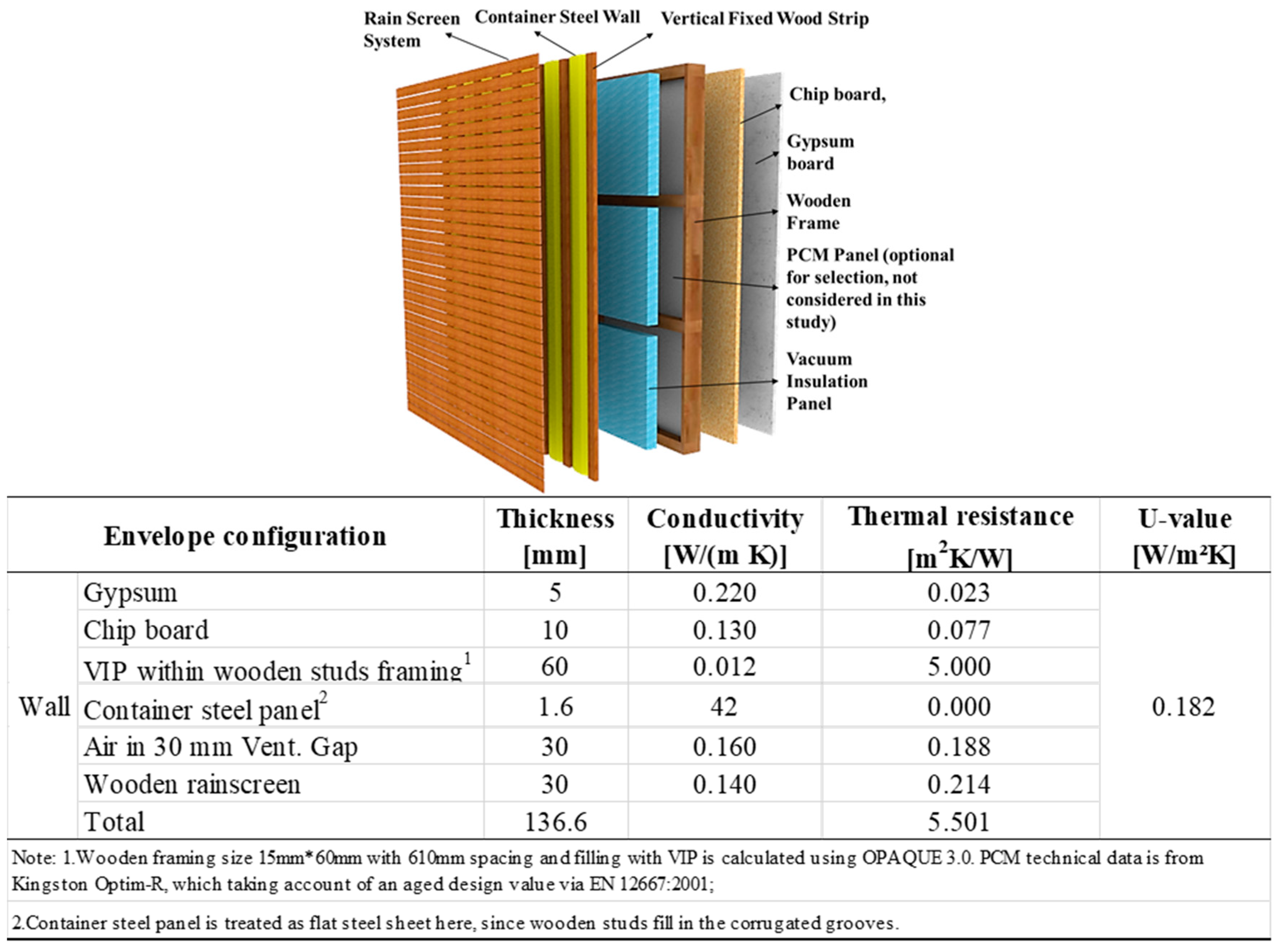
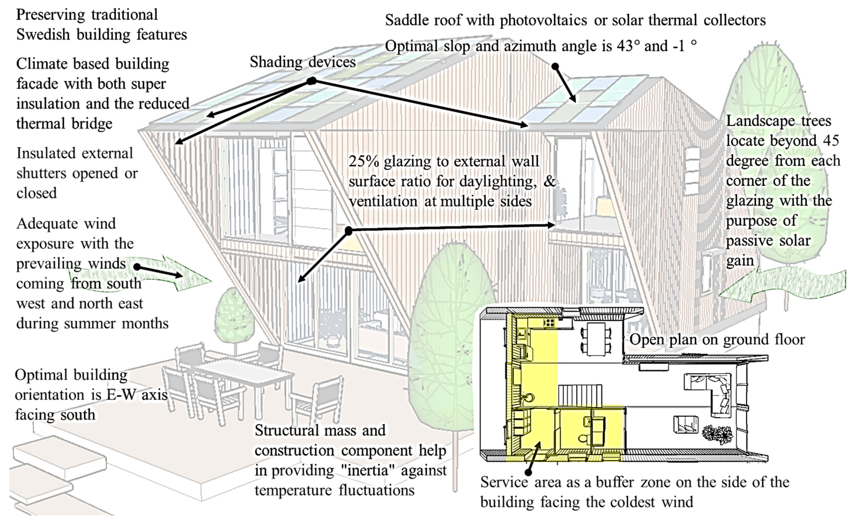
  • In Stockholm, climate-based building façade should be highlighted with both super thermal insulation and the reduced thermal bridge. The external shutters should be well insulated too. Window openings shall be remained towards the prevailing wind during the summer. The optimal building orientation is necessary to be east–west axis by facing south. Structural mass needs to be implemented to reduce the indoor temperature fluctuation. Service area could act as a buffer zone, facing the coldest direction. Landscape trees should be beyond 45 degree from each corner of the glazing with the purpose of maximum passive solar gains.
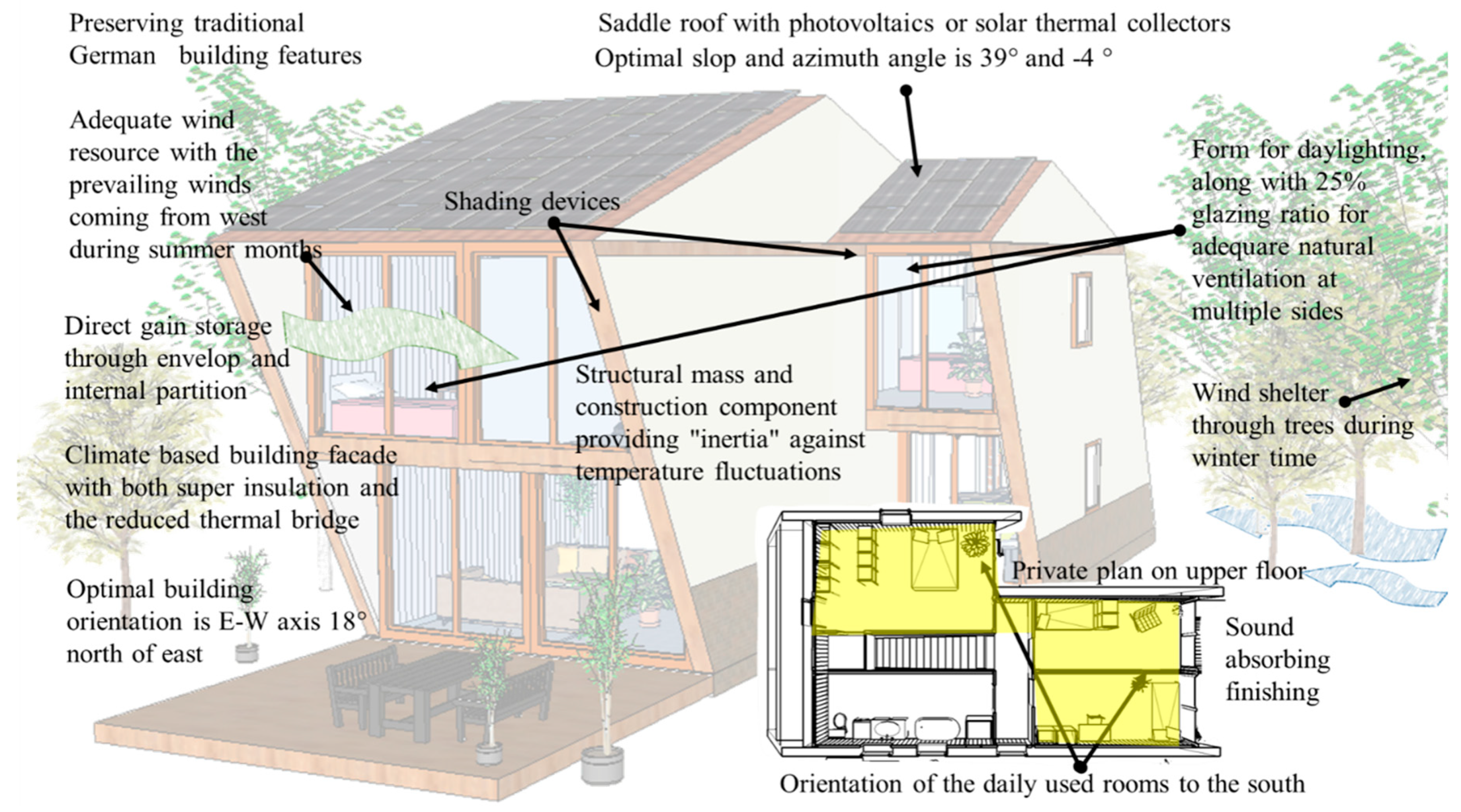
  • In Berlin, direct gain through the envelope and internal partition should be maximized. The optimal building orientation is east–west axis at 18 degree of northeast. The daily used rooms needs to face south. Surrounding trees can become wind shelter during winter. Other design features in natural ventilation, structural mass, and façade insulation are similar as that in Stockholm.
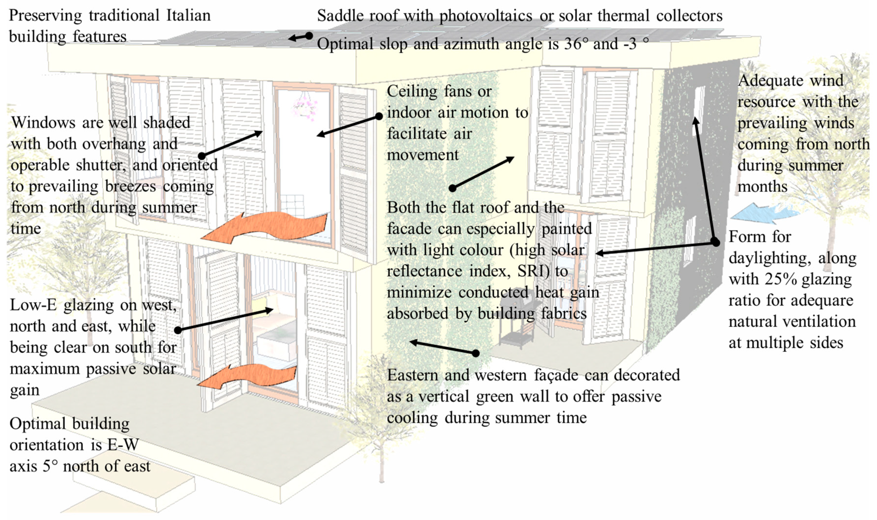
  • In Rome, high-performance windows must be well shaded with both overhang and operable shutter, facing prevailing wind direction. The optimal building orientation is east–west axis at 5 degree of northeast. Roof and façade can be painted with light color for the purpose of more heat refection in summer time. East and west façade can install vertical vegetation for both shading function and desirable microclimate adaption.

4.5. Potential Realization of the Designs

The proposed container building consists of four 40 ft High Cube Shipping Containers and two 20 ft High Cube Shipping Containers, as shown in Figure 2. Since 40 ft High Cube container provides 2.9 m ceiling height, this make it the main unit in this container building design project. The upper containers are dislocated slightly along the horizontal axis (blue arrows in Figure 2), so the basic building concept can be realized by simply re-assembling, without changing the main structure of containers. The wall system, from outside to inside, configures rain screen system as the external protection and decoration layer, container side wall, VIP layer, wood frame filed with PCM panels, wood chip board, and gypsum board. The windows are then achieved by tailoring their frames on the wall system. The roof, from outside to inside, consists of roof tile, wood frame filed with PCM panels, container corrugated roof layer, VIP layer, wooden strips, and gypsum ceiling. The floor has the concrete foundation, chip board, wooden frame, VIP layer, wooden floor, and coating layer, from outside to inside. All the containers can be connected to each other and fixed to the foundation by welding connection.
The design goal for a PCM integrated envelope is to produce a sort of extra thermal capacity to the lightweight walls, enhancing its overall efficiency. Overall, it has been found that there are two main ways to incorporate PCM into the container building envelope: as microencapsulation inside the construction materials (wallboards, concrete block, gypsum impregnation) or as macroencapsulation, which comprises the PCM inclusion in a form of package such as tubes, metal panels, spheres, and so forth. Specifically, microencapsulation means that the PCM is enclosed in a thin and resilient polymer shell (ranging from one µm to 1000 µm), where it can change its phase from solid to liquid and vice versa. This characteristic prevents leakage of PCM and an increased high-heat-conduction value can be achieved. For these reasons, microencapsulation allows the phase-change materials to be incorporated simply and economically into the container construction materials. On the other hand, macroencapsulation means filling the PCM in a macroscopic container. Macroencapsulation provides a large flexibility for design and is easier to manufacture for a commercial use. However, there are still some disadvantages deriving by the PCMs installation. Peippo et al. [44] evaluated that using PCM impregnated into the wallboards of a house can result in up to 15% reduction in energy costs annually, but due to the high installation costs, the residential building will need a service life of at least 25 years to make it viable. Finally, another issue is related to the PCM cycles degradation over time, requiring additional maintenance costs.
The design goal for a PV integrated container is to produce all the energy needed year round. It is well known that PV modules can be simply added or integrated to a container. In the first case, it means that the PV module is not directly related to the building structures’ functional aspects, while in second one, it influences the overall building energy performance, being a collaborative part of the design and having an architectural function. In this regard, as the main object of this study is to renovate existing shipping containers, to create an aesthetically attractive solution, the PV module integration techniques will be investigated. Among the research background, it has been found that PV modules can be integrated on roofs and façades. Specifically, PV roofs integration means exchanging parts of the existing roof with PV cells. In this case, PV modules can be spread over the entire roof, replacing all the covering parts, or can just cover parts of it, resulting integrated next to conventional roofing materials. Another way is to use foil products, which are lightweight and flexible, allowing easy installation and prevailing weight constraints for roofs. In this regard, the use of thin-film cells will allow maintaining the flexibility of the foil and PV efficiency due to the high temperature that can be reached when nonventilated roof solutions are used. Regarding the PV module integration on container building’s façade, PV modules can merely replace parts of the building envelope. In this case, the PV surface needs to be mechanical and thermal resistant. Finally, the integration of PV modules as external solar shading devices represents an effective way to control the thermal conditions of a building and internal daylight. Therefore, it can be concluded that integrating PVs could result in only a marginal extra cost to the overall renovation costs of a shipping container, due to their accessible costs and incentives available in many countries.

5. Future Works

The research scope of this paper focuses on the conceptual design issues of the upcycled container buildings. In a longer term, it involves more design issues at the following stages. In order to well upcycled a shipping container into a living building, Table 7 summarizes the holistic climate-adaptive container building design questions from aspects of design features, production/process, and challenges in implementation. Different roles, from designers, owners, stakeholders, and constructor, are recommended to seriously review these design questions on their way towards a sustainable container building module. So that the upcycled container architecture can comprehensively benefit from passive design measures, low cost operation and management, and versatile functions under the future climate scenarios. In addition, temperature-dependent material properties in different climates should be considered when simulating the energy performance. Further LCA case studies of the three container buildings will be conducted in the specific climates, due to dissimilar inventory data, system boundary, and assumptions in different climates.

6. Suggestion and Conclusions

This paper explores the future design challenges, helping the shipping container to be upcycled into a thermally comfortable and energy-efficient living module. The proposed conceptual design responds to new challenges with the feature of a future built environment that would be characterized by low energy use, low carbon footprint, higher average temperatures (even at night), increased average humidity level, and preparedness to future extreme weather events, such as heat waves, drought, and extra-tropical storms. The proposed design maximizes the integration of passive strategies, renewable/low-carbon technologies, and construction practices under different climatic scenarios.
In fact, the general reuse of the shipping container as a modular and prefabricated construction component in architecture enables it to be a sustainable building option with versatile applications, including post-disaster settlements, commercial use, military operations, and low-income housing. Owning to the logistics characteristics of air tightness, limited space height, and light weight, the overall performance of a repurposing container building is still doubtful, especially the indoor comfort level towards deteriorating climate change. Currently, appropriate indoor climate design has stricter requirements on both envelope and structure, which further impact on total energy consumption. Concerning this series of reasons, this paper offers an intuitive and efficient initial assessment with hourly climate data representations especially for the concept design stage, instead of running a labor-intensive building modeling.
By assessing the projected future climate data along with the ASHRAE Standard 55 and Current Handbook of Fundamentals Comfort Model, it indicates that Rome would gradually face more failures in conventional climate-adaptive design measures in the coming 60 years. Therefore, it is vital to re-examine the conventional energy-efficient design with respective to the thermal comfort level during the remaining 36% annual hours under a future scenario. The appropriate utilization of internal heat gains seems to be the most promising measure to explore, followed by the measure of windows sun shading and passive solar direct gain by using the low-mass construction material. While the future climate analyses show different results in Berlin and Stockholm. Special attention should be paid to the occasional overheating risk and more humidity issues. As for repurposing container buildings, it means higher demands in improving both thermal resistance and hygro-thermal capacity of the envelope. For instance, the weakness in air tightness performance can be improved by applying a closed insulation enhancement throughout the whole enclosure. Such processing meanwhile can assist in lowering thermal bridge.
The climate-adaptive design proposals are finally illustrated as warm, temperate, and cold climates, respectively, across the European area for a repurposed container building. Future work is discussed beyond the concept design. The results are expected to inspire designers or decision-makers with overall design patterns and subtle details towards a livable and durable living module design.

Author Contributions

J.S. works on investigation, adaptive analysis/design, and basic writing. B.C. is responsible for data curation; X.Z. and J.K. are response for writing, review & editing. S.K. and P.K. contribute to resources and funding acquisition. All authors have read and agreed to the published version of the manuscript.

Funding

The authors would like to acknowledge the financial support from the joint project of Sweden and Germany: ‘Product and process development for the preparing and realization of complete buildings of various types of use using energy-efficient, partially energy independent lightweight construction solutions, ENSECO’. The authors would also like to thank the financial support from European and Dalarna Regional Development Fund through the project ‘Energiinnovation’ in Sweden.

Acknowledgments

Moreover, special thanks are given to the graduated master student, Linda Reitz, from Department of Energy and Built Environments, Dalarna University, Falun, Sweden and Xinxin Guan, from College of Architecture and Urban Planning, Guangzhou University, Guangzhou, China for their container buildings design support, along with the Climate Consultant 6.0 that was developed by the UCLA Energy Design Tools Group.

Conflicts of Interest

The authors declare no conflict of interest

References

  1. Gharehgozli, H.A. Developing New Methods for Efficient Container Stacking. Ph.D. Thesis, Erasmus University, Rotterdam, The Netherlands, 27 November 2012. Available online: http://citeseerx.ist.psu.edu/viewdoc/download?doi=10.1.1.573.5069&rep=rep1&type=pdf (accessed on 16 October 2019).
  2. Kuzmicz, K.A.; Pesch, E. Approaches to empty container repositioning problems in the context of Eurasian intermodal transportation. Omega 2019, 85, 194–213. [Google Scholar] [CrossRef]
  3. Sharma, S. Maersk Line, What Happens When Containers Retire? Maersk Line. 7 February 2015. Available online: https://www.supplychaindigital.com/scm/what-happens-when-containers-retire (accessed on 7 August 2019).
  4. Dara, C.; Hachem-Vermette, C.; Assefa, G. Life cycle assessment and life cycle costing of container-based single-family housing in Canada: A case study. Build. Environ. 2019, 163, 106332. [Google Scholar] [CrossRef]
  5. Islam, H.; Zhang, G.; Setunge, S.; Bhuiyan, M.A. Life cycle assessment of shipping container home: A sustainable construction. Energy Build. 2016, 128, 673–685. [Google Scholar] [CrossRef]
  6. Olivares, P.; Andres, A. Sustainability in Prefabricated Architecture—A Comparative Life Cycle Analysis of Container Architecture for Residential Structures. Master Thesis, Victoria University of Wellington, Wellington, New Zealand, 2010; pp. 215–219. Available online: https://researcharchive.vuw.ac.nz/xmlui/handle/10063/1486 (accessed on 16 March 2019).
  7. Aktan, I. Reusing Shipping Contain: What Are the Advantages and Challenges? 9 October 2017. Available online: https://www.morethanshipping.com/reusing-shipping-containers-advantages-challenges/ (accessed on 16 March 2019).
  8. Giriunas, K.; Sezen, H.; Dupaix, R.B. Evaluation, modeling, and analysis of shipping container building structures. Eng. Struct. 2012, 43, 48–57. [Google Scholar] [CrossRef] [Green Version]
  9. Hong, Y. A study on the condition of temporary housing following disasters: Focus on container housing. Front. Archit. Res. 2017, 6, 374–383. [Google Scholar] [CrossRef]
  10. International Maritime Organization. International Convention for Safe Containers; International Maritime Organization: London, UK, 1996. [Google Scholar]
  11. International Organization for Standardization. ISO/TC 104. ISO 668:1995 Series 1 Freight Containers-Classification, Dimensions and Ratings; International Organization for Standardization: Geneva, Switzerland, 1995. [Google Scholar]
  12. International Organization for Standardization. ISO/TC 104. ISO 830:1999 Freight Containers-Vocabulary; International Organization for Standardization: Geneva, Switzerland, 1999. [Google Scholar]
  13. International Organization for Standardization. ISO/TC 104. ISO 6346:1995 Freight Containers Coding, Identification and Marking; International Organization for Standardization: Geneva, Switzerland, 1995. [Google Scholar]
  14. International Organization for Standardization. ISO/TC 104. ISO 1496-1:1990 Series 1 Freight Containers-Specification and Testing—Part 1: General Cargo Containers for General Purposes; International Organization for Standardization: Geneva, Switzerland, 1990. [Google Scholar]
  15. International Organization for Standardization. SO/TC 104. ISO 1161:1984/Cor 1:1990 Technical Corrigendum 1:1990 to ISO 1161:1984; International Organization for Standardization: Geneva, Switzerland, 1990. [Google Scholar]
  16. International Organization for Standardization. ISO/TC 104. ISO 2308:1972 Hooks for Lifting Freight Containers of up to 30 Tonnes Capacity-Basic Requirements; International Organization for Standardization: Geneva, Switzerland, 1972. [Google Scholar]
  17. International Organization for Standardization. ISO/TC 104. ISO 3874:1997 Series 1 Freight Containers Handling and Securing; International Organization for Standardization: Geneva, Switzerland, 1997. [Google Scholar]
  18. Modular Building Institute. USA, Safe Use and Compliance of Modified ISO Shipping Containers for Use as Buildings and Building Components; Modular Building Institute and National Portable Storage Association: Charlottesville, VA, USA, 2017. [Google Scholar]
  19. Ruting, Z. Case Analysis of Container Construction. Master Thesis, Xi’an University of Architecture and Technology, Xi’an, China, 2017. [Google Scholar]
  20. Hands On Chengdu Charity. Community Flowers. World Archit. Rev. 2009, 24, 84–87. [Google Scholar]
  21. Kaituo, L. The Application and Development of the Container Architecture in China. Master Thesis, Tianjin University, Tianjin, China, 2014. [Google Scholar]
  22. Zou, D.; Zhuonan, W.; Lei, W. Container Building Design; Fhoenix Scientific Publishing House: Nanjing, China, 2018. [Google Scholar]
  23. Broome, B. A traveling museum transports urban visitors. Architectural Record, May 2005; 109. [Google Scholar]
  24. ONTAINEX. Containers & Modules. Available online: http://www.containex.co.uk/en/products (accessed on 28 November 2019).
  25. Kotnil, J. New Container Architecture; Fhoenix Scientific Publishing House: Nanjing, China, 2013. [Google Scholar]
  26. Container Container. Shipping Container Dimensions, ContainerContainer, 2019. Available online: https://www.containercontainer.com/shipping-container-dimensions (accessed on 16 March 2019).
  27. Weinan, W. Studies on the Design Strategies of Contemporary Shipping Container Architecture. Ph.D. Thesis, South China University of Technology, Guangzhou, China, 2011. [Google Scholar]
  28. European insulation Manufacturers Association. U-Values for Better Energy Performance of Buildings. 2007. Available online: https://www.eurima.org/reports/u-values-for-better-energy-performance-of-buildings (accessed on 19 October 2019).
  29. Shen, J.; Copertaro, B.; Sangelantoni, L.; Zhang, X.; Suo, H.; Guan, X. An early-stage analysis of climate-adaptive designs for multi-family buildings under future climate scenario: Case studies in Rome, Italy and Stockholm, Sweden. J. Build. Eng. 2020, 27, 100972. [Google Scholar] [CrossRef]
  30. International Organization for Standardization. ISO 10456:2007, Building Materials and Products—Hygrothermal Properties—Tabulated Design Values and Procedures for Determining Declared and Design Thermal Values; International Organization for Standardization: Geneva, Switzerland, 2007. [Google Scholar]
  31. International Organization for Standardization. ISO 6946: 2018, Components—Thermal Resistance and Thermal Transmittance—Calculation Procedure Describes the Procedures for the Calculation of the Thermal transmiTtance (U-Value, Formerly K-Value) of Structures; International Organization for Standardization: Geneva, Switzerland, 2018. [Google Scholar]
  32. Kingspan VIP. Available online: http://www.kingspaninsulation.co.uk/optimr (accessed on 9 December 2018).
  33. Steinecker Container Handel, Technical Specification for Steel Dry Cargo Container. Available online: http://steinecker-container.de/container/Container2/Spez-Container/Spez_high%20cube20.pdf (accessed on 9 December 2018).
  34. National Centers for Environmental Information, Data Access. Available online: https://www.ncdc.noaa.gov/data-access (accessed on 15 March 2019).
  35. University of Southampton. CCWorldWeatherGen v 1.9; University of Southampton: Southampton, UK, 2017. [Google Scholar]
  36. American Society of Heating, Refrigerating, Thermal Environmental Conditions for Human Occupancy (ANSI/ASHRAE Standard 55-2010), 22 April 2011. Available online: http://arco-hvac.ir/wp-content/uploads/2015/11/ASHRAE-55-2010.pdf (accessed on 13 May 2019).
  37. American Society of Heating, Refrigerating. ASHRAE Fundamental 2017; ASHRAE: Atlanta, GA, USA, 2017. [Google Scholar]
  38. PVGIS Group, European Commission Joint Research Centre. Photovoltaic Geographical Information System, European Commission Joint Research Centre, 12 May 2017. Available online: https://re.jrc.ec.europa.eu/pvg_tools/en/tools.html (accessed on 14 October 2019).
  39. Copertaro, B.; Principi, P.; Fioretti, R. Thermal performance analysis of PCM in refrigerated container envelopes in the Italian context—Numerical modeling and validation. Appl. Therm. Eng. 2016, 102, 873–881. [Google Scholar] [CrossRef]
  40. Fioretti, R.; Principi, P.; Copertaro, B. A refrigerated container envelope with a PCM (Phase Change Material) layer: Experimental and theoretical investigation in a representative town in Central Italy. Energy Convers. Manag. 2016, 122, 131–141. [Google Scholar] [CrossRef]
  41. Pasupathy, A.; Velraj, R.; Seeniraj, R.V. Phase change material-based building architecture for thermal management in residential and commercial establishments. Renew. Sustain. Energy Rev. 2008, 12, 39–64. [Google Scholar] [CrossRef]
  42. Eurostat. Eurostat Database, Eurostat. Available online: https://ec.europa.eu/eurostat/tgm/table.do?tab=table&init=1&language=en&pcode=ten00117&plugin=1 (accessed on 30 July 2019).
  43. Tukiainen, M. GAISMA, Sunrise, Sunset, Dawn and Dusk Times around the World. Available online: https://www.gaisma.com/en/ (accessed on 14 October 2019).
  44. Peippo, K.; Kauranen, P.; Lund, P.D. A multicomponent PCM wall optimized for passive solar heating. Energy Build. 1991, 17, 259–270. [Google Scholar] [CrossRef]
Figure 1. Schematic diagram of a 20 ft standard shipping container.
Sustainability 12 00108 g001
Figure 2. Used Containers in the generic model.
Sustainability 12 00108 g002
Figure 3. Floor plan of the generic model.
Sustainability 12 00108 g003
Figure 4. Conceptual wall configuration with U-value estimation.
Sustainability 12 00108 g004
Figure 5. Conceptual roof configuration with U-value estimation.
Sustainability 12 00108 g005
Figure 6. Conceptual floor configuration with U-value estimation.
Sustainability 12 00108 g006
Figure 7. Generic design proposal for a single-family container building in Stockholm, Sweden.
Sustainability 12 00108 g007
Figure 8. Generic design proposal for a single-family container building in Berlin, Germany.
Sustainability 12 00108 g008
Figure 9. Generic design proposal for a single-family container building in Rome, Italy.
Sustainability 12 00108 g009
Table 1. Basic parameters of the most popular containers [1].
SizeWidth (m)Length (m)Height (m)Floor Area (m2)Volume (m3)Empty Weight (kg)
20 ft equivalent unit2.4386.0962.59114.8633.12200
20 ft high cube equivalent unit2.4386.0962.914.8643.092350
40 ft equivalent unit2.43812.1922.59129.7267.53800
40 ft high cube equivalent unit2.43812.1922.929.7286.193900
Table 2. Criteria assumed in ASHRAE Standard 55 [29].
Zone.VariantDefinitionCriteria Range
ValueUnit
1Comfort Zone
Winter Clothing Indoors1.0 Clo = long pants, sweater1Clo
Summer Clothing Indoors0.5 Clo = shorts, light tops0.5Clo
Activity Level Daytime1.1 Met = sitting, reading1.1Met
Predicted Percent of People calculated by PMV model100-PPD90
Comfort Lowest Winter Temp. calculated by PMV modelET*C20.3
Comfort Highest Winter Temp. calculated by PMV modelET*C24.3
Comfort Highest Summer Temp. calculated by PMV modelET*C26.7
Maximum Humidity calculated by PMV model 84.6
2Sun Shading Zone (defaults to Comfort Low)
Min. Dry Bulb Temperature when Need for Shading begins23.8°C
Min. Global Horiz. Radiation when Need for Shading beginsVariedWh/m2
3High Thermal Mass Zone
Max. Outdoor Temperature Difference above Comfort High8.3°C
Min. Nighttime Temperature Difference below Comfort High1.7°C
4High Thermal Mass with Night Flushing Zone
Max. Outdoor Temperature Difference above Comfort High16.7°C
Min. Nighttime Temperature Difference below Comfort High1.7°C
5Direct Evaporative Cooling Zone (defaults to Comfort Low)
Max. Wet Bulb set by Max. Comfort Zone Wet Bulb20°C
Min. Wet Bulb set by Min. Comfort Zone Wet Bulb6.6°C
6Two-Stage Evaporative Cooling Zone
Efficiency of Indirect Stage50%
7Natural Ventilation (Cooling/Adaptive Comfort) Zone (air velocity is controlled by opening)
Terrain Category to modify Wind Speed2 = suburban2
Min. Indoor Velocity to Effect Indoor Comfort0.2m/s
Max. Comfortable VelocityASHARE Std. 551.5m/s
8Fan Forced Ventilation Cooling Zone
Max. Mechanical Ventilation Velocity0.8m/s
Max. Perceived Temp. Reduction3°C
9Internal Heat Gain Zone (e.g., lights, people, equipment)
Balance Point Temp. below which heating is needed12.8°C
10Passive Solar Direct Gain High Mass Zone
Min. South Window Radiation for 5.56 °C Temp. rise158Wh/m2
Thermal Time Lag for High-Mass Building12h
11Passive Solar Direct Gain Low Mass Zone
Min. South Window Radiation for 5.56 °C Temp. rise158Wh/m2
Thermal Time Lag for High-Mass Building3h
12Wind Protection of Outdoor Spaces Zone
Velocity above which Wind Protection is desirable8.5m/s
Dry Bulb Temp. above or below Comfort Zone11.1°C
13Humidification Zone (defined by and below Comfort Zone)
14Dehumidification Zone (defined by and above Comfort Zone)
Note: PMV stands for predicted mean vote. ASHARE Std. stands for American Society of Heating, Refrigerating and Air-Conditioning Engineers Standard
Table 3. Atmospheric Boundary Layer Parameters [37].
Terrain CategoryDescriptionExponent, αLayer Thickness, δ (m)
1Large city centers, in which at least 50% of buildings are higher than 25 m, over a distance of at least 0.8 km or 10 times the height of the structure upwind, whichever is greater0.33460
2Urban and suburban areas, wooded areas, or other terrain with numerous closely spaced obstructions having the size of single-family dwellings or larger, over a distance of at least 460 m or 10 times the height of the structure upwind, whichever is greater0.22370
3Open terrain with scattered obstructions having heights generally less than 9 m, including flat open country typical of meteorological station surroundings0.14270
4Flat, unobstructed areas exposed to wind flowing over water for at least 1.6 km, over a distance of 460 m or 10 times the height of the structure inland, whichever is greater0.10210
Table 4. Climate-adaptive design strategies for three locations under climate scenario (unit: h).
Rome, ItalyBerlin, GermanyStockholm, Sweden
His.202020502080His.202020502080His.202020502080
Z 155052553260570383110731285392633919907
Z 210911256142815901101482042673771142215
Z 38679656014217820225813782126
Z 49797747614720625433413794162
Z 59488828613618620829913788197
Z 610210310210914119724033713792208
Z 78066647110211612120313592183
Z 85136384963708111913654115
Z 9284727932920286624332537246923061874205020021903
Z 10811759752708596487427345767661575437
Z 11571501441452720689707607853879886752
Z 1256472620360335295260135136123109
Z 13000000000000
Z 14171017001577128023102191291757244660
Z 154687911324206452584216009129
Z 16277725832085167650574803443640995839549450564666
Table 5. Calculation results of building form parameters.
Sustainability 12 00108 i001LocationStockholmBerlinRome
59.62° N, 17.92° E52.38° N, 13.15° E41.95° N, 12.50° E
α [°] Highest in Summer546172
β [°] Lowest in Winter71425
W [m] 2.59
R [m]1.881.440.84
Exposed Area [m2]27.5521.0212.32
Total standard exposed area, [m2]374.8
Total volume [m3]430.93
Surface to volume ratio 0.930.920.90
Table 6. Estimation of photovoltaics potentials for container building design.
LocationStockholmBerlinRome
59.62° N, 17.92° E52.38° N, 13.15° E41.95° N, 12.50° E
Annual electricity estimation [kWh] 127,90625,48721,991
Optimal slop angle [°] 2433936
Optimal Azimuth angle [°] 2−1−4−3
Installed peak PV power on roof [kWp] 314.8210.157.78
Full roof installation [kWh] 427,00029,80043,000
East façade installation [kWh] 526,70029,00040,400
West façade installation [kWh] 528,00030,70042,100
Note: 1 Estimation is made using the data from national residential building electricity statistics in 2015 [42]; 2 Optimal angles have been achieved through [38]; 3 The values are calculated for 100% offset ratio and 86% system losses factor for the photovoltaic. The perfect sun hours are 6 h for Stockholm, 8 h for Berlin, and 9 h for Rome through [43]; 4 Roof installed area is assumed with 30 m2; 5 East/west installed area is assumed with 60 m2.
Table 7. Holistic design questions towards a sustainable container building design.
Scope 1. Features of Container BuildingTemporary Building• Short term usage, movable;
• Non-construction;
Prefabricated Module• Quick construction speed;
• Controllable in both quality and price;
Repeated Utilization• Reuse of cargo container;
• Recycled construction unit;
• Movable building block;
Customized Appearance• Support bespoke design;
• Decoration from self-structure characteristics;
Scope 2. Production and ProcessConcept Design• Use or repurpose existing containers;
• Complying with the relevant/binding codes;
• Use recycled or carbon sequestered material;
• Specify higher grade options to resources usage;
• Design for durability under future climate change;
• Understand site and passive resources;
Schematic Design and Design Development• Massing comparison;
• Mechanical and plumbing system integration;
• Envelop reinforcement;
• Establish operational and embodied carbon performance targets;
Construction and Operation• Logistics information with all the assembly parts;
• Assembling and installation;
• Follow-up operation and maintenance;
Scope 3. Challenges in implementationConstruct Component Design• Prefabrication of components;
• General elements and customized elements;
• Integration and separation of construct components;
Construction In-Site• Prefabrication in manufacturers;
• Feasible dimensions for transportation and installation;
• Unified external construction to avoid thermal bridges leakages;
• Maintenance during remaining service time;
Commercialization• Marketing positioning;
• Cost and environmental impacts control;
• Standardization and Customization;
• Derivatives and updates of product;
• Follow-up operation and maintenance.

