Genetic Algorithm for Embodied Energy Optimisation of Steel-Concrete Composite Beams


1
WSP in the UK, WSP House, 70 Chancery Lane, London WC2A 1AF, UK
2
School of Civil Engineering, Faculty of Engineering and Physical Sciences, University of Leeds, Woodhouse Lane, Leeds LS2 9JT, UK
*
Author to whom correspondence should be addressed.
Sustainability 2020, 12(8), 3102; https://0-doi-org.brum.beds.ac.uk/10.3390/su12083102
Submission received: 27 January 2020
/
Revised: 31 March 2020
/
Accepted: 10 April 2020
/
Published: 13 April 2020
(This article belongs to the Special Issue Sustainable Innovative Solutions for Material Efficient Buildings)
Abstract
:The optimisation of structural performance is acknowledged as a means of obtaining sustainable structural designs. A minimisation of embodied energy of construction materials is a key component in the delivery of sustainable future designs. This study attempts to understand the relationship between embodied energy and structural form of composite floor plates for tall buildings, and how this form can be optimised to minimise embodied energy. As a search method based upon the principles of genetics and natural selection, genetic algorithms (GA) have previously been used as novel means of optimising composite beams and composite frames for cost and weight objective functions. Parametric design models have also been presented as optimisation tools to optimise steel floor plates for both cost and embodied carbon. In this study, a Matlab algorithm is presented incorporating MathWorks global optimisation toolbox GA and utilising Eurocode 4 design processes to optimise a composite beam for five separate objective functions: maximise span length; minimise beam cross-section; minimise slab depth; minimise weight; minimise deflected shape for each of the objective functions. Candidate designs are to be assessed for embodied energy to determine individual relationships. This study shows that it is possible to reduce the embodied energy of steel–concrete composite beams by genetic algorithm optimisation whilst remaining compliant to given design codes.
1. Introduction
Researchers are focusing on optimising the material efficiency of structures and structural systems [1,2,3,4,5] as well as on the performance of structures and buildings specifically to wind and seismic actions by minimising weight and control capacity [6,7,8,9,10,11], in order to avoid using redundant material, thus increasing the stiffness over weight ratio without compromising their capacity. However, the optimisation process can be time and resource intensive when it is done with traditional methods, thus in recent years advanced computational tools have been employed to carry out effective material distribution for structures, such as the shape and topology optimisation techniques [12,13,14,15], technologies previously used in aeronautical and automotive engineering where material savings is of ultimate importance for the performance of the shuttle and vehicles. More recently, another form of optimisation is employing large data sets, developed by advanced computational and parametric studies, which optimise the right combination of parameters through the large volume of data to be used in a structural system. A simple and reliable algorithm is the genetic algorithm (GA) [16] which has previously been used to optimise composite beams [17,18,19] and composite frames [20] for cost and weight objective functions. Parametric design models [21,22] have also been presented as a novel optimisation tool to optimise steel floor plates for both cost and embodied carbon. When compared to traditional engineering design practice, a much greater quantity of candidate designs can be generated in the same timeframe, providing a new way of informing designers of an optimal solution.
Utilising GA as an optimiser for civil engineering structures has featured in previous studies. Particularly for steel-concrete composite structures, GA has been employed previously for cost optimisation by Panchal [17], Alanka and Chaudhary [18], and Senouci and Ansari [19]. GA has also been employed to optimise composite frames for weight by Artar and Daloglu [20]. Eleftheriadis, Dunant, Drewniok, Rogers-Tizard, and Kyprianou [21,22] have experimented with the use of parametric design models to optimise steel floor plates to minimise for cost and carbon footprint. However, the optimisation of steel-concrete composite beams for embodied energy content by the utilisation of GA is yet to be undertaken.
In this study, a MATLAB algorithm is presented incorporating MathWorks global optimisation toolbox GA [23] and utilising Eurocode 4 [24] design processes to optimise a composite beam for five separate objective functions: maximise span length; minimise beam cross-section; minimise slab depth; minimise weight; minimise deflected shape for each of these objective functions. Candidate designs are to be assessed for embodied energy [10] to determine individual relationships.
The following section describes the current practice into the optimisation of steel-concrete composite beams, the genetic algorithm as a means of optimisation, and the importance of this work in a boarder context. Section 3 defines both the structural design as well as the embodied energy quantification processes implemented in this study. Section 4 describes how the GA function of MATLAB Global optimisation toolbox is implemented. In Section 5, the outcomes of this optimisation are reviewed and discussed, and the implications of this work are summarised together with the next steps of the research area.
2. Optimising Steel-Concrete Composite Structures
2.1. The Genetic Algorithm
The Genetic Algorithm (GA) is a metaheuristic search method based on the process of natural selection [16]. Instead of the evolution of organic species in response to external conditions, a GA is a method in which the fitness of candidate designs is assessed against user-defined conditions and developed to produce a design that fits these conditions best. In operation, the GA utilises the following five steps [25]:
- From input parameters, populations of candidate solutions are randomly generated;
- The performance of a candidate solution within the population are determined against defined fitness functions;
- Repetition; selection of pairs of parent solutions, random crossover to produce candidate solutions, and mutation of offspring solutions;
- Form a new population with these offspring solutions;
- Repeat this process until an optimal solution has been returned.
2.2. Aims of this Study
This study is the first item of work within a wider research project exploring the optimisation of structural floor plates for tall building structures. The specification of steel-concrete composite beams is a common element of such floor plates, and consequently, it is the consideration of a beam element that is the primary focus of this study, i.e., to determine how variations amongst the properties of the steel-concrete composite beam impact upon the embodied energy content of the structure. For this study, the following objective functions for optimisation are approached:
- Minimisation of the universal beam (UB) section—Objective function 1
- Minimisation of depth of the concrete slab (dslab)—Objective function 2
- Minimisation of overall weight of the composite beam—Objective function 3
- Maximisation of the span length of the composite beam—Objective function 4
- Minimisation of the deflection of the composite beam—Objective function 5
MATLAB is used to assess the ultimate (ULS) and serviceability (SLS) limit states of the composite beam in accordance with design codes. It is proposed to utilise the MATLAB app Global Optimisation Toolbox [23] GA optimiser to tackle these objective functions.
The learning outcomes of this study are to be used to further refine the optimisation process for composite beams embodied energy content, and to progress to the optimisation of more complicated composite grid and floor plate structures.
3. Methodology for Structural Design and Life Cycle Energy Assessment
3.1. Structural Form
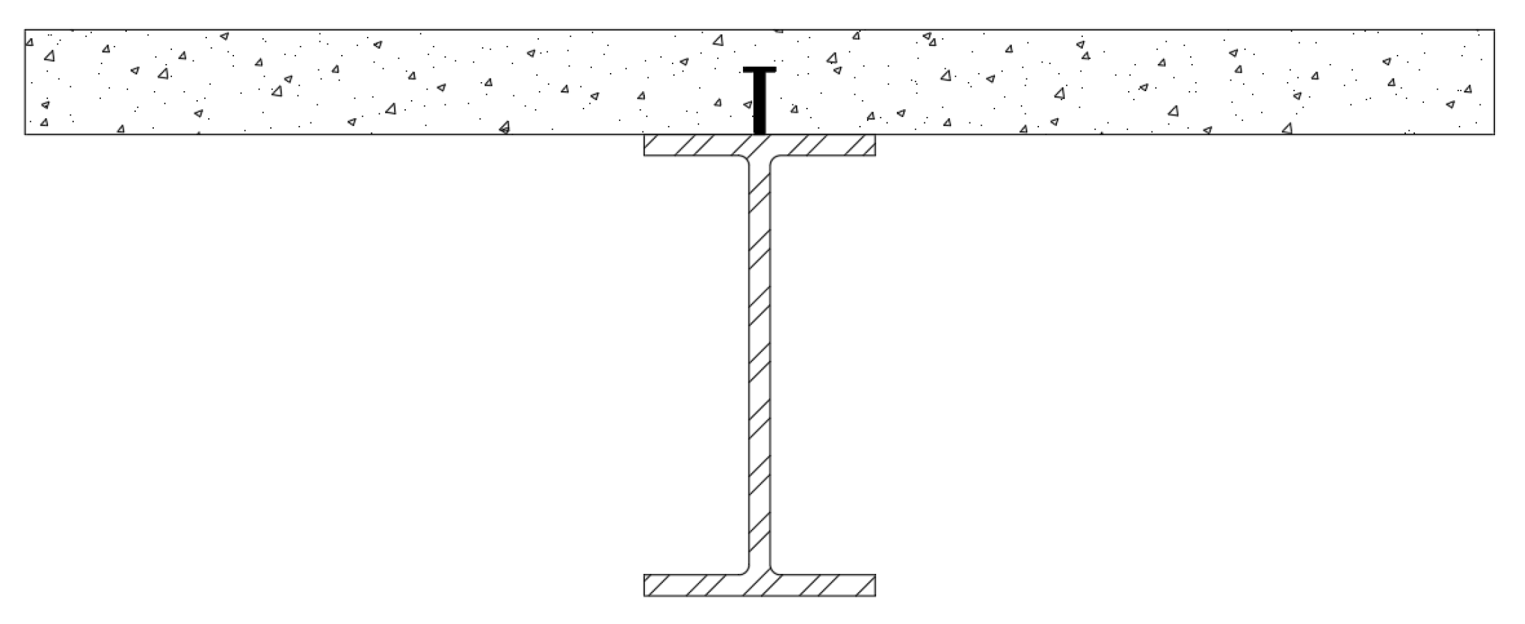
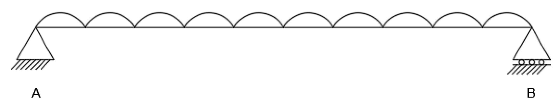
The structure in question is a single steel-concrete composite beam, comprising a universal I beam section, profiled steel sheeting, shear connectors, and a concrete slab with steel mesh reinforcement (Figure 1). This form of construction is common for a variety of building types, including high rise buildings. The beam is assumed to be simply supported (Figure 2) and can be considered as either a primary beam spanning between two columns, or a secondary beam spanning between other beams.
3.2. Actions upon the Structure
With the omission of columns and lateral stability systems, only load cases in a vertical direction are to be considered for this work. These are for actions on the structure during the construction stage, and during the composite stage after the curing of the concrete slab. Calculation of both permanent and variable actions are in kN/m2. For the construction stage, permanent action gk is calculated as the sum of both the steel cross-section and the profiled steel decking. Variable action qk is the sum of the construction loading and the wet self-weight of the concrete slab. For the composite stage, permanent action is calculated as the sum of the steel cross-section, profiled steel sheeting, dry self-weight of the concrete slab, and an assumed loading for finishes. Variable action is taken as 2.5kN/m2 for a general use office area above ground level [26]. The greatest values for both gk and qk are taken as governing and taken forward to calculating a combination of actions (Fd) in accordance to Equations (6) and (10) from Eurocode 0 [27]. Partial factors of safety for the permanent action γg is taken as 1.35, for variable action γq is taken as 1.5 from the UK National Annexe to Eurocode – Basis of Structural Design BS EN 1990:2002+A1:2005 [28].
3.3. Ultimate Limit State Verification
With the design combination of actions calculated, this is worked into design moment MEd and shear force VEd acting upon the structure, where:
Next, design checks in accordance with Eurocode 4: Design of Composite Steel and Concrete Structures BS EN 1994-1-1:2004 [24] are undertaken. Beginning with determining moment capacity for full shear connection Mpl,Rd, where:
Design moment capacity verified by:
Assuming circumstances where the shear connection is not full, shear connection resistance PRd and degree of shear connection Rq are calculated, where PRd is:
and where Rq is;
Degree of shear connection verified by:
With the minimum required shear connection also calculated:
With the determination of partial shear connection, corresponding moment capacity for partial shear MRd can be determined.
Moment capacity verified by:
Resistance to vertical shear Vpl,Rd considers the steel section only, and therefore is calculated in accordance with Eurocode 3: Design of Steel Structures BS EN 1993-1-1 [29], where:
Vertical shear capacity verified by:
Finally, in accordance with Eurocode 2: Design of Concrete Structures BS EN 1992-1-1 [30] the transverse reinforcement within the slab can be designed, and the crushing of the concrete strut can be checked. For reinforcement design:
This calculation returns the minimum required cross-sectional area per m of slab. An actual cross-sectional area of reinforcement is provided in accordance with manufacturer’s data [31]. Crushing of the concrete strut check is undertaken according to:
3.4. Serviceability Limit State Verification
For determining the deflected shape of the structure, first, the following assumptions are made:
- At the construction stage, the beam alone is assumed to have insufficient resistance to lateral-torsional buckling and will be fully propped, thus for this scenario, there is no deflection of the beam.
- The beam is assumed to be an internal beam; therefore, relative humidity is assumed as 50%.
- It is assumed that the cement used for the slab is normal hardening, thus class = N.
To begin, owing to the concrete component of the structure, the creep coefficients are determined from these input assumptions using Figure 3.1 of Eurocode 2: Design of Concrete Structures BS EN 1992-1-1 [16] to determine coefficients for concrete with 1-day and 28-day strengths. Shrinkage is determined by calculating the total shrinkage strain εcs where;
Basic drying shrinkage strain εcd is determined by:
Autogenous shrinkage strain is determined by:
For the composite section, four conditions contribute to the deflected shape of the structure; short term loading, permanent loading, creep, and shrinkage primary effects. The effective flexural stiffness of the composite section is calculated by the general Equation (33):
where:
When:
Next, deflections can be calculated using general formula:
where deflections are due to permanent actions δ1:
where deflections are due to variable actions δ2.1:
where deflections are due to creep under the semi-permanent value of variable actions δ2.2:
where deflections are due to shrinkage δ2.3:
Deflections must be within allowable limits, as the final checks for SLS for total deflection due to permanent action, variable action, creep and shrinkage:
For total variable action, creep and shrinkage:
3.5. Quantification of Embodied Energy
Candidate designs that meet the criterion for ULS and SLS verification will be subject to quantification of embodied energy. Owing to the simple nature of the structure, operational energy is omitted from the whole life assessment, and only the initial embodied energy EEi of the structure will be quantified as per Equation (49) [32].
where Mi is the quantity of material (i), Mi is the cradle to gate energy content of the material (i) per unity quantity, and Ec is the energy used on-site for construction. As the form of the beam under assessment is not variable (i.e., a single simply supported composite beam), the energy consumption for construction is assumed to be constant, and therefore is omitted from the assessment. Similarly, energy consumption for the transport of materials to the site is assumed to be constant, and therefore is also omitted from assessment [32].
The Inventory of Carbon & Energy (ICE) [33] is the most well-documented database source of energy constants for materials up to date. The boundary conditions for global values from ICE for the components of the structure consider energy embodied from cradle to gate (i.e., energy to extract raw material), and all processes to produce construction products up to, but not including transport to site.
Material quantities Mi is to be calculated by the specific component geometries of the candidate designs. For simplification, quantified components are to be limited to the steel universal beam, steel shear connectors, profiled steel sheeting, reinforcing steel, and slab concrete. Supporting columns and connections are assumed to be constant for all candidate designs, and therefore can be omitted from the assessment.
As a simple quantification of embodied energy in terms of total energy content in MJ of the structure, owing to the simplicity of the structure under analysis, it was reasonable to adopt energy per weight as the unit of quantification. It is anticipated that as this work progresses to more complex floor plate structures, it may be more appropriate to utilise more functional units for quantification.
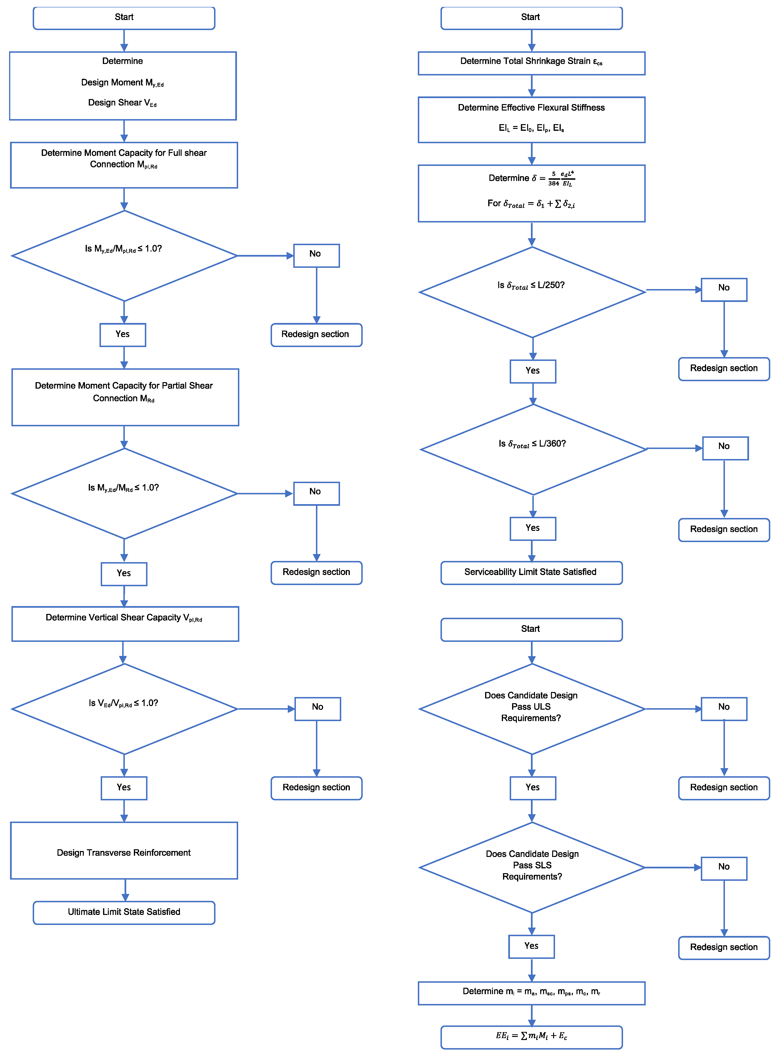
A flowchart of the design and embodied energy quantification processes can be seen in Figure 3.
4. MATLAB Scripts for Optimisation
4.1. General MATLAB Script for Structural Design and Life Cycle Energy Assessment
To optimise the stated objective functions, a MATLAB script was assembled to enable the processes denoted in Section 2 to be undertaken and incorporated with the GA optimiser within MATLAB Global Optimisation Toolbox.
Part 1—Determines the combined actions Fd in accordance to Equations (6.10) of Eurocode 0. Fd is calculated applied to the overall floor area supported by the beam, as floor area is required as an input for later functions. A dedicated MATLAB function is utilised for this purpose. Design moment MEd, and design shear VEd, according to Equations (1) and (2) from Section 3.2 are also calculated in the part of the script.
Part 2—Ultimate limit state verification determines the processes for verification of moment capacity, shear capacity, design of transverse reinforcement and crushing of the concrete strut stated within Section 3.3 (Equations (3)–(25)).
Part 3—Serviceability limit state verification determines combined deflections due to permanent actions, variable actions, creep effects and shrinkage stress in accordance with Section 3.4 (Equations (26)–(40)). Checks of allowable deflection areas also undertaken (Equations (41) and (42)).
Part 4—Embodied energy quantification determines the number of materials in terms of kg from calculated volumes or areas. These are multiplied by materials factors and the results totalled in accordance with Section 3.5 (Equation (49)).
4.2. Implementing MATLAB Global Optimisation Toolbox GA
To implement the GA optimiser within MATLAB Global Optimisation Toolbox, firstly the objective function needs to be presented as a MATLAB function. This requires establishing the respective general equation to determine the objective function, the corresponding parameters and corresponding variables. This function when saved is called upon as the fitness function or FitFcn within the GA script.
The GA script can then be constructed with MATLAB. To begin, the constants of the fitness function should be listed and assigned values. Next, the remaining components for the GA should be defined. First, the fitness function should be called upon, and all variables (xi) and parameters of this function should be included. Next, the GA number of variables (nvars) within the fitness function needs to be defined for the GA program. Next, the lower (lb) and upper (ub) bounds of the variables need to be included. These bounds apply a constraint upon the respective script by limiting the range of variables in line with the feasible variable limits. For multiple variables, these limits should be vectorised like so:
Next, the optimisation options (optimoptions) should be defined. This includes selecting the GA optimiser, establishing the number of generations, setting the stopping criteria of the program, and plotting of outputs. Finally, these components are assembled in the following order:
where x returns the variable values for the optimised objective function fval. Upon construction of this script, the process is ready to be initialised.
| [x,fval] = ga(FitFcn,nvars,[],[],[],[],lb,ub,[],options); |
5. Optimisation of a Steel-Concrete Composite Beam
5.1. Minimisation of the Universal Beam Section—Objective Function 1
To begin, the structural design script was given an initial candidate design to establish benchmarks for design moment MEd, as well as an outputted, embodied energy content. This was done with the following components:
- A 305 × 102 × 25 universal beam with a span length of 6.0m, and bay spacing of 3.0m;
- A 130 mm deep C25/30 concrete slab cast upon;
The structure passes all ULS and SLS requirements and the energy output of this script was a total of 23493.6 MJ for the entire structure. A breakdown of the material contributions to this embodied energy quantification can be seen in Table 1. With an MEd output of 119.4 kNm, the moment capacity for full shear connection Mpl,Rd output was calculated as 257.8 kNm. In accordance with Equation (8), the check value was 0.46, less than half the check value of 1.0, implying reduction of the UB is achievable.
To minimise the UB section, the GA process was introduced to minimise the depth of the section (ha). First, a fitness function ha_function was written in MATLAB, based upon Equation (3) rearranged to make ha the subject.
Production of both the fitness function and GA script gives the following:
| function ha = ha_function(x, Npla, dslab, NcSLAB, hc) ha = ((2*(x*10^3))/Npla)-(2*dslab)+((Npla*hc)/NcSLAB); end % %Genetic Algorithm Script for Objective Function 1 - Minimise Universal %Beam Section. % clc, clear, clear all % %Define Parameters hc = 70; dslab = 130; Npla = 987.25; NcSLAB = 1487.5 %Define GA Components FitFcn = @(x)ha_function(x,Npla,dslab,NcSLAB,hc); nvars = 1; lb = 120; ub = 257.79; options = optimoptions(‘ga’,’Generations’,50,... ‘MaxStallGenerations’,Inf,’PlotFcn’,@gaplotbestf); [x,fval] =ga(FitFcn,nvars,[],[],[],[],lb,ub,[],options); x fval |
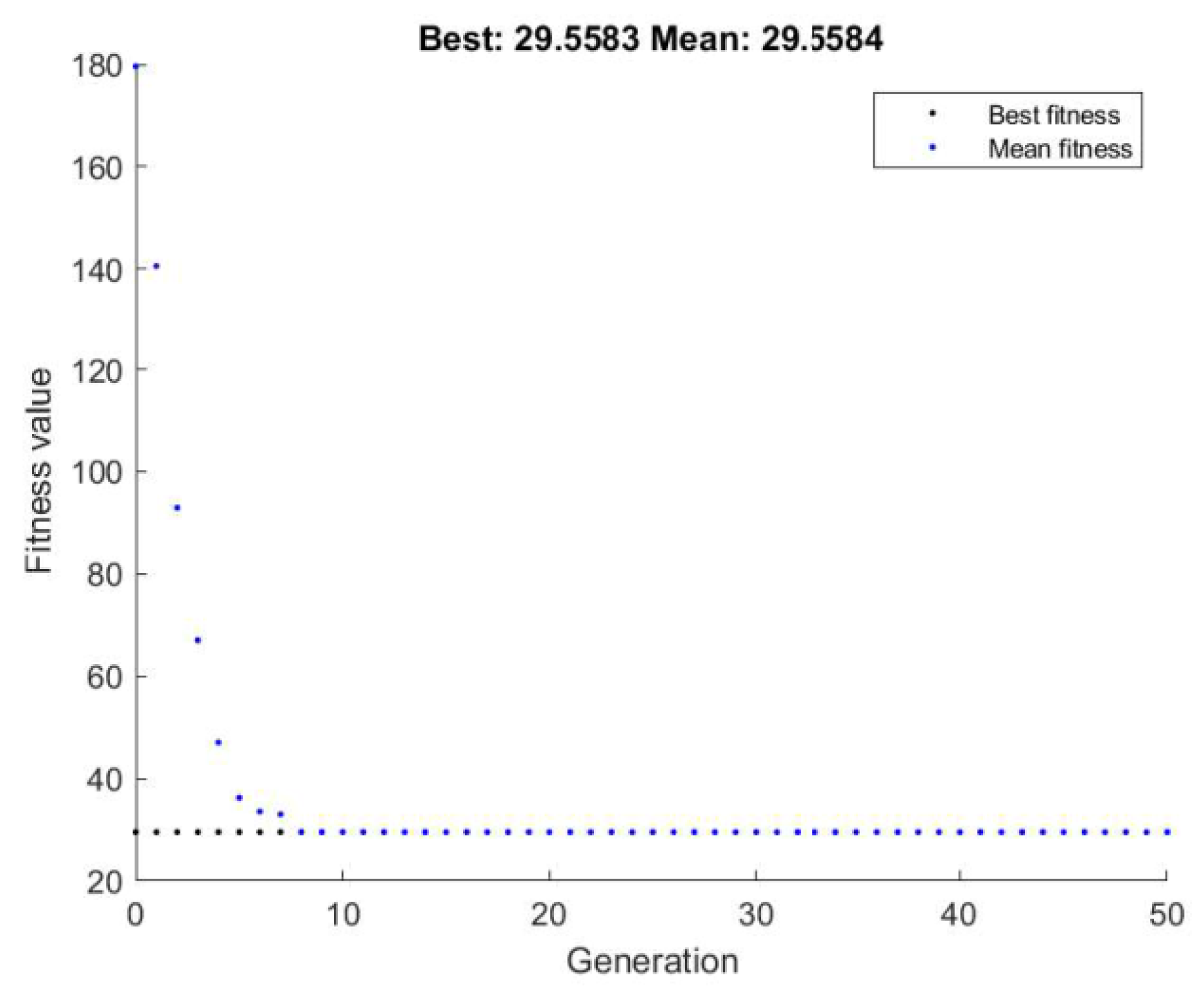
For the fitness function, Mpl,Rd was set as the variable (x), where other parameters were retained as constants. The GA program calls upon ha_function as the required fitness function. The lower bound for Mpl,Rd was set to MEd rounded to the nearest whole number, to constrain the GA to prevent it from determining a depth of beam that would fail ULS checks. The upper bound for Mpl,Rd was set to the computed Mpl,Rd of the initial candidate design. This was to provide a practical upper bound that would prevent a solution having a depth greater than the initial candidate design. With a single variable, nvars was set to 1. Finally, options were set to give a run of 50 generations with MATLAB default population sizes of 50. A stopping criterion of infinite generations (MaxStallGenerations) was also included to ensure convergence during test runs of the script. This option was included for completeness, however, was overridden by setting generations to 50. Finally, the best and mean outputs (fval) per generation were plotted against their respective generation (Figure 4) to visualise the convergence of the GA to a solution.
For this objective function, convergence upon a solution occurred after seven generations, giving a minimised ha of 29.3 mm. This was a depth smaller than the stock blue book sections and is unfeasible for the remaining design checks. To determine a solution that passes the ULS and SLS criteria, sections were manually cycled through until the minimum UB section of a 203 × 102 × 32 section was selected for assessment with the same span length and concrete slab depth as the initial candidate design. The total initial embodied energy of this revised design was 22367.5 MJ, a 4.8% reduction compared to the initial candidate design. A breakdown of material contribution to this embodied energy quantification is included in Table 1.
5.2. Minimisation of Depth of the Concrete Slab—Objective Function 2
This optimisation utilised the same span length and UB section as the initial candidate design. To minimise the concrete slab depth, the GA process was introduced again, however requiring a new fitness function to operate. The fitness function dslab_function was written in MATLAB, also based upon Equation (3), this time rearranged to make dslab the subject.
Production of both the fitness function and GA script gives the following:
| function dslab = dslab_function(x,Npla,NcSLAB,ha,hc) dslab=((x*10^3)/Npla)-(ha/2)+((Npla*hc)/(2*NcSLAB)); end %Genetic Algorithm Script for Objective Function 2 - Minimise depth of %concrete slab. % clc, clear, clear all % %Define Parameters hc = 70; ha = 308.7; Npla = 987.25; NcSLAB = 1487.5 %Define GA Components FitFcn = @(x)dslab_function(x,Npla,NcSLAB,ha,hc); nvars = 1; lb = 120; ub = 257.79; options = optimoptions(‘ga’,’Generations’,10,... ‘MaxStallGenerations’,Inf,’PlotFcn’,@gaplotbestf); [x,fval] =ga(FitFcn,nvars,[],[],[],[],lb,ub,[],options); x fval |
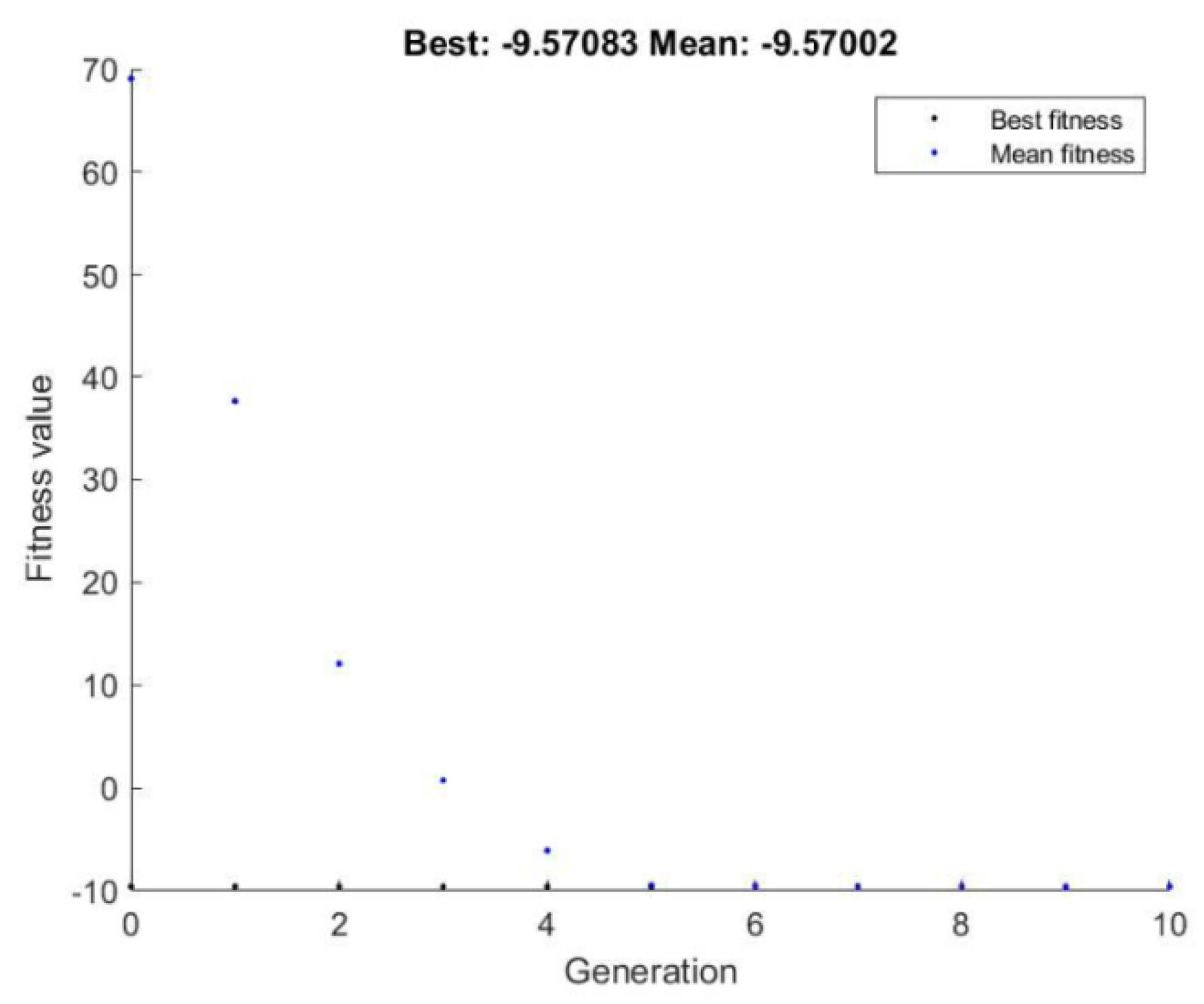
As with objective function 1, Mpl,Rd was set as the variable (x), and the remaining parameters retained as constants. The GA program called upon dslab_function as the required fitness function. Lower and upper bounds for Mpl,Rd were the same as for objective function 1 as the benchmark span and beam conditions from the initial candidate design were still valid. With a single variable, nvars was again set to 1. For this objective function, the MATLAB population size of 50 was retained. Initially the number of generations was kept at 50, however, as convergence occurred within 5 generations, this reduced to 10 to enable the convergence to be better graphically visualised (Figure 5).
Upon convergence, the GA gave a minimes dslab of −9.57. Numerically this follows Equation (51) accurately, however reaping a negative value is an unfeasible design. To determine a feasible solution, the shallowest slab depth in accordance with manufacturer information [34] of 110 mm was run along with the initial candidate design span length and UB section through the structural design script. This structure passed both ULS and SLS criteria and returned a total initial embodied energy of 22534.6 MJ, a 4.1% reduction of embodied energy compared to the initial candidate design. A breakdown of material contribution is included in Table 1.
5.3. Minimisation of Overall Weight of the Composite Beam—Objective Function 3
For this objective function, the span length and bay spacing were assumed the same as the initial candidate design. Consequently, as the floor area remained the same, the quantity of profiled decking and shear connectors remained the same. As the UB section was minimised in objective function 1, and the concrete slab depth was reduced in objective function 2, for this assessment a 203 × 102 × 23 UB with a 110 mm slab was utilised. Running these respective inputs through the structural design script, the structure passed ULS and SLS criteria and returned a total initial embodied energy of 21408.5 MJ for the structure; a reduction of 8.9% compared to the initial candidate design. A breakdown of material contribution is included in Table 1.
5.4. Maximisation of the Span Length of the Composite Beam—Objective Function 4
Building on the reduction of total initial embodied energy from objective functions 1–3, this objective function seeks to maximise the span length for the reduced UB section and concrete slab depth. The output Mpl,Rd of objective function 3 was calculated at 155.7 kNm, with a Fd of 2076kN imposed on the entire floor area. Rearranging Equation (1) gave a theoretical span length of 7.832 m for a 203 × 102 × 23 UB with a 110 mm concrete slab over a bay spacing of 3.0 m. However, running these inputs through the structural design script, the design failed both the ULS and the SLS criteria. Manually cycling through sections to ensure these criteria were met returned a design with a 254 × 102 × 28 UB. This returned a total initial embodied energy content of 29,410.9 MJ, a 25.2% increase for a 30.4% increase in span, and a proportionally 5.4% increase in total initial embodied energy, assuming a 30.4% increase of 21,408.5 MJ = 27,916.1 MJ.
5.5. Minimisation of the Deflection of the Composite Beam—Objective Function 5
Returning to a 6m span as per the initial candidate design, in accordance with Equation (47), the maximum deflection for SLS was limited to 24 mm. As calculated by the structural design formulae and the life cycle environmental assessment (LCEA) script, objective function 3, with the lightest components, δtotal was returned as 17.4 mm. Running the structural design and LCEA script with the next largest UB section found in the blue book [36] a 203 × 133 × 25, returned a deflection of 16.5 mm, however it also returned a total initial embodied energy content of 21,849.2 MJ, a 2.1% increase when compared to objective function 3. A breakdown of material contribution is included in Table 1.
6. Concluding Remarks
In this study, a MATLAB script has been produced to enable the verification of the ULS and SLS of a steel-concrete composite beam in accordance with Eurocode 4 (parts 1–3) [24]. Additionally, LCEA is included to determine the total initial embodied energy content of the beams verified by parts 1–3 of the script. This enabled the GA optimiser from the MATLAB Global Optimisation Toolbox to be implemented for optimising five objective functions.
Initially, this MATLAB script was used to run an analysis on a typical steel-concrete composite beam. The purpose of this initial candidate design was to establish benchmark conditions for structural performance in terms of ULS and SLS, and for embodied energy quantification. These benchmark values served as parameters to begin the optimisation process, and also outputs for the optimised objective functions to be compared against.
Objective function 1 had the aim to minimise the UB section of the composite beam. By implementing the MATLAB script in conjunction with the GA optimiser, it was possible to reduce the UB section, by reducing the depth of the section ha. Numerically, the output returned was accurate to the design process, but had a minimum value signification smaller than the shallowest UB section readily available; not a representative section. This required manual intervention to determine the smallest UB section that satisfied all ULS and SLS criteria. Regardless, an overall reduction in the total initial embodied energy of 4.8% was achieved. Moving forward, further refinement of the scripting is required to automate the selection of suitable UB sections.
Objective function 2 had the aim to reduce the depth of the concrete slab. Like objective function 1, it was possible to use the MATLAB script and GA optimiser to reduce the depth of the slab while numerically staying true to the structural design process. However, as the output returned effectively eliminated any depth of the slab, further refinement to the scripting is required to ensure a minimum depth is achieved within practical limits. Assuming the shallowest practical depth of the slab, the total initial embodied energy can be reduced by 4.1%.
To reduce overall weight for objective function 3, a combination of the results of objective functions 1 and 2 and consistent beam span/spacing as the initial candidate design were used. It was possible to determine a design that achieved a reduction of 8.9% of total initial embodied energy whilst satisfying all ULS and SLS criteria.
Building upon the outputs of objective functions 1–3, objective function 4 aimed to maximise the span length of the composite beam. Adjusting Equation (1), it gave a theoretical maximum length. When proportionally comparing the energy content of the objective function 3 design, and design for objective function 4, a 5.4% increase in total initial embodied energy was returned. This is a result of the overall increase in material quantity.
For objective function 5, again the combination of reduced UB section and slab depth resulted in the best performer for satisfying ULS and SLS criteria as well as minimised energy content. However, it was shown that increasing the UB section in an attempt to reduce the overall deflection returned a predictable increase in energy content, in this instance as a 2.1% increase against the initial candidate design.
In summary, these objective functions have been applied to a simply supported steel-concrete composite beam, with the best design selected from the lowest resultant initial embodied energy. Objective functions 1–3 and 5 return a reduction in the initial embodied energy. For objective function 4, an increased span length naturally increases the initial embodied energy. For more complex structures, such as a structural grid or a complete floor plate, otherwise for an analysis including more components and/or supporting members, it is envisaged that this increased complexity will introduce a greater degree of variety on the design parameters and subsequent outputs. Therefore, it is recommending that all objective functions are implemented to assess which scenario returns the minimal initial embodied energy value. In addition, it is suggested that the available steel sections are introduced into the MATLAB tool, and create an automated selection based on the values returned from the objectives all together, to assist practising engineers with quick results.
Author Contributions
Both authors have contributed equally to the work. A.H.W. was supervised by K.D.T. during his research studies in the School of Civil Engineering at the University of Leeds. The background work has been carried out by both authors, the computational work was conducted by the first author and supervised by the second one. Both authors have contributed to the writing of the paper. All authors have read and agreed to the published version of the manuscript.
Funding
This research was funded by the Engineering and Physical Sciences Research Council in the UK (EP/L504993/1).
Acknowledgments
This work is part of a larger research project on dealing with the utilisation of optimisation algorithms to optimise steel-concrete composite structures in terms of their embodied energy demand. The authors would like to thank the sponsors of this research work, the Engineering and Physical Sciences Research Council (EP/L504993/1) for the financial support and WSP London for both their financial and technical support.
Conflicts of Interest
There are no conflicts of interest to declare.
Nomenclature
| GA | Genetic Algorithm |
| UB | Universal Beam |
| ULS | Ultimate Limit State |
| SLS | Serviceability Limit State |
| MEd | Design Bending Moment |
| VEd | Design Shear Force |
| gk | Permanent Action |
| qk | Variable Action |
| γg | Partial Factor of Safety for Permanent Actions |
| γq | Partial Factor of Safety for Permanent Actions |
| γM0 | Partial Factor for Resistance–Structural Steel |
| γc | Partial Factor for Resistance–Concrete |
| γs | Partial Factor for Resistance–Reinforcing Steel |
| γv | Partial Factor for Resistance–Shear Connectors |
| Fd | Combined Actions |
| ha | Depth of Universal Beam |
| ba | Width of Universal Beam |
| d | Depth Between Fillets |
| tw | Web Thickness |
| tf | Flange Thickness |
| r | Radius of Root Fillet |
| Aa | Area of Universal Beam |
| Wpl,y | Universal Beam Plastic Modulus (y-y axis) |
| Iyy | Universal Beam Second Moment of Area (y-y axis) |
| Ia | Universal Beam Second Moment of Area (dominant axis) |
| L | Beam Span |
| S | Beam Spacing |
| dslab | Depth of Slab |
| hc | Height of Concrete Above Profile |
| hp | Height of Profiled Deck |
| b1 | Width of Bottom Trough |
| b2 | Width of Top Trough |
| Ø | Nominal Diameter of Shear Connector |
| hsc | Height of Shear Connector prior to Welding |
| Fy | Yield Strength of Structural Steel |
| Fu | Ultimate Strength of Structural Steel |
| Fyk | Yield Strength of Reinforcing Steel |
| Fck | Cylinder Strength of Concrete |
| Ecm | Secant Modulus of Elasticity |
| beff | Effective Width of the Compression Flange |
| Nc,slab | Compression Resistance of the Concrete Slab |
| Npla | Tensile Resistance of the Steel Section |
| Mpl,Rd | Moment Capacity for Full Shear Connection |
| PRd | Design Shear Resistance of a Single Shear Connector |
| kt | Deck Shape Influence Factor |
| Mpl,a,Rd | Plastic Moment Resistance of the Universal Beam |
| MRd | Moment Capacity for Partial Shear Connection |
| Vpl,Rd | Vertical Shear Resistance of the Composite Beam |
| Av | Area of Shear |
| Asf | Cross Sectional Area of Reinforcing Steel |
| Fyd | Yield Strength of Reinforcing Steel |
| εcs | Total Shrinkage Strain |
| εcd | Drying Shrinkage Strain |
| εca | Autogenous Shrinkage Strain |
| fcm(t) | Minimum Concrete Strength for Time (t) |
| RH | Relative Humidity |
| EL | Effective Modulus of Elasticity of Concrete |
| E0 | Short Term Effective Modulus of Elasticity of Concrete |
| Ep | Permanent Effective Modulus of Elasticity of Concrete |
| Es | Effective Modulus of Elasticity of Concrete for Shrinkage |
| Ic | Second Moment of Area of Concrete Flange |
| EIL | Effective Flexural Stiffness of Concrete Flange |
| EI0 | Short Term Effective Flexural Stiffness of Concrete Flange |
| EIp | Permanent Effective Flexural Stiffness of Concrete Flange |
| EIs | Effective Flexural Stiffness of Concrete Flange for Shrinkage |
| Φ(t,t0) | Creep Coefficient |
| δi | ith Deflection Component |
| δtotal | Total Deflection |
| ed | Combined Actions for Serviceability Limit State |
| ac | Distance Between Centroidal Axes of Concrete Flange and Universal Beam |
| EEi | Initial Embodied Energy Content of Steel-Concrete Composite Beam |
| EEtotal | Total Initial Embodied Energy Content of Steel-Concrete Composite Beam |
| EEa | Initial Embodied Energy Content of Universal Beam |
| EEsc | Initial Embodied Energy Content of Shear Connectors |
| EEps | Initial Embodied Energy Content of Profiled Deck |
| EEc | Initial Embodied Energy Content of Concrete Slab |
| EEr | Initial Embodied Energy Content of Reinforcing Steel |
| mi | Quantity of Material (i) |
| Mi | Cradle to Gate Embodied Energy Content for Material (i) |
| Ec | Embodied Energy Content for Construction Activities |
References
- Ahmed, I.; Tsavdaridis, K.D.; Neysari, F. A new breed of sustainable ultra-lightweight and ultra-shallow steel-concrete composite flflooring system: Life cycle assessment (LCA) of materials. In Proceedings of the International Conference Coordinating Engineering for Sustainability and Resilience (CESARE 2017), Dead Sea, Jordan, 3–8 May 2017; pp. 3–8. [Google Scholar]
- Ahmed, I.; Tsavdaridis, K.D.; Neysari, F. Push-out shear tests for a novel pre-fabricated shallow steel-concrete composite flflooring system. In Proceedings of the 12th International Conference on Advances in Steel-Concrete Composite Structures (ASCCS 2018), Valencia, Spain, 27–29 June 2018; pp. 27–29. [Google Scholar]
- Ahmed, I.; Tsavdaridis, K.D. Prefabricated Composite Flooring Systems with Normal and Lightweight Concretes. In Proceedings of the The 14th Nordic Steel Construction Conference (NSCC 2019), In Special Issue Proceedings of Nordic Steel, (DTU), Copenhagen, Denmark, 18–20 September 2019; Volume 3, pp. 257–263. [Google Scholar]
- Ahmed, I.M.; Tsavdaridis, K.D. Life Cycle Assessment (LCA) Study of European Lightweight Composite Flooring Systems. J. Build. Eng. 2018, 20, 624–633. [Google Scholar] [CrossRef]
- Ahmed, I.M.; Tsavdaridis, K.D. The Evolution of Composite Flooring Systems: Applications, Testing, Modelling and Eurocode Design Approaches. J. Constr. Steel Res. 2019, 155, 286–300. [Google Scholar] [CrossRef]
- Tsavdaridis, K.D.; D’Mello, C. Finite Element Investigation of Perforated Beams with Different Web Opening Configurations. In Proceedings of the The 6th International Conference on Advances is Steel Structures (ICASS 2009), Hong Kong, China, 16–18 December 2009; pp. 213–220. [Google Scholar]
- Tsavdaridis, K.D.; D’Mello, C.; Hawes, M. Experimental Study of Ultra Shallow Floor Beams (USFB) with Perforated Steel Sections. In Proceedings of the The 11th Nordic Steel Construction Conference 2009 (NSCC 2009), Malmö, Sweden, 2–4 September 2009; Volume 128, pp. 312–319. [Google Scholar]
- Tsavdaridis, K.D.; D’Mello, C.; Huo, B.Y. Experimental and Computational Study of Vertical Shear Behaviour of Partially Encased Perforated Steel Beams. Eng. Struct. 2013, 56, 805–822. [Google Scholar] [CrossRef]
- Tsavdaridis, K.D.; Galiatsatos, G. Assessment of Cellular Beams with Transverse Stiffeners and Closely Spaced Web Openings. Thin Walled Struct. 2015, 94, 636–650. [Google Scholar] [CrossRef] [Green Version]
- Demetriou, D.; Nikitas, N.; Tsavdaridis, K.D. Performance of Fixed-Parameter Control Algorithms on High-Rise Structures Equipped with Semi-Active Tuned Mass Dampers. Struct. Des. Tall Spec. Build. 2015, 25, 340–354. [Google Scholar] [CrossRef] [Green Version]
- Demetriou, D.; Nikitas, N.; Tsavdaridis, K.D. Semi Active Tuned Mass Dampers of Buildings: A Simple Control Option. Am. J. Eng. Appl. Sci. Spec. Issue Struct. Eng. 2015, 8, 620–632. [Google Scholar] [CrossRef]
- Tsavdaridis, K.D.; D’Mello, C. Optimisation of Novel Elliptically-Based Web Opening Shapes of Perforated Steel Beams. J. Constr. Steel Res. 2012, 76, 39–53. [Google Scholar] [CrossRef]
- Tsavdaridis, K.D.; Kingman, J.J.; Toropov, V.V. Application of Structural Topology Optimisation to Perforated Steel Beams. Comput. Struct. 2015, 158, 108–123. [Google Scholar] [CrossRef] [Green Version]
- Kingman, J.J.; Tsavdaridis, K.D.; Toropov, V.V. Applications of Topology Optimisation in Structural Engineering: High-rise Buildings & Steel Components. Jordan J. Civ. Eng. 2015, 9, 335–357. [Google Scholar]
- Hawdon-Earl, S.; Tsavdaridis, K.D. Form Finding and Dimensioning of Reinforced Concrete Shell Roof for Akrotiri (Santorini). J. Int. Assoc. Shell Spat. Struct. (IASS) 2018, 59, 198. [Google Scholar]
- Fraser, A.S. Simulation of Genetic Systems by Automatic Digital Computers. Aust. J. Biol. Sci. 1957, 10, 484–491. [Google Scholar] [CrossRef]
- Panchal, D.R. Steel-Concrete Composite Beam Design Using Genetic Algorithms. Int. J. Innov. Res. Dev. 2014, 3, 473–480. [Google Scholar]
- Alanka, K.; Chaudhary, S. Cost Optimisation of Composite Beams using Genetic Algorithm and Artificial Neural Network. In Proceedings of the 2012 International Conference on Computer Technology and Science (ICCTS), New Delhi, India, 18–19 August 2012. [Google Scholar]
- Senouci, A.B.; Al-Ansari, M.S. Cost Optimisation of Composite Beams using Genetic Algorithms. In Advances in Engineering Software; Elsevier: Amsterdam, The Netherlands, 2009; Volume 40, pp. 1112–1118. [Google Scholar]
- Artar, M.; Daloglu, A.T. Optimum Design of Composite Steel Frames with Semi-Rigid Connections and Column Bases via Genetic Algorithm. Steel Compos. Struct. 2015, 19, 1035–1053. [Google Scholar] [CrossRef]
- Eleftheriadis, S.; Dunant, C.F.; Drewniok, M.P.; Rogers-Tizard, W. A Computational Paradigm for the Optimisation of Steel Building Structures Based on Cost and Carbon Indexes in Early Design Stages. In Proceedings of the 24th International Workshop on Intelligent Computing in Engineering (EG-ICE-2017), University of Nottingham, Nottingham, UK, 10–12 July 2017. [Google Scholar]
- Eleftheriadis, S.; Dunant, C.F.; Drewniok, M.P.; Rogers-Tizard, W.; Kyprianou, C. Comparative Numerical Analysis for Cost and Embodied Carbon Optimisation of Steel Building Structures. Adv. Comput. Des. 2018, 3, 385–404. [Google Scholar]
- MathWorks. Global Optimisation Toolbox Version R2019A.S.I:S.N; 2019. [Google Scholar]
- CEN. European Committee for Standardisation. In Eurocode 4: Design of Steel and Concrete Composite Structures Part 1-1: General Rules and Rules for Buildings; CEN: Brussels, Belgium, 2005. [Google Scholar]
- Mitchell, M. An Introduction to Genetic Algorithms; First MIT paperback, Ed.; Massachusetts Institute of Technology: Cambridge, MA, USA, 1996. [Google Scholar]
- CEN European Committee for Standardisation. Eurocode 1 Actions on Structures-Part 1-1: General Actions-Densities, Self-Weight, Imposed Loads for Buildings; European Committee for Standardisation: Brussels, Belgium, 2002. [Google Scholar]
- CEN European Committee for Standardisation. Eurocode: Basis of Structural Design; European Committee for Standardisation: Brussels, Belgium, 2002. [Google Scholar]
- British Standards Institute. UK National Annex to Eurocode 1. Actions on Structures. In General Actions-Densities, Self-Weight, Imposed Loads for Buildings; British Standards Institute: London, UK, 2005. [Google Scholar]
- CEN. European Committee for Standardisation. In Eurocode 3: Design of Steel Structures-Part 1-1: General Rules and Rules for Buildings; CEN: Brussels, Belgium, 2006. [Google Scholar]
- CEN. European Committee for Standardisation. In Eurocode 2: Design of Concrete Structures-Part 1-1: General Rules and Rules for Buildings; CEN: Brussels, Belgium, 2004. [Google Scholar]
- Heaton Products LTD. 2019. Reinforcement Mesh. Available online: https://www.heatonproducts.co.uk/products/reinforcement-mesh/ (accessed on 27 April 2019).
- Ramesh, T.; Prakesh, R.; Shukla, K.K. Life cycle Energy Analysis of Buildings: An Overview. Elsevier. Energy Build. 2010, 42, 1592–1600. [Google Scholar] [CrossRef]
- Hammond, G.P.; Jones, C.I. Inventory of Carbon and Energy (ICE); University of Bath: Bath, UK, 2008. [Google Scholar]
- Tata Steel. ComFlor® Manual Composite Floor Decking Design and Technical Manual; Tata Steel UK Limited: London, UK, 2017. [Google Scholar]
- SMD. Best Practice Data Sheet DATA/11 SMD Shear Studs SMD.DAT.152.V4; SMD Stockyards Limited; Available online: http://smdltd.co.uk/wp-content/uploads/2016/06/SMD.DAT_.152.V4-Best-Practice-Data-Sheet-DATA.11-SMD-Shear-Studs.pdf (accessed on 12 April 2020).
- Steel Construction Info. Universal Beams Interactive ‘Blue Book’. Available online: https://www.steelforlifebluebook.co.uk/ub/ec3-ukna/section-properties-dimensions-properties/ (accessed on 1 May 2019).
Figure 1.
Typical steel-concrete composite beam section.

Figure 2.
Simple supported beam.

Figure 3.
Design and embodied energy quanitification processes.

Figure 4.
MATLAB plot of Objective function 1.

Figure 5.
MATLAB plot of objective function 2.


Table 1.
Embodied energy quantity outputs for objective functions.
| Objective Function | UB Section | Slab Depth (mm) | Span (m) | EEa (MJ) | EEsc (MJ) | EEps (MJ) | EEc (MJ) | EEr (MJ) | EEtotal (MJ) |
|---|---|---|---|---|---|---|---|---|---|
| Initial Candidate Design | 305 × 102 × 28 | 130 | 6.0 | 6226.6 | 293.0 | 8143.0 | 4795.2 | 4035.8 | 23,493.6 |
| Minimised Universal Beam Section | 203 × 102 × 23 | 130 | 6.0 | 5100.5 | 293.0 | 8143.0 | 4795.2 | 4035.8 | 22,367.5 |
| Minimised Depth of Concrete Slab | 305 × 102 × 28 | 110 | 6.0 | 6226.6 | 293.0 | 8143.0 | 3836.2 | 4035.8 | 22,534.6 |
| Minimised Weight | 203 × 102 × 23 | 110 | 6.0 | 5100.5 | 293.0 | 8143.0 | 3836.2 | 4035.8 | 21,408.5 |
| Maximised Span Length | 254 × 102 × 28 | 110 | 7.823 | 8147.2 | 383.9 | 10617.0 | 5001.7 | 5262.1 | 29,410.9 |
| Minimised Deflection | 203 × 133 × 25 | 110 | 6.0 | 5542.1 | 293.0 | 8143.0 | 3836.2 | 4035.8 | 21,849.2 |
© 2020 by the authors. Licensee MDPI, Basel, Switzerland. This article is an open access article distributed under the terms and conditions of the Creative Commons Attribution (CC BY) license (http://creativecommons.org/licenses/by/4.0/).
Share and Cite
MDPI and ACS Style
Whitworth, A.H.; Tsavdaridis, K.D. Genetic Algorithm for Embodied Energy Optimisation of Steel-Concrete Composite Beams. Sustainability 2020, 12, 3102. https://0-doi-org.brum.beds.ac.uk/10.3390/su12083102
AMA Style
Whitworth AH, Tsavdaridis KD. Genetic Algorithm for Embodied Energy Optimisation of Steel-Concrete Composite Beams. Sustainability. 2020; 12(8):3102. https://0-doi-org.brum.beds.ac.uk/10.3390/su12083102
Chicago/Turabian StyleWhitworth, Alex H., and Konstantinos Daniel Tsavdaridis. 2020. "Genetic Algorithm for Embodied Energy Optimisation of Steel-Concrete Composite Beams" Sustainability 12, no. 8: 3102. https://0-doi-org.brum.beds.ac.uk/10.3390/su12083102
Note that from the first issue of 2016, this journal uses article numbers instead of page numbers. See further details here.