Article

Study on the Similarity of the Parameters of Biomass and Solid Waste Fuel Combustion for the Needs of Thermal Power Engineering

by
Tomasz J. Jaworski
and
Małgorzata Kajda-Szcześniak
*
Department of Technologies and Installations for Waste Management, Silesian University of Technology, 44100 Gliwice, Poland
*
Author to whom correspondence should be addressed.
Sustainability 2020, 12(19), 7894; https://0-doi-org.brum.beds.ac.uk/10.3390/su12197894
Submission received: 17 August 2020 / Revised: 21 September 2020 / Accepted: 22 September 2020 / Published: 24 September 2020
(This article belongs to the Special Issue Environmental Science and Sustainable Waste Management)

Abstract

:
The topic raised in this paper concerns an important aspect regarding the possibilities of the combustion and co-combustion of biomass substrates (energetic willow/sewage sludge), in light of the renewable energy source (RES) regulations, with fuel from waste defined here as RDF. Particular interest in these fuels and their mixtures results from a search by the thermal power engineering sector for fuels whose combustion will be associated with benefits, e.g., the acquisition of energy origin licenses, availability and lower cost of obtaining fuel (RDF), as well as moderate investment contributions using the existing base of coal grate boilers. This article indicates the possible variants of the combustion and co-combustion of the abovementioned fuels, referring to the use of technical and technological capabilities of coal grate furnaces. It was possible by comparing the mechanical and thermal load of grates, as well as so-called indicators for the quantitative assessment of combustion (i.e., ignition rate and mass loss rate). The result of the combustion of the fuel as above in a laboratory-scale furnace (samples weighing up to 1 kg), as well as their thermogravimetric analysis, indicates a great similarity of the mass loss curve, temperature profiles and combustion phases, as well as indicators of a quantitative assessment in the process of biomass and RDF oxidation. The obtained results of the mechanical and thermal load capacity of the grates constitute the basis for further analyses of fuel conversion, without the risk of thermal and/or mechanical grate overload. Relying on the research of the indicators for the quantitative assessment of combustion, it was found that the combustion process of the tested fuels could be carried out while maintaining the quality of burning the fuel layer. Based on the conducted research, it can be assumed that it is possible to replace coal fuels with biomass, RDF fuel, sewage sludge using coal furnaces for their combustion, which means a hybrid nature of the furnace due to the type of fuel.

1. Introduction

The Council of Europe emphasizes that climate and energy policy should strive to maintain a balance between the objectives of sustainable development policy, energy security, and competitiveness and recognize the important role of renewable energy sources (RESs) in a sustainable and competitive energy system. The European Commission in the RED directive introduces the need to confirm the fulfillment of sustainability criteria for solid biomass for energy [1,2,3]. Taking into account the above criteria, an important aspect of the study is the possibility of the combustion and co-combustion of biomass substrates (energetic willow/sewage sludge) and sustainable waste management, which was assessed [4,5,6,7,8,9,10]. The regarded issues also are in line with the idea of CE (circular economy), which is based on resource recovery and the rational usage of nonrenewable resources [11,12,13]. The substrates are in light of the RES regulations [14], with fuel from waste, defined here as RDF. Particular interest in these fuels and their mixtures results from a search by the thermal power engineering sector for fuels whose combustion will be associated with benefits, e.g., the acquisition of energy origin licenses [15], availability and lower cost of obtaining fuel (RDF), as well as moderate investment contribution (in the case of RDF combustion, the conditions [16] must additionally be met) using the existing base of coal grate boilers [16]. This article indicates possible variants of the combustion and co-combustion of the abovementioned fuels, referring to the use of technical and technological capabilities of coal grate furnaces [17,18,19,20]. The article is an attempt to articulate the possibility of using existing coal grate furnaces, used mainly in thermal power engineering, for the combustion of biomass and RDF fuels with different physicochemical characteristics (e.g., bulk density, calorific value) than coal. According to the authors, it is possible to demonstrate a possible similarity while maintaining the operational and construction features of coal furnaces without their radical modernization. This can be achieved by using mixtures of the abovementioned ecological fuels with similar values, e.g., thermal and mechanical loads on grates, as well as indicators for the quantitative assessment of combustion (i.e., ignition rate and mass loss rate) as in the case of coal. This gives a signpost for thermal power engineering to consider using new alternative and renewable fuels.
In domestic and world literature, we observe a great interest from the scientific and business worlds in researching the possibilities of replacing coal with alternative and renewable fuels. The works [21,22] describe the combustion process of various sample beds in small laboratory reactors by conducting temperature measurements and visual observations. This resulted in an estimation of the ignition of the front propagation velocity in the investigated solid beds, which is of general importance in the design of grate furnaces. The dynamics of combustion in these works are discussed in terms of the physical properties of the bed, such as bulk density and porosity, etc., and we also see additional interest of the authors, e.g., in [23,24], in the phenomenon of fuel mixtures’ explosion and the observation of the flame front in these processes. However, it is clearly visible, also in these works, that the data from the experiment are not related to the parameters of the boiler grate furnace on a technical scale. This connection is more visible in the works [19,20]. The indicators of the quantitative assessment of combustion used in this study, as well as the analysis of mechanical and thermal loads on the grates in both scales, are an attempt to approximate the results of the experiment on a laboratory scale with the possibility of their direct use and analysis for use in optimizing the work of a grate furnace on an industrial scale.
The result of the combustion of the fuel as above in a laboratory-scale furnace (samples weighing up to 1 kg), as well as their thermogravimetric analysis, indicates a great similarity of the mass loss curve, temperature profiles and combustion phases, as well as indicators of quantitative assessment in the process of biomass and RDF oxidation. Therefore, it is possible to replace these fuels alternately in the combustion process on the grate, which creates a feature of hybridity in the furnace due to the type of fuel.

2. Materials

  • The following renewable fuels were tested to show the similarity of combustion parameters:
  • energetic willow—originated from typical energy crops, the grain size of energetic willow is below 20 mm;
  • sewage sludge—originated from a mechanical–biological municipal sewage treatment plant, the tested sludge was biologically stabilized as a result of fermentation, dehydrated on belt presses, subjected to hygienization with burnt lime, and the grain size of sewage sludge was below 5 mm;
  • RDF fuel—originated from an enterprise specializing in the reception and management of waste, fuel obtained from processing municipal waste (composition: paper 10%, plastics 80% and textiles 10%), grain size of RDF fuel below 40 mm;
  • mixture—energetic willow (80% mass content) and RDF fuel (20% mass content);
  • mixture—sewage sludge (75% mass content) and RDF fuel (mass content 25%).
Before proceeding the basic tests, a number of preliminary tests were performed. The goal of the analysis was to determine specific fuel properties, such as moisture, ash content, content of volatile components, calorific value and elemental composition (C, H, O, N, S, Cl). The characteristics of the physicochemical properties of the tested samples are presented in Table 1. For comparative purposes, the table shows the average coal composition [25,26,27]. Analyses were made with the application of the relevant standards: PN-ISO 579:2002 standard coke from hard coal—determination of total moisture content; PN-EN 15403:2011 solid secondary fuels—determination of ash content; PN-G-04516:1998 solid fuels—determination of volatile matter content; PN-ISO 1928:2002 solid fuels—determination of combustion heat in a calorimetric bomb and calculation of calorific value; PN-G-04523:1992 solid fuels—determination of nitrogen content by the Kjeldahl method; PN-ISO 334:1997 solid fuels—determination of total sulfur (Eschka’s method); PN-EN-15407:2011 solid secondary fuels—methods for the determination of carbon (C), hydrogen (W) and nitrogen (N) content; PN-ISO 587:2000 solid fuels—determination of the chlorine content using the Eschka mixture. The analyses were carried out with a minimum of three replicates.
Among the fuels tested, sewage sludge is characterized by a high moisture content of 79.58% and high ash content of 38.15%. Energetic willow, on the other hand, is characterized by a low moisture content of 7.11% and low ash content of 1.13%. The calorific value of dry fuels was the lowest for sewage sludge (13,123 kJ/kg dry mass) and the highest for RDF fuel (24,840 kJ/kg dry mass). The tested fuels are characterized by a low chlorine content below 0.35%. Sulfur content above 1% was found for sewage sludge and sludge–RDF mixture fuel. Increased nitrogen content was also observed for sewage sludge at the level of 4.86% and mixtures based on it 4.03%. The obtained results are confirmed in a literature study [28,29,30,31].

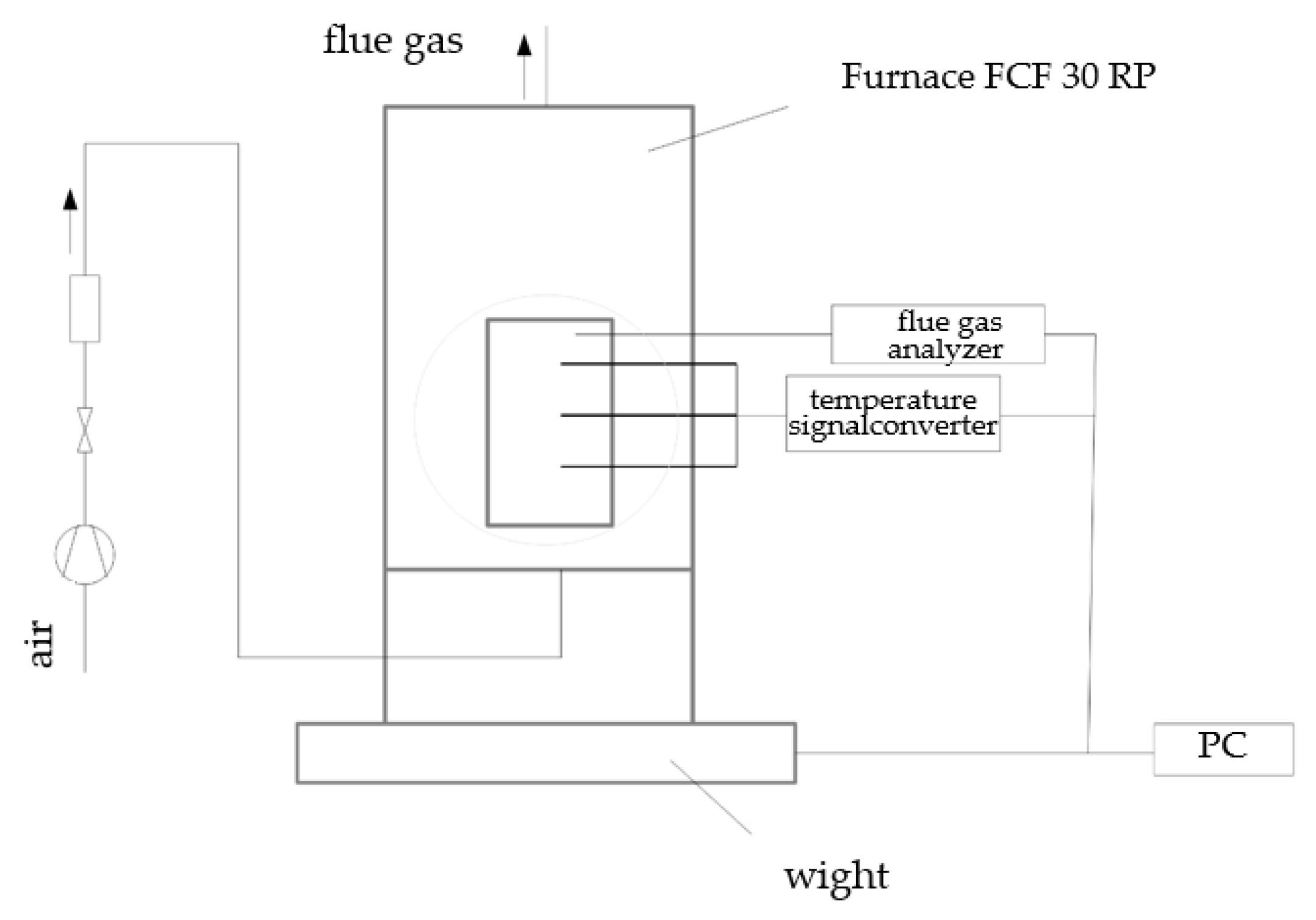
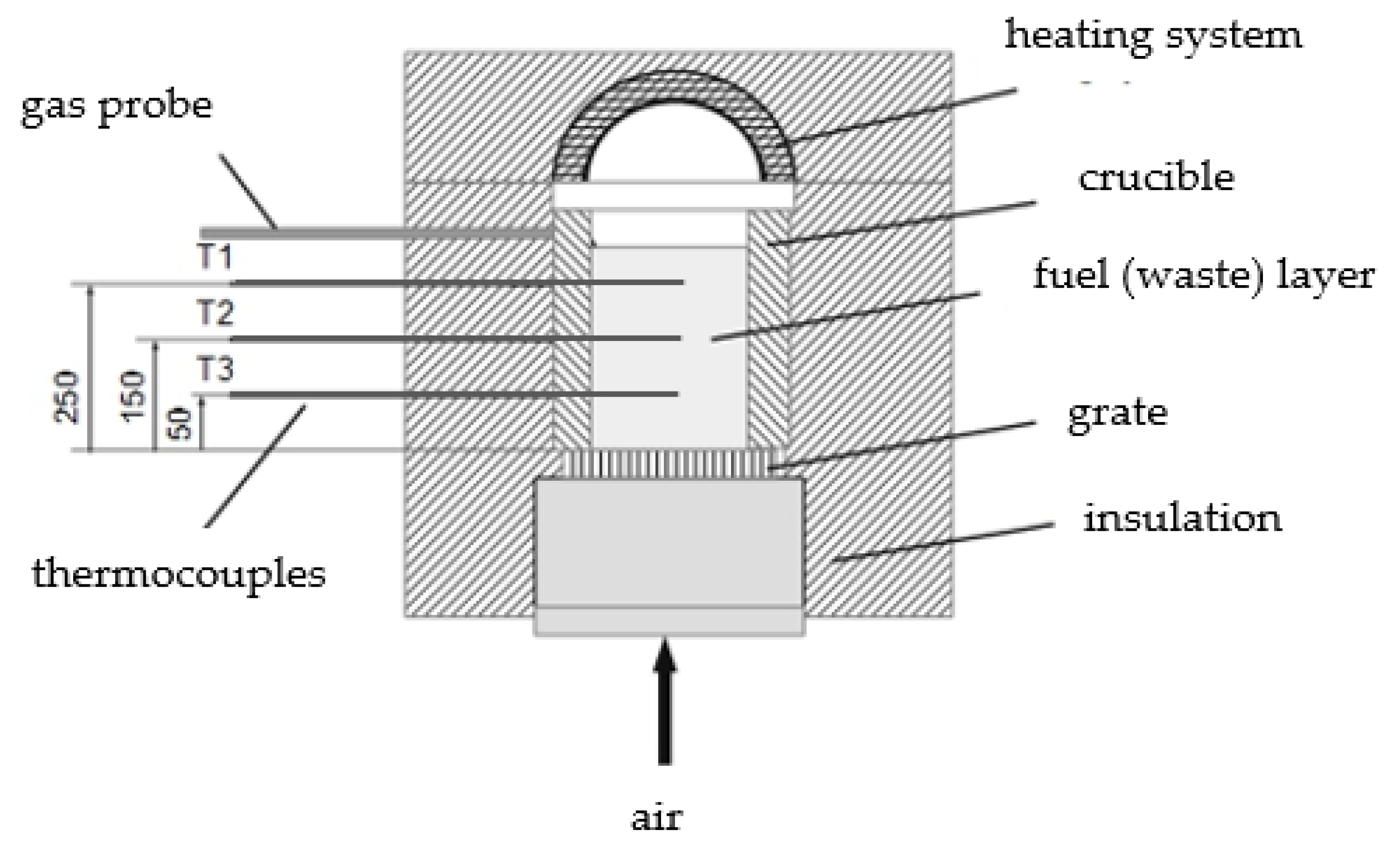
3. Methods of Testing the Similarity of the Combustion Process

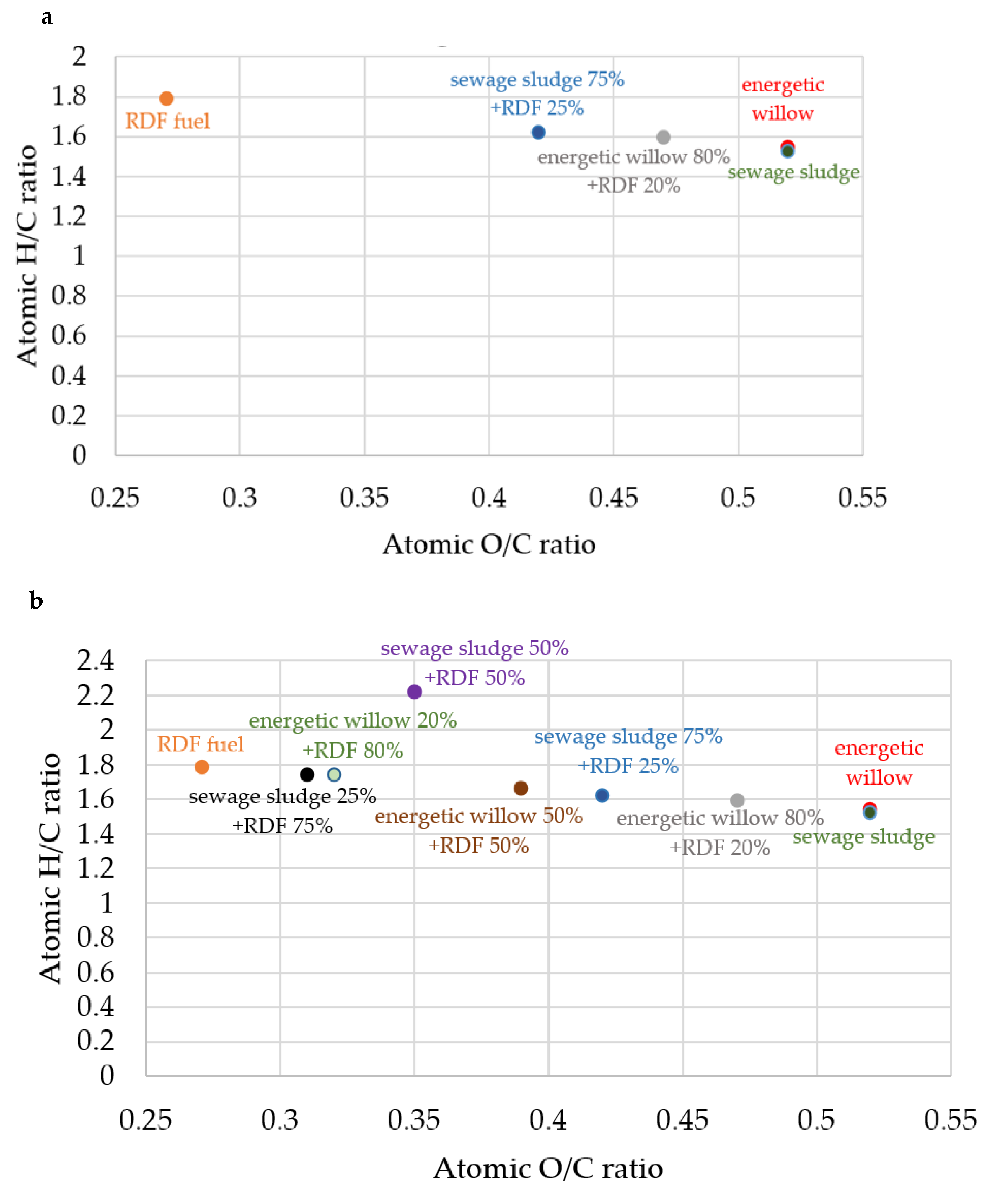
3.1. Diagram of Van Krevelen

Van Krevelen [32] presented classic fuels in a flat coordinate system, where the O/C atomic quotients were given on the abscissa x, and on the ordinates y = H/C (excluding N, S, P and microelements). Assuming carbon tetravalinity, the maximum ordinate value was 4 and the abscissa x = O/C ≤ 2. Meunieur [33] modified the Van Krevelen diagram by adopting the summary chemical formula CHyOx for these fuels (x, y-coordinates from the diagram). A modification of Meunieur gave a better picture of the chemical structure than the mass percentage of the elements C, H and O.
For selected renewable fuels, the image in the Van Krevelen systematics was determined. The goal was to demonstrate similarity as fuels by knowing the place of these fuels on the diagram and their energy suitability for conventional fuels.
To determine the fuel location on the Van Krevelen diagram, it was necessary to calculate the atomic quotients x and y for the dry organic matter of fuels excluding sulfur and phosphorus in accordance with condition (1) [34,35]:
C + N + O + H = 100%
where:
C, N, O, H—content of elements in the sample in % by weight.

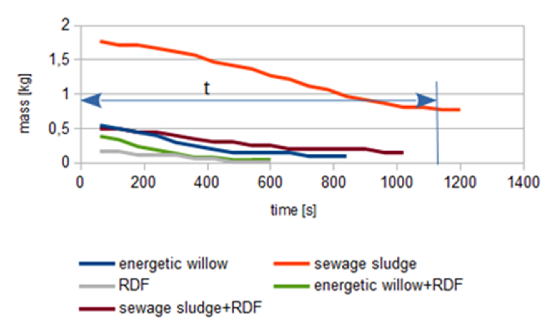
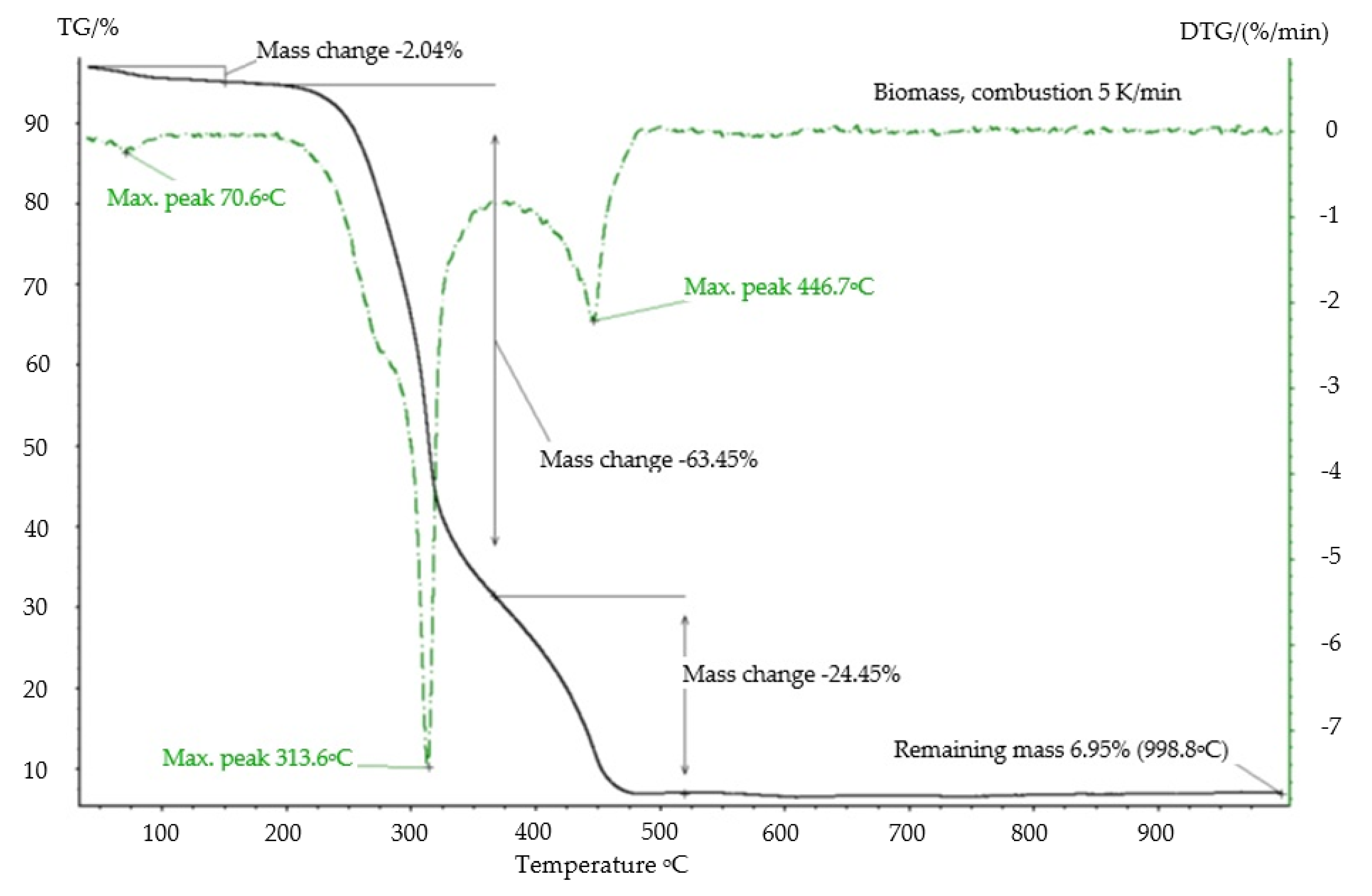
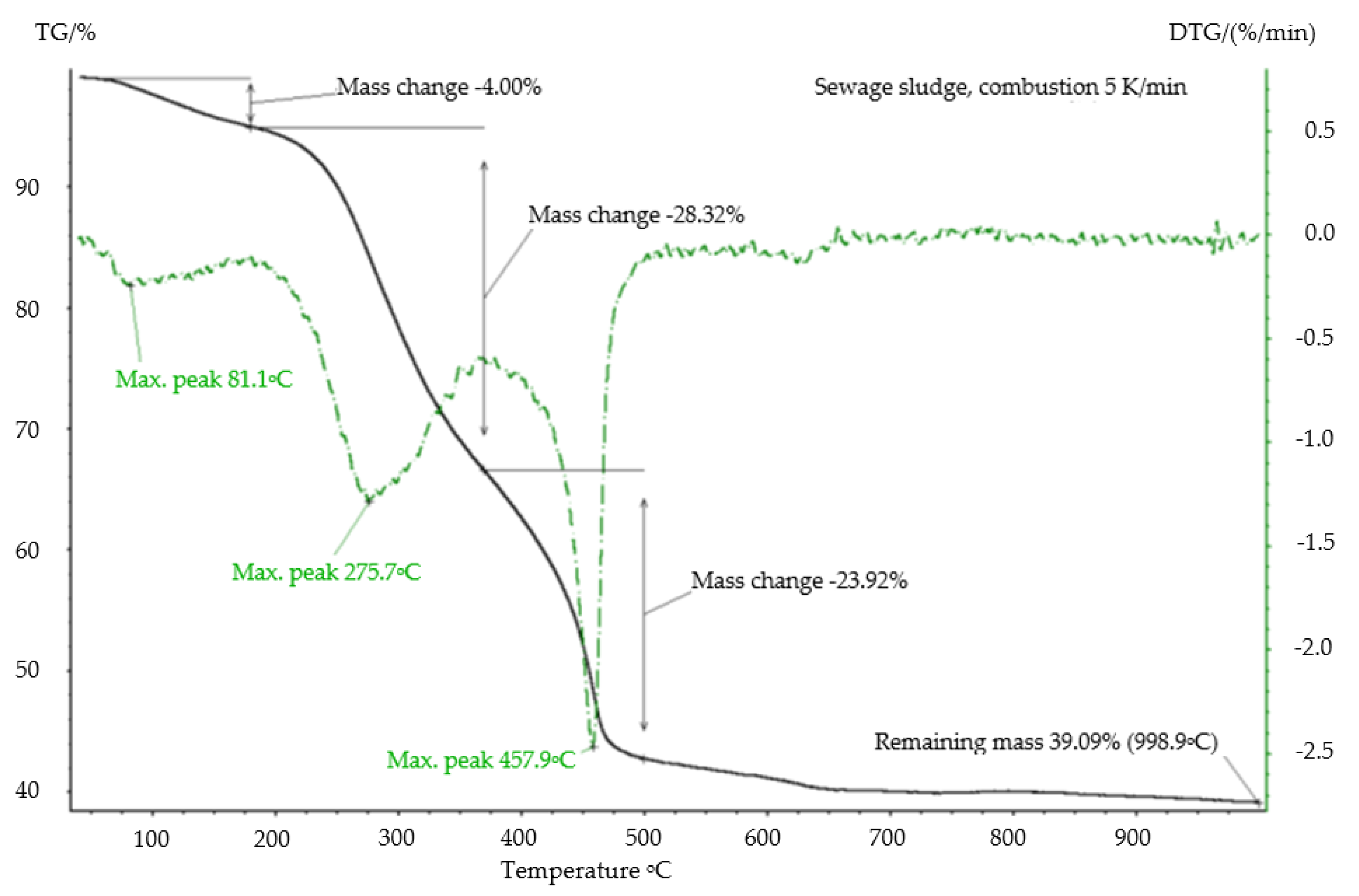
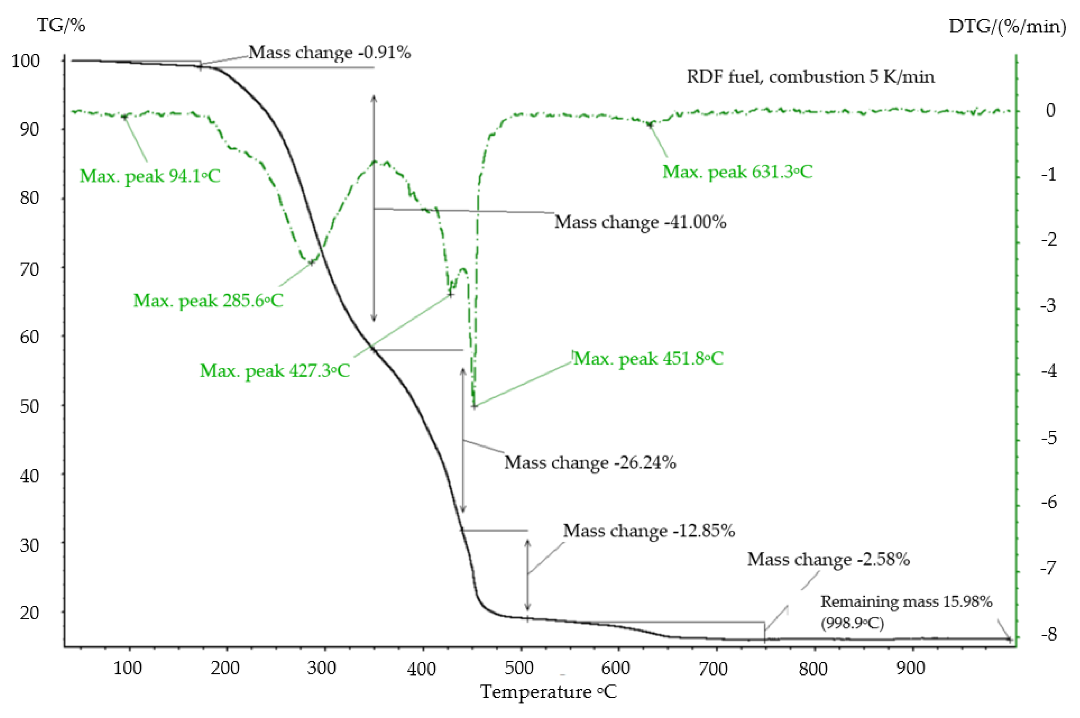
3.2. Thermogravimetric Analysis

A TG ((Thermogravimetry) and DTG (Derivative Thermogravimetric) analysis of samples marked “biomass (energetic willow), sewage sludge, RDF” were carried out using the Netzsch STA 409 PG Luxx thermogravimetric analyzer on a TG carrier coupled with a QMS Aeolos quadrupole mass spectrometer [36].
The tests were carried out in the atmosphere of argon (purity class 5.0, flow 25 mL/min) and synthetic air composed of 80% nitrogen and 20% oxygen (purity class 5.0, flow 50 mL/min), from 40 to 1000 °C, with a heating rate 5 K/min [36]. The choice of this heating rate resulted mainly from the need for a more precise identification of the fuel combustion kinetics on the TG and DTG graphs. The data for the heating rate of 20 K/min also do not bring radical changes to the course of the curves as above (the change applies only to the shorter duration of the weight loss course) The weight of the samples was 10 ± 0.1 mg.
The biomass sample was ground in a scissor mill to a grain size of less than 0.2 mm. The sewage sludge sample was ground in an agate mortar and passed through a 0.2 mm sieve. The RDF sample was ground in a cryogenic mill to a grain size of less than 0.2 mm. The tests were performed in crucibles of Al2O3 without a lid. The measurement was corrected by means of corrective measurements (measurement without sample). Corrective measurements were performed twice [36].

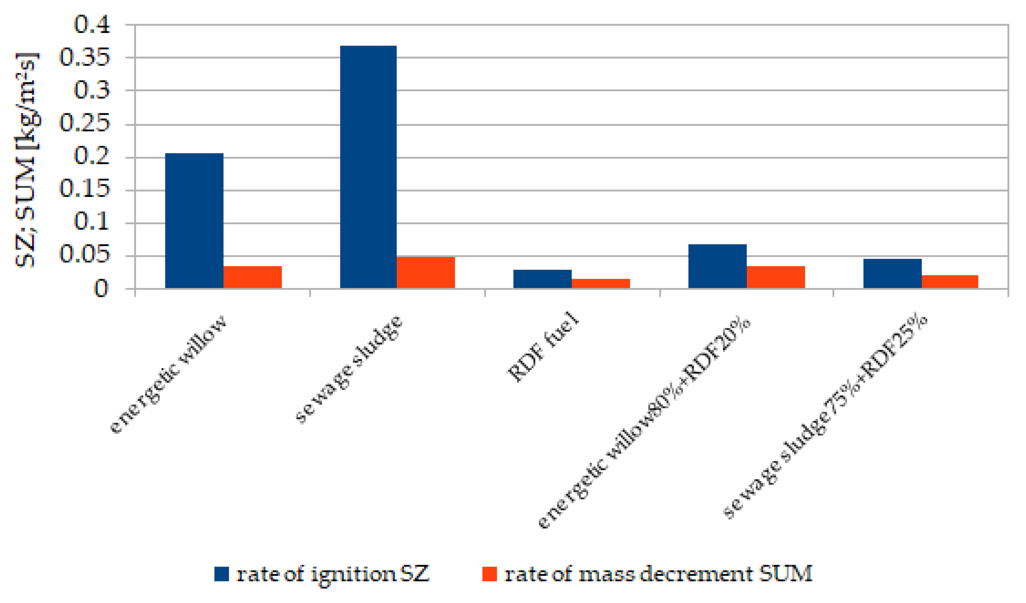
3.3. Indicators for the Quantitative Assessment of the Combustion Process

Five indicators for the quantitative assessment of combustion were defined and tested, i.e., reaction front rate, ignition rate, mass loss rate, thermal and mechanical load of grate.
A laboratory stand was used to determine the above indicators. An integral part of the stand is an electric chamber furnace, type FCF 30 RP, with a power of 5 kW, Figure 1. Apart from the furnace, the stand is equipped with a fan with combustion air supply ducts, and a chimney to remove exhaust gases. The main element of the furnace is the crucible for waste, the construction of which is shown in Figure 2. The crucible has been adapted to the combustion of a waste layer with a maximum height of 300 mm. The crucible has temperature sensors built up along its height, placed at distances: 50/150/250 mm from the grate surface, respectively. The stand was additionally equipped with a weighbridge that continuously controls the weight loss of incinerated waste.
The study determined the similarity of the combustion process of the biomass and solid waste fuel–RDF layer with a height of 300 mm by, in particular, measuring the temperature inside the incinerated waste layer (temperature sensors were placed in the axis of the fuel layer) at three heights of 50/150/250 mm and weight loss. The tests were carried out at 850 °C, as this temperature range is suggested in [16]. Efforts were made to ensure that the amount of air supplied for the combustion of samples was at a similar level—the excess air ratio λ was in the range of 2–3.5. The process time at the laboratory stand was determined and corrected as a result of several test repetitions for given samples until a satisfactory—similar for all samples—average air excess coefficient was obtained. All tested quantities were measured with a sampling frequency of 60 s. The analyses were carried out with a minimum of three replicates.
The obtained results allowed the calculation of indicators for the quantitative assessment of incinerated waste according to the formulas given below.
The first of these indicators is the rate of reaction front. This is the speed with which the combustion front proceeds in the waste layer on the stationary grate of the laboratory furnace (Figure 2) in a direction perpendicular to the grate. If we place temperature sensors along the height of the layer subjected to the combustion process on the grate (at certain distances from each other—ΔxFR [m]), then the maximum temperature increase (2) (manifested by the occurrence of the maximum temperature in a given thermocouple) gives the location of the reaction or flame front [37,38].
Δ ϑ Δ t = ( Δ ϑ Δ t ) max
The rate of the reaction front (uFR) can be determined by knowing the time Δt [s] that has elapsed since the occurrence of the temperature maximum between two adjacent thermocouples—Figure 3; the distance between them is Δx [m]—Equation (3) [37,38]:
u FR = Δ x FR Δ t [ m s ]
The credibility of the method for determining the speed of the reaction front depends on the number of thermocouples on the combustion front path (in our research methodology were three thermocouples, thus two independent data on the front speed were obtained in one measurement). Repeating the test several times and drawing the average from the measurements minimizes the error related to the heterogeneity of the combustion front.
The ignition rate (SZ) determines the fuel stream per time unit that ignites per unit area—Equation (4). This indicator allows to determine the waste stream during ignition on the grate per m2 of its area [37,38]:
SZ = u FR ρ n [ kg m 2 s ]
ρn—bulk density (kg/m3).
The rate of mass loss (SUM), determines the stream of mass loss per time and per unit of grate area—Equation (5) [37,38]:
SUM = Δ m fuel A R [ kg m 2 s ]
  • Δmfuel—the rate of fuel reduction (kg/s),
  • AR—area of the grate (m2).
The SUM strongly depends on the process time, and the greatest fuel loss is registered in the first part of the combustion phase—Figure 4. The time of this phase is the basis for calculating the fuel loss stream [37].
The thermal load of the grate (OCR), Equation (6), is an important issue from the point of view of the operation of grate waste incineration plants. The thermal load of the grate indicates the amount of energy released from the fuel during its oxidation per time and per certain area of the grate (it may determine the cooling method) [37].
OCR = SUM W d [ kW m 2 ]
Wd—calorific value of fuel (kJ/kg).
Observation of the thermal load indicator helps in the response of the technical service to, among other things, thermally overload the grate.
Mechanical load of the grate (OMR) (7):
OMR = ( m p t ) / A R [ kg m 2 h ]

4. Results and Discussion

In this section, the results of the research on the properties of flammable substances and the operational and construction parameters of grate furnaces adapted to coal combustion are discussed, along with an analysis of the possibility of adapting these furnaces to the combustion of alternative and renewable fuels in the form of energetic willow, sewage sludge and RDF in the following areas:
  • using the Van Krevelen diagram for a more effective comparison of the fuel characteristics of analyzed renewable and alternative fuels with coal;
  • tests on a microscale, i.e., thermogravimetric analysis, to identify the basic features of the TG/DTG combustion kinetics;
  • to characterize the usefulness of replacing coal with the tested substances and their mixtures in the grate furnaces by comparing the thermal and mass load capacity of the grates and testing the indicators of quantitative assessments of combustion.

4.1. Using the Van Krevelen Diagram for a More Effective Comparison of Fuel Characteristics

Although in the original version the Van Krevelen diagram was used to observe the transformation of substances to more carbonized forms due to anaerobic heating, in the case of this study, the authors use this method of conveying information as a comparison of the location of various combinations—mixtures of combustible substances in relation to areas in the graph minimizing the O/C and H/C. The location of the points characterizing the fuel properties of the tested materials as separate biomass substances, i.e., energetic willow and sewage sludge, as well as RDF indicates the greater energy potential of the last mentioned (low O/C ratio). Energetic willow and sewage sludge are close to the biomass coordinates. Improvement—lowering the O/C and H/C ratio can be obtained by drying or, for example, torrefactioning these substances before the combustion process.
In the diagram in Figure 5, a change in coordinates, improving the energy properties, is visible in the case of sewage sludge–RDF and energetic willow–RDF mixtures in the research variant (Section 2) and theoretically simulated variants of other mass components.

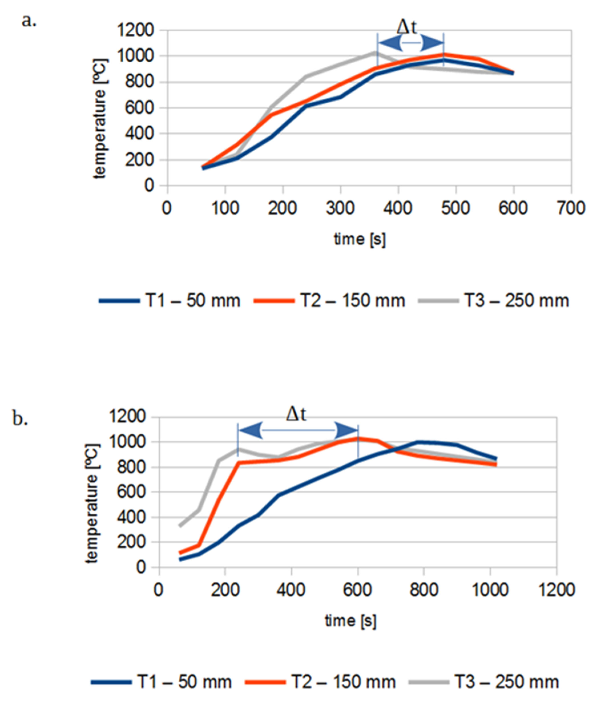
4.2. Thermogravimetry Studies to Identify the Basic Features of Combustion Kinetics

The analysis of Figure 6, Figure 7 and Figure 8 shows that the tested samples combustion was in several stages. In the first stage, starting from the room temperature of about 140–180 °C, the samples lose moisture. Combustion is divided into two stages in the case of energetic willow and sewage sludge, while for the RDF sample, four process stages can be distinguished. It can be assumed that in the first stage of combustion, degassing of the sample and combustion of the released gases mainly takes place, while in the second stage fixed carbon is incinerated. The values of mass loss in individual stages, the temperature of the maximum decomposition rate and the mass remaining after combustion can be read from the graphs for an exemplary tested heating rate. The results of TG and DTG analysis for energetic willow coincide with the results of similar studies in [31,39] and in the case of RDF and sewage sludge analysis in [29,40].
The mixtures of the fuels were not tested thermogravimetrically, assuming that a greater accuracy and use of the data to compare the combustion process on real grates will be carried out by laboratory-scale studies on mixture combustions (samples of about 1 kg).

4.3. Recommendations on Replacing Coal with Alternative and Renewable Fuels and Their Mixtures in the Existing Grate Furnaces of Boilers in Thermal Power Engineering

However, the most expected result of the research is undoubtedly the indication of a large similarity between the indicators of the quantitative assessment of the combustion of the tested fuels—in particular, the ignition rate and the weight loss rate. The values of these indicators are presented in Table 2 and graphically compared in Figure 9.
Pure biomass in the form of energetic willow or sewage sludge shows large differences in the ignition rate and the rate of weight loss. This can result in unburned biomass remaining at the end of the grate. RDF has a fairly good compliance regarding these indicators, but a very low mechanical and thermal load of the grate. Following the principle of minimizing the SZ/SUM ratio, fuel mixing brings improvement. A strong decrease in this ratio is already noted for mixtures (energetic willow–RDF and sewage sludge–RDF) with the share of the components as presented in Section 2. The reference values of the mechanical and thermal load of the three basic types of grates are presented in Table 3. Here, there is also an increase in the load of the grate, and, in particular, a thermal load can be achieved by creating fuel mixtures as previously described. With a mass ratio of energetic willow to RDF of 0.8:0.2, it is possible to improve this parameter by as much as 46% compared to pure RDF, and 9% compared to pure energetic willow. A similar tendency of the thermal load to increase occurs with sewage sludge mixtures with RDF. Therefore, it is possible to mix fuels in various proportions in compliance with the limit values given by grate manufacturers, which are presented in Table 3.

5. Conclusions

The search for biomass and waste fuels to replace solid, exhaustible conventional fuels, such as hard coal and lignite, is today an irreversible way of obtaining energy. This article presents a proposal of coal replacement with biomass substances—renewable and alternative—in the form of energetic willow (forest biomass) and sewage sludge. The choice was dictated by the availability of this biomass on a large scale, which could be of interest to the modernizing area of thermal power engineering, equipped with grate boilers with a capacity of 1 to 50 MW.
This research assessed the possibility of the combustion and co-combustion of biomass substrates (energetic willow/sewage sludge), in the light of the RES law, with fuel from waste, defined here as RDF. Particular interest in these fuels and their mixtures results from search by thermal power engineering sector for fuels whose combustion will be associated with benefits, e.g., the acquisition of energy origin licenses, availability and lower cost of obtaining fuel (RDF), as well as moderate investment contribution using the existing base of coal grate boilers. The article indicates possible variants of combustion and co-combustion of the abovementioned fuels, referring to the use of technical and technological capabilities of coal grate furnaces. It was possible by comparing: mechanical and thermal load of grates, as well as so-called indicators for the quantitative assessment of combustion (i.e., ignition rate and mass loss rate). The result of the combustion of the fuel as above in a laboratory-scale furnace (samples weighing up to 1 kg), as well as their thermogravimetric analysis, indicates a great similarity of the mass loss curve, temperature profiles and combustion phases, as well as indicators of quantitative assessments in the process of biomass and RDF oxidation.
The mechanical and thermal limit loads of different types of grates, important from the point of view of the operation of grate boilers, were analyzed. The obtained results of the mechanical and thermal load capacity of the grates are encouraging, which are the basis for further analyses of fuel replacement—i.e., comparing the results of the thermal load of the grate OCR with the mechanical load of the grate OMR in Table 2 with the values in Table 3, without the risk of failures, e.g., grate burnout, mechanical overload, and, from what is stated on the basis of the indicators of quantitative assessments of combustion, the combustion process of the tested fuels could be carried out while maintaining the quality of burning the fuel layer (ignition rate, mass loss rate), and here the data from Table 2 can also be compared. All the values of the tested samples were within the recommended load ranges. Additionally, the results of the tests on the mixtures of the substances in order to improve/increase, e.g., the bulk density, the ratio of the ignition rate to the rate of mass loss, and the mechanical and thermal load of the grate adjusted to its type are interesting.
One should not forget about an important feature—the analyzed fuels can replace each other. This is important in the case of temporary fluctuations in the availability of these fuels on the market.
Of course, in the case of RDF combustion, the furnace and installation should ensure that the conditions for carrying out the thermal waste conversion process specified in [16] are met.

Author Contributions

Conceptualization, T.J.J.; formal analysis, T.J.J.; writing, T.J.J. and M.K.-S.; methodology, T.J.J. and M.K.-S.; funding acquisition for research, T.J.J.; Investigation T.J.J. and M.K.-S.; Project administration M.K.-S.; Resources T.J.J. and M.K.-S. All authors have read and agreed to the published version of the manuscript.

Funding

Publication was funded by the InnoEnergy and by research subsidy allocated for 2020 (08/030/BK_20/0079).

Conflicts of Interest

The authors declare no conflict of interest.

Nomenclature

uFRreaction front rate, m/s
xFRlocation of reaction front, m
ttime of combustion, s
SZignition rate, kg/(m2s)
ρnbulk density, kg/m3
SUMthe rate of mass loss, kg/(m2s)
Argrate area, m2
Δmfuelthe mass loss over time, kg/s
OCRrate heat release rate, kW/m2
Wdcalorific value of the fuel, kJ/kg
OMRmechanical load of grate, kg/m2h
xposition of the waste on the grate, m
mpthe mass of fuel, kg

References

  1. EU. Dyrektywa Parlamentu Europejskiego i Rady (UE) 2018/2001 z dnia 11 Grudnia 2018 r. w Sprawie Promowania Stosowania Energii ze Źródeł Odnawialnych; EU: Brussels, Belgium, 2018. [Google Scholar]
  2. Rogowska, D. Wykorzystanie OZE w energetyce a zrównoważony rozwój. Nafta-Gaz 2017, 8, 616–623. [Google Scholar] [CrossRef]
  3. Bilgili, F.; Koçak, E.; Bulut, Ü.; Kuşkaya, S. Can biomass energy be an efficient policy tool for sustainable development? Renew. Sustain. Energy Rev. 2017, 71, 830–845. [Google Scholar] [CrossRef]
  4. Kotlicki, T.; Buchta, J. Co-firing of waste in power industry-analysis of legal conditions in Poland. J. Power Technol. 2011, 91, 165–170. [Google Scholar]
  5. Alwaeli, M. Recycling of packaging waste in Poland. Waste Manag. 2009, 29, 3054–3055. [Google Scholar] [CrossRef]
  6. Alwaeli, M. An economic analysis of joined costs and beneficial effects of waste recycling. Environ. Prot. Eng. 2011, 37, 91–103. [Google Scholar]
  7. Kicińska, A.; Gucwa, J.; Kosa-Burda, B. Evaluating potential for using municipal sewage sludge in the rehabilitation of ground degraded by the sodium processing industry. Bull. Environ. Contam. Toxicol. 2019, 102, 399–406. [Google Scholar] [CrossRef] [Green Version]
  8. Gaska, K.; Generowicz, A.; Lobur, M.; Jaworski, N.; Ciuła, J.; Vovk, M. Advanced algorithmic model for poly-optimization of biomass fuel production from separate combustible fractions of municipal wastes as a progress in improving energy efficiency of waste utilization. In Proceedings of the 2nd International Conference on Renewable Energy and Environment Engineering (REEE 2019), Munich, Germany, 19–22 August 2019; Caetano, N., Ed.; EDP Sciences: Les Ulis, France, 2019; Volume 122, p. 01004. [Google Scholar] [CrossRef]
  9. Kicińska, A. Chemical and mineral composition of fly ashes from home furnaces, and health and environmental risk related to their presence in the environment. Chemosphere 2019, 215, 574–585. [Google Scholar] [CrossRef]
  10. Krawczyk, P.; Szczygieł, J. Analiza uwarunkowań stosowania paliwa alternatywnego do wytwarzania energii elektrycznej i ciepła w warunkach przedsiębiorstwa ciepłowniczego (Refusederivedfuel as a fuel for chp plant in a heating plant conditions). Rynek Energii 2013, 6, 91–96. [Google Scholar]
  11. Ghisellini, P.; Cialani, C.; Ulgiati, S. A review on circular economy: The expected transition to a balanced interplay of environmental and economic systems. J. Clean. Prod. 2016, 114, 11–32. [Google Scholar] [CrossRef]
  12. Lewandowski, M. Designing the Business Models for Circular Economy—Towards the Conceptual Framework. Sustainability 2016, 8, 43. [Google Scholar] [CrossRef] [Green Version]
  13. Geissdoerfer, M.; Savaget, P.; Bocken, N.M.; Hultink, E.J. The Circular Economy—A new sustainability paradigm? J. Clean. Prod. 2017, 143, 757–768. [Google Scholar] [CrossRef] [Green Version]
  14. USTAWA, OOZE. Ustawa z dnia 20 lutego 2015 r. o odnawialnych źródłach energii. Dz.U. 2015, 478, 1–230. [Google Scholar]
  15. Energetyczne, P. Ustawa z dnia 10 kwietnia 1997 r.—Prawo energetyczne. Dz.U. 1997, 54, 348. [Google Scholar]
  16. ISAP. Rozporządzenie Ministra Rozwoju z dnia 21 stycznia 2016 r. w sprawie wymagań dotyczących prowadzenia procesu termicznego przekształcania odpadów oraz sposobów postępowania z odpadami powstałymi w wyniku tego procesu. Dz.U. 2016, 108, 1–3. [Google Scholar]
  17. Lin, H.; Ma, X. Simulation of co-incineration of sewage sludge with municipal solid waste in a grate furnace incinerator. Waste Manag. 2012, 32, 561–567. [Google Scholar] [CrossRef]
  18. Yang, Y.B.; Ryu, C.; Goodfellow, J.; NasserzadehSharifi, V.; Swithenbank, J. Modelling waste combustion in grate furnaces. Process. Safety Environ. Prot. 2004, 82, 208–222. [Google Scholar] [CrossRef]
  19. Bleckwehl, S.; Riegel, M.; Kolb, T.; Seifert, H. Kennzahlen zur Quantitativen Beschreibung des Abbrandes von Ersatzbrennstoffen; Herstellung und Verwertung, Thome-Kozmiensky, K.J., Beckmann, M., Eds.; Berliner Abfallwirtschaftskonf: Berlin, Germany, 2005; pp. 127–141. [Google Scholar]
  20. Bleckwehl, S.; Kolb, T.; Schröder, E.; Vortmann, C. Measurements and modelling of solid fuel combustion in fixed bed reactors. In Proceedings of the 30th International Symposium on Combustion, Chicago, IL, USA, 25–30 July 2004; pp. 25–30. [Google Scholar]
  21. Polesek-Karczewska, S.; Turzyński, T.; Kardaś, D.; Heda, Ł. Front velocity in the combustion of blends of poultry litter with straw. Fuel Process. Technol. 2018, 176, 301–315. [Google Scholar] [CrossRef]
  22. Kluska, J.; Turzyński, T.; Kardaś, D. Experimental tests of co-combustion of pelletized leather tannery wastes and hardwood pellets. Waste Manag. 2018, 79, 22–29. [Google Scholar] [CrossRef]
  23. Saeed, M.A.; Medina, C.H.; Andrews, G.E.; Phylaktou, H.N.; Slatter, D.; Gibbs, B.M. Agricultural waste pulverised biomass: MEC and flame speeds. J. Loss Prev. Process. Ind. 2015, 36, 308–317. [Google Scholar] [CrossRef]
  24. Fernandez-Anez, N.; Slatter, D.J.; Saeed, M.A.; Phylaktou, H.N.; Andrews, G.E.; Garcia-Torrent, J. Ignition sensitivity of solid fuel mixtures. Fuel 2018, 223, 451–461. [Google Scholar] [CrossRef]
  25. Kubica, K.; Ściążko, M.; Raińczak, J. Współspalanie biomasy z węglem. Polityka Energetyczna 2003, 6, 297–307. [Google Scholar]
  26. Golec, T. Współspalanie biomasy w kotłach energetycznych. Energetyka 2004, 7–8, 437–445. [Google Scholar]
  27. Haustein, E.; Grabarczyk, L. Wpływ współspalania biomasy z węglem kamiennym na wybrane właściwości fizyczno-chemiczne popiołu lotnego. Polityka Energetyczna 2012, 15, 87–101. [Google Scholar]
  28. Czop, M.; Kajda-Szcześniak, M. Tests of physicochemical properties of fuel and ballast fractions from waste processing installations. ACEE Archit. Civ. Eng. Environ. 2016, 9, 113–122. [Google Scholar] [CrossRef] [Green Version]
  29. Magdziarz, A.; Wilk, M. Thermogravimetric study of biomass, sewage sludge and coal combustion. Energy Convers. Manag. 2013, 75, 425–430. [Google Scholar] [CrossRef]
  30. Werther, J.; Ogada, T. Sewage sludge combustion. Prog. Energy Combust. Sci. 1999, 25, 55–116. [Google Scholar] [CrossRef]
  31. Kok, M.V.; Özgür, E. Thermal analysis and kinetics of biomass samples. Fuel Process. Technol. 2013, 106, 739–743. [Google Scholar] [CrossRef]
  32. Van Krevelen, D.W. Graphicalstatistical method for the study of structure and reaction processes of coal. Fuel 1950, 29, 269. [Google Scholar]
  33. Meunieur, J. Vergasung Fester Brennstoffe und die Oxidative Umwandlung von Kohlenwasserstoffen; Chemie: Weinheim, Germany, 1962. [Google Scholar]
  34. Ostojski, A. Sewage sludge classification based on elementary analysis. In Nowe metody redukcji emisji zanieczyszczeń i wykorzystnia produktów ubocznych oczyszczalni ścieków.—T. 4 H. Obarska-Pempkowiak; Pawłowski, L., Ed.; Komitet Inzynierii Środowiska PAN: Lublin, Poland, 2009; pp. 41–51. [Google Scholar]
  35. Kempa, E. Systematyka osadów ściekowych. In Materiały Międzynarodowej Konferencji Naukowo Technicznej ”Osady Ściekowe: Odpad czy Surowiec?”; Bień, J., Ed.; Politechniki Wrocławskiej: Częstochowa, Poland, 1997; pp. 7–35. [Google Scholar]
  36. Research Report No: ZMT/15/2019; ICHPW: Zabrze, Poland, 2019.
  37. Jaworski, T. Modelling of the Process of Mass Transfer on the Grates of Solid Waste Thermal Processing Equipment; Monograph Publisher Gliwice: Politechnika Śląska, Poland, 2012; pp. 132–142. [Google Scholar]
  38. Kajda-Szcześniak, M.; Jaworski, T. Characteristics of the combustion process of woodwork waste in the installation of thermal treatment of municipal solid waste (tpok). Wood Res. 2018, 63, 15–23. [Google Scholar]
  39. Red Ściążko, M. Kinetyka Reakcji Heterogenicznych w Procesach Konwersji Paliw Stałych; WIChPW: Zabrze, Poland, 2015. [Google Scholar]
  40. Król, D.; Poskrobko, S. Waste and fuels from waste Part, I. Analysis of thermal decomposition. J. Therm. Anal. Calorim. 2012, 109, 619–628. [Google Scholar] [CrossRef]
Figure 1. Schematic of the laboratory stand for the assessment of the fuel combustion process [37,38].
Sustainability 12 07894 g001
Figure 2. The grate-crucible for waste combustion with measuring equipment (made by Kajda-Szcześniak).
Sustainability 12 07894 g002
Figure 3. The temperature changes in the layer. (a) Energetic willow + fuel from waste (RDF). (b) Sewage sludge + RDF.
Sustainability 12 07894 g003
Figure 4. Decrement of mass of selected sample in time of combustion.
Sustainability 12 07894 g004
Figure 5. (a) Illustration of the position of tested samples of biomass and solid waste fuels in the Van Krevelen diagram. (b) Improvement of coordinates with simulated mass fractions (fractions of ingredients in mixtures determined at the coordinate).
Sustainability 12 07894 g005
Figure 6. TG and DTG curves of combustion 5 K/min of biomass (energetic willow) [36].
Sustainability 12 07894 g006
Figure 7. TG and DTG curves of combustion 5 K/min of sewage sludge [36].
Sustainability 12 07894 g007
Figure 8. TG and DTG curves of combustion 5 K/min of RDF fuel [36].
Sustainability 12 07894 g008
Figure 9. The comparison of the rate of ignition and the rate of burning mass decrement.
Sustainability 12 07894 g009
Table 1. Physicochemical properties of samples.
Parameter Energetic
Willow
Sewage
Sludge
RDF
Fuel
Energetic Willow 80% + RDF 20%Sewage Sludge 75% + RDF 25%Hard Coal [25,26,27]
Total moisture, % mass7.11 ± 0.0479.58 ± 0.0726.23 ± 0.0610.93 ± 0.0466.24 ± 0.0719
Combustible fraction, % dry mass98.87 ± 0.1661.85 ± 0.0487.93 ± 0.2896.68 ± 0.1968.37 ± 0.190–95
Ash, % dry mass1.13 ± 0.1638.15 ± 0.0412.07 ± 0.283.32 ± 0.1931.61 ± 0.15–10
Volatile fraction, % dry mass81.98 ± 0.0252.6 ± 0.4385.65 ± 0.6582.71 ± 0.1560.86 ± 0.4818.49
High Heating Value, kJ/kg19,414.86 ± 22856.55 ± 3019,719.99 ± 2419,475.89 ± 67072.41 ± 2821–32
High Heating Value, kJ/kgdry mass20,900.92 ± 213,989.37 ± 3026,731.73 ± 2422,067.08 ± 61714.96 ± 28n.d.
Low Heating Value, kJ/kgdry mass19,352.30 ± 213,123.12 ± 3024,840.97 ± 2420,450.03 ± 616,052.58 ± 2822
Carbon, % dry mass53.38 ± 0.0530.38 ± 0.0456.44 ± 0.0653.99 ± 0.0536.90 ± 0.0587.52
Hydrogen, % dry mass6.88 ± 0.053.85 ± 0.048.4 ± 0.067.18 ± 0.054.99 ± 0.054.26
Oxygen, % dry mass37.04 ± 0.0421.15 ± 0.0620.37 ± 0.0533.70 ± 0.0520.96 ± 0.061.55
Nitrogen, % dry mass1.24 ± 0.094.86 ± 0.161.53 ± 0.071.30 ± 0.094.03 ± 0.141.25
Sulphur, % dry mass0.24 ± 0.021.47 ± 0.020.84 ± 0.070.36 ± 0.031.31 ± 0.030.3–1.5
Chloride, % dry mass0.09 ± 0.010.14 ± 0.020.35 ± 0.010.14 ± 0.010.19 ± 0.020.04–0.4
Table 2. The quantitative indicators of combustion process.
SampleUnit Energetic WillowSewage SludgeRDF FuelRDF FuelEnergetic Willow + RDF in Mass Share: 0.8/0.2Sewage Sludge + RDF in Mass Share: 0.75/0.25
12345678
Process
temp.
T
°C850850850850850850
Mass
mp
kg0.551.770.1720.1050.390.50
Layer height
h
m0.30.30.30.30.30.3
Combustion time ts90011406006006001020
Fuel stream
mp/t
kg/s0.00060.00150.000280.000170.000650.00049
λ-2.52.22.02.93.53.3
Bulk
density
ρn
kg/m3124369362283104
Rate of reaction front
uFR
m/s0.001660.000990.000830.000550.000830.00044
Rate of ignition
SZ
kg/m2 s0.20580.36890.029980.02120.069140.0462
Rate of mass decrement
SUM
kg/m2 s0.036050.049340.01560.01040.036460.0214
Thermal load of the grate
OCR
kW/m2697647417278759354
Mechanical load of the grate
OMR
kg/m2 h91.6232.94326.2597.573.53
SZ/SUM-5.703.941.922.031.892.15
Table 3. Limit values of the thermal and mechanical load of grate (own study).
Type of GrateMechanical Load of Grate kg/m2 hThermal Load of Grate kW/m2
Sliding grate80–120600–800
Moving grate 300–400700–1000
Reciprocating grate (Martin)700–8001500–2000

