Multi-Port DC-DC and DC-AC Converters for Large-Scale Integration of Renewable Power Generation


1
Renewable Energy Research Group and Department of Electrical and Computer Engineering, Faculty of Engineering, King Abdulaziz University, Jeddah 21589, Saudi Arabia
2
NEOM.com, An Nakheel, Riyadh 11564, Saudi Arabia
*
Author to whom correspondence should be addressed.
Sustainability 2020, 12(20), 8440; https://0-doi-org.brum.beds.ac.uk/10.3390/su12208440
Submission received: 24 August 2020
/
Revised: 5 October 2020
/
Accepted: 6 October 2020
/
Published: 13 October 2020
(This article belongs to the Special Issue Integration and Control of Renewable Energy and Power Electronics for Future Power Systems)
Abstract
:Numerous research studies on high capacity DC-DC converters have been put forward in recent years, targeting multi-terminal medium-voltage direct current (MVDC) and high-voltage direct current (HVDC) systems, in which renewable power plants can be integrated at both medium-voltage (MV) and high-voltage (HV) DC and AC terminals; hence, leading to complex hybrid AC-DC systems. Multi-port converters (MPCs) offer the means to promote and accelerate renewable energy and smart grids applications due to their increased control flexibilities. In this paper, a family of MPCs is proposed in order to act as a hybrid hub at critical nodes of complex multi-terminal MVDC and HVDC grids. The proposed MPCs provide several controllable DC voltages from constant or variable DC or AC voltage sources. The theoretical analysis and operation scenarios of the proposed MPC are discussed and validated with the aid of MATLAB-SIMULINK simulations, and further corroborated using experimental results from scale down prototype. Theoretical analysis and discussions, quantitative simulations, and experimental results show that the MPCs offer high degree of control flexibilities during normal operation, including the capacity to reroute active or DC power flow between any arbitrary AC and DC terminals, and through a particular sub-converter with sufficient precision. Critical discussions of the experimental results conclude that the DC fault responses of the MPCs vary with the topology of the converter adopted in the sub-converters. It has been established that a DC fault at high-voltage DC terminal exposes sub-converters 1 and 2 to extremely high currents; therefore, converters with DC fault current control capability are required to decouple the healthy sub-converters from the faulted one and their respective fault dynamics. On the other hand, a DC fault at the low-voltage DC terminal exposes the healthy upper sub-converter to excessive voltage stresses; therefore, sub-converters with bipolar cells, which possess the capacity for controlled operation with variable and reduced DC voltage over wide range are required. In both fault causes, continued operation without interruption to power flow during DC fault is not possible due to excessive over-current or over-voltage during fault period; however, it is possible to minimize the interruption. The above findings and contributions of this work have been further elaborated in the conclusions.
1. Introduction
The advantages of using DC grids and power electronic components in the renewable energy revolution are substantially identified [1,2,3,4,5,6,7,8,9]. However, with the dramatic increase of renewable energy penetration in power networks, DC grids need to be modified accordingly and require technologies such as DC-DC converters to meet the challenges posed by the intermittent nature of such energy sources [10,11,12,13,14]. As AC transformers in high-voltage alternating current (HVAC) grids, high-power DC-DC converters are essential for practical realization and effective operation of medium-voltage direct current (MVDC) and high-voltage direct current (HVDC) grids, which in this context aim to facilitate large-scale renewable energy generation [15,16]. Efficiency and reliability are paramount in high-power applications; therefore, DC-DC converters for MVDC and HVDC grids are expected to meet such requirements [15,17,18]. There are many topologies of high-power DC-DC converters proposed in the literature, and few were discussed in [16,17].
In the last five years, multi-port converters (MPCs) in MTDC grids have drawn significant research attention due to their unmatchable control performance, which is critical in renewable power applications integrated into AC and DC grids [15,19,20,21]. Multi-terminal DC networks provide the main platforms for realization of future super girds, in which large powers can be exchanged between networks dispersed over wide geographical areas, particularly those with large renewable energy-based power plants such as wind and solar photovoltaic [1,22,23]. Such MTDC networks are expected to be comprised of several DC voltage levels just like traditional AC power networks. The DC voltage level of each segment of such MTDC networks will be set according to its power handling capacity and the thermal limits of the DC cables. In addition, DC- DC converters in MTDC networks are expected to provide versatile functions and high performance, which include bidirectional power flow with low power losses, DC voltage control, DC fault isolation, and DC voltage matching and tapping (connection of DC systems with different DC voltages and grounding arrangements) [24,25,26,27,28].
In MTDC grids, various isolated and non-isolated modular multilevel DC-DC converters were proposed in recent years [29,30,31,32,33,34,35,36,37,38,39,40]. Most of the existing isolated DC-DC converters have adopted the basic structure of the dual active bridge (DAB) or front to front (F2F) connected DC/DC converter, which consists of two AC/DC converters, and their AC sides are connected together through an AC transformer. These DC-DC converters prevent DC fault propagation outside the affected DC side, and this helps in minimizing the number of DC circuit breakers and divides large MTDC networks into a number of isolated zones. However, the main disadvantage of the F2F DC-DC converters is that their high voltage and low voltage converters and the internal AC transformer must be rated at full power, 1.0 p.u., and their passive and active components are exposed to the full load currents. This leads to higher power loss and reduced overall efficiency.
In [28], the F2F DC-DC converters based on multilevel converter (MMC) was operated in a quasi-two level (Q2L) mode to reduce the size, weight, and cost. In this mode, the AC link of the F2F-MMC based DC-DC converter has a quasi-square waveform, with the isolating transformer subjected to a low and controllable dv/dt. It also helps in decreasing the current ratings of the semiconductor switches connected in series with the cell capacitors of the half-bridge cells and reducing the submodule capacitance and arm inductance. The transition arm converter (TAC), where some of the submodules in the lower arm of the MMC-based F2F DC-DC converter are replaced by series connected self-commuted devices, was discussed in [19,36] for further decreasing the capital cost and footprint and losses compared to that of the conventional MMC.
To decrease DC-DC converters size, weight, cost, and power losses, many researchers have advocated the non-isolated MMC-based F2F DC-DC converters as alternative to isolated type. Notwithstanding that the non-isolated DC-DC converter can hold the effect of pole to pole DC faults within the faulty DC side, it is incapable to hold the effect of the pole to ground faults [15].
In [37], a partially isolated modular DC transformer named auto-transformer was proposed, with the partial ability to block DC faults, and its main features are that the semiconductor switches of the low voltage side and isolation transformer that links upper and lower sub-converters do not experience the full load currents when the rated power is being exchanged between the high and low voltage sides. Many variants of this auto DC transformer, including front to front and multi pole models, to connect different HVDC transmission topologies, are discussed in [37]. Contrarily, the wide potentials exist in these DC-DC converters and their control methods are not fully explained.
The asymmetrical monopole configurations of the upper sub-converter and the lower sub-converter make the DC-DC converter in [37] subjected to high DC fault currents; particularly, any DC fault that may happen in the DC side will appear as a pole to pole DC short circuit fault. For instance, a pole to ground DC short circuit fault in the positive pole or in the negative pole makes a short circuit fault across the upper sub-converter or the lower sub-converter correspondingly.
Several non-isolated buck and boost hybrid cascaded DC-DC converters for HVDC transmission are proposed in [39]. In order to provide any required DC voltage magnitude from a fixed DC input voltage, the full-bridge (FB) cells in each limb are used to filter out the injected AC components. One of the main advantages of the presented hybrid cascaded DC-DC converters in [39] is that they do not require AC transformers compared to those presented in [37] and this leads to significant reduction in weight and cost. However, the major shortcoming of the presented converters in [39] is that the series switches and FB chain link of each limb must be designed to withstand the full rated DC link voltage of the HV side when a DC short circuit fault occurs at the low voltage side. This is considered as the main drawback of these converters since the power losses increase and affect the system efficiency.
In this paper, the concept of auto DC transformer presented in [37] is further developed to a generic MPC, in which a number of controllable DC and AC outputs are provided from a fixed or variable DC or AC voltage source. The generalized MPC presented in this paper resembles a cost-effective solution MPC for hybrid hubs, particularly, from the standpoint of DC voltage matching and power control in future DC grids. The theoretical basis that underpins the working principles of the presented MPC is explored, and further supported quantitatively by aid simulations, and corroborated experimentally, considering various operating conditions.
2. Multi-Port Converter
2.1. Fundamentals and Basic Theoretical Analysis
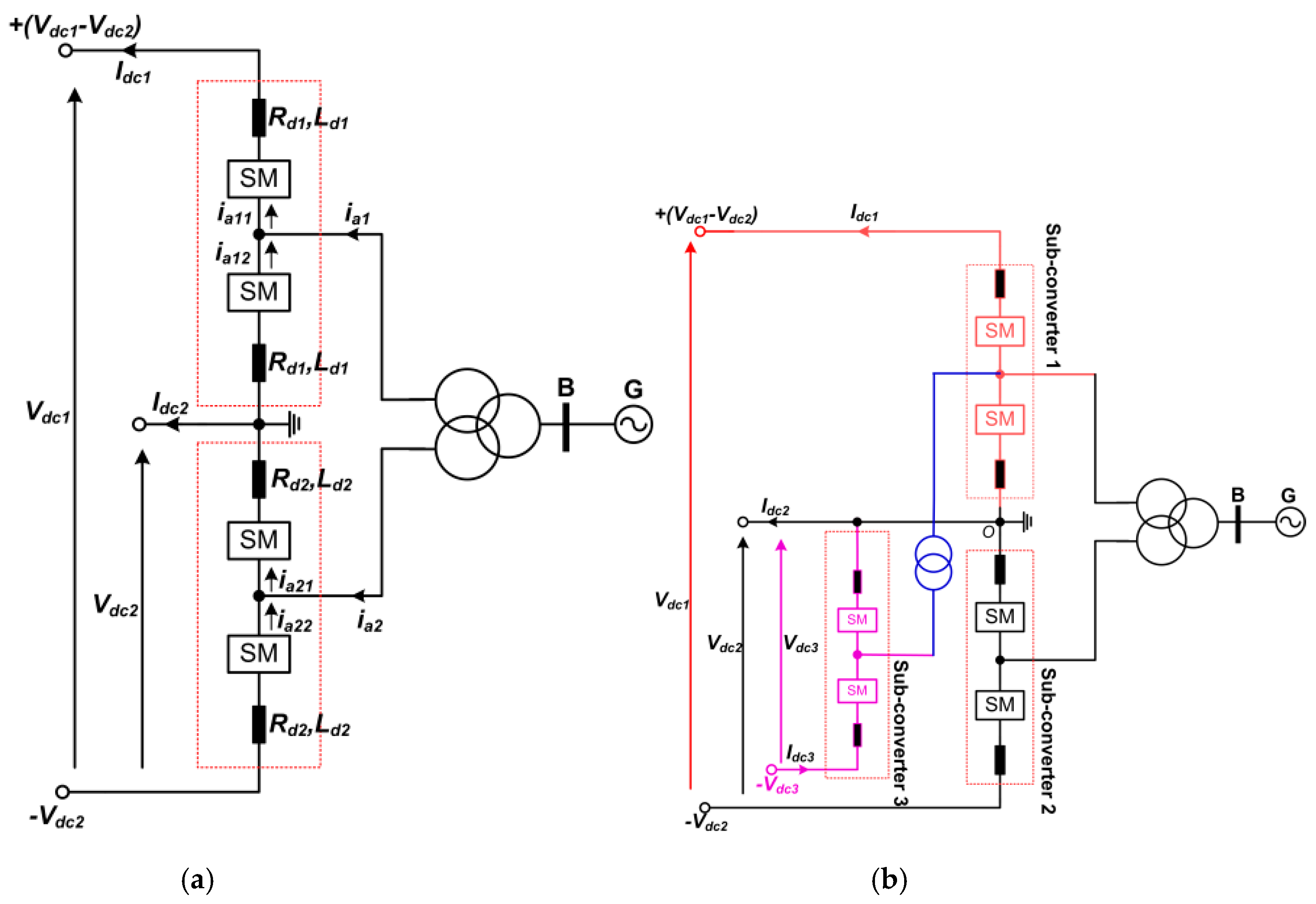
A number of MPCs that can be used for large-scale renewable power generation into MVDC and HVDC grids are illustrated in Figure 1. These MPCs can also be used as hybrid hubs with multitudes of controllable DC and AC outputs to control DC voltage and power as well as enable DC voltage matching and tapping. The DC voltage ratio and the power flow direction affect the current stresses in the semiconductor switches of sub-converters 1 and 2. Meanwhile, if the number of ports increases, the current stress in the semiconductor switches decrease. For an example, when the power flow indicated by the DC current directions in Figure 1a is positive, the real power exchanged between the upper and lower sub-converters via the AC side can be expressed as:
where Id1 and Id2 are DC currents in the upper and lower sub-converter arms respectively, Id1 = ⅓Idc1, and Idc2 = 3(Id2 − Id1) ≈ 3Id2 − Idc1, δ1; δ2 are the load angles between the terminal voltages of sub-converters 1 and 2; φ1 and φ1 are the phase shifts between the grid voltages and currents; Vm1 and Vm2, are the peaks of the terminal voltages across the upper and lower sub-converters 1 and 2, respectively; and Im1 and Im2 are the phase currents of sub-converters 1 and 2. Notice that, Idc2 denotes the mismatch between the DC currents of the upper and lower sub-converters, Id1 and Id2, as shown in Figure 1a, and Pac1 can be expressed as:
where n = Vdc1/Vdc2 and Pdc1 = Vdc1Idc1. The total real power exchange between the sub-converters and the AC grid is illustrated in Figure 1a, where Pg represents the algebraic summation of the AC powers of sub-converters 1 and 2, Pg = Pac1 + Pac2. The peaks of the terminal voltages across the AC side of the upper and lower sub-converters are given by:
Pac1 = 1.5Vm1Im1cos(δ1 + φ1) = 3(Vdc1 − Vdc2)Id1
Pac2 = 1.5Vm2Im2cos(δ2 + φ2) = 3Vdc2Id2
Pac2 = 1.5Vm2Im2cos(δ2 + φ2) = 3Vdc2Id2
Vm1 = ½m1(Vdc1 − Vdc2)
Vm2 = ½m2Vdc2
The current associated with the real power transfer between the AC and DC sides of the upper and lower sub-converters are:
The transformer windings and semiconductor switches of the lower sub-converter 2 encounter more current stresses than that in the upper sub-converter 1 when the power flow direction in both sub-converters are in the same directions, from DC to AC side or from AC to DC side.
Id1 = ⅓|Idc1|
Id2 = ⅓|Idc1| + ⅓|Idc2|
If the power flow direction in the upper sub-converter 1 opposes that in the lower sub-converter 2 and vice versa, the average DC currents in the sub-converters’ arms can be expressed as Id1 = ⅓|Idc1| and Id2 = ⅓|Idc1| − ⅓|Idc2|. The magnitude of the active currents related with real powers in the interfacing transformer windings of both sub-converters 1 and 2 are:
The above discussions reveal that the interfacing transformer windings and the semiconductor switches of sub-converter 2 experience lower current stresses when the power flow direction in the upper sub-converter 1 opposes that in the lower sub-converter 2. Therefore, the real power exchange between the upper and lower sub-converters through the AC side can be expressed as:
Vdc2||Idc1| − |Idc2||
When both AC and DC sides of the MPC displayed in Figure 1a are connected to live AC and DC networks, the real powers of upper and lower sub-converters Pac1 and Pac2 can be controlled independently of n and the current stresses on the lower sub-converter can be minimized. This happens because Pdc12 represents the DC power transferred between both upper and lower sub-converters via their arms, without crossing through the AC side as:
Pdc12 ≈ Pdc1/n ≈ Pac1/(n − 1)
Whereas, Pac2 determines the magnitude of DC power Pdc2 of the lower sub-converter 2 and its current stresses. Therefore, the sub-converter arms supply the net DC power needed at the DC side of the lower sub-converter 2 (Pdc2) with no AC power (Pac2 = 0) and zero current stresses on its switches, provided that the ratio n is high enough to avoid overstressing the semiconductor switches of the upper sub-converter 1.
Figure 1b illustrates three-port converter as an example of multi-port converter, which provides access to multiple DC voltage levels and ensures that currents are shared between the sub-converters. As shown in Figure 1b, sub-converters 1 and 2 exchange power between their DC and AC sides using theoretical basis as the two-port converter discussed above. On the other hand, the sub-converter 3 transfers real power through its AC link only. This indicates that the sub-converter 3 will share the AC power that sub-converter 1 provides to its AC side with the sub-converter 2. This leads to a reduction in the current stresses in the sub-converter 2 when the MPC operates as an auto transformer with no direct link to AC grid. In this manner, when sub-converter 1 supplies AC power and the other sub-converters 2 and 3 are sink power, the amount of AC power to be exchanged with the sub-converter 2 is given by
Pac2 = Pac1 − Pac3
Determining the AC power in sub-converter 1 is sufficient to define the net DC power (Pdc1) at HV DC terminal Pdc1 = nPac1(n − 1), and it is also enough to determine the value of DC power to be exchanged between sub-converters 1 and 2 without crossing through the AC side (Pdc1/n).
When the AC side of the MPC shown in Figure 1b is connected to the AC network, the DC power of sub-converter 2 is determined by the AC powers of sub-converter 1 and 2, i.e., Pac1 and Pac2. The AC power of sub-converter 1 determining the power exchange from sub-converters 1 to 2, while the AC power of sub-converter 2 determining the power flow from the AC side of sub-converter 2 to its DC side, is expressed as:
Pdc2 ≈ Pdc1/n + Pac2 ≈ Pac1/(n − 1) + Pac2
However, the DC power of the sub-converter 3 is defined independently by its AC power Pac3. The multi-port converters shown in Figure 1 can be designed by using various topologies such as two-level converter [41], half-bridge or full-bridge modular multilevel converter, and mixed cells MMC in sub-converters 1, 2, and 3. For instance, to model a multi-port converter to be used in medium-scale renewable integration, a two-level converter in the sub-converter 3 is sufficient. However, using different topologies in the sub-converters depends on the required operation characteristics.
2.2. Basis of Control System
When the AC side of the MPC in Figure 1a is linked to an active AC network, the power flow between AC and DC sides is regulated by controlling the magnitude and phase of the AC voltages of sub-converters with respect to the AC grid voltage. The difference between the phase angles, δ1 − δ2, of the terminal AC voltages of the sub-converters defines the magnitude and direction of the real power flow Pac2 to be transferred between sub-converters 1 and 2 through the AC side. Meanwhile, the exchanged DC power between sub-converters 1 and 2 without crossing the AC side can be determined by Idc1Vdc2 = Idc1Vdc1/n = Pdc1/n. The load angles also contribute in determining how much power is being transferred; for example, when δ1 + δ2 = 0, there is no power delivered to the AC grid. This means that the AC power of sub-converter 1 is sent to the sub-converter 2, i.e., Pac2 = −Pac1, where Pac1 = Pdc1(n − 1)/n and Idc2 = nIdc1), similar to the operation of DC auto transformer discussed above. The total AC powers of sub-converters 1 and 2 will be sent to the AC grid when δ1 − δ2 = 0, and there will be no power exchanged between these sub-converters. However, this does not mean there is no power transfer via the DC side. The aforementioned explanations indicate that the sub-converters of the multi-port converter under investigation can be regulated separately. Another case to discuss is when the AC side of the two-port converter is connected to a passive load, sub-converters 1 or 2 should control the AC voltage and the other must regulate the active power exchanged or the DC voltage. Recall that setting the value of Pac1 is sufficient to determine the DC power of the high voltage DC terminal, Pdc1 = nPac1/(n − 1) and DC link current Idc1 = Pdc1/Vdc1 = n/(n − 1) × Pac1/Vdc1.
When the direction of the power flow of the sub-converters opposes each other and AC power of sub-converter 1 is greater than that in sub-converter 2, Pac2 will determine the power exchanged between both sub-converters 1 and 2 through the AC side and the power injected to the AC network, Pg = Pac1 + Pac2. In the second scenario, when the AC power of sub-converter 2 is greater than that in sub-converter 1, Pac1 will define the power exchanged between both sub-converters through the AC side and the power injected to the AC network grid |Pac1 − Pac2|. No power is exchanged between both sub-converters if they have the same power flow direction, and this leads to zero power to be transferred between these sub-converters through AC side; also, the total power transfer will only be through the DC side, individual sub-converters, and the AC network.
When considering a three-windings transformer model as illustrated in Figure 1a, sub-converters 1 and 2 of the two-port converter can be expressed by the basic differential equations with reference to the secondary and tertiary sides as:
where RT1 = ½Rd1 + Rs + Rps and RT2 = ½Rd2 + Rt + Rpt are equivalent series resistances referred to as the secondary and tertiary sides, LT1 = ½Ld1 + Ls + Lps and LT2 = ½Ld2 + Lt + Lpt stand for the equivalent transformer inductances referred to secondary and tertiary sides; Rps and Rpt, and Lps and Lpt are the transformer primary windings resistance and inductance referred to secondary and tertiary sides; and Rs and Rt, and Ls and Lt are resistances and inductances of the secondary and tertiary windings. The DC components ½(Vdc1 − Vdc2) and ½Vdc2 cancel in line-to-line voltages that sub-converters 1 and 2 present to the secondary and tertiary sides of the interfacing transformer; thus, do not drive zero sequence currents. However, they appear as additional stresses, which increase the insulation requirements on the secondary and tertiary windings of the interfacing transformer. Recall that and . The sub-converter DC free terminal voltages can be defined in terms of their corresponding upper and lower arm voltages: and ; with these considerations, the d-q forms of the basic differential equations in (15) are expressed as:
From Equation (16), two independent current controllers are required for sub-converters 1 and 2 of the MPC illustrated in Figure 1a. The current controllers included in both sub-converters control systems are designed as:
Consequently, and , can be determined by the outer loops that control direct axis voltage in islanding operation scenario or active power or DC voltage in grid following mode. The outer loops that control reactive power or quadrature axis voltage in islanding operation mode or AC voltage in grid connection scenario determines and . The control systems used in this paper to control sub-converters 1 and 2 of the MPC in Figure 1 are similar to that used in the typical modular multilevel converters-based HVDC link [42]. To suppress the second harmonic currents in the converter arms, a per phase proportional-resonant circulating current controller is incorporated in the control systems of each sub-converter.
2.3. Modelling and Control Systems
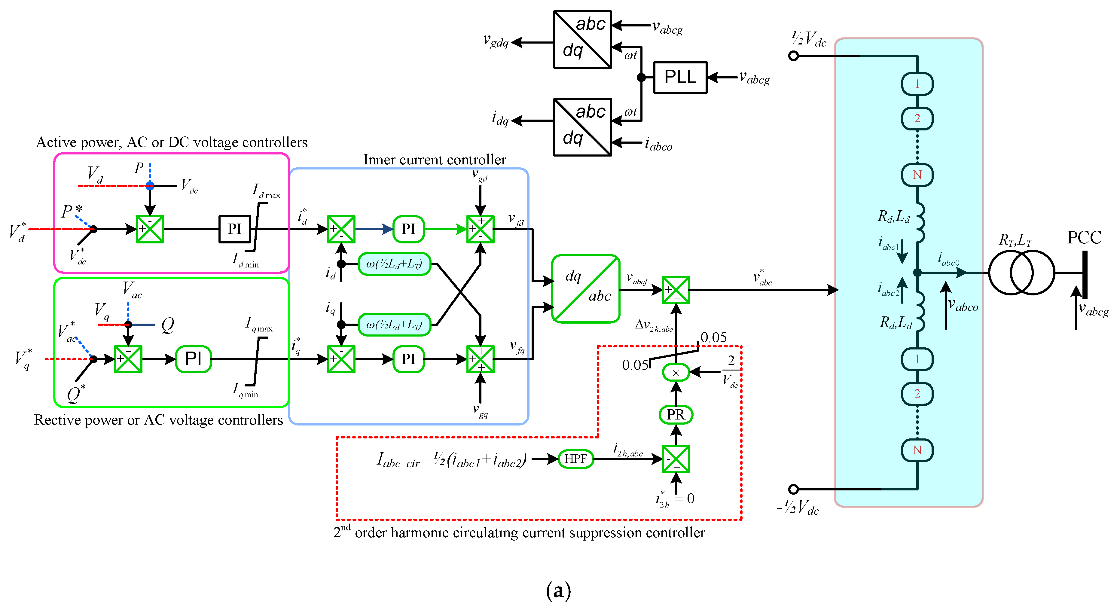
This section assesses two-port and three-port versions of the MPC under investigation. Each sub-converter of the simulated MPC is modelled using the per arm MMC average model in Figure 2b [38], regulated using generic control systems shown in Figure 2a, and simulated in MATLAB-SIMULINK with parameters displayed in Table 1. As shown in Figure 2a, the generic control systems of the sub-converters of the MPCs in Figure 1 consist of the following modes:
- In islanding or grid forming mode, the most outer controllers on d and q axes regulate direct and quadrature axis voltages in an effort to establish stiff AC voltage bus and set the current the current orders for the inner current controllers.
- In grid following, the most outer controllers on d and q axes regulate active power exchange with AC side/or DC voltage and reactive power exchange with AC side/or AC voltage, respectively, and set the current the current orders for the inner current controllers.
- The inner d and q controllers estimate the required AC components of the modulation signals for controlling real and reactive power flows between the sub-converters and AC and DC sides.
- Per phase-leg proportional-resonant controllers tuned at double power frequency are included in each sub-converter as shown in Figure 2 to estimate the required 2nd order harmonic voltage to be injected into the common-mode loop in order to suppress the circulating currents in the MMC arms.
- For simplicity and considering the scope of this work, the DC modulation index of each phase-leg is deliberately regulated at 1. Please refer to [18] for detailed derivation of the control system.
3. Simulations
3.1. Two-Port Converter
3.1.1. Demonstration of Enhanced Control Flexibility When Both AC and DC Sides Are Connected to Active Grids
This subsection uses simulations to demonstrate the enhanced control of the two-port system over rerouting of DC and real powers, between its high- and low-voltage DC terminals and sub-converters 1 and 2 and their respective AC sides. The operating conditions of the simulated two-port system are summarized as follows:
- High and low DC link voltages are Vdc1 = 1300 kV and Vdc2 = 600 kV, respectively, and AC grid voltage is 400 kV line-to-line RMS.
- In time interval, 0 ≤ t < 0.8 s, the upper sub-converter 1 controls the real power it exchanges with the AC grid at −390 MW. The negative sign denotes the power flow is from AC to DC side.
- At t = 0.8 s, the upper sub-converter 1 varies its real power exchange with the AC grid from −390 MW to 650 MW, with the ramp rate of 5.2 MW/ms.
- In interval 0 ≤ t < 1.6 s, the real power exchange of the lower sub-converter 2 with the AC grid is fixed at 390 MW; where the positive sign denotes the power is from the sub-converter to the AC side.
- At t = 1.6 s, the lower sub-converter varies its real power exchange with the AC grid from 390 MW to −650 MW.
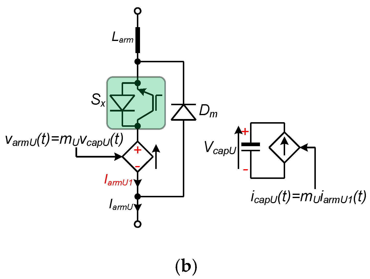
The observations drawn from the simulation waveforms summarized in Figure 3 are:
- The real powers of the upper and lower sub-converters of the two-port system being examined and real power sank or sourced by the AC grid are displayed in Figure 3a. Notice that the two-port system exchanges zero real power with the AC grid, in interval t < 0.8 s, when sub-converters 1 and 2 exchange equal but opposing real powers. In this interval, the two-port system shown in Figure 1b operates as auto DC transformer studied in [37].
- The DC powers of upper and lower sub-converters 1 and 2 of the two-port system, Pdc(upper) = Idc1(Vdc1 − Vdc2) and Pdc(lower) = Idc2Vdc2 and total DC power of the high-voltage DC terminal Pdc1 = Idc1Vdc1 are shown in Figure 3b. Recall that the DC power of the lower sub-converter 2 is equal to the DC power of the low-voltage DC terminal.
- Figure 3c displays the DC components of the arms of the upper and lower sub-converters 1 and 2, Id1 and Id2, and DC currents in the high- and low-voltage DC terminals of the two-port system. Observe that despite a large DC current, which is in the DC link of lower sub-converter 2, no sub-converter is subjected to excessive current stresses, thanks to direct DC current contribution through the arms of upper sub-converter 1 to DC link of the lower sub-converter 2 without passing through its arms.
- Figure 3d,e depicts the three-phase output currents of the upper and lower sub-converters 1 and 2, and these results indicate the independent control of the sub-converters of the two-port system.
- In line with above discussions, the arm currents of the upper and lower sub-converters in Figure 3f,g confirm the point made earlier with regard to no excessive current stresses are observed in the sub-converters despite the large current in the DC link of the low-voltage DC terminal.
3.1.2. Demonstration of Enhanced Power Control in Islanding Mode
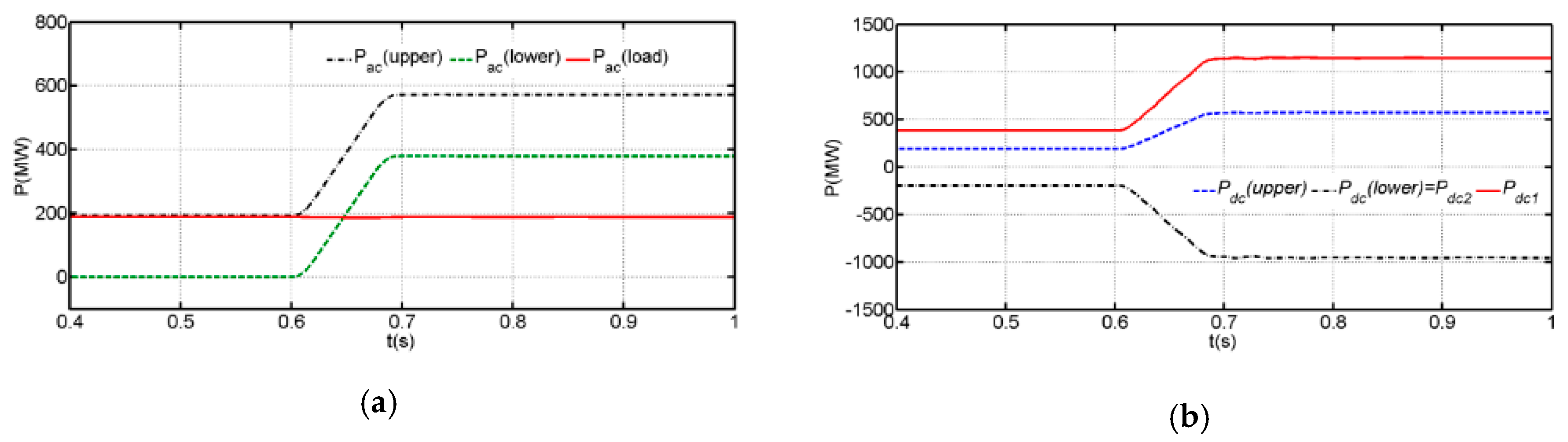
This subsection demonstrates the islanding operation of the two-port system in Figure 1a when its DC side is fed from a symmetrical bipolar DC link voltage of ±600 kV, with its AC side connected to a passive load. The secondary and tertiary windings of the AC transformer are used to connect sub-converters 1 and 2, and the passive load is connected to the transformer primary side. The passive load connected to the AC side consists of 200 MW and 50 MVAr inductive. The upper sub-converter 1 operates in islanding mode and sets constant AC voltage across the passive AC load. In contrast, the lower sub-converter 2 is synchronized to the constant AC voltage established by the upper sub-converter 1 and it is controlled in grid following mode, with primary function of controlling its real power by varying the magnitude and phase angle of its terminal voltage relative to that established by the upper sub-converter 1. In interval, 0 ≤ t < 0.6s, the lower sub-converter 2 of the two-port system controls its real power Pac2 or Pac(lower) at zero, and at t = 0.6 s, Pac2 or Pac(lower) is varied from 0 to 380 MW. The observations drawn from the results in Figure 4 are:
- The real powers of upper and lower sub-converters 1 and 2 and real power of the passive load are shown in Figure 4a. It can be observed that the real power exchange of the upper sub-converter 1 with AC side increases as the lower sub-converters increases its real power import. Note that the positive direction of the real power in the low sub-converter is from AC side toward converter.
- The DC powers of the upper and lower sub-converters, Pdc(upper) and Pdc(lower) of the two-port system and monitored DC powers in the high and low voltage DC terminals Pdc1 and Pdc2 are shown in Figure 4b.
- The DC components of arm currents of the upper and lower sub-converters 1 and 2 superimposed on the DC currents of the high and low voltage DC terminals are shown in Figure 4c. Notice that no currents are observed in the lower sub-converters arms when its real power is controlled at zero, and its DC link current is not zero, i.e., Idc2 = −Idc1 and Id2 = 0, and Pdc(upper) ≈ Pdc(lower) plus AC load real power as shown in Figure 4a–c.
3.2. Three-Port Converter
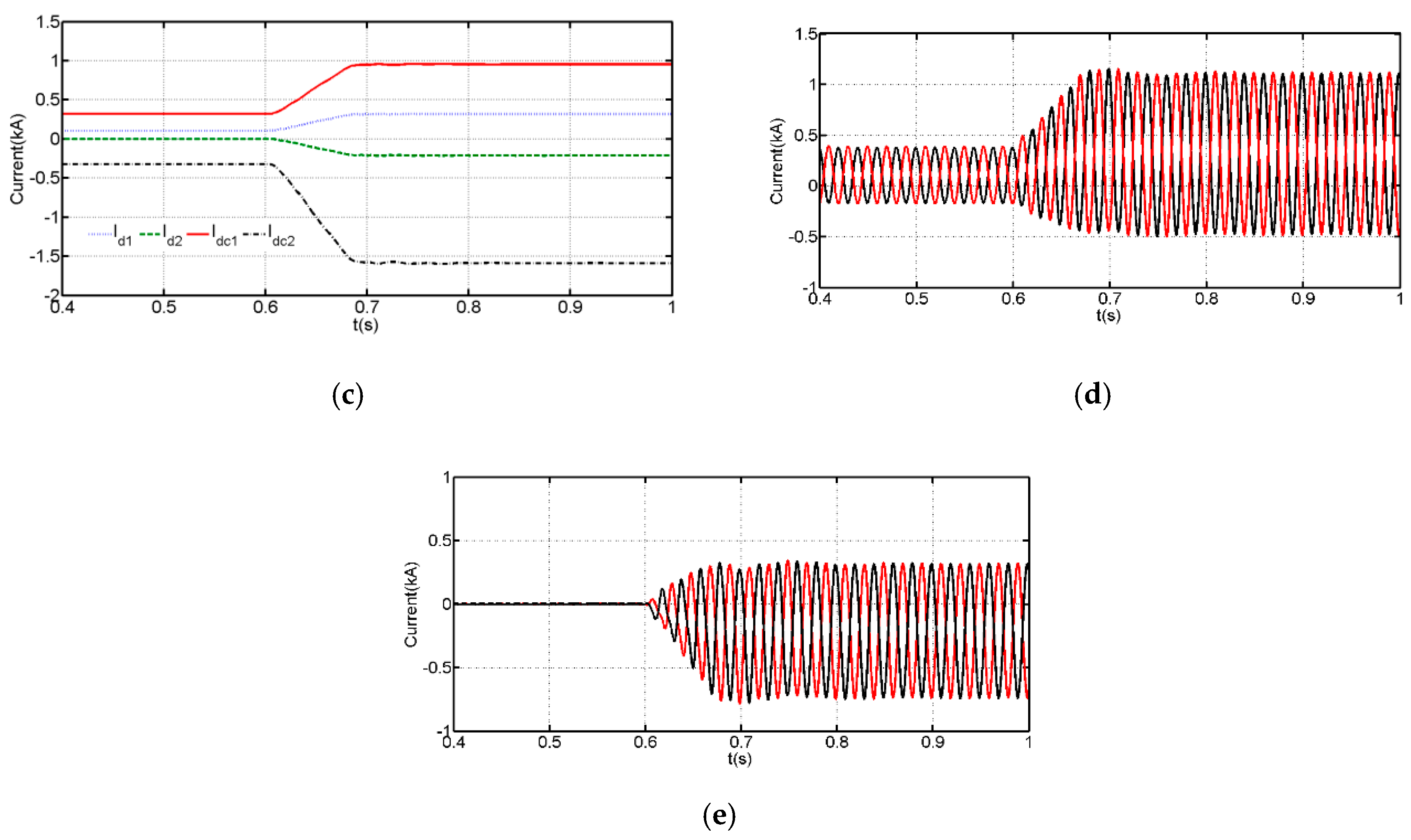
This section uses simulations to assess the improved control flexibility of the tri-port system shown in Figure 1b. Initially, real power set points of sub-converters 1, 2, and 3 are Pac1 = −650 MW, Pac2 = 325 MW, and Pac3 = 325 MW, respectively. At t = 0.8 s, 1.6 s, and 2 s, sub-converters 1, 2, and 3 are instructed to vary their real power set points from −650 MW to +1040 MW, 325 MW to −325 MW, and 325 MW to −455 MW, respectively. The observation drawn from simulation waveforms presented in Figure 5 is as follows:
- The DC powers of sub-converter 1 and at various DC terminals displayed in Figure 5b show that each DC terminal can control its DC power, without affecting the DC power flows in the other terminals to some extent, except when the real power of sub-converter 1 varies. Such relative decoupling is practical important in future DC grids, particularly in which multiple large-scale renewable energy-based power plants are anticipated to be integrated at multiple DC and AC terminals with different voltage levels.
- Figure 5a,b shows that the power distributions in the tri-port converter in Figure 1b adhere to the same theoretical principles that govern the two-port system in Figure 1a, namely, Pac1 = (n − 1)/nPdc1 and Pg = Pac1 + Pac2 + Pac3. Notice that the DC power of the sub-converter 2 varies at t = 0.8 s with real power of sub-converter 1 (Pac1), and this is attributed to DC power exchange from sub-converter 1 to DC link of sub-converter 2, through the DC components of the arm currents of sub-converter 1, with the arm currents of sub-converter 2 remaining unchanged and merely determined by its real power (Pac2) as shown in Figure 5a–f.
- On the other hand, the DC power and current of sub-converter 3 are exclusively defined by its active power (Pac3).
- Observe that arm currents of the sub-converters of the tri-port scheme are completely independent and vary solely and strictly with their respective real powers as shown in Figure 5d–f. Also, the DC current distributions in sub-converters 1 and 2 largely follow the same fundamentals of the two-port converter discussed earlier.
4. Experimental Verifications
4.1. Demonstration of Control Flexibilities
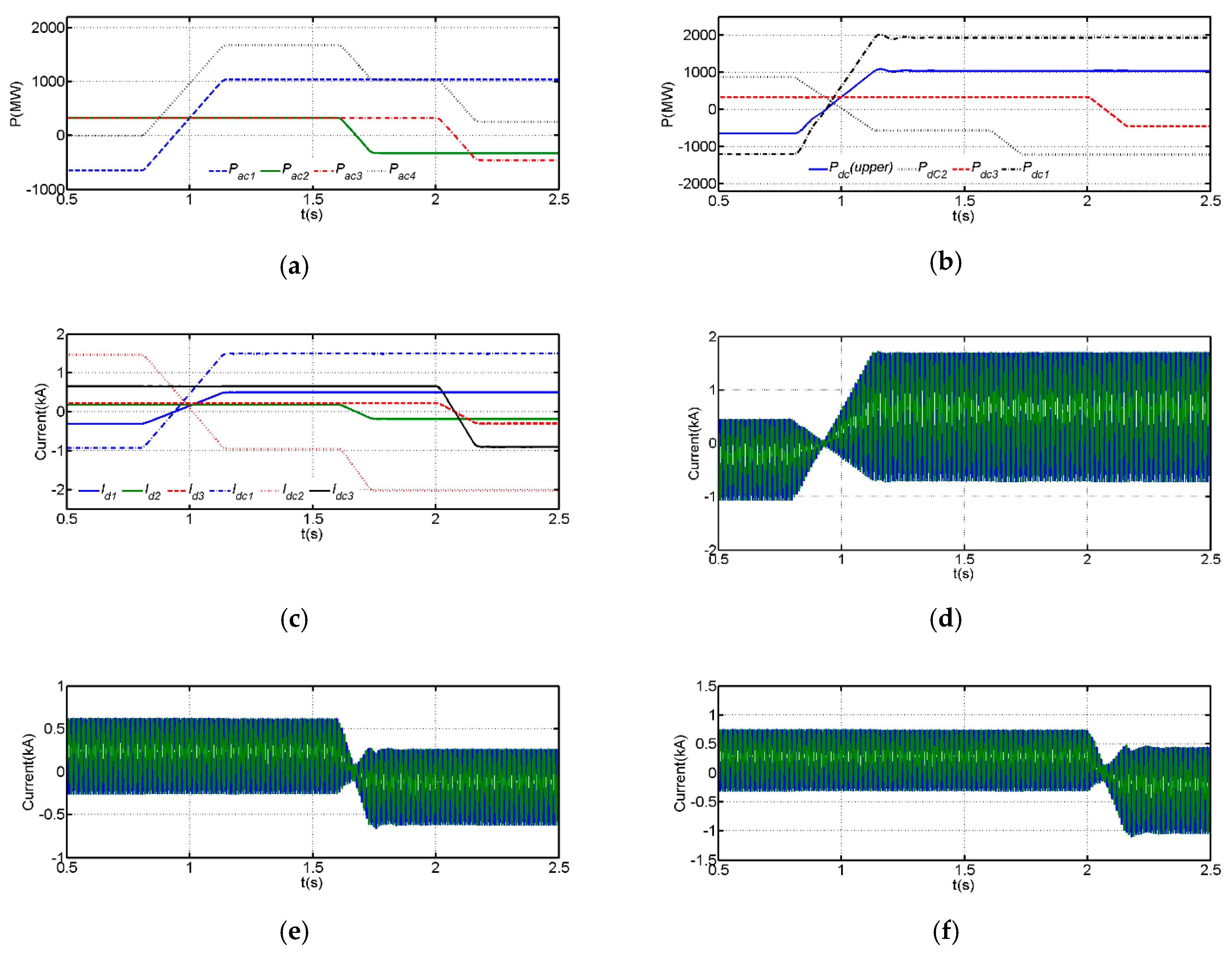
This section cross-validates the theoretical discussions, analysis, and simulation results of the two-port system presented earlier by experimental results from the scale- down prototype of the two-port system in Figure 6a,b. Although all the previous simulations employ MMC in the sub-converters of the two-port system, the experimental test-rig employs the conventional two-level converter (C2LC) instead of the MMC in the sub-converters for simplicity (see Figure 6a,b). The diodes shown in Figure 6a aim to prevent the current flow into single quadrant unidirectional power flow DC supplies, and parallel connected resistors Rp1 and Rp2 aim to ensure that the bidirectional DC power flow is realized using single quadrant DC power supplies. The values of those resistors were selected to satisfy these relationships, Idc1Rp1 < Vdc1 and IdcxRp2 < Vdc2 under all portioning conditions to ensure the series diodes with DC power supplies are always reversed biased. Test-rig parameters are illustrated in detail in Table 2.
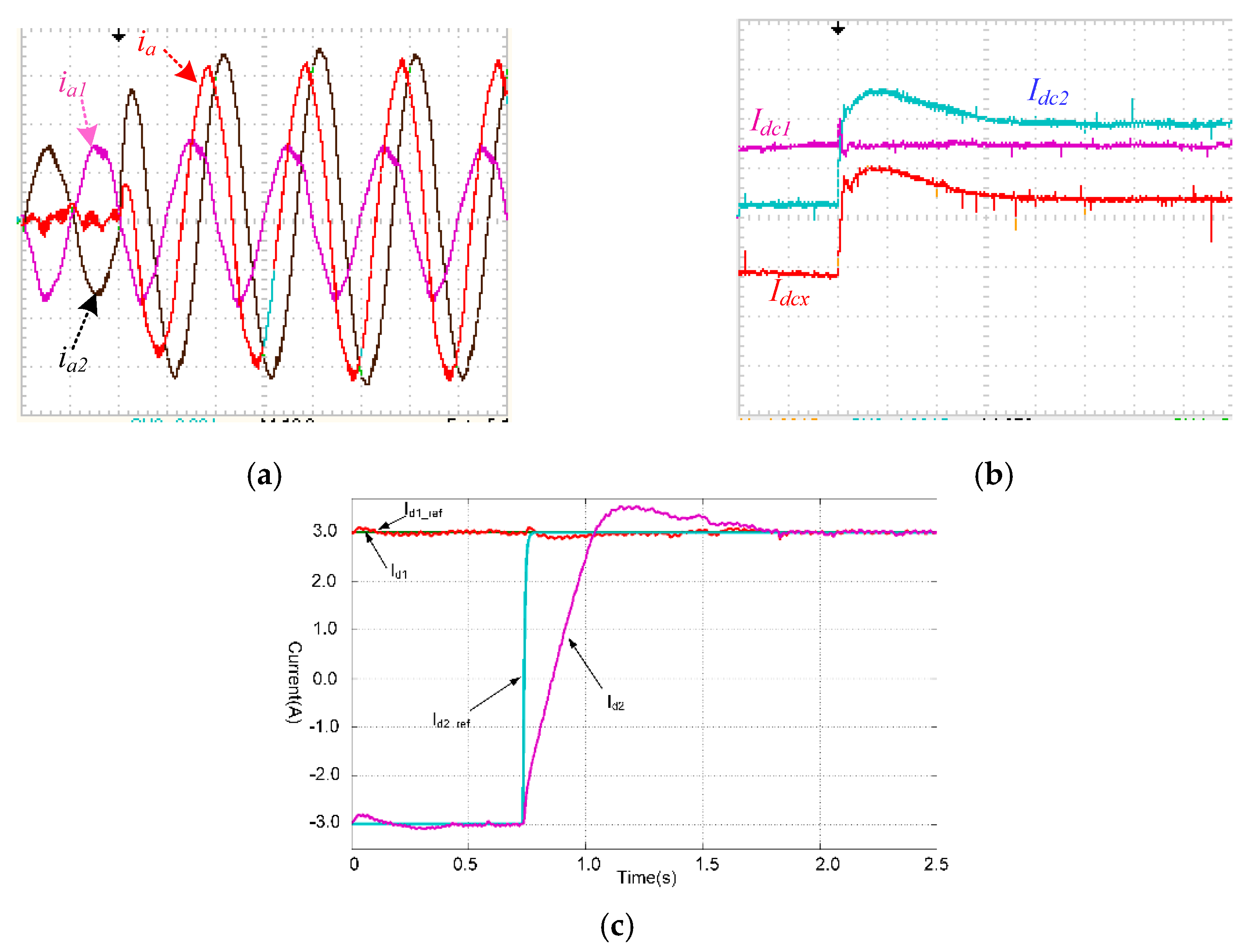
The experimental waveforms obtained from the test-rig of the two-port converter in Figure 6 are shown in Figure 7, when the operating conditions as follows:
- The set-points for the direct and quadrature axis currents of the upper sub-converter 1 are fixed at id1 = 3 A and iq1 = 0.
- The step change is applied to the set-point for the direct current of the lower sub-converter 2, id2, from −3 A to 3 A, while the quadrature axis current is controlled at zero, i.e., iq2 = 0.
Observations drawn from experimental results in Figure 7 are:
- Figure 7a shows samples output phase currents, particularly phase ‘a’ output currents of the upper and lower sub-converter 1 and 2, ia1 and ia2, superimposed to the total phase ‘a’ current injected by the two-port system into the AC grid, ia., in which the black, purple, and red denote the ia1, ia2, and ia, respectively.
- The DC current plots in Figure 7b, which renames the upper and lower voltage DC terminal currents as Idc1 and Idcx, with contribution of the lower sub-converter to dcx is denoted as Idc2.
- Figure 7c shows the direct axis currents of the upper and lower sub-converters 1 and 2, superimposed on their respective current orders. Observe that the output phase currents of the sub-converter follow the commands given to the direct and quadrature axis current components. Noted that a zero current is injected into AC grid current when ia1 = −ia2 or id2 = −id1, which indicate that the two-port system test rig operates as an auto DC transformer as alluded earlier and presented in [37].
4.2. DC Fault
4.2.1. Pole-to-Pole DC Fault at High-Voltage DC Terminal
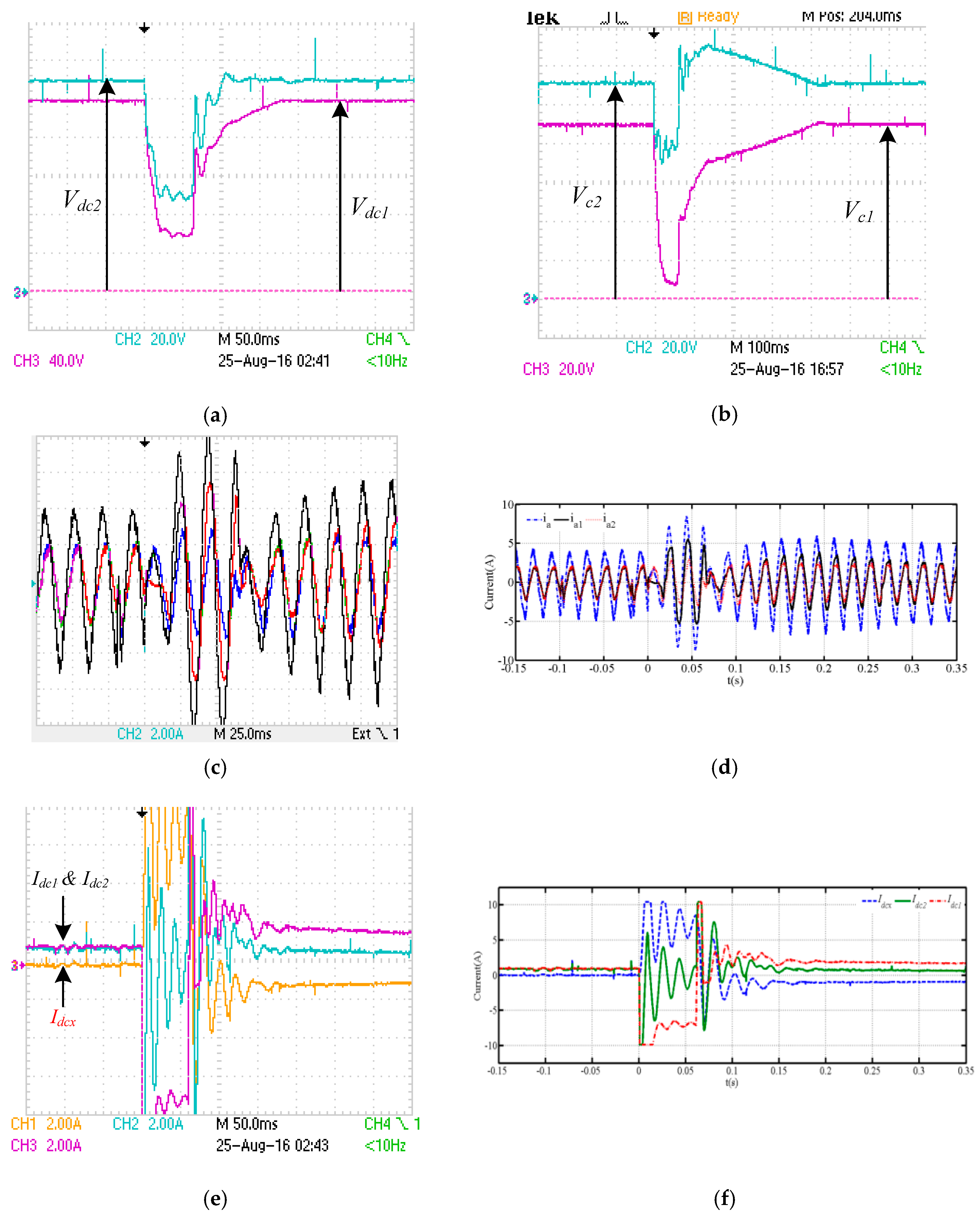
For completeness, this subsection presents experimental assessments of the transient response of the two-port converter is under a temporary DC short circuit fault at the high-voltage DC terminals, i.e., between the positive and negative poles. During the experiment, the system operating conditions are as follows:
- DC voltage of high- and low-voltage terminals are Vdc1 = 200 V and Vdc2 = 110 V, respectively.
- Pre-fault direct and quadrature current orders of sub-converters 1 and 2 are set to and .
- During fault, sub-converters 1 and 2 are blocked, and their direct and quadrature current orders reduced to zero.
The main observations drawn from the selected experimental results that are summarized in Figure 8 are:
- Figure 8a,b presents the voltages of the high and low DC terminals of the experimental two-port system, i.e., Vdc1 and Vdc2, and voltages across the input DC link capacitors of sub-converters 1 and 2. Observe that the DC short circuit across the positive and negative poles, which form the high voltage DC terminal, causes the input voltages of sub-converters 1 and 2 to collapse. This is because the DC fault at this terminal creates a short circuit across the input capacitors of sub-converters 1 and 2. It must be noted the significant collapse of the input DC voltage of sub-converter 2 happened because of the sub-converters employ conventional two-level converter (the same will happen with neutral-point clamped converter or any other topology with reservoir capacitors that tend to discharge during DC fault). When sub-converters employ topologies with hidden capacitors such as the MMC, in which the cell capacitors do not discharge, the input voltage of sub-converter 2 may experience a relatively limited drop due to excessive current.
- Figure 8c,d shows phase ‘a’ output currents of sub-converters 1 and 2 in red and blue, respectively, and the total current being injected into AC grid in black (scope and MATLAB plot from scope comma-separated values (CSV) data, with the latter aiming to show the crests of the AC side currents during fault). Observe that once the input DC voltages of sub-converters 1 and 2 collapse below their respective peaks of the line-to-line AC voltages, high in-feed currents are drawn from the AC side.
- Figure 8e,f displays experimental DC side currents, i.e., Idc1, Idc2, and Idcx, directly from scope and plotted from scope CSV data. These plots show both sub-converters 1 and 2 of the two-port system under investigation are affected by the DC fault at the high-voltage DC terminal, despite that sub-converter 2 has a separate DC source. Also recall that sub-converters 1 and 2 share the same common-mode currents, which cause fast and large rise of Idcx and Idc2. Notice that sub-converter 2 is exposed to relatively low current stresses compared to sub-converter 1, evidently from the DC link currents Idc1 and Idc2. Because of the current limiting inductors employed in the experimental test rig and shown in Figure 6a, observe that the DC current Idcx exhibits a rapid current rise and followed by an extended period of oscillatory and slow decaying to pre-fault level, which started even before the fault is cleared.
- Notice that the Idcx = 0 in pre-fault, and this can be affirmed mathematically as Idcx = Idc1 − Idc2 = ¾Im1cosφ1 − ¾Im2cosφ2 = −¾(Id1 − Id2) = 0; where Id1 = Im1cosφ1 and Id2 = Im2cosφ2, and Iq1 = Im1sinφ1 = 0 and Iq2 = Im2sinφ2 = 0.
In summary, the results in Figure 8 entail that a permanent DC short circuit fault at the high-voltage DC terminal causes the loss of power transfer from sub-converter 1, while it is possible to resume power transfer between the sub-converter 2 and AC grid once the fault is cleared.
4.2.2. Pole-to-Ground DC Fault at Low-Voltage DC Terminal
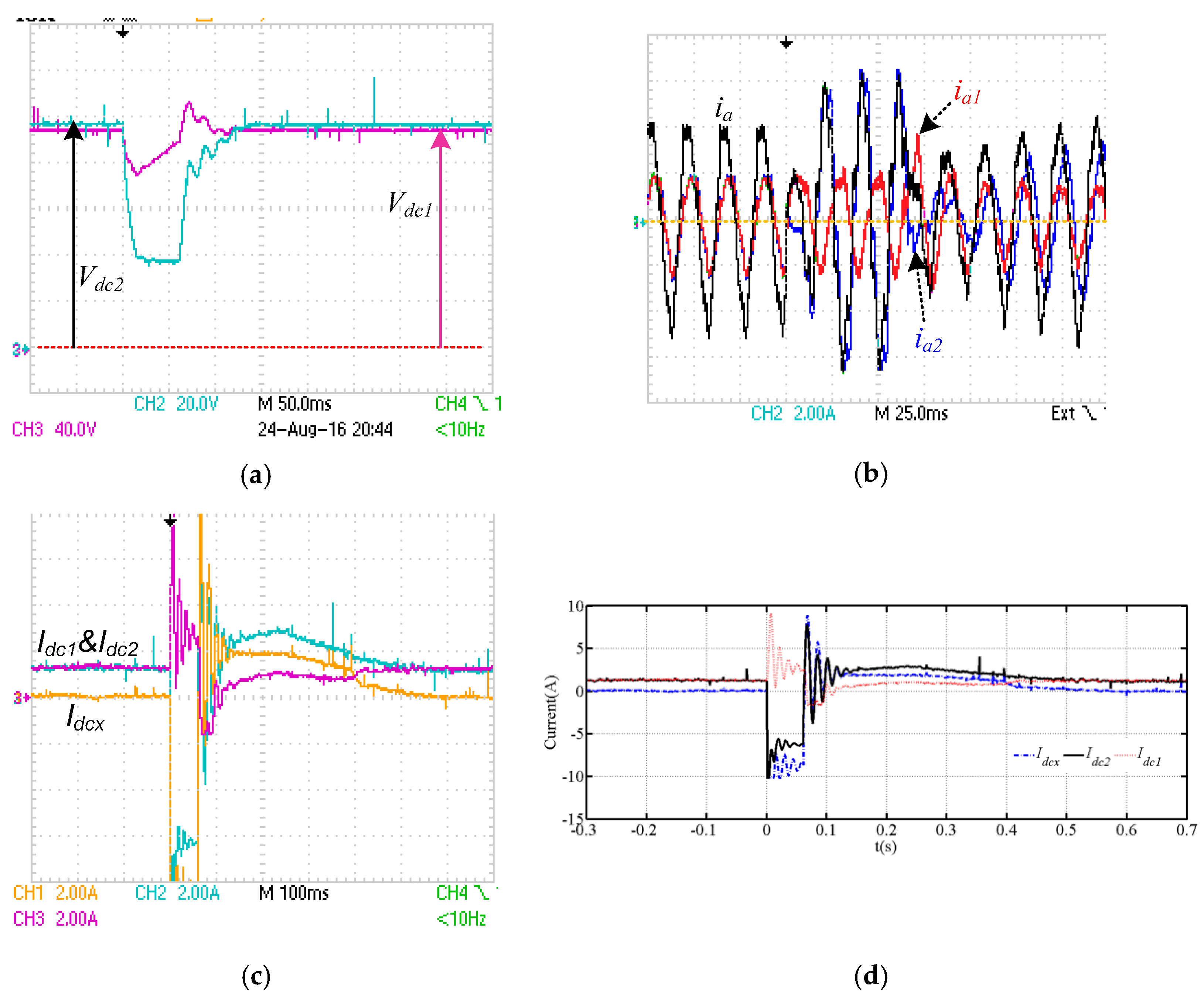
Figure 9 shows experimental waveforms for the two-port converter in Figure 6a when it is subjected to a pole-to-ground DC short circuit fault at the low-voltage DC terminal. The observations drawn from Figure 9 are:
- Figure 9a shows the DC voltages of the high and low DC terminals, Vdc1 and Vdc2. Observe that the DC fault at the low-voltage DC terminal causes a limited drop or fall in the magnitude of the DC voltage of the high-voltage DC terminal; thus, does not significantly its power flow during fault.
- The DC currents, Idc1, Idc2, and Idcx, displayed in Figure 9c,d show brief disturbances in the DC current of sub-converter 1, Idc1, and large disturbances in the DC currents of sub-converter 2, Idc2 and in the Idcx. Although, theoretically, the power flow through sub-converter 1 experiences limited disruption, but practically, the short circuit across sub-converter 2 exposes sub-converter 1 to extremely high voltage equal to Vdc1 instead of Vdc1-Vdc2. Thus, both sub-converters 1 and 2 must be blocked and stopped immediately to avoid devices failures from excessive voltage stresses.
In summary, the results in Figure 9 show the DC short circuit fault at the low-voltage DC terminal presents an over-voltage challenge to sub-converter 1 and requires rapid adjustment of the Vdc1 to a tolerable level. In contrast, DC fault at high-voltage DC terminal presents an over-current problem to sub-converter 2.
5. Conclusions
This paper has investigated the enhanced power control offered by MPC, namely the two-port and tri-port system as practically sound representatives of MPC with multiple DC and AC terminals, which can be adopted for large-scale integration of renewable power generations into future HVDC and UHVDC grids at different DC and AC voltage levels. Theoretical principles that underpin the operation of the MPC under investigation have been described, and substantiated quantitatively, by means of simulations and experimentations, which show that the MPC can control DC and real power flow between multiple DC and AC terminals, and facilitate DC voltage matching and tapping in complex HVDC grids. The main findings and contribution of this works are:
- It presents theoretical analysis and simplified mathematical expressions, which collectively explain the following:
- (a)
- The power flow paths in the MPC systems.
- (b)
- Fundamental relationships that govern the operation of the MMC, including key equations that relate AC and DC powers, AC and DC currents, and DC voltage ratios.
- (c)
- Capacity to manipulate active power set-points of the sub-converters in order to achieve precise control of power flow at AC and DC terminals, including the possibility to reroute power exchange between the AC or DC terminals through particular path or sub-converter as corroborated in Figure 3 and Figure 4. Such a feature could be further exploited to minimize the system operational loss or ensure even heat distribution between the sub-converters.
- It has been shown that sub-converter 1 defines the total DC power and current at the high-voltage DC terminal using its active power set-point. Depending on the exact configuration of the AC side, sub-converter 2 can define the net active power exchange with the AC grid, or the proportion of the DC power of the low voltage DC terminal to be rerouted through the AC side.
- Experimental results in Figure 8 and Figure 9 show that although the fractionally rated power transformer of the MPC and its partial isolation were attractive economically, it is revealed that the MPC is unable to stop a DC fault propagation from faulty terminal to healthy terminal as in the F2F DC-DC converter counterpart; therefore, it will be unable to guarantee adequate level of decoupling between connected networks in order to facilitate DC fault ride-through with no interruption to power flow or continued operation of the healthy network or terminal during fault.
- Despite the incapacity to facilitate continued operation, MPC systems under investigation remain a cost-effective and technically sound solution for integration of renewable energy generations (solar photovoltaic and wind) into medium- and high-voltage AC or DC distribution and transmission systems. Also, it can be used for power tapping from the passing MVDC or HVDC transmission lines to supply power to a small town or village in the way.
Author Contributions
Conceptualization: G.P.A. and F.A.; methodology: G.P.A. and F.A.; software: F.A.; validation: G.P.A. and F.A.; formal analysis: F.A.; investigation: F.A. and G.P.A.; resources: F.A. data curation: F.A.; writing—original draft preparation, F.A.; writing—review and editing, G.P.A.; visualization: F.A.; supervision: G.P.A.; project administration: G.P.A. and F.A.; and funding acquisition: F.A. and G.P.A. All authors have read and agreed to the published version of the manuscript.
Funding
This project was funded by the Deanship of Scientific Research (DSR) at King Abdulaziz University, Jeddah, under grant no. (RG-23-135-39). The authors, therefore, acknowledge with thanks DSR for technical and financial support.
Acknowledgments
The authors would like to thank Ibrahim Abdelsalam of the Arab Academy for Science and Maritime, Cairo branch, for the experimental support and invaluable technical input.
Conflicts of Interest
The authors declare no conflict of interest.
Nomenclature
| DC | Direct Current |
| HVAC | High Voltage Alternating Current |
| MVDC | Medium Voltage Direct Current |
| HVDC | High Voltage Direct Current |
| MV | Medium Voltage |
| HV | High Voltage |
| AC | Alternating Current |
| MPC | Multi-port Converter |
| MTDC | Multi Terminal HVDC |
| MMC | Modular Multilevel Converter |
| DAB | Dual Active Bridge |
| F2F | Front to Front |
| Q2L | Quasi-two Level |
| TAC | Transition Arm Converter |
| FB | Full Bridge |
| SM | Submodule |
| SC | Sub-converter |
| d-axis | direct axis |
| q-axis | quadrature axis |
| C2LC | Conventional Two-level Converter |
| UHVDC | Ultra HVDC |
| Pac and Pdc | Real Power and DC power, respectively |
| Idc and Vdc | DC Current and DC Voltage |
| φ | Phase Shift between the grid voltage and current |
| δ | Voltage Angle at converter terminal with respect to grid voltage |
| Im and Vm | The peaks of the AC current and voltage |
| RT1 and RT2 | Equivalent series resistances referred to secondary and tertiary sides |
| LT1 and LT2 | Equivalent transformer inductances referred to secondary and tertiary sides |
| Rps and Rpt, and Lps and Lpt | The transformer primary windings resistance and inductance referred to secondary and tertiary sides |
| Rs and Rt, and Ls and Lt | Resistances and inductances of the secondary and tertiary windings |
| iabc and vabc | Three phase current and voltage |
| idq and vdq | d-q components of three-phase AC currents and voltages |
References
- Guo, D.; Rahman, M.H.; Adam, G.P.; Xu, L.; Emhemed, A.; Burt, G.; Audichya, Y. Interoperability of Different Voltage Source Converter Topologies in HVDC Grids. In Proceedings of the 15th IET International Conference on AC and DC Power Transmssion Systems, Coventry, UK, 5–7 February 2019. [Google Scholar]
- Wickramasinghe, H.R.; Konstantinou, G.; Li, Z.; Pou, J. Alternate Arm Converters-Based HVDC Model Compatible with the CIGRE B4 DC Grid Test System. IEEE Trans. Power Deliv. 2019, 34, 149–159. [Google Scholar] [CrossRef]
- Wang, S.; Li, C.; Adeuyi, O.D.; Li, G.; Ugalde-Loo, C.E.; Liang, J. Coordination of MMCs With Hybrid DC Circuit Breakers for HVDC Grid Protection. IEEE Trans. Power Deliv. 2019, 34, 11–22. [Google Scholar] [CrossRef] [Green Version]
- Yan, L.; Zhibin, W.; Yongning, C.; Chunxia, W.; Hongzhi, L.; Haiyan, T. Analysis of Coordinated Control Strategy for Large-scale Renewable Energy VSCHVDC Integration. In Proceedings of the 2019 IEEE Innovative Smart Grid Technologies—Asia (ISGT Asia), Chengdu, China, 21–24 May 2019; pp. 234–238. [Google Scholar]
- Wang, X.; Chen, L.; Sun, D.; Zhang, L.; Nian, H. A Modified Self-Synchronized Synchronverter in Unbalanced Power Grids with Balanced Currents and Restrained Power Ripples. Energies 2019, 12, 923. [Google Scholar] [CrossRef] [Green Version]
- Anuradha, C.; Chellammal, N.; Maqsood, M.S.; Vijayalakshmi, S. Design and Analysis of Non-Isolated Three-Port SEPIC Converter for Integrating Renewable Energy Sources. Energies 2019, 12, 221. [Google Scholar] [CrossRef] [Green Version]
- Flourentzou, N.; Agelidis, V.G.; Demetriades, G.D. VSC-Based HVDC Power Transmission Systems: An Overview. IEEE Trans. Power Electron. 2009, 24, 592–602. [Google Scholar] [CrossRef]
- Engel, S.P.; Stieneker, M.; Soltau, N.; Rabiee, S.; Stagge, H.; de Doncker, R.W. Comparison of the Modular Multilevel DC Converter and the Dual-Active Bridge Converter for Power Conversion in HVDC and MVDC Grids. IEEE Trans. Power Electron. 2015, 30, 124–137. [Google Scholar] [CrossRef]
- Mitra, B.; Chowdhury, B.; Manjrekar, M. HVDC transmission for access to off-shore renewable energy: A review of technology and fault detection techniques. IET Renew. Power Gener. 2018, 12, 1563–1571. [Google Scholar] [CrossRef]
- Wang, H.; Wang, Y.; Duan, G.; Hu, W.; Wang, W.; Chen, Z. An Improved Droop Control Method for Multi-Terminal VSC-HVDC Converter Stations. Energies 2017, 10, 843. [Google Scholar] [CrossRef] [Green Version]
- Hwang, S.; Song, S.; Jang, G.; Yoon, M. An Operation Strategy of the Hybrid Multi-Terminal HVDC for Contingency. Energies 2019, 12, 2042. [Google Scholar] [CrossRef] [Green Version]
- Davari, M.; Mohamed, Y.A.I. Dynamics and Robust Control of a Grid-Connected VSC in Multiterminal DC Grids Considering the Instantaneous Power of DC- and AC-Side Filters and DC Grid Uncertainty. IEEE Trans. Power Electron. 2016, 31, 1942–1958. [Google Scholar] [CrossRef]
- Suryadevara, R.; Li, T.; Modepalli, K.; Parsa, L. IPOP-Connected FB-ZCS DC–DC Converter Modules for Renewable Energy Integration with Medium-Voltage DC Grids. IEEE Trans. Ind. Appl. 2019, 55, 5128–5140. [Google Scholar] [CrossRef]
- Páez, J.D.; Frey, D.; Maneiro, J.; Bacha, S.; Dworakowski, P. Overview of DC–DC Converters Dedicated to HVdc Grids. IEEE Trans. Power Deliv. 2019, 34, 119–128. [Google Scholar] [CrossRef]
- Adam, G.P.; Alsokhiry, F.; Al-Turki, Y.; Ajangnay, M.O.; Amogpai, A.Y. DC-DC Converters for Medium and High Voltage Applications. In Proceedings of the IECON 2019—45th Annual Conference of the IEEE Industrial Electronics Society, Lisbon, Portugal, 14–17 October 2019; pp. 3337–3342. [Google Scholar]
- Adam, G.P.; Gowaid, I.A.; Finney, S.J.; Holliday, D.; Williams, B.W. Review of dc–dc converters for multi-terminal HVDC transmission networks. IET Power Electron. 2016, 9, 281–296. [Google Scholar] [CrossRef] [Green Version]
- Adam, G.; Vrana, T.K.; Li, R.; Li, P.; Burt, G.; Finney, S. Review of Technologies for DC Grids -Power Conversion, Flow Control, and Protection. IET Power Electron. 2019, 12, 1851–1867. [Google Scholar] [CrossRef] [Green Version]
- Adam, G.P.; Williams, B.W. Half- and Full-Bridge Modular Multilevel Converter Models for Simulations of Full-Scale HVDC Links and Multiterminal DC Grids. IEEE J. Emerg. Sel. Top. Power Electron. 2014, 2, 1089–1108. [Google Scholar] [CrossRef] [Green Version]
- Gowaid, I.A.; Adam, G.P.; Massoud, A.M.; Ahmed, S.; Williams, B.W. Hybrid and Modular Multilevel Converter Designs for Isolated HVDC–DC Converters. IEEE J. Emerg. Sel. Top. Power Electron. 2018, 6, 188–202. [Google Scholar] [CrossRef]
- Diab, M.S.; Massoud, A.M.; Ahmed, S.; Williams, B.W. A Dual Modular Multilevel Converter with High-Frequency Magnetic Links Between Submodules for MV Open-End Stator Winding Machine Drives. IEEE Trans. Power Electron. 2018, 33, 5142–5159. [Google Scholar] [CrossRef] [Green Version]
- Lin, N.; Dinavahi, V. Dynamic Electro-Magnetic-Thermal Modeling of MMC-Based DC-DC Converter for Real-Time Simulation of MTDC Grid. IEEE Trans. Power Deliv. 2017, 33, 1337–1347. [Google Scholar] [CrossRef]
- Heyman, O. HVDC Light: It Is Time to Connect. December 2012. Available online: www.abb.com/hvdc (accessed on 20 August 2020).
- Shi, L.; Adam, G.P.; Li, R.; Xu, L. Enhanced Control of Offshore Wind Farms Connected to MTDC Network Using Partially Selective DC Fault Protection. IEEE J. Emerg. Sel. Top. Power Electron. 2020. [Google Scholar] [CrossRef]
- Raghavendra, K.V.G.; Zeb, K.; Muthusamy, A.; Krishna, T.N.V.; Kumar, S.V.S.V.P.; Kim, D.-H.; Kim, M.-S.; Cho, H.-G.; Kim, H.-J. A Comprehensive Review of DC–DC Converter Topologies and Modulation Strategies with Recent Advances in Solar Photovoltaic Systems. Electronics 2019, 9, 31. [Google Scholar] [CrossRef] [Green Version]
- Affam, A.; Buswig, Y.M.; Othman, A.-K.B.H.; Bin Julai, N.; Qays, O. A review of multiple input DC-DC converter topologies linked with hybrid electric vehicles and renewable energy systems. Renew. Sustain. Energy Rev. 2021. forthcoming publication. [Google Scholar] [CrossRef]
- Shoja-Majidabad, S.; Hajizadeh, A. Decentralized adaptive neural network control of cascaded DC–DC converters with high voltage conversion ratio. Appl. Soft Comput. 2020, 86, 105878. [Google Scholar] [CrossRef]
- Elserougi, A.; Abdelsalam, I.; Massoud, A.; Ahmed, S. A bidirectional non-isolated hybrid modular DC–DC converter with zero-voltage switching. Electr. Power Syst. Res. 2019, 167, 277–289. [Google Scholar] [CrossRef]
- Gowaid, I.A.; Adam, G.P.; Massoud, A.M.; Ahmed, S.; Holliday, D.; Williams, B.W. Quasi Two-Level Operation of Modular Multilevel Converter for Use in a High-Power DC Transformer With DC Fault Isolation Capability. IEEE Trans. Power Electron. 2015, 30, 108–123. [Google Scholar] [CrossRef] [Green Version]
- Kish, G.J. On the Emerging Class of Non-Isolated Modular Multilevel DC–DC Converters for DC and Hybrid AC–DC Systems. IEEE Trans. Smart Grid 2019, 10, 1762–1771. [Google Scholar] [CrossRef]
- Swarnkar, R.; Verma, H.K.; Patel, R.N. Comparative Analysis of Isolated and Non-Isolated Bi-Directional DC-DC Converters for DC Microgrid. In Proceedings of the 2019 3rd International Conference on Recent Developments in Control., Automation & Power Engineering (RDCAPE), Noida, India, 10–11 October 2019; pp. 557–562. [Google Scholar] [CrossRef]
- Bhaskar, M.S.; Almakhles, D.J.; Padmanaban, S.; Blaabjerg, F.; Subramaniam, U.; Ionel, D.M. Analysis and Investigation of Hybrid DC–DC Non-Isolated and Non-Inverting Nx Interleaved Multilevel Boost Converter (Nx-IMBC) for High Voltage Step-Up Applications: Hardware Implementation. IEEE Access 2020, 8, 87309–87328. [Google Scholar] [CrossRef]
- Reddy, B.M.; Samuel, P. A comparative analysis of non-isolated bi-directional dc-dc converters. In Proceedings of the 2016 IEEE 1st International Conference on Power Electronics, Intelligent Control and Energy Systems (ICPEICES), Delhi, India, 4–6 July 2016; pp. 1–6. [Google Scholar] [CrossRef]
- Elserougi, A.; Abdelsalam, I.; Massoud, A.; Ahmed, S. A Non-Isolated Hybrid-Modular DC-DC Converter for DC Grids: Small-Signal Modeling and Control. IEEE Access 2019, 7, 132459–132471. [Google Scholar] [CrossRef]
- Cheng, T.; Lu, D.D.; Qin, L. Non-Isolated Single-Inductor DC/DC Converter with Fully Reconfigurable Structure for Renewable Energy Applications. IEEE Trans. Circuits Syst. Ii Express Briefs 2018, 65, 351–355. [Google Scholar] [CrossRef]
- Gorji, S.A.; Sahebi, H.G.; Ektesabi, M.; Rad, A.B. Topologies and Control Schemes of Bidirectional DC–DC Power Converters: An Overview. IEEE Access 2019, 7, 117997–118019. [Google Scholar] [CrossRef]
- Guo, D.; Rahman, M.H.; Ased, G.P.; Xu, L.; Emhemed, A.; Burt, G.; Audichya, Y. Detailed quantitative comparison of half-bridge modular multilevel converter modelling methods. In Proceedings of the 14th IET International Conference on AC and DC Power Transmission (ACDC 2018), Chengdu, China, 28–29 June 2018. [Google Scholar]
- Schön, A.; Bakran, M. High power HVDC-DC converters for the interconnection of HVDC lines with different line topologies. In Proceedings of the 2014 International Power Electronics Conference (IPEC-Hiroshima 2014—ECCE ASIA), Hiroshima, Japan, 18–21 May 2014; pp. 3255–3262. [Google Scholar] [CrossRef]
- Zhao, B.; Song, Q.; Li, J.; Xu, X.; Liu, W. Comparative Analysis of Multilevel-High-Frequency-Link and Multilevel-DC-Link DC–DC Transformers Based on MMC and Dual-Active Bridge for MVDC Application. IEEE Trans. Power Electron. 2018, 33, 2035–2049. [Google Scholar] [CrossRef]
- Yang, J.; He, Z.; Pang, H.; Tang, G. The Hybrid-Cascaded DC–DC Converters Suitable for HVdc Applications. IEEE Trans. Power Electron. 2015, 30, 5358–5363. [Google Scholar] [CrossRef]
- Li, P.; Adam, G.P.; Finney, S.J.; Holliday, D. Operation Analysis of Thyristor-Based Front-to-Front Active-Forced-Commutated Bridge DC Transformer in LCC and VSC Hybrid HVDC Networks. IEEE J. Emerg. Sel. Top. Power Electron. 2017, 5, 1657–1669. [Google Scholar] [CrossRef] [Green Version]
- Ray, S.; Gupta, N.; Gupta, R.A. Prototype Development and Experimental Investigation on Cascaded Five-Level Inverter Based Active Filter for Large-Scale Grid-tied Photovoltaic. Int. J. Renew. Energy Res. IJRER 2018, 8, 1800–1811. [Google Scholar]
- Perez, M.A.; Bernet, S.; Rodriguez, J.; Kouro, S.; Lizana, R. Circuit Topologies, Modeling, Control Schemes, and Applications of Modular Multilevel Converters. IEEE Trans. Power Electron. 2015, 30, 4–17. [Google Scholar] [CrossRef]
Figure 1.
Possible configurations of proposed multi-port converters (MPC)s: (a) Two-port converter and (b) three-port converter.
Figure 1.
Possible configurations of proposed multi-port converters (MPC)s: (a) Two-port converter and (b) three-port converter.

Figure 2.
(a) Generic depiction of control systems of arbitrary sub-converter, and (b) per arm average model.
Figure 2.
(a) Generic depiction of control systems of arbitrary sub-converter, and (b) per arm average model.


Figure 3.
Simulation waveforms illustrate the enhanced power control of the MPC with asymmetrical active DC inputs of Vdc1 = 1300 kV and Vdc2 = 600 kV when its AC side is connected to live AC grid: (a) Pac(upper) and Pac(lower), and AC power being exchanged with the AC grid, Pg; (b) Pdc(upper) and Pdc(lower), and DC power at high and low voltage DC terminals, Pdc1 and Pdc2; (c) DC currents in the arms of sub-converters 1 and 2, Id1 and Id2, and in the high- and low-voltage DC terminals, Idc1 and Idc2; (d,e) are three-phase output phase currents of sub-converters 1 and 2; and (f,g) are arm currents of sub-converters 1 and 2.

Figure 4.
Simulation waveforms that Illustrate the enhanced power control functionality of the MPC with symmetrical bipolar DC bus of ±600kV, feeding passive AC island with no generation: (a) Active powers of sub-converters 1 and 2, Pac(upper) and Pac(lower), and d active power of the AC load; (b) DC powers of sub-converters 1 and 2, Pdc(upper) and Pdc(lower), and in the high- and low-voltage DC terminals; (c) DC currents in the arms of sub-converters 1 and 2, Id1 and Id2, and in the high- and low-DC terminals; and (d,e) are phase A upper and lower arm currents of sub-converters 1 and 2.


Figure 5.
Simulation waveforms illustrate the improved power control of the three-port converter when all its DC terminals are connected to active DC networks, with Vdc1 = 1300 kV, Vdc2 = 600 kV, and Vdc3 = 500 kV, and its AC side is connected AC grid: (a) Active powers of sub-converters 1, 2, and 3, and active power exchange with the AC grid; (b) DC powers of sub-converters 1, 2, and 3; (c) DC currents in the arms of sub-converters 1, 2, and 3 and in the high-voltage and low-voltage DC links; and (d–f) are arm currents of sub-converters 1, 2, and 3.

Figure 6.
(a,b) are details of the prototype (diagram and photo) when sub-converters 1 and 2 are realized by the conventional two-level converters where 1 and 2 signify sub-converters 1 and 2; 3 and 4 signify AC filters of sub-converters 1 and 2; 5 is a microcontroller that is used to program modulation and control systems of the two-port systems; 6 and 7 are voltage and current sensors; and 8 depicts the gate-drives and circuity that generates complementary gate signals.

Figure 7.
Experimental demonstration of the control flexibility of two-port system when the quadrature currents of upper and lower sub-converters 1 and 2 are regulated at zero, iq1 = iq2 = 0, direct axis currents of sub-converter 1 is regulated at id1 = 3A, and step change is applied to the direct axis currents of sub-converter 2, id2, from −3A to −3A: (a) Snapshot of the (ia1, ia2 and ia) zoomed around the time of application of step change to id2; (b) DC link currents of sub-converters 1 and 2; and (c) direct axis currents of the upper and lower sub-converters 1 and 2. The scales are maintained at (10 ms/div and 2A/div).

Figure 8.
Experimental waveforms when a momentary DC short circuit fault is applied to the high-voltage DC terminal: (a) DC voltages of the high and low DC terminals; (b) DC voltages across the reservoir capacitors of sub-converters 1 and 2; (c,d) are phase ‘a’ currents, ia, ia1, and ia2, measured at the primary, secondary, and tertiary windings of the interfacing transformer, scope, and plotted from scope CSV data; (d) DC currents, Idc1, Idc2, and Idcx; and (e,f) are DC link currents from scope and plotted from scope CSV data.

Figure 9.
Experimental waveforms of the two-port converter when subjected a temporary pole-to-ground DC fault at low-voltage DC terminal: (a) DC voltages of the high and low DC terminals; (b) Phase ‘a’ currents ia, ia1, and ia2 measured at the primary, secondary, and tertiary windings of the interfacing transformer that connects sub-converters 1 and 2 to the AC grid side; (c,d) DC currents Idc1, Idc2, and Idcx directly captured from scope screen and plotted from CSV scope data.


Table 1.
Simulation parameters.
| Parameter | Value |
|---|---|
| Arm resistors | Rd1 = Rd2 = 0.5 Ω, Rd3 = 0.4 Ω |
| Arm inductors | Ld1 = Ld2 = 45 mH and Ld3 = 30 mH |
| Cell capacitors | Cm1 = Cm2 = 10 mF and Cm3 = 8 mF |
| Interfacing AC transformer windings parameters | Rp = Rs = Rt = 0.002 pu, Lp = Ls = Lt = 0.05 pu |
| Interfacing AC transformer ratings | 1300 MVA and 400 kV/300 kV/300 kV |
| AC grid ratings | 400kV AC grid with 15,000 MVA three-phase short circuit fault level and X/R = 15 |
Table 2.
Test rig parameters.
| Parameters | Value |
|---|---|
| Grid voltage | 45 Vrms at 50 Hz |
| DC voltage of the high-voltage DC terminal (Vdc1) | 190 V |
| DC voltage of the low-voltage DC terminal (Vdc2) | 100 V |
| AC side filtering inductance (LF) | 2.6 mH |
| AC filtering capacitance (CF) | 30 μF |
| Transformer voltage ratio | 400 V/415 V/415 V |
| Carrier frequency | 2.4 kHz |
| DC link capacitances of sub-converters 1 and 2 | 2.2 mF |
© 2020 by the authors. Licensee MDPI, Basel, Switzerland. This article is an open access article distributed under the terms and conditions of the Creative Commons Attribution (CC BY) license (http://creativecommons.org/licenses/by/4.0/).
Share and Cite
MDPI and ACS Style
Alsokhiry, F.; Adam, G.P. Multi-Port DC-DC and DC-AC Converters for Large-Scale Integration of Renewable Power Generation. Sustainability 2020, 12, 8440. https://0-doi-org.brum.beds.ac.uk/10.3390/su12208440
AMA Style
Alsokhiry F, Adam GP. Multi-Port DC-DC and DC-AC Converters for Large-Scale Integration of Renewable Power Generation. Sustainability. 2020; 12(20):8440. https://0-doi-org.brum.beds.ac.uk/10.3390/su12208440
Chicago/Turabian StyleAlsokhiry, Fahad, and Grain Philip Adam. 2020. "Multi-Port DC-DC and DC-AC Converters for Large-Scale Integration of Renewable Power Generation" Sustainability 12, no. 20: 8440. https://0-doi-org.brum.beds.ac.uk/10.3390/su12208440
Note that from the first issue of 2016, this journal uses article numbers instead of page numbers. See further details here.