Hypothesis

Numerical Study of Fire and Energy Performance of Innovative Light-Weight 3D Printed Concrete Wall Configurations in Modular Building System

by
Thadshajini Suntharalingam
1,
Perampalam Gatheeshgar
1,
Irindu Upasiri
2,
Keerthan Poologanathan
1,*,
Brabha Nagaratnam
1,
Heshachanaa Rajanayagam
1 and
Satheeskumar Navaratnam
3
1
Department of Mechanical and Construction Engineering, Faculty of Engineering and Environment, Northumbria University, Newcastle upon Tyne NE1 8ST, UK
2
Department of Civil Engineering, Faculty of Engineering, University of Sri Jayewardenepura, Ratmalana 10390, Sri Lanka
3
Depertment of Civil and Infrastructure Engineering, School of Engineering, RMIT University, Melbourne, VIC 3000, Australia
*
Author to whom correspondence should be addressed.
Sustainability 2021, 13(4), 2314; https://0-doi-org.brum.beds.ac.uk/10.3390/su13042314
Submission received: 29 January 2021 / Revised: 11 February 2021 / Accepted: 13 February 2021 / Published: 20 February 2021
(This article belongs to the Special Issue Sustainable Innovative Solutions for Material Efficient Buildings)

Abstract

:
3D Printed Concrete (3DPC) technology is currently evolving with high demand amongst researches and the integration of modular building system (MBS) with this technology would provide a sustainable solution to modern construction challenges. The use of lightweight concrete in such innovative construction methods offers lightweight structures with better heat and sound insulation compared to normal weight concrete. It is worth noting that fire and energy performance has become central to building design. However, there are limited research studies on the combined thermal energy and fire performance of 3DPC walls. Therefore, this study investigates fire performance of 20 numbers of varying 3DPC wall configurations using validated finite element models under standard fire conditions. The fire performance analysis demonstrated that 3DPC non-load bearing cavity walls have substantial resistance under standard fire load and its performance can be further improved with Rockwool insulation. There is significant improvement in terms of fire performance when the thickness of the walls increases in a parallel row manner. Previous thermal energy investigation also showed a lower U-value for increased thickness of similar 3DPC walls. This research concludes with a proposal of using 3DPC wall with Rockwool insulation for amplified combined thermal energy and fire performance to be used in MBS.

1. Introduction

3D printing technology is one of the rapidly developing areas and it has increasingly attracted academic researches and industries, as it helps with complex designs which are challenging to create with conventional manufacturing methods [1,2]. As time progressed, the potential of 3D printing has been clearly recognised in wide range of applications such as food, medical supplies, aeronautics and even agriculture [2,3,4] At present, the building codnstruction industry has also adopted this technique with the aim of turning the complex building design into reality [5]. 3D Printed Concrete (3DPC) techniques that are based on layered extrusion seem to be the most promising approach with respect to both its economic feasibility and to its prospective use in construction practices [2,6]. Adopting 3D printing can be a great asset, regardless of the type of manufacturing sector, as it offers innovative solutions, better time management, faster production, manpower and cost reduction, waste reduction, multi-material printing, and smaller environmental footprint [6,7,8,9]. The technology of producing houses and other structures using this method has dramatically improved since 2010 [2,10]. However, in terms of structural integrity and durability of the structure, there is more to discover.
Concrete is the most popular construction material in the world due to its numerous advantages [6,11] and it has also shown excellent fire performance [12,13,14,15]. Even though concrete has many advantages, one of the vital drawbacks in concrete is its high self-weight [16]. Therefore, many research studies have been conducted to develop lightweight concrete. Lightweight concrete can be categorised as lightweight aggregate concrete and lightweight cellular concrete [17]. The lightweight cellular concrete can be further categorised into two forms that are Autoclaved Aerated Concrete (AAC) and Foamed Concrete (FC) [18]. Foamed concrete is produced by mixing foaming agent to the concrete mix, which makes the concrete cellular with compressed air [19,20]. The potential use of foamed concrete has increased in the industry due to its low self-weight, thermal insulation, acoustic absorption, earthquake resistant, long life span due to fire resistance, weatherproof, workability, and material savings [20,21,22,23,24,25,26]. Hence, this study includes foamed concrete as the material used to develop the numerical models of 3DPC walls.
Structural fire damage or fire losses can be identified as a common accidental disaster throughout the world which causes thousands of deaths, injuries, and millions of property damage each year [12,16,26]. Structural design code of practices has identified the fire situation as an accidental loading condition to the structure. Therefore, it is essential to design the structures to withstand a fire scenario for a prescribed period [26,27,28] Fire can be identified as a time-dependent temperature variation. ISO 834 temperature time relationships [29] given in Equation (1), where T is the fire temperature, T 0 is the ambient temperature and t is time in minutes.
T = 345 log 10 ( 8 t + 1 ) + T 0
At present, Weng et al. [30] and Cicione et al. [31] performed the preliminary experimental studies to analyse the behaviour of 3DPC at elevated temperatures. Following the results presented by Cicione et al. [31], preliminary numerical studies were conducted by Suntharalingam et al. [32,33] focusing on investigating the fire performance of 3DPC composite wall panels under standard fire condition and different fire scenarios. (i.e., hydrocarbon fire, rapid, and prolong).
Another core aims of construction industry is to reduce significant amount of energy consumption, while achieving the desired structural and thermal performance [34,35,
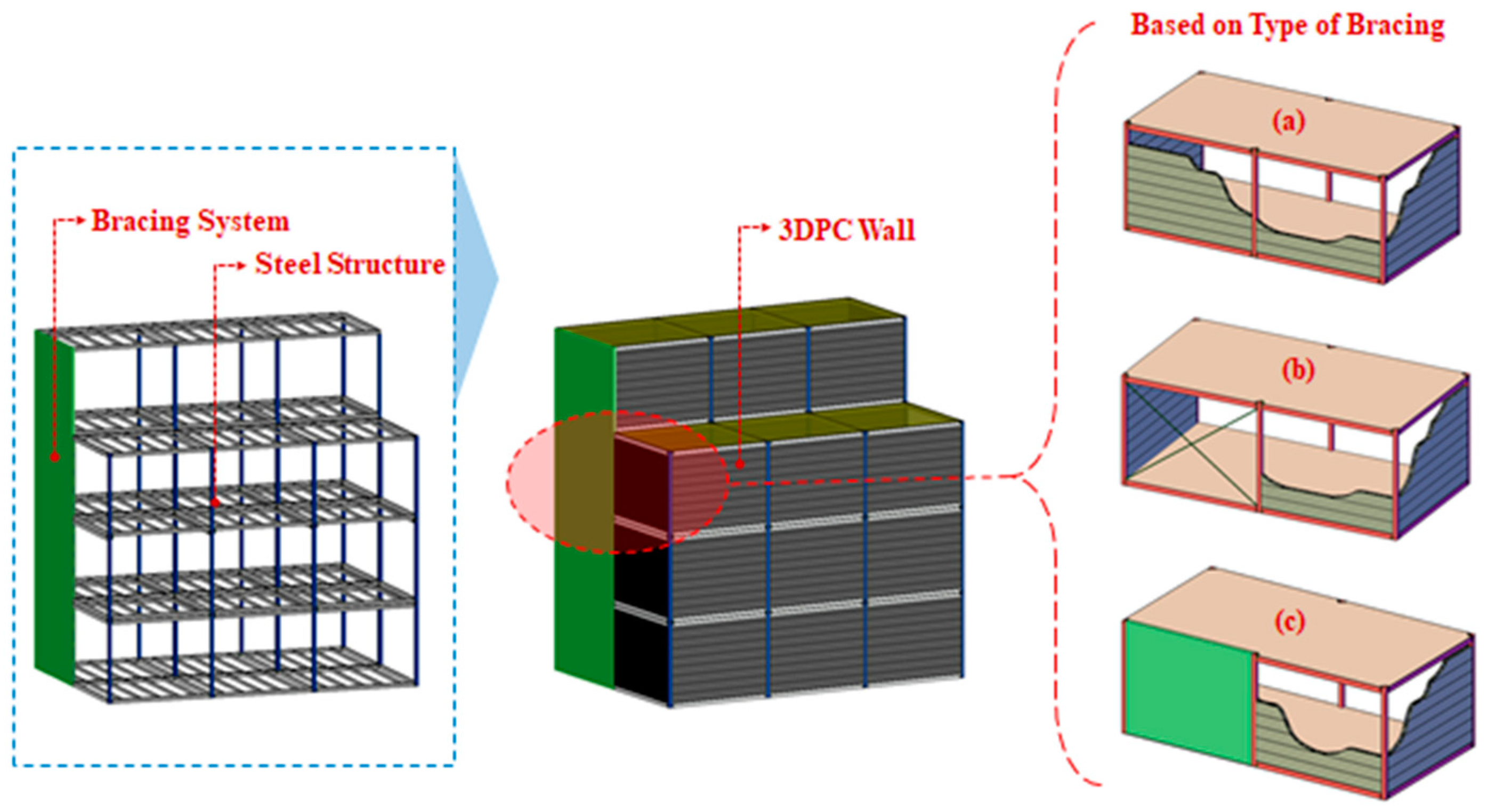
36]. 3DPC technique can be addressed as an environmentally friendly solution which offers sustainable construction. In addition, the adoption of modular building system (MBS) in high rise structure is in demand nowadays and the 3DPC technique will definitely play a major role in the future of MBS. Any complicated architecture, with complicated shapes could be made possible in modular construction by incorporating the 3DPC elements. Moreover, many researchers have discussed the need for SHS corner post section to be covered to protect against fire. Hence, the 3DPC walls with better fire performance could be incorporated with MBS to improve the fire behaviour of the whole structure.
Alkhalidi and Hatuqay [34], investigated and developed energy efficient and low-cost residential 3DPC elements that can be accomplished through a green and sustainable method. He et al. [37], developed 3D concrete printed modular building with integrated vertical greenery system, called 3D printed Vertical Green Wall (3D-VtGW). The energy saving potential of a small commercial building was established using 3D printed modular living wall system. Moreover, Mohammad et al. [38] developed a high strength, lightweight concrete mixture suitable for 3DPC which showed improved thermal insulation, while reducing the energy consumption within the life cycle of the concrete structure.
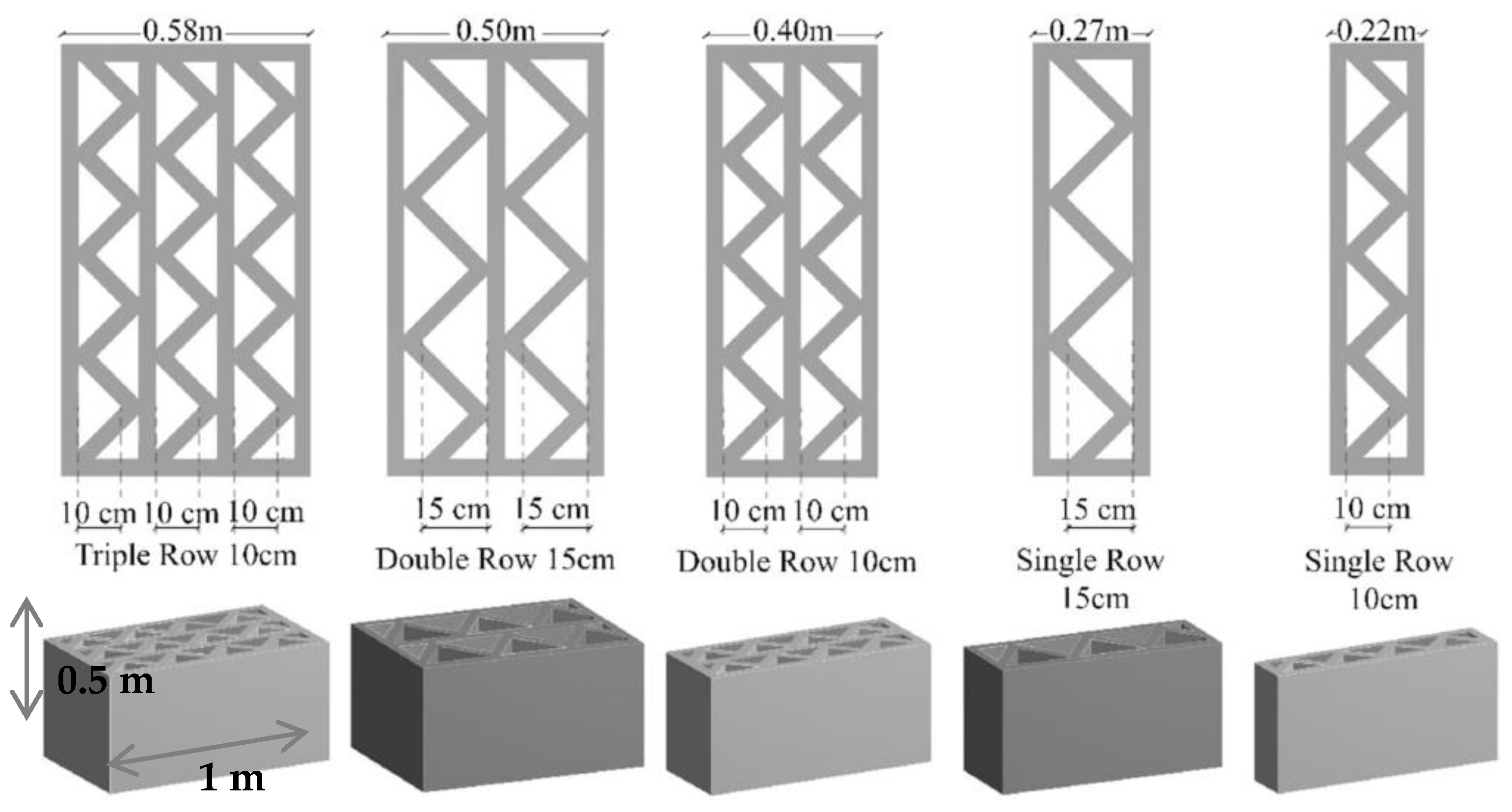
However, researchers are focusing more on the structural performance of 3DPC structures. Moreover, many design guidelines and performance under elevated temperature are available for normal weight concrete, whereas very few studies have evaluated the fire performance and thermal energy of 3DPC structures. Therefore, there is an inevitable absence of literatures to investigate the performance of 3DPC structures at elevated temperatures experimentally and numerically. Hence, this study is more concerned about the fire performance and thermal comfort of the 3DPC buildings in a MBS. This study numerically investigates the fire performance of the innovative 3DPC wall configurations proposed by Alkhalidi and Hatuqay [34]. To conclude, this article describes the fire performance of 3DPC wall panels subjected to standard fire, via a detailed parametric study of 20 numerical models covering five different 3DPC wall configurations with cavity and Rockwool infilled walls with two varying densities. The consequences of the study will potentially help to the growth in practice of safe and sustainable 3D printing technology in the building and construction industry.

2. Study on Energy Efficient 3D Printed Buildings

A study by Alkhalidi and Hatuqay [34] was aimed to develop sustainable low cost residential buildings with efficient energy performance with improved thermal comfort. It involves investigation of the energy performance of 3D printed houses globally in different climatic zones. The thermal comfort of a building is evaluated by the thermal transmittance value (U-value) of the element which will be decided according to the climate condition of the location. Introducing air gaps or insulation layers between the building elements helps to reach the certain U-value according to its climatic conditions. 3D concrete printing offers this design flexibility to print structures with air cavities while satisfying both thermal and structural requirements [34].

2.1. Research Methodology

The study approach was designed as to accomplish an energy efficient 3DPC building by reducing the U-values of the painted walls in compliance with climatic zone regulations. Five different 3DPC wall configurations with three different materials with excellent thermal properties were used in this study. The densities of Mix 1, Mix 2, and Mix 3 are 1254.24, 986, and 1522 kg/m3, respectively. The proposed configurations were selected based on the actual executed 3D printed walls in the current industry. They were printed with different cavity configurations and geometries similar to hollow bricks with 40 mm square nozzle. The wall configurations with 1 m length and 0.5 m height with different cavities of 10 cm and 15 cm in width were analysed. Additionally, the low cost, easily available dry sand and Expanded Polylactic acid (E-PLA) were used to fill the cavities to achieve a lesser U-value. All three heat transfer processes such as conduction, convection, and radiation were considered in the analysis. The different 3DPC wall configurations are shown in Figure 1.

2.2. Model Development

Three-dimensional heat transfer simulation considering steady-state and laminar airflow was performed to calculate the U-value of the 3DPC walls. The wall configurations were designed using ANSYS software and the models were validated against the thermal analysis on numerous cavity arrangements of hollow concrete bricks performed by Henrique dos Santos et al. [39]. Neumann–Dirichlet type boundary conditions were used as two parallel surfaces were considered adiabatic at different temperatures, creating a perpendicular heat flux to those surfaces possible. The Discrete Ordinate Radiation Model (DORM) was applied to determine the radiative heat transfer inside the air cavities. The mesh was created with 3 mm edge length cubic elements.
Heat flux through the designed walls is calculated using ANSYS software, and then the U-value is evaluated using Equation (2).
U = q Δ T
where q is the surface average weighted heat flux, and ΔT is the temperature difference between the indoor and outdoor temperatures defined by the user. The design temperature difference (ΔT) of 20 K, 30 K, and 40 K were determined by maintain the constant ambient temperature at 24 °C. According to the standards and regulations, two U-values of 0.2 and 0.5 W/m2.K were targeted in this study. These U-values were simulated at the abovementioned temperature differences [34].

2.3. Outcomes of the Corresponding Study

The wall configurations with multiple rows showed the minimum thermal transmittance value of 0.15 W/m2.K which revealed the optimal balance between cavities and 3D printed material with the desired U-value and structural performance. Moreover, results indicate that the addition of parallel cavity rows significantly decreases the U-value compared to increasing the cavity size. Table 1 shows the reduction percentage of the U-values for each configuration, compared to the single row 10 cm cavity wall configuration for Mix 3. The minimum U-values were achieved with the triple row 10 cm cavity height for all three mixes and the U-values decreased with increasing density. However, the temperature difference effect on the U-value becomes insignificant with increasing wall thickness that is beyond the double row 15 cm cavity configuration. Hence, the triple row 10 cm cavity configuration was not considered, while indicating a suitable configuration for different climate zones.
Figure 2 illustrates the U-value variation for 3DPC walls with air cavity, sand-filled, and E-PLA filled cavities printed using Mix 3 at ΔT 40 K. The variation remains similar to all three materials Mix 1, Mix 2, and Mix 3 used in this study. It is obvious that cavity filling has reduced the U-values and the E-PLA filling achieved the minimum U-value.
In conclusion, this study has recommended the best material mix, wall configuration and printing method to suit the different climatic zones of the world categorised according to the Koppen–Geiger climate classification. The selections were made by considering the minimum number of cavity rows with less material usage. This paper presents the targeted U-values for each zone referring the national regulations of the world’s climatic zones. Thus, to achieve the targeted U-value of 0.18 W/m2.K for walls in the London region, UK, binder jet, E-PLA filled double row 15 cm configuration with Mix 3 was proposed, as it achieved the U-value of 0.15 W/m2.K (Figure 2).

3. Development of Finite Element Model

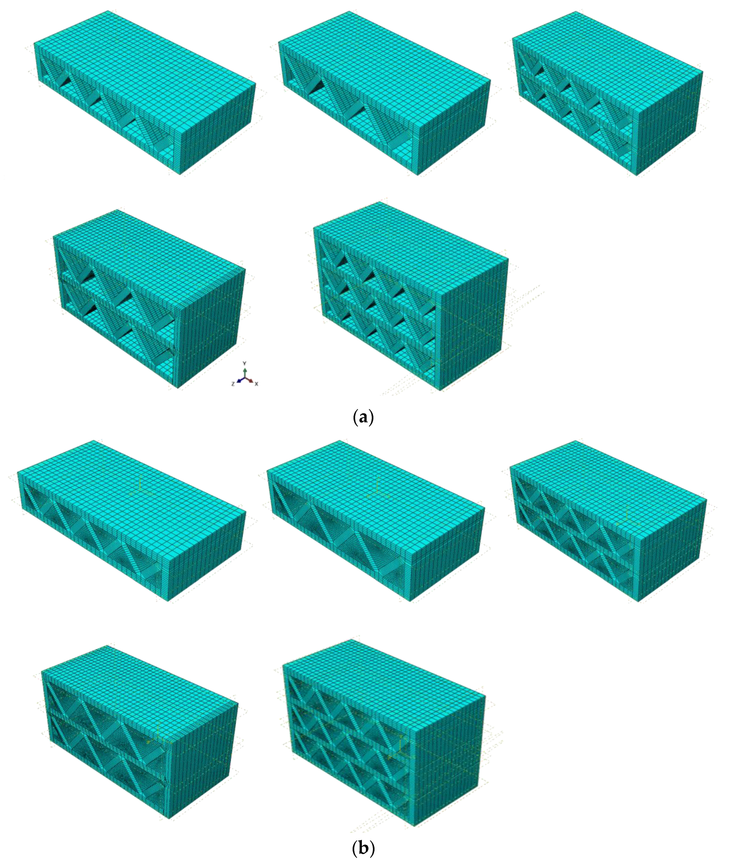
This section explains the development of the three-dimensional Finite Element (FE) model for analysing the heat transfer thermal behaviour of the 3DPC wall panels with different cross-sectional arrangements. The ABAQUS [40] software is used in this study which allows uncoupled and coupled thermal analysis to examine the thermal behaviour of structures. The overall fire performance of a structure has to be analysed under three primary criteria such as insulation, integrity, and structural load bearing capacity [16,
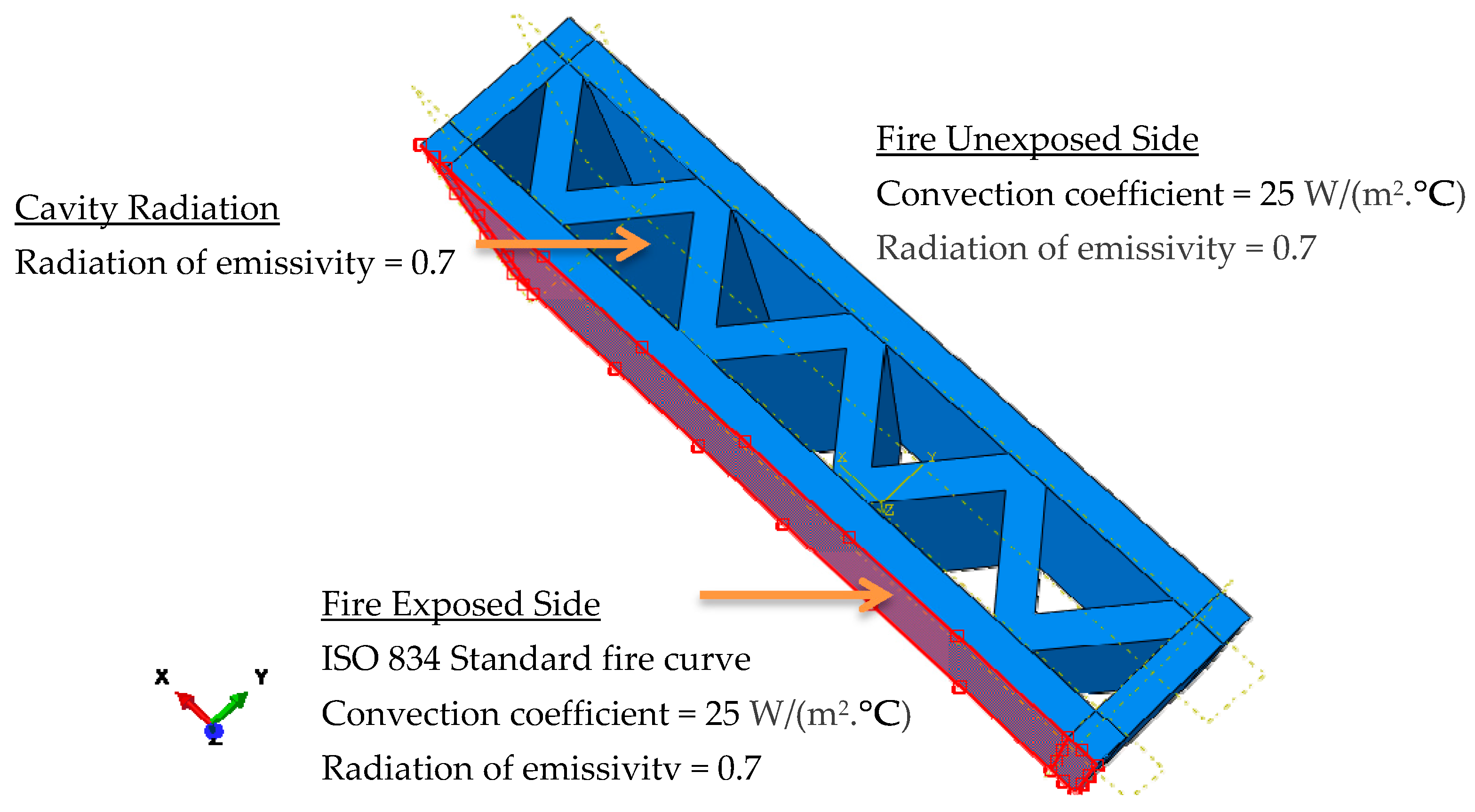
26]. This is known as coupled analysis which investigates the combined mechanical-thermal behaviour. As this study is focused only on non-load bearing walls, uncoupled heat transfer analysis has been performed. The selected wall panels were exposed to normal fire under ISO 834 standard fire scenario [41] and the insulation failure analysis was conducted by measuring the unexpected surface temperature variation. Rockwool material is used as the fire insulation material here in this study.
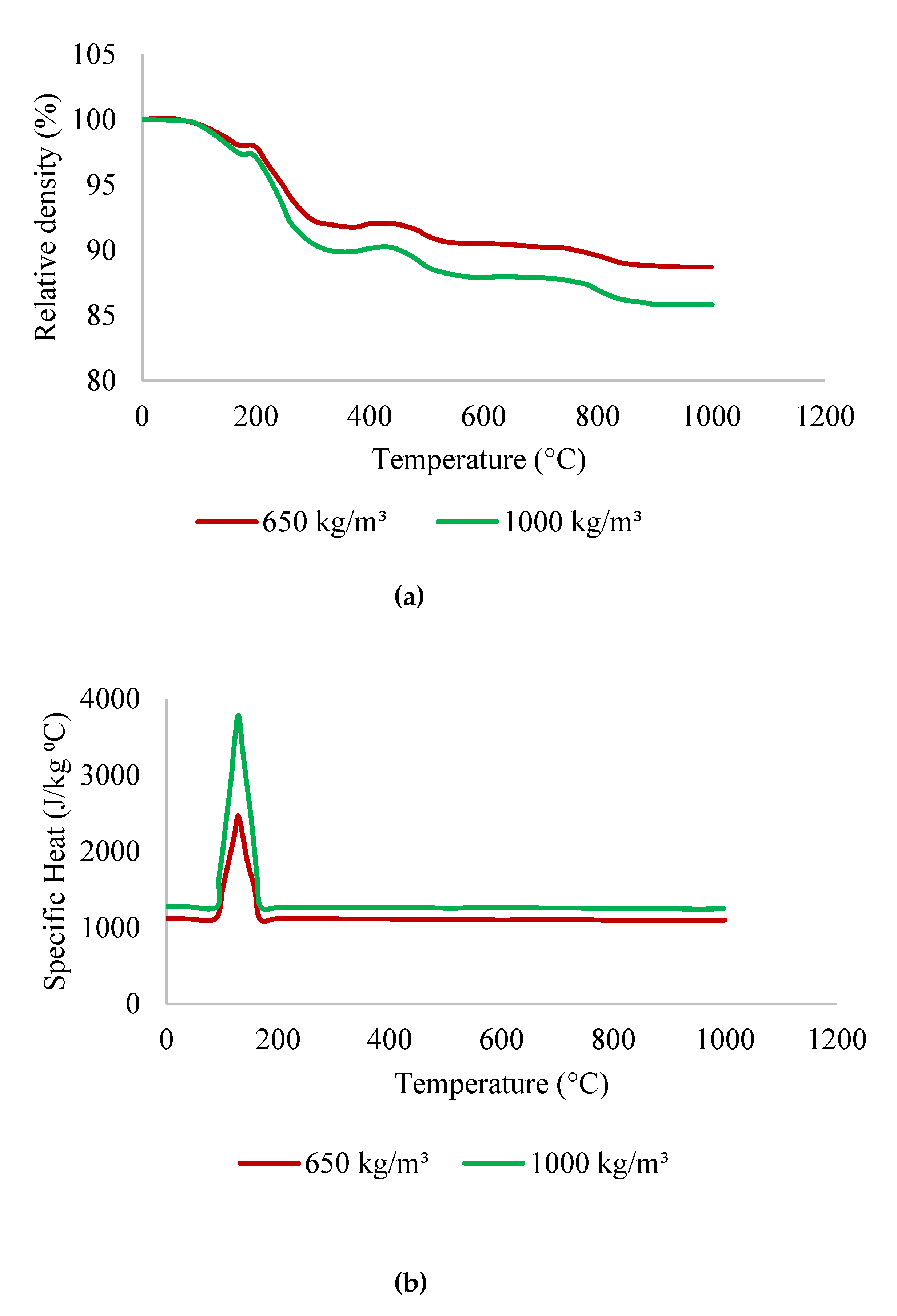
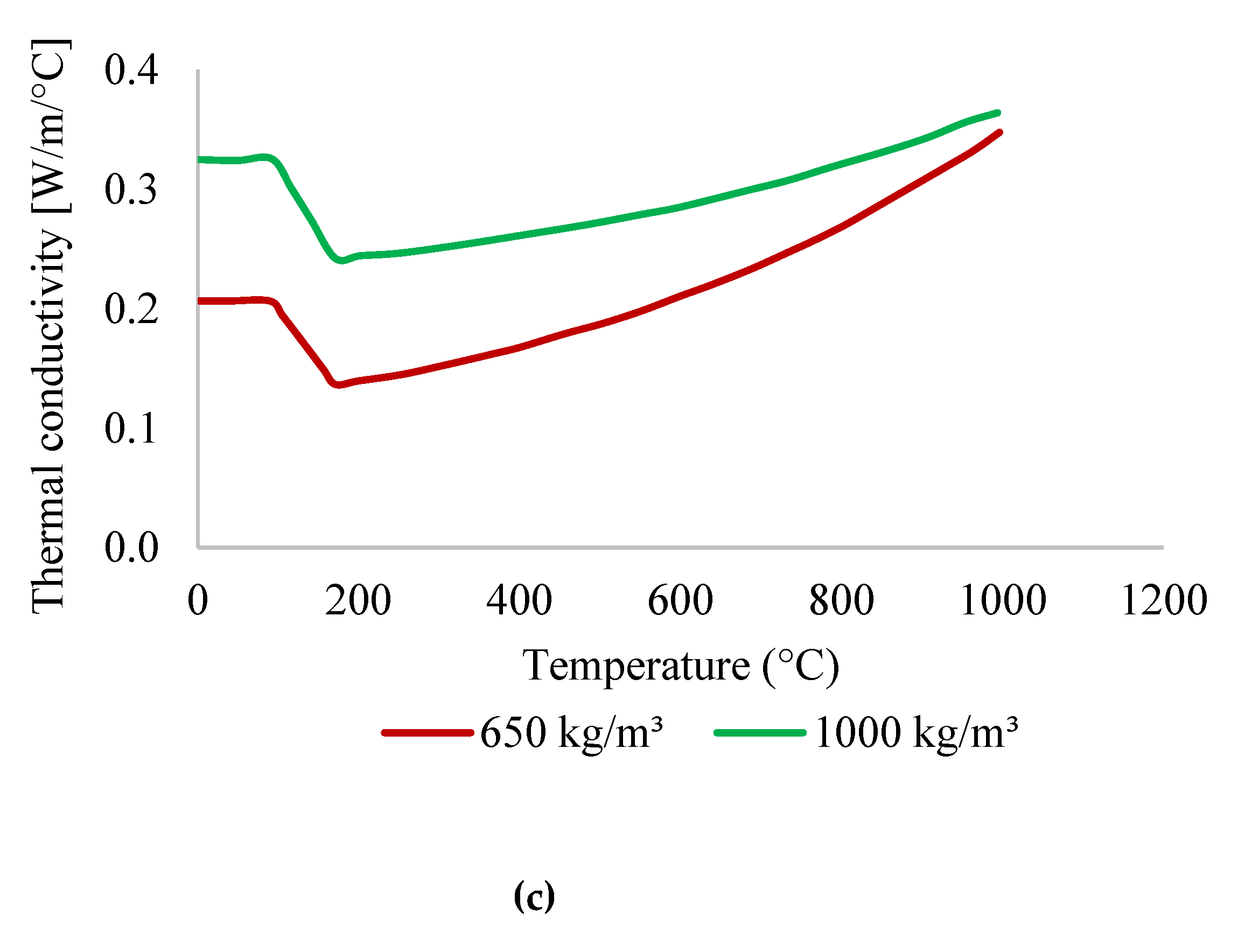
In order to perform the detailed heat transfer analyses of 3DPC non-load bearing wall configurations with and without cavity insulation, precise temperature dependent thermal properties such as thermal conductivity, specific heat, and relative density have to be specified for concrete and the insulation material Rockwool. Alkhalidi and Hatuqay [34] presented the ambient temperature thermal properties of three concrete mixtures used in their study, which were derived from the equation by Craveiro et al. [42]. Since the presented properties are similar to that of the foam concrete at ambient temperature, thermal properties of foam concrete at elevated temperatures have been used in this study. The thermal properties of lightweight foamed concrete (LFC) at high temperatures with densities 650 kg/m3 and 1000 kg/m3 were obtained from the experimental and analytical study by Othuman and Wang [19].
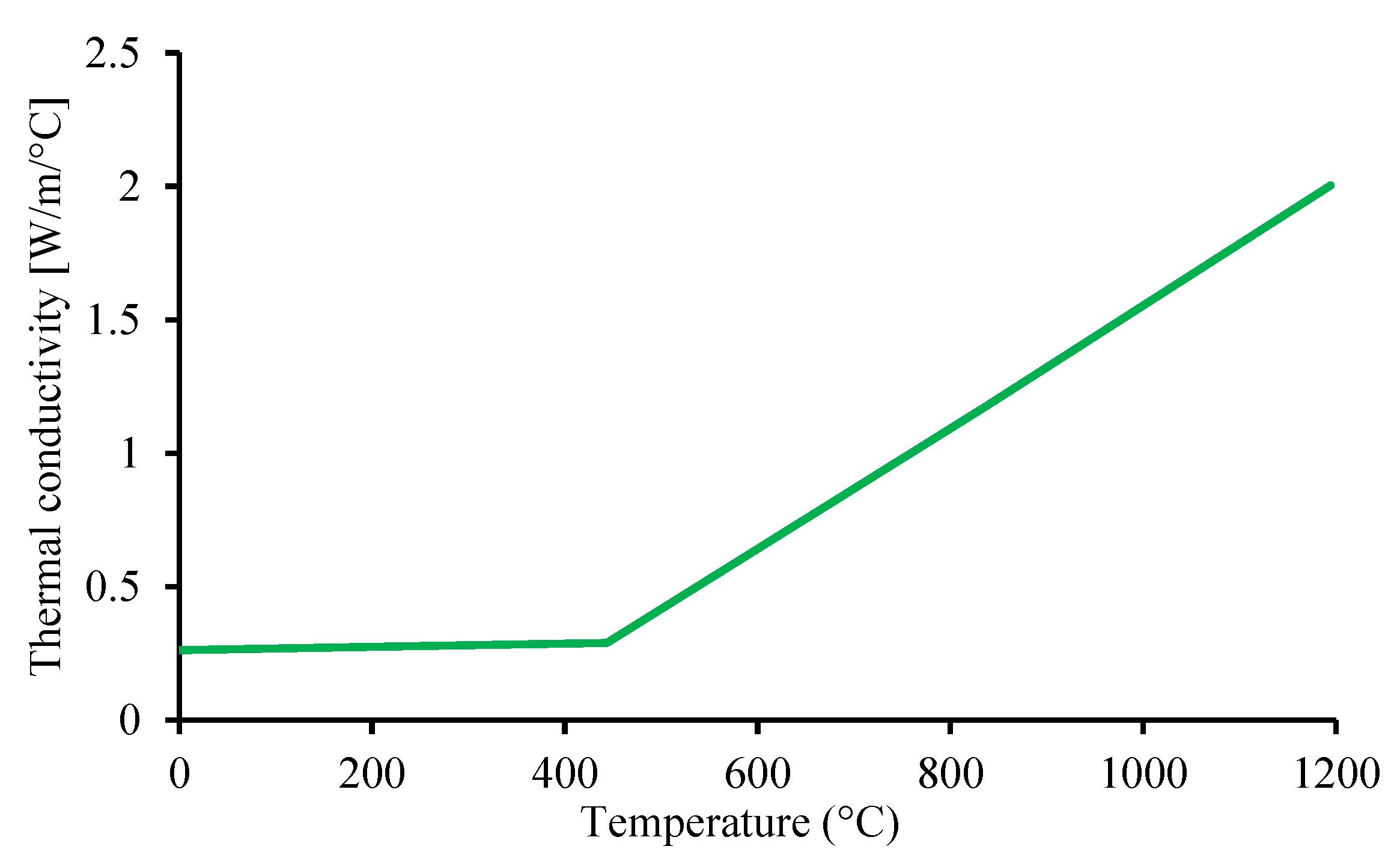
Figure 3a–c shows the thermal properties of foamed concrete at elevated temperatures and Figure 4 illustrates the thermal conductivity variation of Rockwool insulation material. The density and specific heat values of Rockwool at elevated temperatures are 100 kg/m3 and 840 J/kg.°C, respectively [43].

4. Heat Transfer Model in ABAQUS

Thermal loading and boundary conditions were applied to the FE model in a similar pattern to real fire scenario to represent the actual conditions. All three key heat transfer modes conduction, convection and radiation were considered in the developed 3DPC wall models. Thermal loading to the 3DPC vertical wall surface was applied as the boundary conditions. While applying the ambient temperature of 20 °C as the predefined initial temperature for the entire model, time–temperature variation at the fire exposed side of 3DPC wall was applied to follow the standard fire condition. The heat transfer solid 3D eight-node linear brick element with one degree of freedom per node (DC3D8) was used to ensure the conduction heat transfer occurs through the wall element in the same material. The conduction heat transfer by the air inside the cavity is negligible due to its low thermal conductivity. Moreover, convective film coefficient of 25 W/(m2.°C) was used for fire exposed and fire unexposed wall surfaces. The convective heat transfer through the air cavity is also negligible as there is restrictive airflow inside the wall. Therefore, the crucial heat transfer mode within the cavity is considered as radiation. The radiation heat transfer was applied by means of emissivity radiation coefficient to the wall surfaces. An emissivity coefficient of 0.7 was applied on fire exposed and fire unexposed sides of the wall panels and on cavity. The cavity approximation method was also combined to the surface radiation condition of the cavity surfaces. Figure 5 and Figure 6 shows the heat transferring methods of cavity 3DPC walls and the boundary conditions applied on the developed model, respectively. Moreover, the mesh size for each wall configuration was selected considering the convergence of the results. In order to incorporate the continuity among the concrete and Rockwool insulation material for heat transfer, the tie constraint option was used. ABAQUS FE model mesh refinements of cavity wall panels and cavity insulated wall panels are shown in Figure 7a,b, respectively.

5. Validation of Finite Element Model

Verification of any developed model against the available experimental results is vital to ensure the accuracy of the developed models in terms of assumed modifications and the material characterization. This FE heat transfer model was previously validated against the experimental results obtainable by Cicione et al. [31] with modified thermal properties at elevated temperature. The validation was performed for total six (6) 3-D models by comparing the unexposed surface temperature results obtained from the FE analysis with the fire test results from the experimental study. The FE model results were well approved with the experimental results and the detailed validation results have been presented in the studies by Suntharalingam et al. [32,33]. Since, both FE and experimental results showed good agreement, the developed FEM has been extended to investigate the fire performance of 3DPC wall configurations in this study.

6. Parametric Study on 3DPC Wall Panels With Different Configurations

The developed FE heat transfer model was extended to investigate the thermal behaviour of five different wall configurations studied by Alkhalidi and Hatuqay [34]. Those wall panels were integrated with the Rockwool cavity insulation to improve the fire performance and investigated. As per Eurocode standards (EN 1992-1-2, 2017) [44] unexposed surface temperature increment should not exceed 140 °C in average and 200 °C at any point to satisfy the fire resistance in insulation criterion. Insulation fire rating (IFR) of a structural member is identified as the time taken to unexposed surface to achieve 140 °C temperature increments. Hence, the model was used to determine the IFR of developed wall panels.
The parametric study includes twenty (20) wall specimens of five different cross sectional arrangements, two different material densities of 650 kg/m3 and 1000 kg/m3 and walls with and without cavity insulation. The selected configurations and material densities are based on the actual implemented 3D printed walls with 10 cm and 15 cm cavities. The different cross sectional arrangements of wall panels, analysed in this study are shown in Figure 1. The details of parametric study are presented in Table 2.

7. Results and Discussion

The standard fire curve, ISO 834 [
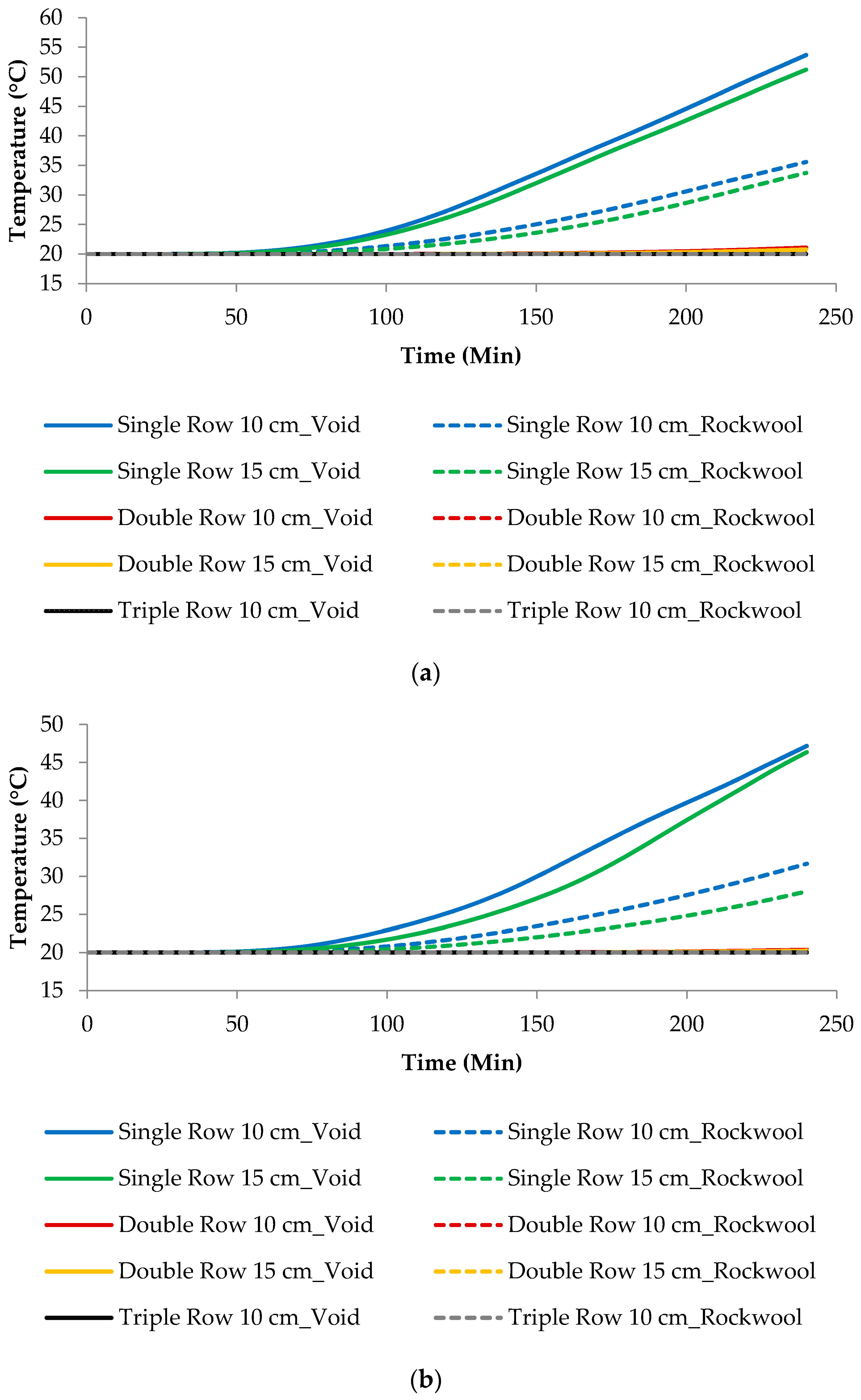
41] was applied on firesides of the heat transfer FE model and the time-dependent fire unexposed side temperature was measured from ABAQUS CAE tools. The fire behaviour of different wall configurations and densities in terms of insulation fire rating are discussed herein extensively.
Figure 8a,b illustrate the unexposed surface temperature variation for all five considered wall configurations with densities 650 kg/m3 and 1000 kg/m3, respectively. Increment in insulation fire rating with the increase in density is clearly identified for all the wall panels. Both the cavity and Rockwool infilled walls showed superior fire resistance such that insulation fire rating is not exceeded the limiting insulation fire rating temperature of 160 °C (140 °C + 20 °C) for all the wall configurations within four hours. Moreover, it is obvious that the temperature increment is very low for the wall configurations with double row and triple row.
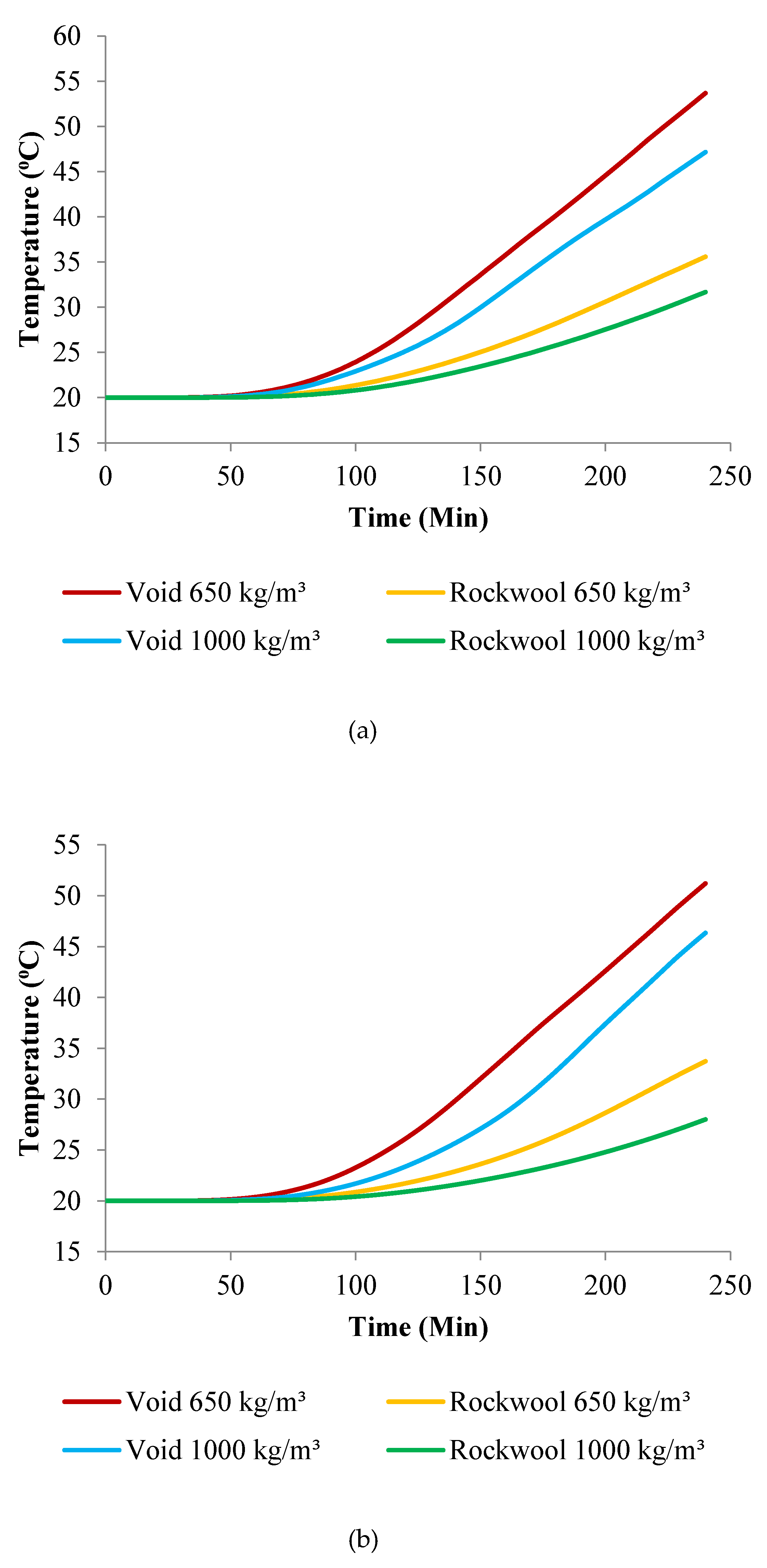
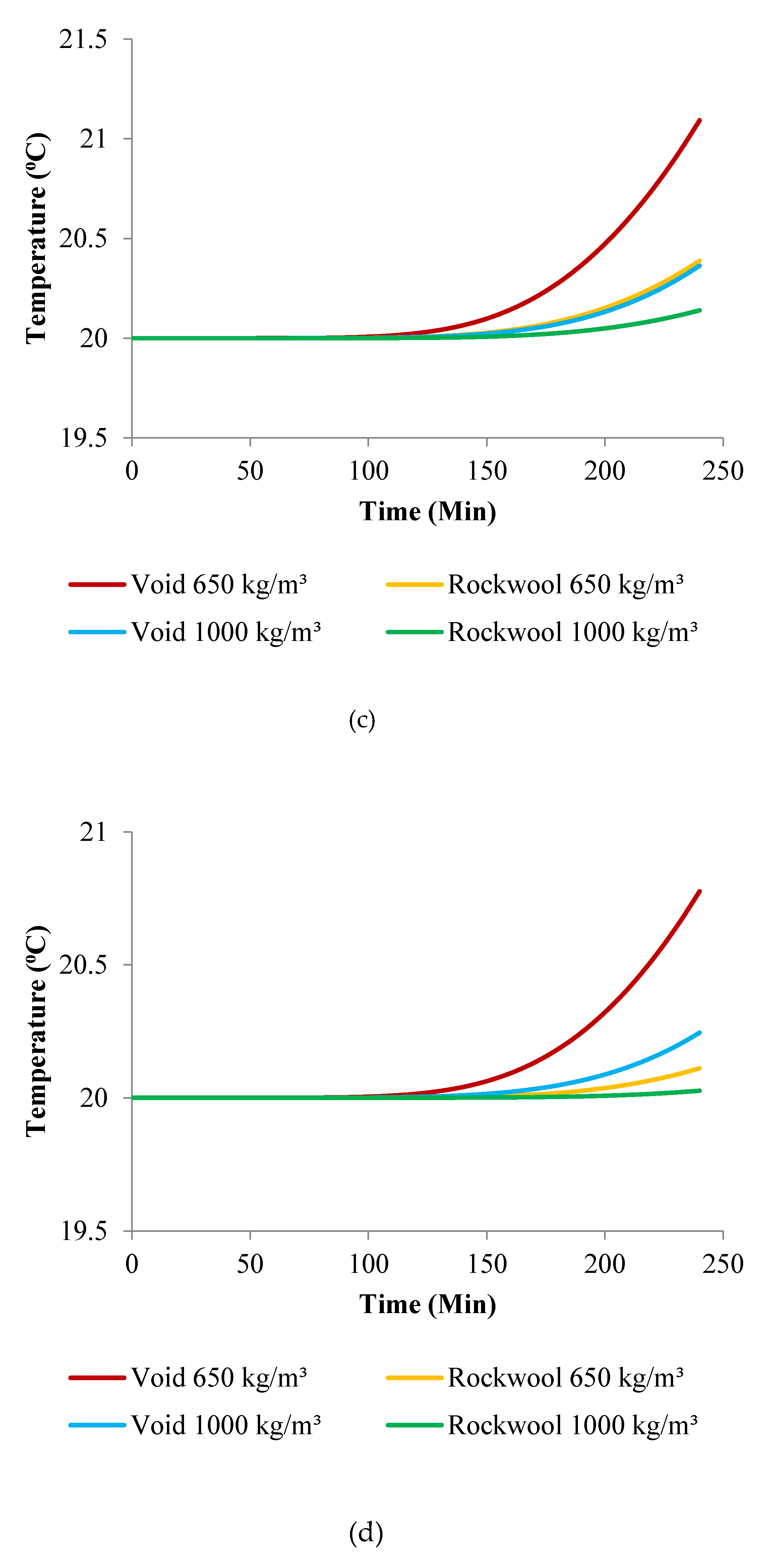
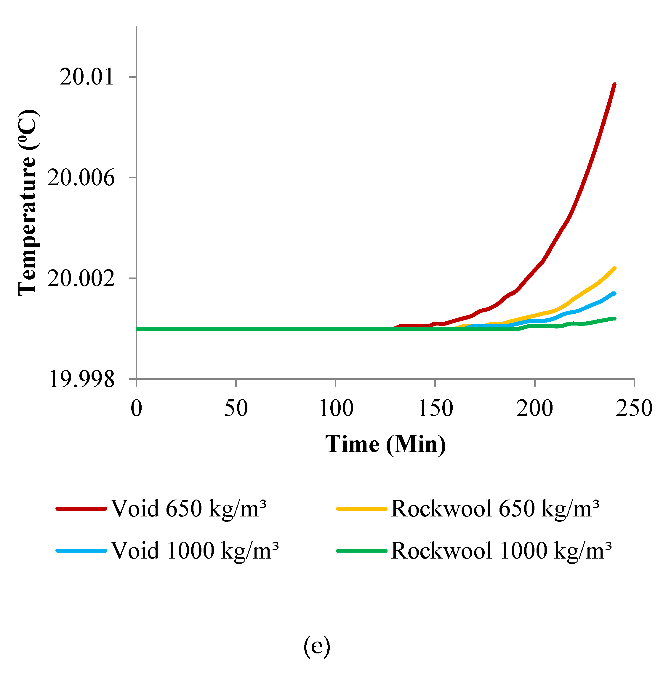
Figure 9a–e illustrate the comparison of unexposed surface temperature variation up to 4 h for all the wall configurations under standard fire condition for varying material densities. The temperature rise of all the different wall configurations in four hours is presented in Table 3. The temperature distribution of the cavity wall panels, and Rockwool insulated wall panels at 0 min, 30 min, 1 h, 2 h, and 4 h of exposure to the standard fire are represented in the Table 4, Table 5 and Table 6.
Considering the results, both the cavity and Rockwool infilled wall configurations have displayed superior fire resistance in terms of insulation failure criteria within the initial four hours. Moreover, increasing fire behaviour is obviously identified with the increase in density for all wall configurations. However, this heat transfer analysis only considers the insulation failure criteria and does not include the combined mechanical–thermal behaviour. Hence, Rockwool insulated single row 10 cm wall configuration with 1000 kg/m3 density could be proposed to have better performance against fire with less material requirement. However, Alkhalidi and Hatuqay [34] proposed E-PLA filled double row 15 cm configuration wall configuration with 1522 kg/m3 density to have higher energy performance. Since, the fire performance will be amplified with increasing wall thickness and density, double row 15 cm configuration wall configuration with density 1522 kg/m3 could be proposed to have energy efficient, thermally comfortable 3D printed built environment with enhanced fire performance.
Moreover, with the aim of developing cost effective sustainable buildings with enhanced structural performance and with increased construction speed the following MBS with 3DPC walls with improved thermal energy and fire performance could be proposed. 
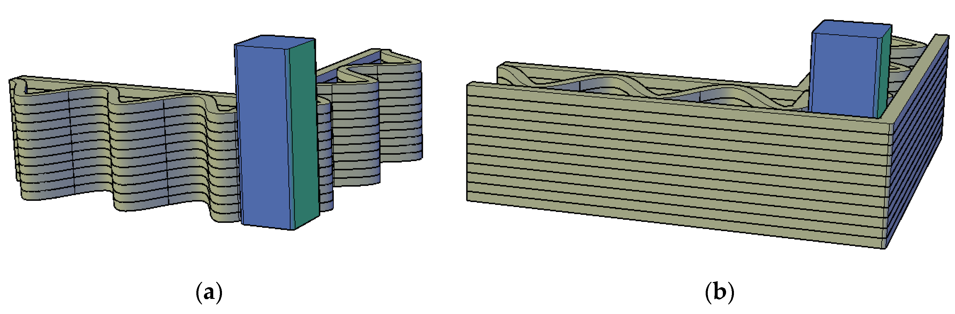
Figure 10 shows one of the proposed 3DPC walls in MBS and Figure 11a,b illustrate the recommendations on how to integrate 3DPC walls around SHS corner posts in steel construction. The configuration shown in Figure 11a illustrates the arrangement of steel corner posts with 3DPC walls. This could be used to protect the steel elements from fire source inside the building which is also easy to install onsite. The in-situ installation of the configuration given in Figure 11b would be a challenge since the corner post t integration with printing process. However, it could be used to protect the steel elements from fire inside the building, as well as external environmental and chemical factors.

8. Conclusions

This paper has given an account of fire performance investigation of different 3DPC wall configurations using heat transfer numerical models. Validated heat transfer models were employed to investigate the fire performance of non-load bearing 3DPC wall configurations, which were already studied for thermal energy performance. A parametric heat transfer finite element analyses were performed with different densities and Rockwool cavity infill. Summarised below are the conclusions that have arisen from this research study.
  • 3DPC non-load bearing cavity walls have substantial resistance under standard fire load for a 4 h exposure time.
  • The unexposed temperature of the double row cavity 3DPC wall configurations remains without any increment even after 4 h of standard fire load. While single row cavity 3DPC walls showed a temperature increment at unexposed side, however, this is well below the insulation fire rating limiting temperature.
  • Introduction of Rockwool as cavity infill showed a superior fire performance compared to cavity 3DPC walls.
  • Significance fire performance improvement was noticed when the thickness of the 3DPC walls increases in a parallel row manner. Similar behaviour was also observed by Alkhalidi and Hatuqay [34] for thermal energy investigation which resulted in a lower U-value for increased thickness of 3DPC walls.
  • Combined thermal energy and fire performance of 3DPC walls can be enhanced increasing the thickness of the wall using parallel row manner and introducing Rockwool insulation as cavity infill.
  • Double row 15 cm configuration wall configuration is proposed to have amplified combined thermal energy and fire performance with less material usage.
  • Integration of 3DPC walls in MBS is proposed as a sustainable solution to modern construction challenges.
This study is the first step towards enhancing the understanding of combined thermal energy and fire performance of 3DPC walls. However, further studies on different mixes and cavity filling materials could be performed for further optimization.

Author Contributions

Conceptualization: K.P.; performed the numerical simulations and analysis: I.U. and T.S.; results interpretation: I.U., P.G., T.S. and K.P.; writing—original draft preparation: T.S., H.R. and P.G.; writing—review and editing: T.S., I.U., P.G., K.P., B.N. and S.N.; visualization: T.S., P.G., H.R., K.P. and S.N.; supervision: K.P. and B.N. All authors have read and agreed to the published version of the manuscript.

Funding

This research received no external funding.

Institutional Review Board Statement

Not applicable.

Informed Consent Statement

Not applicable.

Data Availability Statement

Not applicable.

Acknowledgments

The Authors would like to acknowledge the financial and technical support of Northumbria University, University of Sri Jayewardenepura and RMIT University.

Conflicts of Interest

The authors declare no conflict of interest.

References

  1. Balletti, C.; Ballarin, M.; Guerra, F. 3D printing: State of the art and future perspectives. J. Cult. Heritage 2017, 26, 172–182. [Google Scholar] [CrossRef]
  2. Beyhan, F.; Selçuk, S.A. 3D Printing in Architecture: One Step Closer to a Sustainable Built Environment. Lect. Notes Civ. Eng. 2018, 20, 253–268. [Google Scholar] [CrossRef]
  3. Le, T.T.; Austin, S.A.; Lim, S.; Buswell, R.A.; Gibb, A.G.F.; Thorpe, T. Mix design and fresh properties for high-performance printing concrete. Mater. Struct. 2012, 45, 1221–1232. [Google Scholar] [CrossRef] [Green Version]
  4. De Schutter, G.; Lesage, K.; Mechtcherine, V.; Nerella, V.N.; Habert, G.; Agusti-Juan, I. Vision of 3D printing with concrete — Technical, economic and environmental potentials. Cem. Concr. Res. 2018, 112, 25–36. [Google Scholar] [CrossRef]
  5. Panda, B.; Tan, M.J. Rheological behavior of high volume fly ash mixtures containing micro silica for digital construction application. Mater. Lett. 2019, 237, 348–351. [Google Scholar] [CrossRef]
  6. Buswell, R.; De Silva, W.L.; Jones, S.; Dirrenberger, J. 3D printing using concrete extrusion: A roadmap for research. Cem. Concr. Res. 2018, 112, 37–49. [Google Scholar] [CrossRef]
  7. Kruger, J.; Zeranka, S.; Van Zijl, G. 3D concrete printing: A lower bound analytical model for buildability performance quantification. Autom. Constr. 2019, 106. [Google Scholar] [CrossRef]
  8. Panda, B.; Paul, S.C.; Hui, L.J.; Tay, Y.W.D.; Tan, M.J. Additive manufacturing of geopolymer for sustainable built environment. J. Clean. Prod. 2017, 167, 281–288. [Google Scholar] [CrossRef]
  9. Suiker, A. Mechanical performance of wall structures in 3D printing processes: Theory, design tools and experiments. Int. J. Mech. Sci. 2018, 137, 145–170. [Google Scholar] [CrossRef] [Green Version]
  10. Suntharalingam, T.; Nagaratnam, B.; Poologanathan, K.; Hackney, P.; Ramli, J. Evolution of additive manufacturing technology in construction industry & challenges on implementation: A review. In Proceedings of the 10th International Conference on Structural Engineering and Construction Management, Kandy, Sri Lanka, 12–14 December 2019. [Google Scholar]
  11. Nagaratnam, B.H.; Rahman, M.E.; Mirasa, A.K.; Mannan, M.A.; Lame, S.O. Workability and heat of hydration of self-compacting concrete incorporating agro-industrial waste. J. Clean. Prod. 2016, 112, 882–894. [Google Scholar] [CrossRef]
  12. Banerji, S.; Kodur, V.; Solhmirzaei, R. Experimental behavior of ultra high performance fiber reinforced concrete beams under fire conditions. Eng. Struct. 2020, 208, 110316. [Google Scholar] [CrossRef]
  13. Cao, V.D.; Bui, T.Q.; Kjøniksen, A.-L. Thermal analysis of multi-layer walls containing geopolymer concrete and phase change materials for building applications. Energy 2019, 186, 115792. [Google Scholar] [CrossRef]
  14. Han, L.-H.; Zhou, K.; Tan, Q.-H.; Song, T.-Y. Performance of steel reinforced concrete columns after exposure to fire: Numerical analysis and application. Eng. Struct. 2020, 211, 110421. [Google Scholar] [CrossRef]
  15. Liang, X.; Wu, C.; Yang, Y.; Li, Z. Experimental study on ultra-high performance concrete with high fire resistance under simultaneous effect of elevated temperature and impact loading. Cem. Concr. Compos. 2019, 98, 29–38. [Google Scholar] [CrossRef]
  16. Del Coz-Díaz, J.J.; Martínez-Martínez, J.E.; Alonso-Martínez, M.; Rabanal, F.P. Álvarez Comparative study of LightWeight and Normal Concrete composite slabs behaviour under fire conditions. Eng. Struct. 2020, 207, 110196. [Google Scholar] [CrossRef]
  17. Naus, D.J. A compilation of elevated temperature concrete material property data and information for use in assessments of nuclear power plant reinforced concrete structures [electronic resource] in SearchWorks catalog. Searchworks.stanford.edu, 2020. Available online: https://searchworks.stanford.edu/view/9260707. (accessed on 12 August 2020).
  18. Wakili, K.G.; Hugi, E.; Karvonen, L.; Schnewlin, P.; Winnefeld, F. Thermal behaviour of autoclaved aerated concrete exposed to fire. Cem. Concr. Compos. 2015, 62, 52–58. [Google Scholar] [CrossRef]
  19. Othuman, A.; Wang, Y. Elevated-temperature thermal properties of lightweight foamed concrete. Constr. Build. Mater. 2011, 25, 705–716. [Google Scholar] [CrossRef]
  20. Falliano, D.; De Domenico, D.; Ricciardi, G.; Gugliandolo, E. 3D-printable lightweight foamed concrete and comparison with classical foamed concrete in terms of fresh state properties and mechanical strength. Constr. Build. Mater. 2020, 254, 119271. [Google Scholar] [CrossRef]
  21. Kim, H.; Jeon, J.; Lee, H. Workability, and mechanical, acoustic and thermal properties of lightweight aggregate concrete with a high volume of entrained air. Constr. Build. Mater. 2012, 29, 193–200. [Google Scholar] [CrossRef]
  22. Yang, K.-H.; Lee, K.-H.; Song, J.-K.; Gong, M.-H. Properties and sustainability of alkali-activated slag foamed concrete. J. Clean. Prod. 2014, 68, 226–233. [Google Scholar] [CrossRef]
  23. Chica, L.; Alzate, A. Cellular concrete review: New trends for application in construction. Constr. Build. Mater. 2019, 200, 637–647. [Google Scholar] [CrossRef]
  24. Amran, Y.M.; Farzadnia, N.; Ali, A.A.A. Properties and applications of foamed concrete; a review. Constr. Build. Mater. 2015, 101, 990–1005. [Google Scholar] [CrossRef]
  25. Wei, S.; Yiqiang, C.; Yunsheng, Z.; Jones, M. Characterization and simulation of microstructure and thermal properties of foamed concrete. Constr. Build. Mater. 2013, 47, 1278–1291. [Google Scholar] [CrossRef]
  26. Upasiri, I.R.; Konthesingha, K.M.C.; Poologanathan, K.; Nanayakkara, S.M.A.; Nagaratnam, B. Review on Fire Performance of Cellular Lightweight Concrete. In International conference on Sustainable Built Environment 2018; Lecture Notes in Civil Engineering; Springer: Berlin/Heidelberg, Germany, 2020; pp. 470–478, Chapter 41. [Google Scholar]
  27. Kodur, V. Properties of Concrete at Elevated Temperatures. ISRN Civ. Eng. 2014, 2014, 1–15. [Google Scholar] [CrossRef]
  28. Roy, K.; Lim, J.B.; Lau, H.H.; Yong, P.; Clifton, G.; Johnston, R.P.; Wrzesien, A.; Mei, C.C. Collapse behaviour of a fire engineering designed single-storey cold- formed steel building in severe fires. Thin-Walled Struct. 2019, 142, 340–357. [Google Scholar] [CrossRef]
  29. Steau, E.; Keerthan, P.; Mahendran, M. 10.15: Thermal modelling of LSF floor systems made of lipped channel and hollow flange channel section joists. ce/papers 2017, 1, 2638–2647. [Google Scholar] [CrossRef]
  30. Weng, Y.; Li, M.; Liu, Z.; Lao, W.; Lu, B.; Zhang, D.; Tan, M.J. Printability and fire performance of a developed 3D printable fibre reinforced cementitious composites under elevated temperatures. Virtual Phys. Prototyp. 2018, 14, 284–292. [Google Scholar] [CrossRef]
  31. Cicione, A.; Kruger, J.; Walls, R.S.; Van Zijl, G. An experimental study of the behavior of 3D printed concrete at elevated temperatures. Fire Saf. J. 2020, 103075. [Google Scholar] [CrossRef]
  32. Suntharalingam, T.; Gatheeshgar, P.; Upasiri, I.; Poologanathan, K.; Nagaratnam, B.; Corradi, M.; Nuwanthika, D. Fire performance of innovative 3D printed concrete composite wall panels—A Numerical Study. Eng. Struct. 2021. Under Review. [Google Scholar]
  33. Suntharalingam, T.; Upasiri, I.; Gatheeshgar, P.; Poologanathan, K.; Nagaratnam, B.; Rajanayagam, H.; Nava, S. Fire Resistance of 3D Printed Concrete Composite Wall Panels Exposed to Various Fire Scenarios. J. Struct. Fire Eng. 2021. Peer Reviewed and Accepted. [Google Scholar]
  34. Alkhalidi, A.; Hatuqay, D. Energy efficient 3D printed buildings: Material and techniques selection worldwide study. J. Build. Eng. 2020, 30, 101286. [Google Scholar] [CrossRef]
  35. Hassan, W.H.; Alkhalidi, A. Comparing Between Best Energy Efficient Techniques Worldwide with Existing Solution Implemented in Al-Ahliyya Amman University. Int. J. Therm. Environ. Eng. 2018, 17, 1–10. [Google Scholar] [CrossRef]
  36. Alkhalidi, A.; Qoaider, L.; Khashman, A.; Al-Alami, A.R.; Jiryes, S. Energy and water as indicators for sustainable city site selection and design in Jordan using smart grid. Sustain. Cities Soc. 2018, 37, 125–132. [Google Scholar] [CrossRef]
  37. He, Y.; Zhang, Y.; Zhang, C.; Zhou, H. Energy-saving potential of 3D printed concrete building with integrated living wall. Energy Build. 2020, 222, 110110. [Google Scholar] [CrossRef]
  38. Mohammad, M.; Masad, E.; Seers, T.; Al-Ghamdi, S.G. High-Performance Light-Weight Concrete for 3D Printing. In RILEM International Conference on Concrete and Digital Fabrication; Springer: Cham, Switzerland, 2020; pp. 459–467. [Google Scholar]
  39. Dos Santos, G.H.; Fogiatto, M.A.; Mendes, N. Numerical analysis of thermal transmittance of hollow concrete blocks. J. Build. Phys. 2017, 41, 7–24. [Google Scholar] [CrossRef]
  40. Hibbitt, Karlsson & Sorensen, Inc. ABAQUS; Hibbitt, Karlsson & Sorensen, Inc.: Pawtucket, RI, USA, 1997. [Google Scholar]
  41. ISO 834-1. Part 1: General requirements. Fire-Resistance Tests—Elements of Building Construction; ISO: Geneva, Switzerland, 1999. [Google Scholar]
  42. Craveiro, F.; Bartolo, H.; Gale, A.; Duarte, J.; Bartolo, P. A design tool for resource-efficient fabrication of 3d-graded structural building components using additive manufacturing. Autom. Constr. 2017, 82, 75–83. [Google Scholar] [CrossRef] [Green Version]
  43. Keerthan, P.; Mahendran, M. Thermal Performance of Composite Panels Under Fire Conditions Using Numerical Studies: Plasterboards, Rockwool, Glass Fibre and Cellulose Insulations. Fire Technol. 2012, 49, 329–356. [Google Scholar] [CrossRef] [Green Version]
  44. BSI, E. Part 1–2: General rules—Structural fire design. In EN 1992-1-2: Eurocode 2: Design of Concrete Structures; General Rules and Rules for Buildings; Institution and CEN European Committee for Standardization: Brussels, Belgium, 2008; pp. 1992–1993. [Google Scholar]
Figure 1. Different 3D Printed Concrete (3DPC) cavity wall configurations [34].
Sustainability 13 02314 g001
Figure 2. Cavity fillings effect on U-values obtained at ΔT 40 K printed using Mix 3 [34].
Sustainability 13 02314 g002
Figure 3. Thermal properties of Foamed concrete: (a) Relative density; (b) Specific heat; (c) Thermal conductivity.
Sustainability 13 02314 g003aSustainability 13 02314 g003b
Figure 4. Thermal conductivity of Rockwool [43].
Sustainability 13 02314 g004
Figure 5. Heat transfer mechanism in 3DPC cavity walls.
Sustainability 13 02314 g005
Figure 6. Boundary conditions applied on the model.
Sustainability 13 02314 g006
Figure 7. (a) Mesh refinements of Cavity wall configurations; (b) Mesh refinements of Rockwool insulated wall configurations.
Sustainability 13 02314 g007
Figure 8. (a) Unexposed Surface temperature variation for different wall configurations with density 650 kg/m3; (b) Unexposed Surface temperature variation for different wall configurations with density 1000 kg/m3.
Sustainability 13 02314 g008
Figure 9. (a) Unexposed Surface temperature variation Single Row 10 cm wall configuration; (b) Unexposed Surface temperature variation Single Row 15 cm wall configuration; (c) Unexposed Surface temperature variation Double Row 10 cm wall configuration; (d) Unexposed Surface temperature variation Double Row 15 cm wall configuration; (e) Unexposed Surface temperature variation Triple Row 10 cm wall configuration.
Sustainability 13 02314 g009aSustainability 13 02314 g009bSustainability 13 02314 g009c
Figure 10. Proposed 3DPC wall in modular building system (MBS).
Sustainability 13 02314 g010
Figure 11. 3DPC Wall Element around The Corner post.
Sustainability 13 02314 g011
Table 1. U-value reduction percentages for different configurations at ΔT 40 K (Mix 3—1522 kg/m3).
Wall ConfigurationU-Value (W/m2.K)Reduction % Compared to Single Row 10 cm
Single Row 10 cm1.220
Single Row 15 cm1.202
Double Row 10 cm0.6844
Double Row 15 cm0.6745
Triple Row 10 cm0.4762
Table 2. Parametric Study Outline.
Wall Configuration Density (kg/m3)Insulation TypeNumber of Models
Single Row 10 cm650, 1000Cavity, Rockwool insulation4
Single Row 15 cm 4
Double Row 10 cm 4
Double Row 15 cm 4
Triple Row 10 cm 4
Total 20
Table 3. Temperature rise in 4 hrs of different wall configurations.
Wall ConfigurationsTemperature (°C)
650 kg/m31000 kg/m3
Single Row 10 cmVoid53.6847.16
Rockwool35.5931.67
Single Row 15 cmVoid51.2146.34
Rockwool33.7328.01
Double Row 10 cmVoid21.0920.36
Rockwool20.3920.14
Double Row 15 cmVoid20.7820.24
Rockwool20.1120.03
Triple Row 10 cmVoid20.0120.00
Rockwool20.0020.00
Table 4. Temperature contours of single row 10 mm wall at different time intervals.
Single Row 10 cm Cavity WallSingle Row 10 cm Rockwool Insulated Wall
Sustainability 13 02314 i001 Sustainability 13 02314 i002
Sustainability 13 02314 i003 Sustainability 13 02314 i004
Sustainability 13 02314 i005 Sustainability 13 02314 i006
Sustainability 13 02314 i007 Sustainability 13 02314 i008
Sustainability 13 02314 i009 Sustainability 13 02314 i010
Table 5. Temperature contours of double row 10 mm wall at different time intervals.
Double Row 10 cm Cavity WallDouble Row 10 cm Rockwool Insulated Wall
Sustainability 13 02314 i011 Sustainability 13 02314 i012
Sustainability 13 02314 i013 Sustainability 13 02314 i014
Sustainability 13 02314 i015 Sustainability 13 02314 i016
Sustainability 13 02314 i017 Sustainability 13 02314 i018
Sustainability 13 02314 i019 Sustainability 13 02314 i020
Table 6. Temperature contours of triple row 10 mm wall at different time intervals.
Triple Row 10 cm Cavity WallTriple Row 10 cm Rockwool Insulated Wall
Sustainability 13 02314 i021 Sustainability 13 02314 i022
Sustainability 13 02314 i023 Sustainability 13 02314 i024
Sustainability 13 02314 i025 Sustainability 13 02314 i026
Sustainability 13 02314 i027 Sustainability 13 02314 i028
Sustainability 13 02314 i029 Sustainability 13 02314 i030
Publisher’s Note: MDPI stays neutral with regard to jurisdictional claims in published maps and institutional affiliations.

