
Aircrafts On-Ground Dynamics Models and Simulation Software: State-of-the-Art


Research Center for Territory, Transports and Environment, Department of Civil Engineering, University of Coimbra, 3030-788 Coimbra, Portugal
*
Author to whom correspondence should be addressed.
Sustainability 2021, 13(16), 9147; https://0-doi-org.brum.beds.ac.uk/10.3390/su13169147
Submission received: 12 July 2021
/
Revised: 4 August 2021
/
Accepted: 11 August 2021
/
Published: 16 August 2021
(This article belongs to the Special Issue Pavement Energy Harvesting and Sustainability)
Abstract
:The aircraft is a means of transportation that operates mainly in the air; however, it starts and ends its journey on the ground. Due to the aircraft’s structural complexity, simulation tools are used to understand and to predict its behavior in its movements on the ground. Simulation tools allow adjusting the observation parameters to gather a greater amount of data than real tests and explore interactions of the aircraft and their individual components with external objects such as pavement imperfections. This review aims to collect information on how to simulate the aircraft interaction with traffic-dependent energy harvesting systems. The specifications and framework to be met by a conceptual design are explored. The different configurations for simulating the aircraft configuration result in the selection of the two-mass-spring-damper model. For the components, especially the landing gear, a deployable element for on-ground movements, several existing models capable of translating the tire are also presented, resulting in a selection of point-contact, Fiala and Unified semi-empirical models. It is verified which software can address the proposed simulation, such as GearSim from SDI-Engineering and Matlab/Simulink/Simscape Multibody from MathWorks.
1. Introduction
Due to the complexity of an aircraft’s systems, its ground contact is not straightforward [1]. The aircraft behavior on the ground maneuvers develops dynamic loads focusing on the landing gear [2,3].
Given the aircraft’s entire structure, the landing gear dimensioning appears as a starting point given the importance of this aircraft component. This complex system must meet goals that are sometimes contradictory. The landing gear must support the aircraft’s weight and the dissipation of potential and kinetic energy when it lands and provide safety and comfort in various types of pavement and airport conditions. The landing gear must meet the requirements optimized for its weight, impacting this vehicle’s performance and economic factors [4].
Both the aircraft and the airport pavement follow a set of specifications to ensure safety in their use. These specifications originated in FAR-25 (for the United States), with adaptations to the CS-25 (for the European Union) and CCAR-25 (for China) for large aircraft, similar to other types of aircraft. The ICAO (International Civil Aviation Organization) drives the standards for airfield pavement with PCN (Pavement Classification Number) and ACN (Aircraft Classification Number). PCN expresses the load-carrying capacity of pavement, and ACN represents the effect of an aircraft on a pavement structure [5].
The FAR-25, CS-25 (based indirectly to FAR-25 thru JAR-25 [6]), and CCAR-25 (identically to FAR-25 [7]) highlight the limit of aircraft descent up to 10 ft s−1 (feet per second) or 3.05 m s−1 (meters per second) for commercial aircrafts onto the runway. The ICAO ACN-PCN standardizes airfield pavement’s safe and efficient use by translating its strength [5]. Based on these data provided by the standards, aircraft manufacturers need to adjust their landing gears to meet the safety and certification requirements [8]. Additionally, the ACN-PCN method also allows the design of the airfield pavement for the defined operational time [9,10].
The standard-based airport aircraft-pavement framework can be interpreted using simulation. Simulation allows searched data to be obtained; otherwise, proceeding with the real-world testing would require more financial effort and a high number of sensors to make data collection possible, which may be very laborious [11]. This review seeks to address models, formulation, and simulation software and what features they address. This review continues the work carried by Correia and Ferreira [12].
2. Aircraft On-Ground Dynamics Models
2.1. Introduction
Models are an essential part of the process of characterizing real data. The model’s choice should be based on its ability to translate the real data into what it is intended to analyze. In this study, the models analyzed will be those capable of solving the aircraft’s ground movement in the airport infrastructure (regarding pressure, force, velocity).
The airport pavement can be built with different materials and have various maintenance statuses that the aircraft should support, through its landing gear, without demeriting the safety and comfort of passengers or cargo according to the FAR-25, CS-25, and CCAR-25 standards. For this, it is necessary to analyze the components that will interact, in the first instance, with the pavement, and the possible elements in it, i.e., the tires. Although there is considerable research for the study of car tires [13,14], it is essential to understand the differences between car and aircraft tires. Wesołowski et al. [15], noting the scarcity of tests regarding aircraft tires, conducted extensive laboratory tests. After performing those previously referred tests, the authors concluded that the theoretical formulation analyzed differs from the laboratory tests results obtained, claiming that future trials will allow them to develop a better theoretical model [15].
Doyle, Jr. [16] had referred that “central to any dynamic analysis is the extent to which the motions of the system are included in the model, i.e., which degree of freedom (DOF) are necessary to accurately predict the phenomena being investigated”. Different models from twelve nonlinear DOF models to two linear DOF models can be used [17].
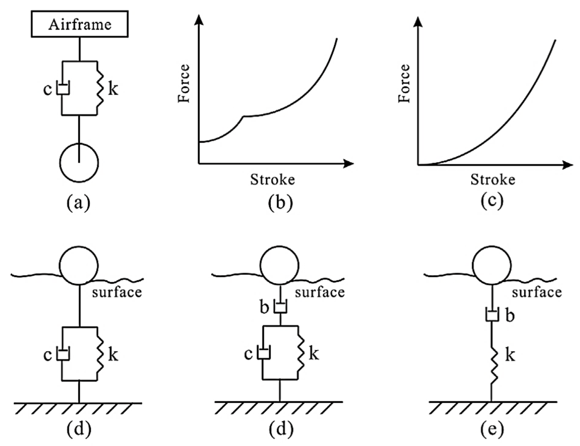
Yang et al. [18] selected the six DOFs, the vertical degrees of freedom, referring to the most usual way of modeling the airframe. In addition to airframe modeling, suspension, tires, and pavement modeling should be added [16,18]. The suspension typically comprises a linear spring k and a damper c in parallel (Figure 1a). The suspension is modeled as a nonlinear spring (Figure 1b) and velocity squared dampers (Figure 1c). The authors also propose the prediction of soil rutting (Figure 1d,e) by adding a rebound b degree, which is present in soils [18].
The landing gear and the aircraft tires become prominent during takeoff and landing [19]. It is essential to ensure that any new components on the runway or traffic paths are within the aircraft’s components’ tolerance range.
The ICAO [5] states that irregularities may exist due to aircraft operations and the laying of pavement foundations. Pavement irregularities impact the various structural systems of the aircraft and its occupants differently. Depending on the type of aircraft and the speed at which it encounters a pavement irregularity, the maximum allowable values of this irregularity are variable. For standardizing purposes, the maximum values for these irregularities are dependent on the length at which they occur. The Boeing Bump Index is used to calculate the maximum value of the irregularity in the pavement [20], expressed in the following equation:
where
- = Bump height (cm);
- = Bump length (m).
For this, it is also necessary to analyze the part that will interact, in the first instance, with the pavement, and possible elements in it, such as the tires. Then, the suspension and finally the aircraft motion can be considered.
2.2. Tire
Although there is considerable research for the study of car tires [13,14], it is essential to understand the differences between car and aircraft tires. Kiébré [21] refers that “aircraft tyres and most ground vehicle tyres are relatively similar in structure and shape”. The author states that although there are similarities mentioned above, the characteristics of the material used are different because the operating conditions are also different. Vehicle tires can be for commercial or cargo vehicles where high weight support is required but with low speed, or for light cars or sports cars that reach high speed but with a lower weight. Aircrafts need the tire to support a high load at high speed [21].
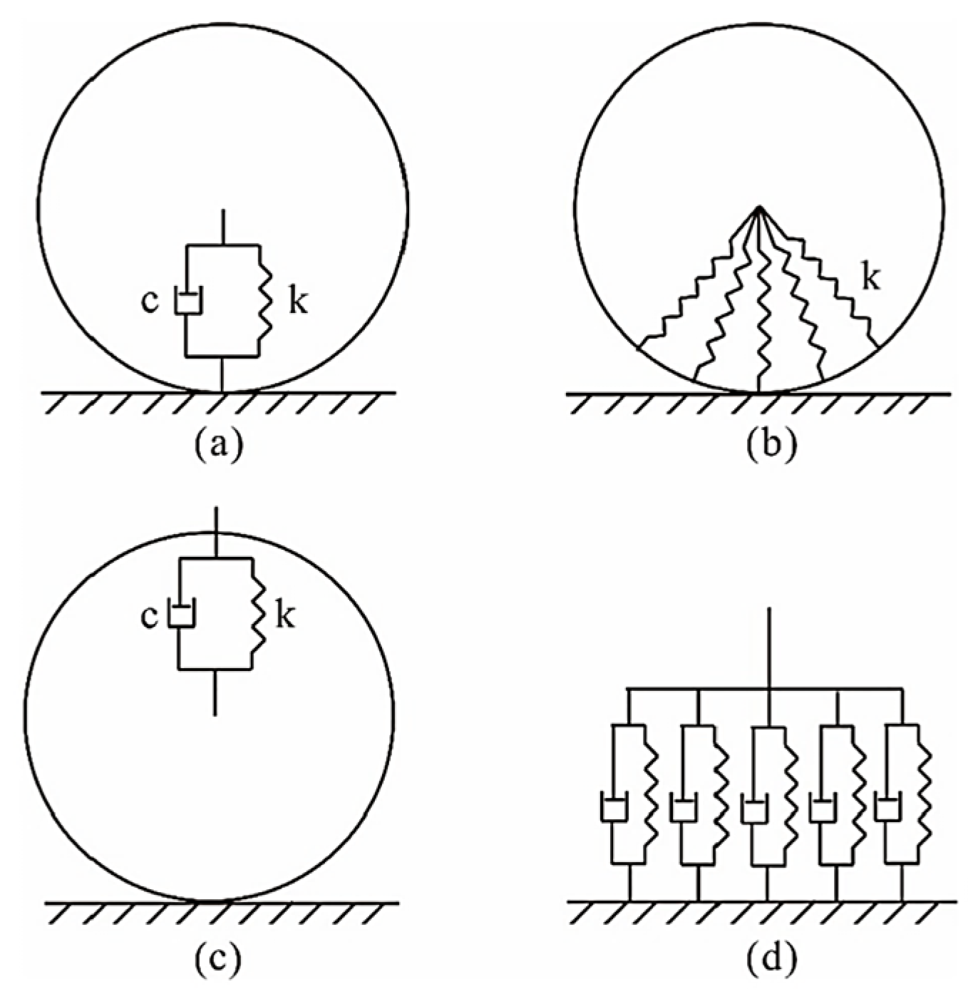
Yang et al. [18] summarize several existing methods for the characterization of the aircraft tire, starting with the point contact theory, capable of relating the tire strength and moment [22]. The point contact theory is composed by a spring k and a dashpot c in parallel, as shown in Figure 2a. In Figure 2b, the radial spring model, the tire is simplified in elastic strings k connected to a central point [23]. The rigid band model, Figure 2c, does not provide for the vertical restriction between the point of contact with the pavement and the center of the wheel [24]. In the rigid band model, the tire is also modeled by a parallel of spring k and dashpot c [18]. Figure 2d shows the fixed footprint model and results from the linear distribution of the contact zone between the tire and the pavement.
Kilner [25] presented the toroidal membrane tire model to predict the vertical load, and horizontal resistance derived from irregularities in the pavement, such as speed bumps and potholes. Despite the good results with the spring tire model, the toroidal membrane tire model requires a large amount of data, and all sections of the tire are assumed to be independent.
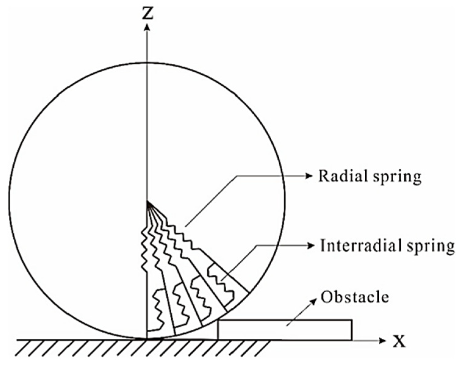
Badalamenti and Doyle [26] present a model capable of joining the previously independent elements, and the radial–interradial spring tire model is illustrated in Figure 3.
The radial–interradial spring model, in linear form, can be expressed as:
Equation (2) allows for obtaining the vertical force, Fv, due to N elements’ displacement. Thus, it is necessary to provide the radial displacement, Evi, and the spring C1 constants from the force–deflection curve and k from the simultaneous equations.
Compared with test measurements, better results are achieved by adding the quadratic radial spring constant, C2, to the Equation (2), resulting in:
- Semi-empirical models—Model of Smiley and Horne [36]; Somieski model [37]; Model of Shim and Margolis [38]; Unified semi-empirical model [39]; Model of Dugoff [40]; Model of Kamm [27]; Nicolas and Comstock model [41]; Model of Rimondi and Gavardi [42]; Model of Schieschke [43]; Magic Formula [13]; FTire [44];
Kiébré [21] refers to the complexity of the tire structure, behavior, and the particularity of each model. It also mentions that the company Messier-Dowty (acquired by Safran Landing Systems [49]) uses the Fiala model, adding Magic Formula analysis as a semi-empirical model for analysis [21].
Cosin Software [50], an FTire [44] development company, which has some models of tires for vehicles (cars and trucks), informs that it has recently started to survey the characteristics of a model of an aircraft tire. This work began in partnership with a tire manufacturer in the area. There is still no forecast for the finalization of this model.
It is crucial to conclude that the models mentioned above allow the tire to be characterized in several components, verifying the lateral force. This review and future work consider this force, the lateral force, null because it is considered that the aircraft is already stabilized on the pavement. The movement is straight forward and so, only longitudinal forces exist. Despite this consideration, the point-contact, Unified semi-empirical, Fiala, and Magic Formula models are selected, the last two already in the MathWorks software [51]. The Magic Formula may not be possible due to the lack of information to determine the required values. The Fiala model is shown to characterize the desired behavior [52]. The unified semi-empirical model is selected due to the number of values needed to represent the tire’s forces [39].
Further considerations on this document will be only based on the point–contact model for document clarity.
2.3. Suspension
Currey [53] refers that “there are two basic types of shock absorbers: those using a solid spring made of steel or rubber and those using a fluid spring with gas or oil, or a mixture of those two that is generally referred to as oleo-pneumatic”. The author points out that the choice of suspension type is based on the contrast between the operations and economics.
Despite the existence of rigid, rubber, leaf spring, and liquid spring shock absorbers, commercial airplanes typically use oleo-pneumatic shock absorber suspension systems due to their efficiency [1,2,53].
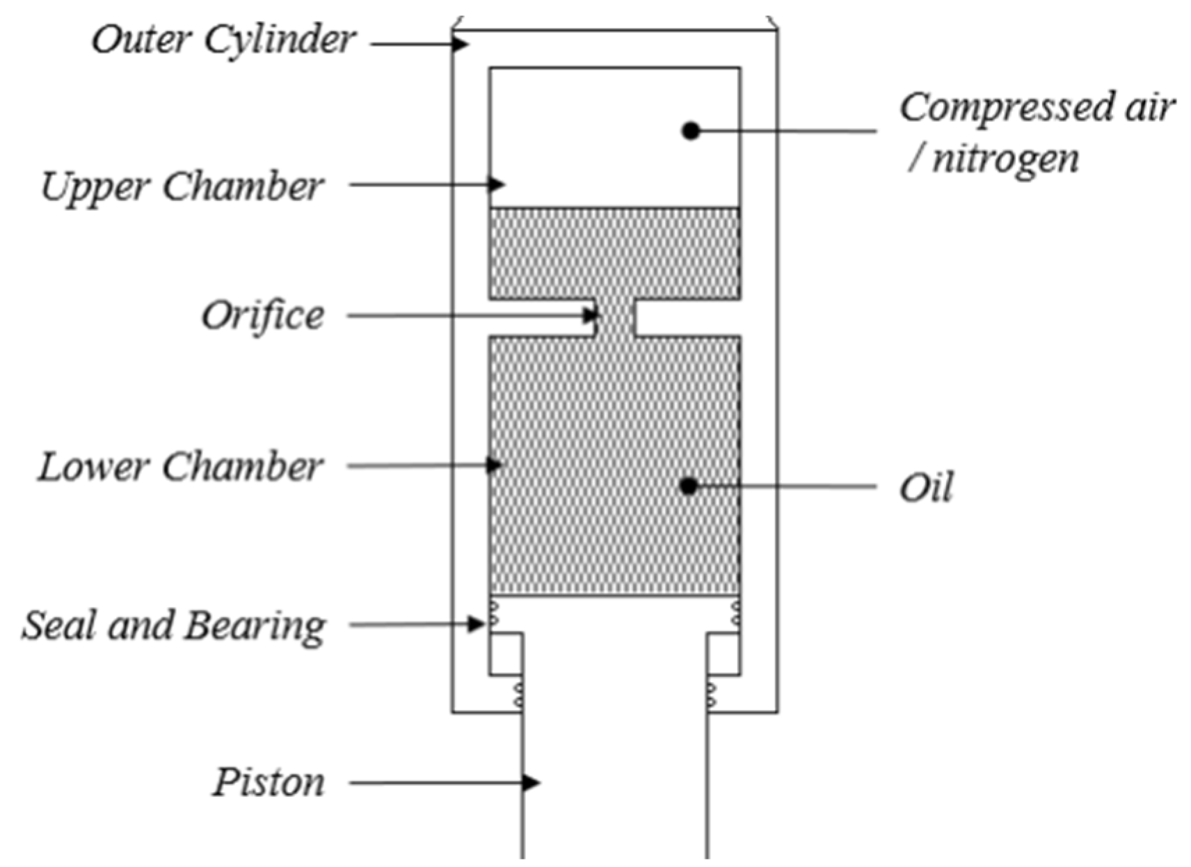
The oleo-pneumatic system can be translated into spring-damper with nonlinear behavior. In general terms, the oleo-pneumatic system uses air (or gas) compression to have a spring behavior and oil passing in an orifice between chambers for the damper behavior. Figure 4 presents an oleo-pneumatic shock-absorber cylinder, also known as “oleo”.
The spring and damper values can be obtained from the manufacturer, however, if it is impossible to get them, they can be calculated [11,53]. The spring and damping values for the previously referred oleo-pneumatic cylinder use the following equations [53,54,55,56]. For the nonlinear spring is used the gas stiffness [53,54] formulated as:
where
- = Spring force (N/m);
- = Pressure inside the shock strut (Pa);
- = Adiabatic gas constant of the nitrogen;
- = Area of the shock strut cylinder (m2);
- = length of the shock strut (m);
- = Piston position (m).
For the nonlinear damping, Equation (6), the mass conservation law is used, with the input of Bernoulli’s equation, Equation (5) [55,56]:
where
- = Force of the liquid (N);
- = Density of the hydraulic fluid (kg/m3);
- = Area of the shock strut cylinder (m2);
- = Piston position (m);
- = Discharge co-efficient of the orifice;
- = Area of the orifice (m2);
- = Damper Force (N/(m/s2)).
The friction force in the oleo-pneumatic can also be added [56]:
where
- = Friction force (N);
- = Friction coefficient;
- = Piston position (m).
3. Aircraft On-Ground Motion Equation
3.1. Introduction
This review aims to understand and simulate the interaction behavior of a rigid aircraft with energy harvesting devices embedded into the pavement. Because the airport pavement is ideally built with no longitudinal inclination, the aircraft pitch along the pavement is taken into account as 0º in this analysis. The aircraft pavement pitch is also taken to be null given the maximum height of the energy-harvesting equipment versus the distance between the NLG (nose landing gear) and the MLG (main landing gears).
Due to the considerable distance between the left and right MLG sets, aircraft roll is not considered. The previously mentioned sets are actuated simultaneously, reinforcing the possibility of discarding the aircraft roll. Due to sensitivity analysis, the location of the energy harvesting device will not be in the impact zone of the aircraft or steering, so it will not be necessary to analyze the lateral force.
The following equations quantify the kinetic and potential energy of the aircraft:
where
- = Kinetic energy (J);
- = Mass (kg);
- = Velocity (m/s);
- = Rotational energy (J);
- = Moment of inertia (kg.m2);
- = Angular velocity (rad/s);
- = Tire radius (m);
- = Potential energy (J);
- = Gravitational acceleration (m/s2);
- = Height (m).
They can be summed in mechanical energy, , as:
3.2. Tricycle Configuration
Lemay et al. [57] had referred that “a grounded short haul aircraft is a tricycle vehicle with symmetric MLG (main landing gears) and a unique steerable NLG (nose landing gear)”. The authors also explain that the main landing gears, or undercarriage, are driven and braked while the nose landing gear is only free rolling. It can adopt simplified models when the aircraft is taxiing, suitable for the reduced roll dynamics.
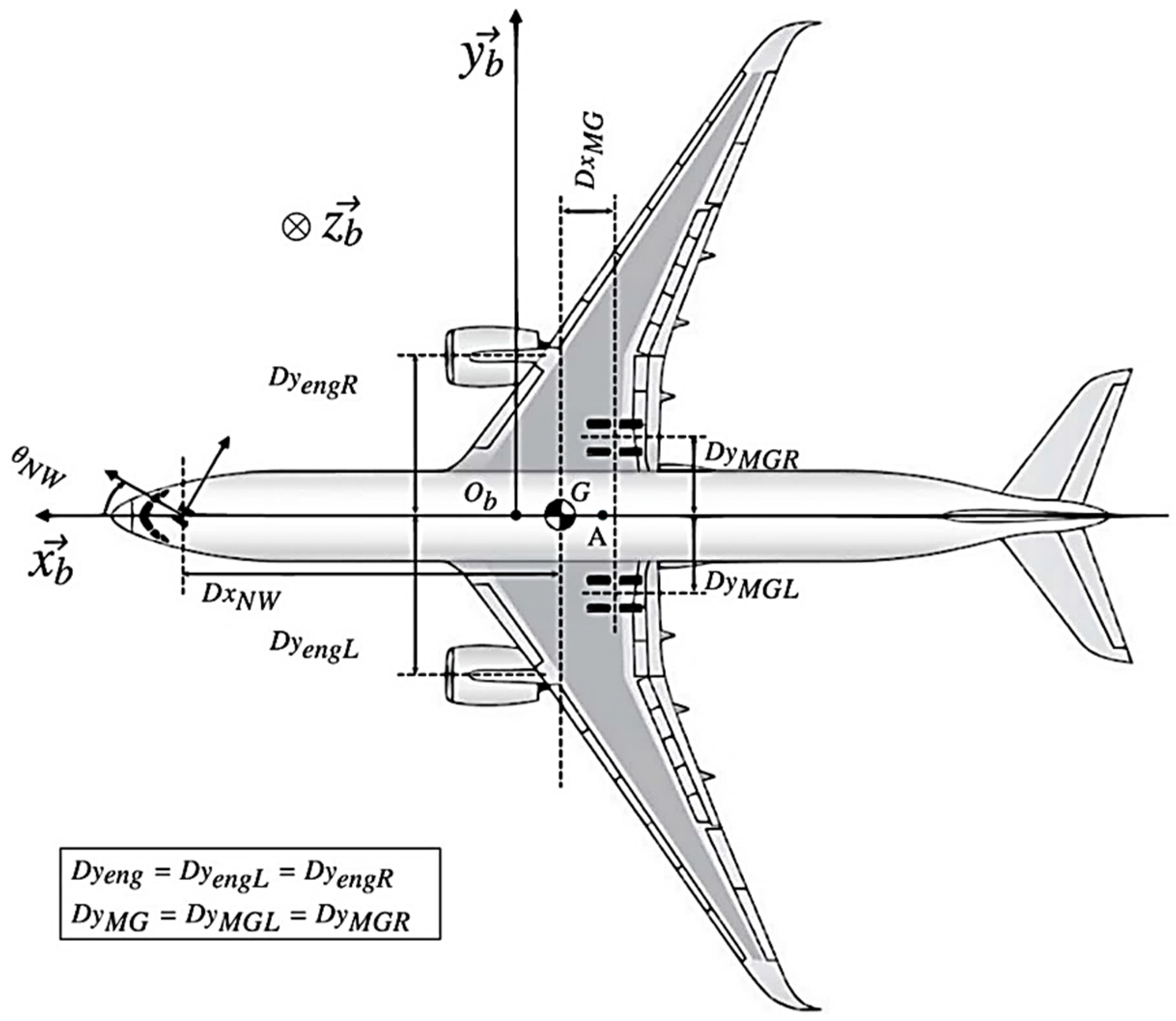
Sadien et al. [58] propose a three DOF model that includes longitudinal and lateral aerodynamic forces, tire-to-ground interactions, the vertical load, and the runway status. Actuators are also considered in the researchers’ model. For this model, a simplification, in addition to others, of tricycle configuration was used. Another consideration was the linearization of the aerodynamic effects, with a reduced lateral inclination angle, a maximum crosswind of 5.14 m/s, and a maximum speed of 185 km/h. The simplified parameters allow calculating the Fza value and the ability to consider the following figure (Figure 5).
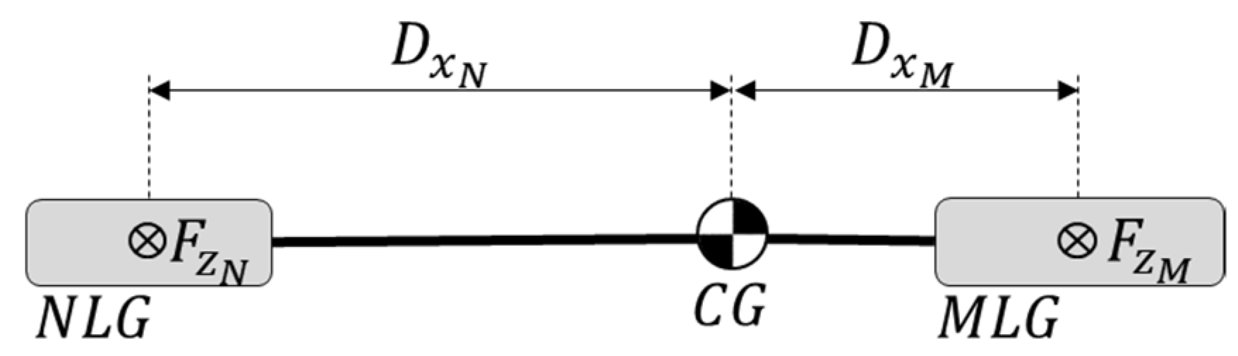
Most commercial aircrafts feature three landing gears, and all tires have, ideally, the same values in the load distribution and the same status in the landing gear. The tires support the vertical force, Fz, and the aircraft has mass m. The Dx values correspond to the distances referred to Figure 5, and cx has assumed dimensionless coefficients, resulting in the following equations:
3.3. Bicycle Configuration
The aircraft can be described, in its dynamic component, by a bicycle configuration [57], which represents a more simplified configuration. The use of this configuration assumes that all wheels located on the same axle are one. The aircraft, as a bicycle configuration, is presented in Figure 6.
It is essential to consider that Equations (14)–(17) only assume the vertical forces applied to the wheel. Only the vertical force is selected since it is the one used in the following model.
3.4. Two Mass-Spring-Damper Model
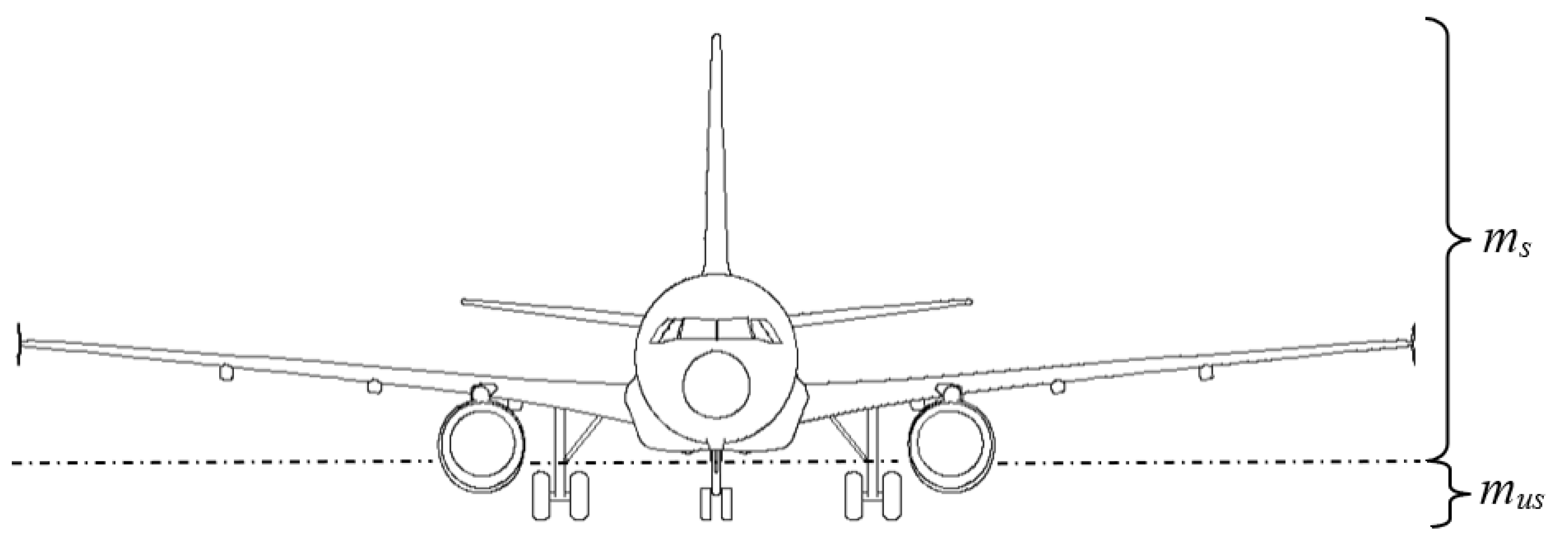
The aircraft mass, based on Equations (14)–(17), is divided into two components: the sprung mass (ms) and the unsprung mass (mus), both represented in Figure 7.
The sprung mass is the mass of the body of the aircraft. The unsprung mass is the tire or tires’ mass. The suspension separates the two masses, and their behavior can be translated using the two-mass-spring-damper equation model, a two DOF model.
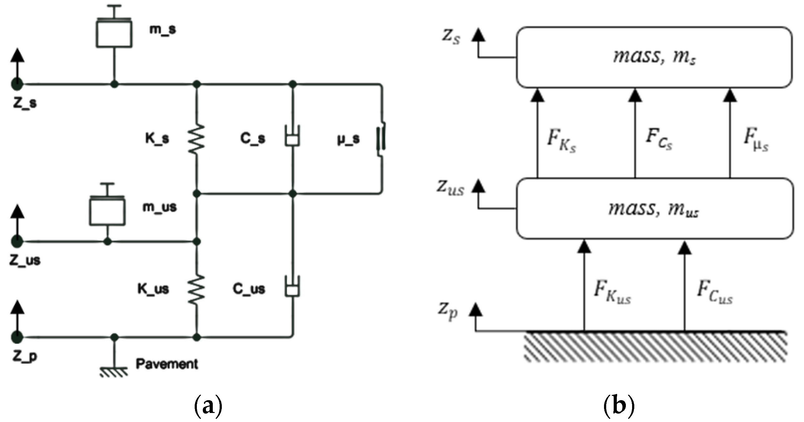
The two-mass-spring-damper equation model evokes the categorization of the aircraft by joining Figure 1a and Figure 2a, i.e., associating the aircraft mass with the suspension system and the tire. Although not mentioned in the previously referred models, the friction force in the oleo-pneumatic system is added to better describe the component [56]. The result of the aforementioned model is presented in Figure 8.
Figure 8a presents the components of the rigid body aircraft, and Figure 8b presents the forces. The following formulation is then created, which will allow the equation of motion of the aircraft formulation and its iteration with the pavement and their vertical displacement:
where
- = Spring force of the sprung mass (oleo-pneumatic) (N);
- = Damping force of the sprung mass (oleo-pneumatic) (N);
- = Friction force of the sprung mass (oleo-pneumatic) (N);
- = Spring force of the unsprung mass (tire) (N);
- = Damping force of the unsprung mass (tire) (N);
- = Spring coefficient (oleo-pneumatic) (N/m);
- = Damping coefficient (oleo-pneumatic) (N/(m/s));
- = Friction coefficient (oleo-pneumatic) (N);
- = Spring coefficient (tire) (N/m);
- = Damping coefficient (tire) (N/(m/s));
- = Position of the sprung mass (m);
- = Position of the unsprung mass (m);
- = Position of the reference (m).
Using the 2nd Newton’s law:
where
- = Force (N);
- = Mass (Kg);
- = Acceleration (m/s2).
Applying the Equations (18)–(20) and (23) to the sprung mass:
Applying Equations (18)–(23) to the unsprung mass:
Equation (34) is a matrix form of Equations (28) and (33) and represents the model:
4. Simulation Software
Simulation software is used to better understand the aircraft’s iteration, especially the landing gear and the airport pavement. Simulation software allows for designing the various aircraft structures at a more reasonable and safer cost. Simulation opens up the opportunity to make multiple changes to the system by checking its response. For existing products, it sustains the understanding phenomena that had occurred. Those tools also support the new generation of commercial aircraft requiring revision to airport pavement design, which can be overcome with simulation software [59,60]. The computation evolution brings simulation nearest to the final product to such an extent that they form a part in the certification process [4].
Simulation software makes it possible to explore various constructions to optimize the total system’s final performance. The use of simulators enhances the analysis of multiple characteristics without purchasing, installing, and calibrating physical measuring devices, making it more economical and logistically more accessible to perform the tests. The use of simulation also allows for various scenarios as intended in the analysis. For obtaining data, the simulator enables working in a safe environment regardless of the factors analyzed.
This section is focused on software for simulating the aircraft’s on-ground dynamics that allow an analysis of the components. During this state of the art, some software capable of accomplishing such needs were raised, leaving the next phase’s selection.
When the aircraft is iterating with the energy harvesting system, the aircraft model and dynamics analysis need to be performed. The simulation intends to analyze and understand the existing effects and adjust the energy harvesting device parts. Simulation software fulfills the various existing simulation tools’ needs because it contains the necessary systems already implemented. The use of it will depend on the ability to achieve the objectives. Some examples of simulation software used in aircraft on-ground interaction simulation are:
- GearSim—SDI Engineering’s GearSim is a landing gear simulation tool capable of performing ground load analysis and landing gear systems analysis [11,61]. The GearSim software is MATLAB/Simulink based and uses a nonlinear six DOF landing gear modeling. Richards and Erickson [61] refer to the importance of using MATLAB/Simulink to access the wide variety of industry-standard engineering tools and robust solvers for motion equations.
- SIMPACK—Dassault Systèmes’ SIMPACK intends to enable analysts and engineers to simulate mechanical or mechatronic systems. SIMPACK can simulate complex nonlinear models and perform high-frequency transient analyses. The software wants to reduce the need for physical prototyping, improve product quality, lifespan, and time-to-market. The company that develops this software also points out the diversity and good connectivity to various multi-physics software [62]. SIMPACK is used to research the landing gear behavior and response [4,63].
- Adams—MSC’s Adams software intends to support the study of moving parts dynamics [64]. The simulation software intends to enable an early system-level design validation by evaluating and managing complex interactions such as mechanical, pneumatic, hydraulic, and electronic components. Adams software runs a nonlinear dynamic to model aircraft landing gear dynamics [65,66,67].
- Simscape Multibody—MathWorks’ Simscape MultibodyTM provides a simulation environment for a mechanical system such as an aircraft landing gear [51]. The software count’s technical features with mechanism simulation; integration of electronic, hydraulic, and pneumatic systems; and model use and deployment. Researchers have been using this software for aircraft landing gear modeling [68].
- Altair MotionSolve—Altair MotionSolve® reproduces 3D multibody encouraging multidisciplinary collaboration. The software can create the model, perform the simulation and analysis, evaluate the results, and finally explore and optimize the design [69].
Table 1 logs the survey of some works carried out, the analyses performed, and the results.
The survey of work done shows several types of work carried out by the researchers. Altair software was the one that was not found simulations done, however, it is referred to as having aircraft manufacturers as clients. The use of the base software developed by MathWorks stands out. GearSim, a tool developed by SDI-Engineering, presents itself as capable of describing the behavior of the aircraft when subjected to an element inserted in the pavement, such as a bump. The fact that the GearSim tool is Matlab-based makes MathWorks the software of choice for future work.
5. Conclusions
In this review, a survey is made seeking the existing specifications to ensure the aircraft’s safety, passengers, and cargo. The maximum possible value of imperfection in the airfield pavement is described. The referred imperfection opens the possibility and frames implementing an energy harvesting system without demeriting the aircraft’s safety.
The retrieved models are capable of describing the tires, concluding that the point-contact, Fiala, and Unified semi-empirical models can be used to model the tire according to this research goal.
The suspension is formulated, and tire models are presented to deduce the interaction between the aircraft and the pavement. Additionally, it is also verified which simulation software is being used by other researchers and which ones meet the needs of this research. The appropriate formulation to quantify the kinetic and potential energy of the aircraft on the airport pavement is also described. The quantification of the kinetic and potential energy will allow the understanding of the energy released to the pavement and the components inserted in it. The quantification of the forces exerted is to place equipment capable of producing electrical energy by collecting energy traffic dependent on the aircraft. The process of energy extraction by the aircraft movement occurs during the landing process, where the aircraft intends to reduce its speed.
The review ends with the software used to perform the simulation as well as some work already done.
6. Future Works
The future works will use the technologies selected by Correia and Ferreira [12], framed with the allowance of pavement imperfection tolerance presented in this article, and using the formulation and simulation software, also presented in this article, to model an energy harvesting system solution and the interaction behavior between it and the aircraft. This approach will allow quantifying the energy capable of being produced by an aircraft’s on-ground movement.
Author Contributions
Conceptualization, A.F. and D.C.; methodology, A.F. and D.C.; validation, A.F. and D.C.; investigation, D.C.; writing—original draft preparation, D.C.; writing—review and editing, A.F.; supervision, A.F.; project administration, A.F.; funding acquisition, A.F. All authors have read and agreed to the published version of the manuscript.
Funding
The author Diogo Correia is grateful to the Fundação para a Ciência e a Tecnologia for the financial support through the grant PD/BD/142908/2018.
Institutional Review Board Statement
Not applicable.
Informed Consent Statement
Not applicable.
Data Availability Statement
Data available in a publicly accessible repository.
Acknowledgments
The author Diogo Correia conducted this research under MIT-Portugal Program supported by the Fundação para a Ciência e Tecnologia (FCT-IP) through the Ph.D. grant with the reference PD/BD/142908/2018.
Conflicts of Interest
The authors declare no conflict of interest.
References
- Wright, J.R.; Cooper, J.E. Introduction to Aircraft Aeroelasticity and Loads; John Wiley & Sons: Hoboken, NJ, USA, 2008; Volume 20. [Google Scholar]
- Lomax, T.L. Structural Loads Analysis for Commercial Transport Aircraft: Theory and Practice; American Institute of Aeronautics and Astronautics: Reston, VA, USA, 1996. [Google Scholar]
- Howe, D.; Rorie, G. Aircraft Conceptual Design Synthesis; Professional Engineering Publishing: London, UK, 2000. [Google Scholar]
- Krüger, W.R.; Cumnuantip, S. A hybrid approach for the analysis of aircraft ground loads. In Proceedings of the Proceedings International Forum on Aeroelasticity and Structural Dynamics (IFASD 2019), Savannah, GA, USA, 10–13 June 2019. [Google Scholar]
- Annex, I. 14–Volume 1: Aerodromes–Aerodrome Design and Operations; ICAO: Montreal, QC, Canada, 2013. [Google Scholar]
- EASA. CS-25/Initial Issue-Explanatory Note; EASA: Kölle, Germany, 2003. [Google Scholar]
- FAA. CAAC-FAA Significant Standards Differences (SSD); FAA: Washington, DC, USA, 2018.
- Young, D. Aircraft landing gears—the past, present and future. Proc. Inst. Mech. Eng. Part D Transp. Eng. 1986, 200, 75–92. [Google Scholar] [CrossRef]
- Wesołowski, M.; Blacha, K. Assessment of load capacity of the airport pavement structure with the use of the ACN-PCN method. Res. Work. Air Force Inst. Technol. 2014, 35, 23–38. [Google Scholar] [CrossRef] [Green Version]
- Stet, M.; Beuving, E. ICAO’s ACN-PCN Method and Aircraft-Pavement Interaction. In Proceedings of the Airport Pavement Innovations. Theory to Practice, Vicksburg, MS, USA, 8–10 September 1993. [Google Scholar]
- McDonald, M.; Richards, P.W.; Walker, M.; Erickson, A.J. Carrier Landing Simulation using Detailed Aircraft and Landing. In Proceedings of the AIAA Scitech 2020 Forum, Orlando, FL, USA, 6–10 January 2020; p. 1138. [Google Scholar]
- Correia, D.; Ferreira, A. Energy Harvesting on Airport Pavements: State-of-the-Art. Sustainability 2021, 13, 5893. [Google Scholar] [CrossRef]
- Pacejka, H. Tire and Vehicle Dynamics; Elsevier: Amsterdam, The Netherlands, 2005. [Google Scholar]
- Ran, S.; Besselink, I.; Nijmeijer, H. Application of nonlinear tyre models to analyse shimmy. Veh. Syst. Dyn. 2014, 52, 387–404. [Google Scholar] [CrossRef]
- Wesołowski, M.; Blacha, K.; Pietruszewski, P.; Iwanowski, P. Analysis of the actual contact surface of selected aircraft tires with the airport pavement as a function of pressure and vertical load. Coatings 2020, 10, 591. [Google Scholar] [CrossRef]
- Doyle Jr, G.R. A review of computer simulations for aircraft-surface dynamics. J. Aircr. 1986, 23, 257–265. [Google Scholar] [CrossRef]
- Duprez, J.; Mora-Camino, F.; Villaume, F. Robust control of the aircraft on ground lateral motion. In Proceedings of the ICAS “24th International Congress”, Yokohama, Japan, 29 August–3 September 2004. [Google Scholar]
- Yang, X.; Yang, J.; Zhang, Z.; Ma, J.; Sun, Y.; Liu, H. A review of civil aircraft arresting system for runway overruns. Prog. Aerosp. Sci. 2018, 102, 99–121. [Google Scholar] [CrossRef]
- Krüger, W.R.; Morandini, M. Recent developments at the numerical simulation of landing gear dynamics. CEAS Aeronaut. J. 2011, 1, 55–68. [Google Scholar] [CrossRef] [Green Version]
- FAA. Guidelines and Procedures for Measuring Airfield Pavement Roughness; FAA: Wasshington, DC, USA, 2009.
- Kiébré, R. Contribution to the Modelling of Aircraft Tyre-Road Interaction. Ph.D. Thesis, Université de Haute Alsace, Mulhouse, France, December 2010. [Google Scholar]
- Moreland, W.J. The story of shimmy. J. Aeronaut. Sci. 1954, 21, 793–808. [Google Scholar] [CrossRef]
- Von Schlippe, B.; Dietrich, R.V. Shimmying of a Pneumatic Wheel. Ber. Lilienthal-Gesell Schaft Luftfahrtforsch. Ger. 1941, 140, 125–160. [Google Scholar]
- Captain, K.; Boghani, A.; Wormley, D. Analytical tire models for dynamic vehicle simulation. Veh. Syst. Dyn. 1979, 8, 1–32. [Google Scholar] [CrossRef]
- Kilner, J. Pneumatic tire model for aircraft simulation. J. Aircr. 1982, 19, 851–857. [Google Scholar] [CrossRef]
- Badalamenti, J.; Doyle, G., Jr. Radial-interradial spring tire models. J. Vib. Acoust. 1988, 110, 70–75. [Google Scholar] [CrossRef]
- Svendenius, J. Tire Modeling and Friction Estimation; Department of Automatic Control, Lund University: Lund, Sweden, 2007. [Google Scholar]
- Pacejka, H.B.; Sharp, R.S. Shear force development by pneumatic tyres in steady state conditions: A review of modelling aspects. Veh. Syst. Dyn. 1991, 20, 121–175. [Google Scholar] [CrossRef]
- Bernard, J.E.; Segel, L.; Wild, R.E. Tire Shear Force Generation During Combined Steering and Braking Maneuvers; SAE International: Warrendale, PA, USA, 1977. [Google Scholar]
- Fiala, E. Lateral Forces at the Rolling Pneumatic Tire. Z. V.D.I. 1954, 96, 114. [Google Scholar]
- Lacombe, J. Tire model for simulations of vehicle motion on high and low friction road surfaces. In Proceedings of the 2000 Winter Simulation Conference Proceedings (Cat. No. 00CH37165), Orlando, FL, USA, 10–13 December 2000; pp. 1025–1034. [Google Scholar]
- Tielking, J.T. A Comparative Evaluation of Five Tire Traction Models; University of Michigan: Ann Arbor, MI, USA, 1974. [Google Scholar]
- Sakai, H. Theoretical Study of the Effect of Tractive and Braking Forces on Cornering Characteristics of Tire; SAE International: Warrendale, PA, USA, 1969. [Google Scholar]
- Ratti, P. Modélisation du Pneumatique Pour L’étude du Comportement Routier des Véhicules Automobiles. Ph.D. Thesis, L’École Nationale d’Art et Métiers, Paris, France, 1986. [Google Scholar]
- Mancosu, F.; Sangalli, R.; Cheli, F.; Bruni, S. A new mathematical-physical 2D tire model for handling optimization on a vehicle. SAE Trans. 1999, 108, 1540–1547. [Google Scholar]
- Smiley, R.F.; Horne, W.B. Mechanical Properties of Pneumatic Tires with Special Reference to Modern Aircraft Tires; National Aeronautics and Space Administration: Washington, DC, USA, 1960; Volume 64.
- Somieski, G. Shimmy analysis of a simple aircraft nose landing gear model using different mathematical methods. Aerosp. Sci. Technol. 1997, 1, 545–555. [Google Scholar] [CrossRef]
- Shim, T.; Margolis, D.; Belltawn, C.J. An Analytical Tire Model for Vehicle Simulation in Normal Driving Conditions; 0148-7191; SAE Technical Paper; SAE: Warrendale, PA, USA, 2000. [Google Scholar]
- Guo, K.; Ren, L. A unified semi-empirical tire model with higher accuracy and less parameters. SAE Trans. 1999, 108, 1513–1520. [Google Scholar]
- Rajamani, R. Vehicle Dynamics and Control; Springer Science & Business Media: Berlin, Germany, 2011. [Google Scholar]
- Nicolas, V.; TR, C. Predicting Directional Behavior of Tractor Semitrailers When Wheel Anti-Skid Brake Systems Are Used; ASME Publications: New York, NY, USA, 1972. [Google Scholar]
- Rimondi, R.; Gavardi, P. A new interpolative model of the mechanical characteristics of the tire as an input to handling models. In Proceedings of the FISITA Congress, Torino, Italy, 7–11 May 1990; SAE: Torino, Italy, 1990; p. 2. [Google Scholar]
- Schieschke, R. RALPHS-ein effizientes Rechenmodell zur Ermittlung von Reifenkräften auf physikalischer Basis. Automobil-Industrie 1986, 4, 459–462. [Google Scholar]
- Gipser, M. FTire–the tire simulation model for all applications related to vehicle dynamics. Veh. Syst. Dyn. 2007, 45, 139–151. [Google Scholar] [CrossRef]
- Chiesa, A. Frequency Analysis of Random Stationary Vibrations. IEEE Trans. Ind. Electron. Control Instrum. 1965, IECI-12, 38–42. [Google Scholar] [CrossRef]
- Holmes, K.; Stone, R. Tyre forces as functions of cornering and braking slip on wet road surfaces. In Proceedings of the Handling of Vehicles under Emergency Conditions. A Symposium Sponsored by the Imeche in Association with the University of Technology, Loughborough, UK, 8 January 1969. [Google Scholar]
- Kiencke, U.; Nielsen, L. Automotive Control Systems: For Engine, Driveline, and Vehicle; Springer: Singapore, 2000. [Google Scholar]
- Allen, R.W.; Szostak, H.T.; Rosenthal, T.J.; Klyde, D.H.; Owens, K.J. Characteristics influencing ground vehicle lateral/directional dynamic stability. SAE Trans. 1991, 100, 336–361. [Google Scholar]
- Safran Landing Systems. Safran Landing Systems. Available online: https://www.safran-landing-systems.com (accessed on 1 April 2021).
- Cosin. Cosin Educational Software. Available online: https://www.cosin.eu (accessed on 1 May 2021).
- Mathworks. Simscape Multibody. Available online: https://www.mathworks.com/products/simmechanics.html (accessed on 1 February 2021).
- MathWorks. Fiala Wheel 2DOF. Available online: https://www.mathworks.com/help//vdynblks/ref/fialawheel2dof.html (accessed on 1 May 2021).
- Currey, N.S. Aircraft Landing Gear Design: Principles and Practices; American Institute of Aeronautics: Reston, VA, USA, 1988. [Google Scholar]
- Savaresi, S.M.; Poussot-Vassal, C.; Spelta, C.; Sename, O.; Dugard, L. Semi-Active Suspension Control Design for Vehicles; Elsevier: Amsterdam, The Netherlands, 2010. [Google Scholar]
- Wang, H.; Xing, J.; Price, W.; Li, W. An investigation of an active landing gear system to reduce aircraft vibrations caused by landing impacts and runway excitations. J. Sound Vib. 2008, 317, 50–66. [Google Scholar] [CrossRef]
- Ijff, J. Analysis of Dynamic Aircraft Landing Loads, and a Proposal for Rational Design Landing Load Requirements. Ph.D. Thesis, Hogeschool Te Delft, Delft, The Netherlands, 1972. [Google Scholar]
- Lemay, D.; Chamaillard, Y.; Basset, M.; Garcia, J.-P. Gain-scheduled yaw control for aircraft ground taxiing. IFAC Proc. Vol. 2011, 44, 12970–12975. [Google Scholar] [CrossRef] [Green Version]
- Sadien, E.; Roos, C.; Birouche, A.; Carton, M.; Grimault, C.; Romana, L.E.; Basset, M. A simple and efficient control allocation scheme for on-ground aircraft runway centerline tracking. Control Eng. Pract. 2020, 95, 104228. [Google Scholar] [CrossRef]
- Tamagusko, T.; Ferreira, A. Software Tools for Airport Pavement Design. In Proceedings of the World Conference on Information Systems and Technologies, Budva, Montenegro, 7–10 April 2020; pp. 66–76. [Google Scholar]
- Rodchenko, O. Computer technologies for concrete airfield pavement design. Aviation 2017, 21, 111–117. [Google Scholar] [CrossRef] [Green Version]
- Richards, P.W.; Erickson, A. Dynamic Ground Loads Analysis Using Detailed Modeling of Landing Gear and Aircraft Aeroservoelastics. In Proceedings of the AIAA Scitech 2019 Forum, San Diego, CA, USA, 7–11 January 2019; p. 759. [Google Scholar]
- Dassault Systèmes. SIMPACK. Available online: https://www.3ds.com/products-services/simulia/products/simpack/ (accessed on 1 February 2021).
- Suresh, P.; Sura, N.K.; Shankar, K. Investigation of nonlinear landing gear behavior and dynamic responses on high performance aircraft. Proc. Inst. Mech. Eng. Part G J. Aerosp. Eng. 2019, 233, 5674–5688. [Google Scholar] [CrossRef]
- MSC Software. Adams. Available online: https://www.mscsoftware.com/product/adams (accessed on 1 February 2021).
- Stachiw, T.A.; Khouli, F.; Langlois, R.G.; Afagh, F.F. The Use of an Inerter in an Aircraft Landing Gear Suspension for Improved Passenger and Crew Comfort at Touchdown. In Proceedings of the AIAA Scitech 2020 Forum, Orlando, FL, USA, 6–10 January 2020; p. 1681. [Google Scholar]
- Raju, S.M.; Manjunath, H.; Narayan, N.; Reddy, C.G. Modeling of Aircraft Arresting Gear System by Multibody Dynamics Approach and Co-Simulation of Multibody Dynamics with Hydraulic System Using Adams and Easy5. In Advances in Engineering Design and Simulation; Springer: Singapore, 2020; pp. 249–262. [Google Scholar]
- Kadam, M.; Sathish, S.; Bujurke, A.; Joshi, K.; Gopalsamy, B. Dynamics of Articulated Landing Gear in Tail-Down Landing Condition. In Machines, Mechanism and Robotics; Springer: Singapore, 2019; pp. 195–206. [Google Scholar]
- Viet, L.Q.; Hwang, J.H. A Semi-Active Controller for an Aircraft Landing Gear Equipped with Magnetorheological Damper. Appl. Mech. Mater. 2019, 894, 29–33. [Google Scholar] [CrossRef]
- Altair. MotionSolve. Available online: https://www.altair.com/motionsolve/ (accessed on 1 February 2021).
- Lernbeiss, R.; Plöchl, M. Simulation model of an aircraft landing gear considering elastic properties of the shock absorber. Proc. Inst. Mech. Eng. Part K J. Multi-Body Dyn. 2007, 221, 77–86. [Google Scholar] [CrossRef]
- Khapane, P. Simulation of aircraft landing gear dynamics using flexible multibody dynamics methods in SIMPACK. In Proceeding of Simulation of Aircraft Landing Gear Dynamics Using Flexible Multibody Dynamics Methods in SIMPACK(ICAS 2004), Yokohama, Japan, 29 August–3 September 2004. [Google Scholar]
- Khapane, P.D. Gear walk instability studies using flexible multibody dynamics simulation methods in SIMPACK. Aerosp. Sci. Technol. 2006, 10, 19–25. [Google Scholar] [CrossRef]
- Liang, L.; Gu, Q.-K.; Liang, Z.; Liu, G.-D.; Wu, A.-H. Simulation analysis of aircraft taxiing dynamic load on random road roughness. Procedia Eng. 2011, 12, 163–169. [Google Scholar] [CrossRef] [Green Version]
- Esposito, M.; Barile, M.; De Fenza, A.; Di Leo, R.; Lecce, L. Multi-body Model Validation of a Landing Gear System for a General Aviation Aircraft. Aerotec. Missili Spaz. 2014, 93, 101–108. [Google Scholar] [CrossRef]
- Georgieva, K.; Serbezov, V. Mathematical model of aircraft ground dynamics. In Proceedings of the 2017 International Conference on Military Technologies (ICMT), Brno, Czech Republic, 31 May–2 June 2017; pp. 514–519. [Google Scholar]
- Sathish, S.; Suryanarayanan, L.; Vyas, J.J.; Balamurugan, G. Applicability of Tricycle Modelling in the Simulation of Aircraft Steering System. In Recent Advances in Theoretical, Applied, Computational and Experimental Mechanics; Springer: Singapore, 2020; pp. 171–183. [Google Scholar]
Figure 1.
Aircraft on-ground dynamics simulations: (a) Linear strut; (b) Dual-static stiffness; (c) Velocity-square damper; (d) Linear soil models; (e) Soil rutting models (Reprint with permission from ref. [18]. Copyright 2018 Elsevier).
Figure 1.
Aircraft on-ground dynamics simulations: (a) Linear strut; (b) Dual-static stiffness; (c) Velocity-square damper; (d) Linear soil models; (e) Soil rutting models (Reprint with permission from ref. [18]. Copyright 2018 Elsevier).

Figure 2.
Tire models: (a) Point-contact model; (b) Radial spring model; (c) Rigid band model; (d) Fixed footprint model (Reprint with permission from ref. [18]. Copyright 2018 Elsevier).
Figure 2.
Tire models: (a) Point-contact model; (b) Radial spring model; (c) Rigid band model; (d) Fixed footprint model (Reprint with permission from ref. [18]. Copyright 2018 Elsevier).

Figure 3.
Radial–interradial spring tire model (Reprint with permission from ref. [18]. Copyright 2018 Elsevier).
Figure 3.
Radial–interradial spring tire model (Reprint with permission from ref. [18]. Copyright 2018 Elsevier).

Figure 4.
Oleo-pneumatic shock absorber (simplified).

Figure 5.
Aircraft tricycle configuration (Reprint with permission from ref. [58]. Copyright 2020 Elsevier).
Figure 5.
Aircraft tricycle configuration (Reprint with permission from ref. [58]. Copyright 2020 Elsevier).

Figure 6.
Aircraft bicycle configuration.

Figure 7.
Aircraft sprung mass and unsprung mass.

Figure 8.
Rigid body aircraft two-mass-spring-damper model (a) components and (b) forces.


Table 1.
Simulation software, analyses, and results.
| Simulation Software | Author | DOF | Results and Analyses |
|---|---|---|---|
| GearSim 1 | McDonald [11] | 6 | Landing gear loads and dynamic response. |
| Richards and Erickson [61] | 6 | Aircraft model to study the effects of aircraft and landing gear subsystem dynamics on landing loads. | |
| Simpack | Lernbeiss [70] | 6 + FEA 2 | Simulation of landing and on-ground movement. |
| Khapane [71,72] | 6 | Simulate aircraft ground maneuvers and brake–gear interaction. | |
| Adams | Kiébré [21] | - | Tire–pavement interaction (co-simulation). |
| Liang et al. [73] | - | Aircraft nose and main wheels’ dynamic response under different pavement. | |
| Esposito et al. [74] | 4 | Reproduction of the experimental results of the drop tests achieving good correlation between numerical and experimental results. | |
| MathWorks (Matlab/Simulink/Simscape Multibody) | Kiébré [21] | - | Tire–pavement interaction. |
| Georgieva and Serbezov [75] | 3 | Typical mid-sized passenger aircraft mathematical model. | |
| Sathish et al. [76] | - | Influence of tire–ground interaction and aircraft ground dynamics with similar result values obtained between bicycle and tricycle models. | |
| Altair | - | - | - |
1—Software MathWorks (Matlab/Simulink) based. 2—Finite element analysis.
Publisher’s Note: MDPI stays neutral with regard to jurisdictional claims in published maps and institutional affiliations. |
© 2021 by the authors. Licensee MDPI, Basel, Switzerland. This article is an open access article distributed under the terms and conditions of the Creative Commons Attribution (CC BY) license (https://creativecommons.org/licenses/by/4.0/).
Share and Cite
MDPI and ACS Style
Correia, D.; Ferreira, A. Aircrafts On-Ground Dynamics Models and Simulation Software: State-of-the-Art. Sustainability 2021, 13, 9147. https://0-doi-org.brum.beds.ac.uk/10.3390/su13169147
AMA Style
Correia D, Ferreira A. Aircrafts On-Ground Dynamics Models and Simulation Software: State-of-the-Art. Sustainability. 2021; 13(16):9147. https://0-doi-org.brum.beds.ac.uk/10.3390/su13169147
Chicago/Turabian StyleCorreia, Diogo, and Adelino Ferreira. 2021. "Aircrafts On-Ground Dynamics Models and Simulation Software: State-of-the-Art" Sustainability 13, no. 16: 9147. https://0-doi-org.brum.beds.ac.uk/10.3390/su13169147
Note that from the first issue of 2016, this journal uses article numbers instead of page numbers. See further details here.