Article

Design, Modeling, and Differential Flatness Based Control of Permanent Magnet-Assisted Synchronous Reluctance Motor for e-Vehicle Applications

by
Songklod Sriprang
1,2,
Nitchamon Poonnoy
2,*,
Damien Guilbert
1,
Babak Nahid-Mobarakeh
3,
Noureddine Takorabet
1,
Nicu Bizon
4 and
Phatiphat Thounthong
2,*
1
Groupe de Recherche en Energie Electrique de Nancy (GREEN), Université de Lorraine, F-54000 Nancy, France
2
Renewable Energy Research Centre (RERC), Department of Teacher Training in Electrical Engineering, Faculty of Technical Education, King Mongkut’s University of Technology North Bangkok, Bangkok 10800, Thailand
3
Department of Electrical and Computer Engineering, McMaster University, Hamilton, ON L8S 4L8, Canada
4
Faculty of Electronics, Communications and Computers, University of Pitesti, 110040 Pitesti, Romania
*
Authors to whom correspondence should be addressed.
Sustainability 2021, 13(17), 9502; https://0-doi-org.brum.beds.ac.uk/10.3390/su13179502
Submission received: 29 June 2021 / Revised: 17 August 2021 / Accepted: 18 August 2021 / Published: 24 August 2021

Abstract

:
This paper presents the utilization of differential flatness techniques from nonlinear control theory to permanent magnet assisted (PMa) synchronous reluctance motor (SynRM). The significant advantage of the proposed control approach is the potentiality to establish the behavior of the state variable system during the steady-state and transients operations as well. The mathematical models of PMa-SynRM are initially proved by the nonlinear case to show the flatness property. Then, the intelligent proportional-integral (iPI) is utilized as a control law to deal with some inevitable modeling errors and uncertainties for the torque and speed of the motor. Finally, a MicroLab Box dSPACE has been employed to implement the proposed control scheme. A small-scale test bench 1-KW relying on the PMa-SynRM has been designed and developed in the laboratory to approve the proposed control algorithm. The experimental results reflect that the proposed control effectively performs high performance during dynamic operating conditions for the inner torque loop control and outer speed loop control of the motor drive compared to the traditional PI control.

1. Introduction

Permanent magnet synchronous motors (PMSMs) are the most widespread motor technologies in transportation applications including more electric aircraft (MEA), electric vehicles (EVs or e-vehicle), and hybrid electric vehicles (HEVs) [1,2,3,4,5]. Indeed, this technology enables offering high torque, power density, and high efficiency; while providing an extensive speed range. Besides, due to their design, they are extremely versatile and can also be employed for low-power applications, offering high performance [1]. On the other side, these motors require the use of rare-earth metals to make permanent magnets (PMs) such as Nd-Fe-B (neodymium-iron-boron), located on the rotor. Due to the growing development of electric vehicles, the interest in rare-earth metals has been increasing; leading up consequently to high cost and environmental consequences for the extraction and refining of rare-earth elements.
As a result, to cope with these important issues, a new permanent magnet-assisted (PMa) synchronous reluctance motor (SynRM) has been conceived to reduce the size of PMs and to increase the use of ferrite magnet materials in the rotor part. Besides, the modern PMa-SynRM is more advantageous than the classic SynRM [6,7,8]. Its cost is reduced compared to the usual PMSM since ferrite magnets are cost-effective over rare-earth PMs. In summary, the PMa-SynRM is an emerging and attractive motor for the dissemination of the next generations of electric cars. The constitution of the proposed four-pole PMa-SynRM prototype relying on ferrite magnets, and the d-axis and q-axis are shown in Figure 1. It can be noted that the permanent magnets are positioned in the flux barriers of the rotor part. Hence, magnetization takes place along the negative q-axis. Given that the PMa-SynRM is relatively new, the achievement of high performance for large functioning conditions by controlling it remains a technical barrier. Indeed, its nonlinear features, parameter mismatch, and also parametric uncertainty make its control challenging.
To face this technical barrier from the control point of view, various control approaches have been reported and analyzed recently in the literature. First and foremost, Ion Boldea et al. [9] have studied a direct torque and flux control with space vector modulation (DTFC-SVM) drive control of PM-assisted reluctance synchronous motor/generator employed for mild hybrid vehicles applications. Peyman Niazi et al. [10] have conceived a maximum torque per ampere (MTPA) control strategy coupled with a parameter observer applied to a PMa-SynRM to face the change of motor parameters (inductances and PM flux density) and saturation effect due to the internal temperature. However, the tests have been performed when the PMa-SynRM operates under a constant torque region. By comparison, Elena Trancho et al. [11] have designed a robust torque-based control scheme addressed to the PM-Assisted Synchronous Reluctance Machine in EVs and HEVs. In this work, the authors have employed an arrangement of a second-order-based sliding mode control for inner current regulation and a look-up table/voltage restriction pursuit-based hybrid field weakening operation to cope with parameters deviation during operation. Despite these relevant works introducing and designing robust controllers, the achievement of high performance is still a challenging barrier. As emphasized in these works, this barrier is due to the variation of machine electrical parameters and the nonlinear properties. To meet these technical issues for the control of the PMa-SynRM, a nonlinear control named “Differential Flatness” is elaborated and has recently been suggested to reach the expected performances in controlling PMSM [12]. It has been demonstrated that differential flatness control presents higher performance than traditional control systems. Besides, adding the nonlinear observation for motor parameters estimating makes the control system more robust. This novel control approach has been applied in various nonlinear systems; for instance, for the energy management of a hybrid power plant (including a fuel cell and supercapacitors) [13], and the command of double fed inductor motor [14].
This paper presents the differential flatness control to control PMa-SynRM. As a result of this introduction reviewing the main issues for the control of PMa-SynRM and the current state-of-the-art, the mathematical models of PMa-SynRM are developed to prove the differential flat property in Section 2. Then, in Section 3, the intelligent proportional-integral (iPI) [15,16] controller is conceived as a control law to compensate for the torque and speed of the motor. A nonlinear estimator is introduced to estimate external torque disturbance. Finally, in Section 4, the comparison between differential flatness and conventional PI control is discussed to demonstrate the benefits of the proposed control algorithm. A small-scale test bench 1-KW relying on the PMa-SynRM with ferrite magnets has been realized to attest to the performance of the designed control scheme in the laboratory [17].

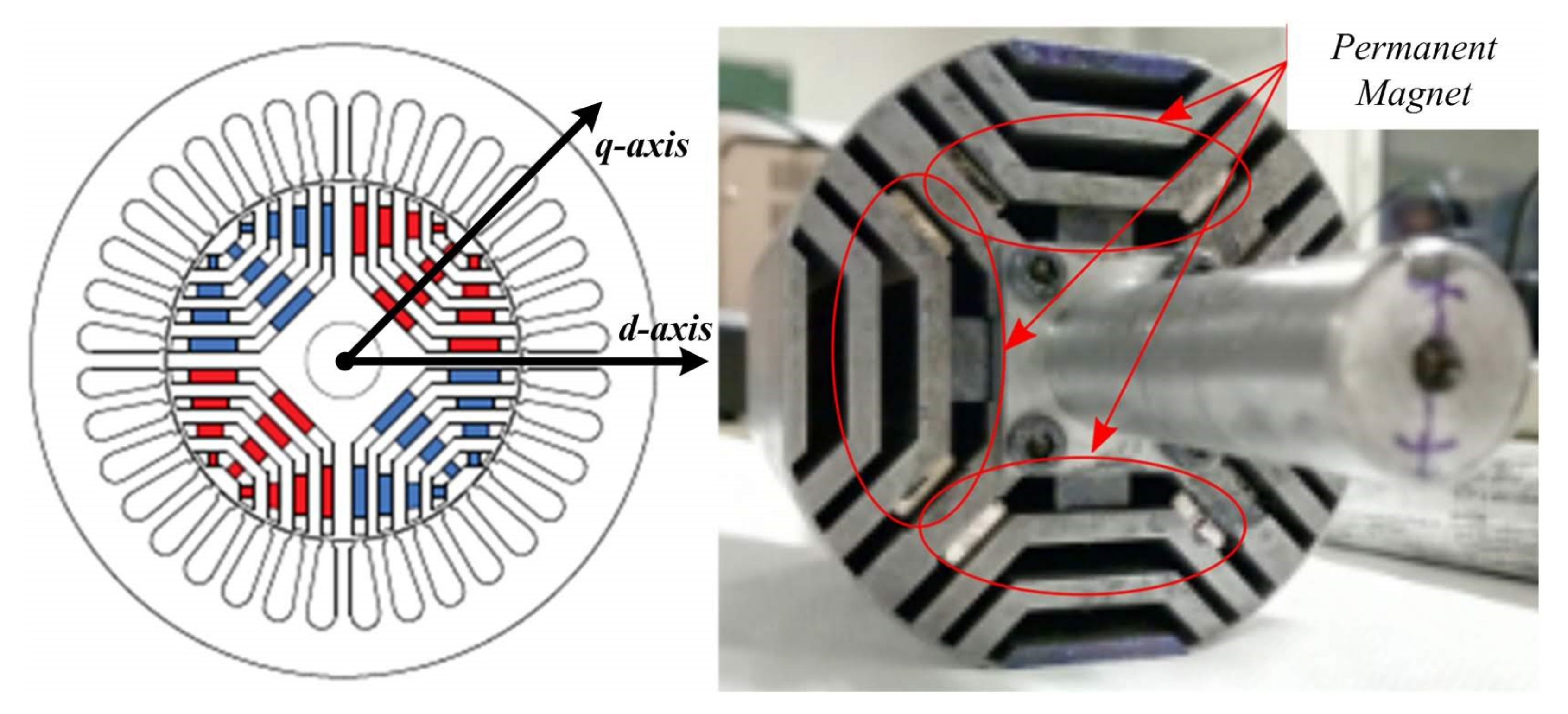
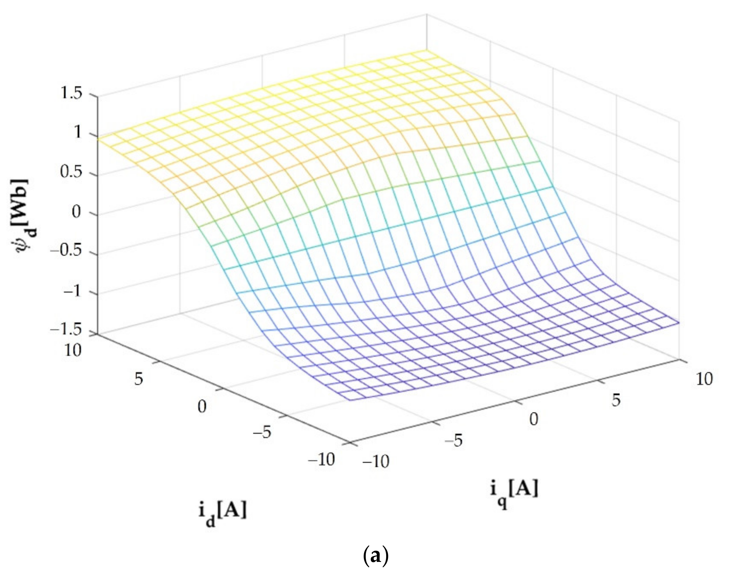
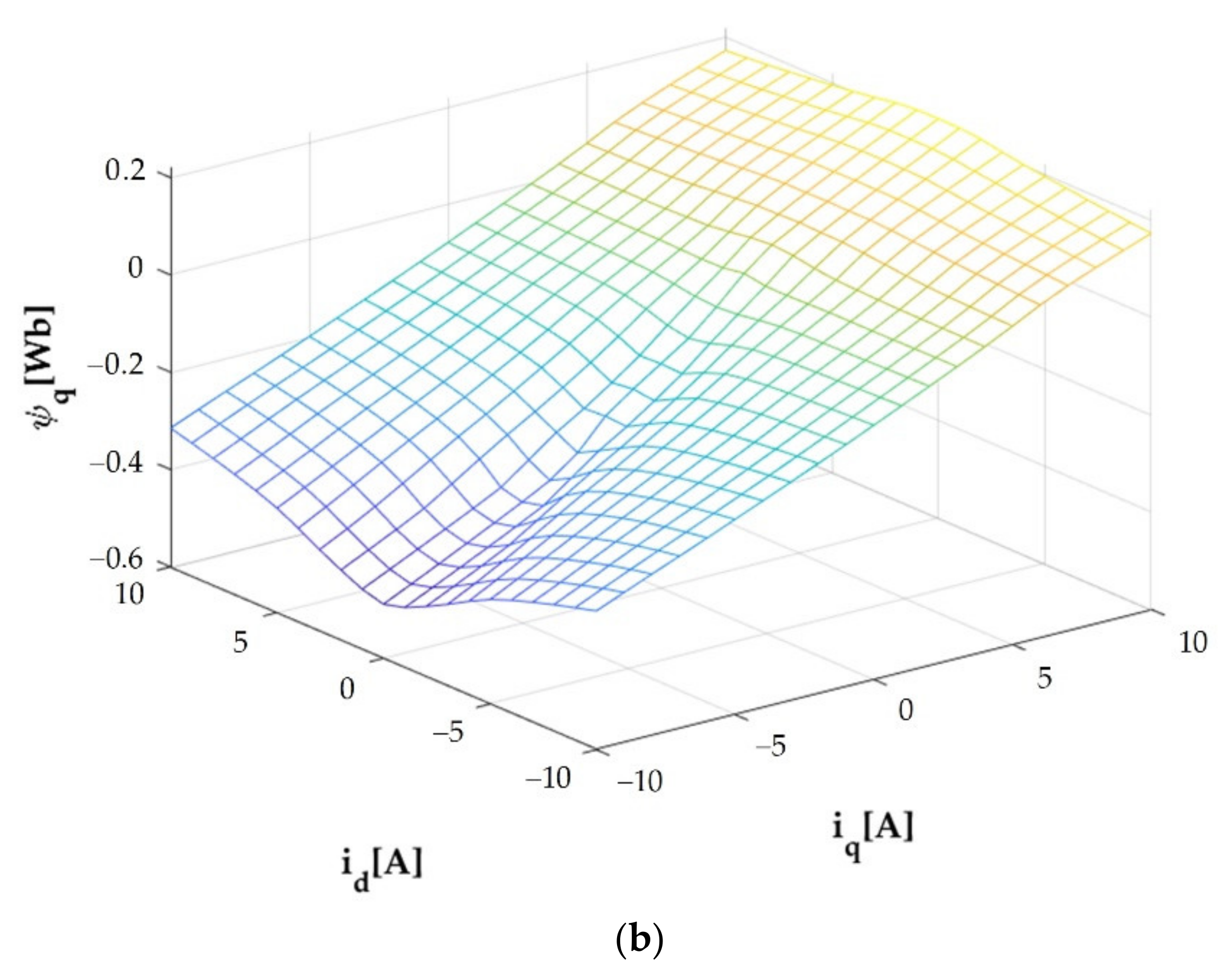
2. FEM-Based Magnetic Model

Given that the inductances Ld and Lq play major roles in the overload capacity, the field-weakening operation has been enhanced, and an accurate regulation has been determined to make their calculation easier. The inductances in the d–q axis have been computed considering a nonlinear case where the saturation of the stator teeth and rotor ribs have been taken into account. Due to the effect of the internal temperature, the inductances can be saturated as emphasized in [10]. Hence, the saturation effects of the inductances Ld and Lq can be computed relying on the link between the flux linkage change and the small rise in the current of the d–q axis, as provided by the Equations (1)–(3) [18,19]. Furthermore, the cross-coupling effects due to saturation have been investigated as well for the PMa-SynRM. The parameters have been assessed in the d–q axis. The operating constraints of the current supply have been reproduced, and the flux linkages have been assessed by incorporating the magnetic vector potential. The d-q flux linkages linked to the d- and q-axes currents are illustrated in Figure 2. The d- and q-flux linkages related to based on FEM analysis are represented in Figure 2. Figure 2a depicts the lookup table of d-axis flux linkage Ψd(id,iq) (LUT1); while Figure 2b exhibits the lookup q-axis flux linkage Ψq(id,iq) (LUT2). In addition, Table 1 shows the given flux linkages of the PMs and d–q axes inductances of the control network design.
L d = Ψ d ( i d , i q ) i d = Δ Ψ d ( i d , i q ) Δ i d i q = constant
L q = Ψ q ( i d , i q ) i q = Δ Ψ q ( i d , i q ) Δ i q i d = constant
L dq = Ψ d ( i d , i q ) i q = Δ Ψ d ( i d , i q ) Δ i q i d = constant

3. A Shot Briefly Differential Flatness Control and Control Law

3.1. Differential Flatness Briefly
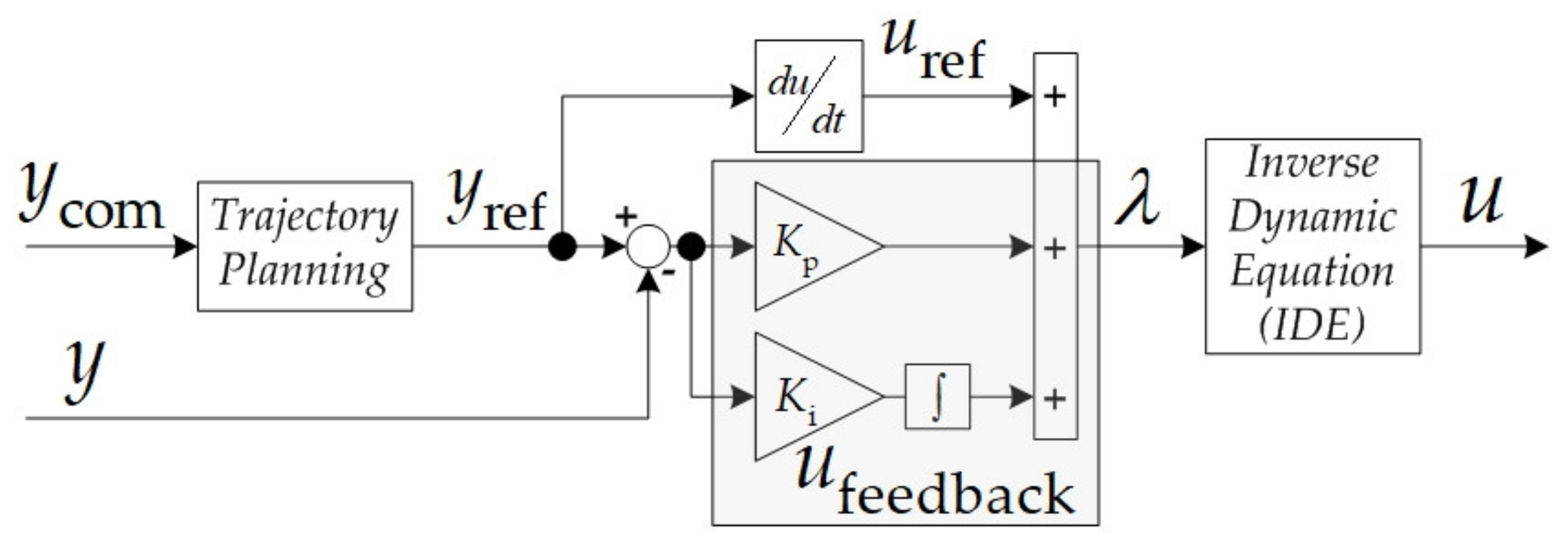
The differential flatness-based control approach is crucial to control different types of systems [2,13,14]. A summary of differential flatness control theory is provided below. Considering a nonlinear system expressed by the following state-variable:
x ˙ = f ( x , u ) .
The system (4) is said to be “differentially flat” if a set of flat output equal to the number of inputs can be found. More precisely, the control output variable must be written as the function of the flat output and their derivatives as follow:
x = ϕ ( y , y ˙ , , y ( β ) ) ,
u = ψ ( y , y ˙ , , y ( β + 1 ) ) ,
where β is the finite number of derivatives.

3.2. Control Law

The control law’s block diagram is provided in Figure 3. The trajectory planning, the feedback control (relying on two controller gains Ki and Kp), the controller output λ, and the inverse dynamic equations are detailed below.
As shown in Figure 3, a controller output, λ can be defined as follow:
λ = u ref + u feedback ( ε ) ,
with
u r e f = ψ ( y ref , y ˙ ref , y ¨ ref , , y ref ( β + 1 ) ) ,
ε = y r e f y .
As will be seen later, thank to “Inverse Dynamic Equation” (IDE), we will obtain.
y ˙ = λ .
According to the control law’s block diagram, combining (6)–(8) yields.
y ˙ = y ˙ r e f + K p ε + K i ε d t = 0 .
Taking time derivative (10) obtains.
y ¨ r e f + K p ε ˙ + K i ε = 0 .
By comparing to the standard second-order equation, parameters Kp and Ki can define as follow:
q ¨ ( s ) + 2 ζ ω n q ˙ ( s ) + ω n 2 q ( s ) = 0 ,
Consequently, the controller gains define as follow:
K p = 2 ζ ω n K i = ω n 2

4. PMa-SynRM Modeling and Development of the Proposed Control Scheme

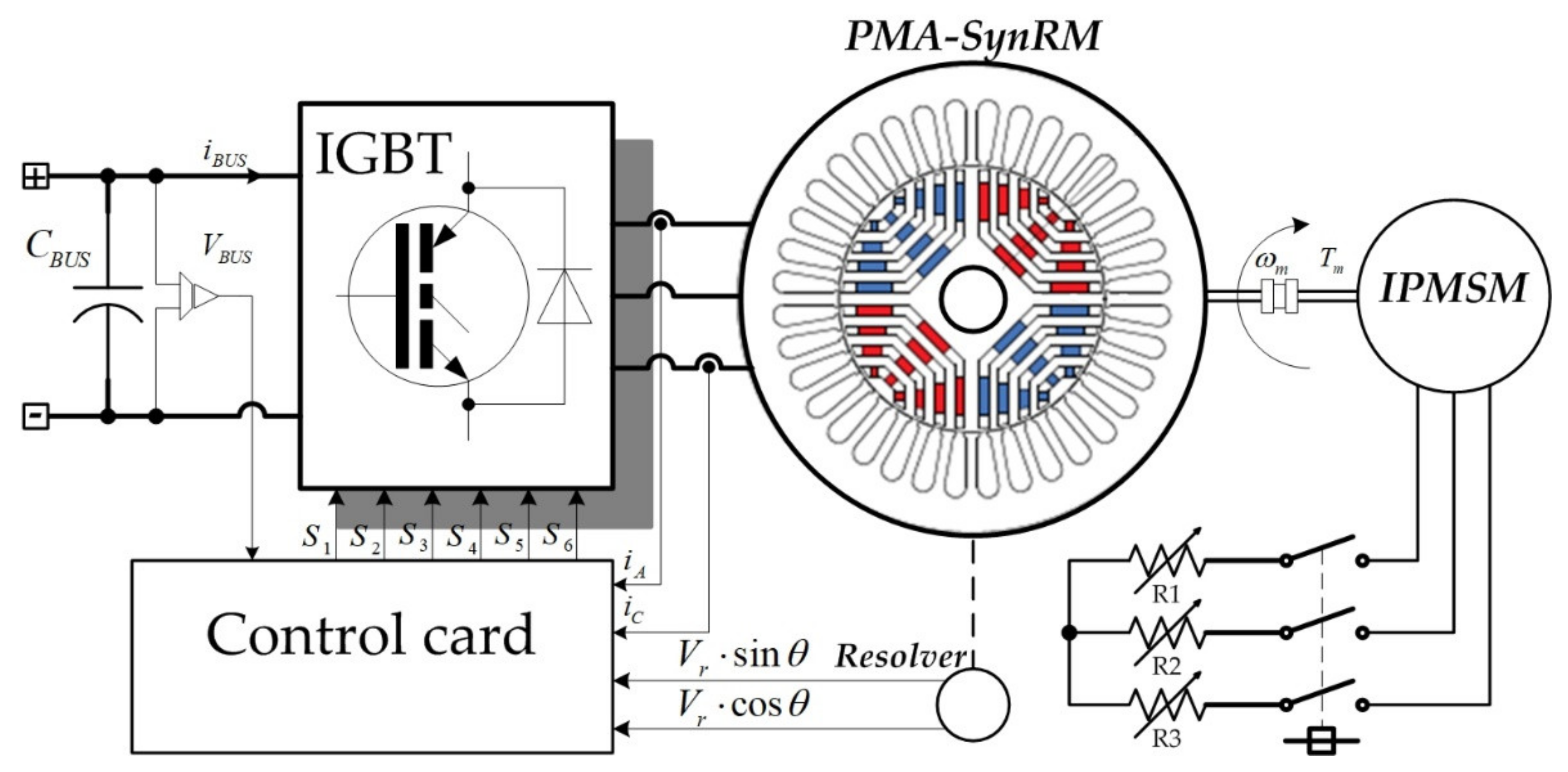
4.1. Mathematic Model of PMa-SynRM/Inverter

The inverter shown in Figure 4 provides a symmetric sinusoidal three-phase AC voltage source for supplying to PMa-SynRM. In Figure 4, VBUS, iBUS, and iA, iC are respectively the input DC grid voltage, the inverter current, and the load motor phase current. According to Figure 2a,b, The electrical modeling equations of PMa-SynRM are discussed by the nonlinear case. In Figure 2, the flux linkage of direct and quadrature axes may be defined according to d- and q-axes current id and iq as in the following equations.
Ψ d = Ψ d ( i d , i q ) ,
Ψ q = Ψ q ( i d , i q ) .
By considering Equations (14) and (15) as well, as mentioned above, the rotating electrical modeling of PMa-SynRM is given by the following equations [10,17]:
v d = R s i d + d Ψ d ( i d , i q ) d t ω e Ψ q ( i d , i q ) ,
v q = R s i q + d Ψ q ( i d , i q ) d t + ω e Ψ d ( i d , i q ) ,
where
ω e = n p ω m ,
where v d is the d-axis voltage, v q is the q-axis voltage, ω e is the electrical angular frequency, n p is the number of pole pairs, and ω m is the mechanical angular frequency. The important electromagnetic torque of the machine composed of torque produced with the interactivity between the magnet and the reluctance torque is expressed as follows.
T e = n p Ψ d i q Ψ q i d .
The mechanical equation in the rotation moving is:
J d ω m d t = T e B f ω m T L ,
where J is the moment of inertia, B f is the viscosity, and T L is the load torque.

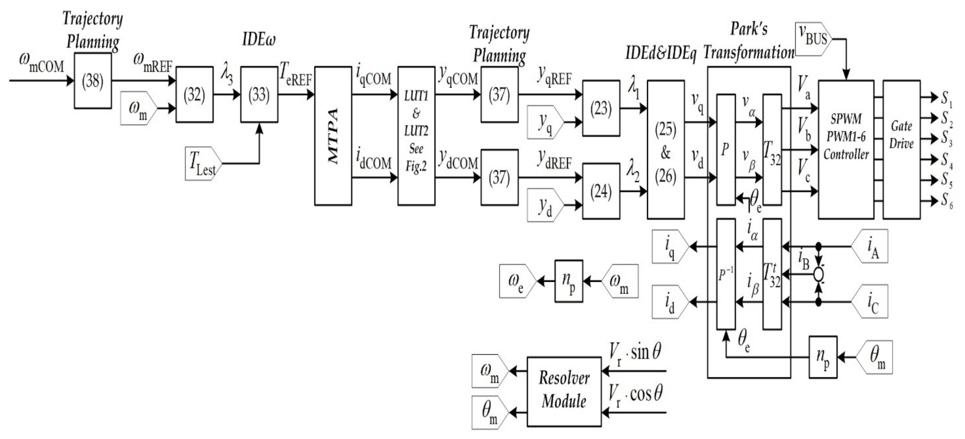
4.2. Differential Flatness Control of Current (or Torque) Loop Development

By referring to Equations (5), (16) and (17), the Ψd and Ψq are determined as the state variables (x). The vd and vq are control variables (u). The flat output (y) candidates are the measured parameters, which are id and iq. The systems can be seen as differentially flat if the control output variable must be noted according to the flat output, which are
v d = u 1 = R s y 1 ω e Ψ q y 1 , y 2 + Ψ d y 1 , y 2 y 1 y ˙ 1 + Ψ d y 1 , y 2 y 1 y ˙ 2 = ψ 1 y 1 , y 2 , y ˙ 1 , y ˙ 2 ,
v q = u 2 = R s y 2 + ω e Ψ d y 1 , y 2 + Ψ q y 1 , y 2 y 1 y ˙ 1 + Ψ q y 1 , y 2 y 2 y ˙ 2 = ψ 2 y 1 , y 2 , y ˙ 1 , y ˙ 2 .
The control scheme mentioned in Section 3.2 is applied to deal with some inevitable modeling errors and uncertainties. By referring to Equation (6), the control laws of current control can express as follow:
y ˙ 1 = Ψ ˙ d r e f + K p ε d + K i ε d d t ,
y ˙ 2 = Ψ ˙ q r e f + K p ε q + K i ε q d t .
Consequently, the output control variables yield as follow:
u 1 = v d = y ˙ 1 + I D E d ,
u 2 = v q = y ˙ 2 + I D E q ,
where the Inverse Dynamic Equations (IDEs) are
I D E d = R s i d + ω e Ψ q ,
I D E q = R s i q + ω e Ψ d .
The controller parameters are
K p d = K p q = 2 ζ 1 ω n 1 ,
and
K i d = K i q = ω n 1 2 ,
where ζ1 and ωn1 are respectively the desirated governing damping ratio and natural frequency.

4.3. Differential Flatness Control of Speed Control Loop Development

Figure 5 shows the proposed control diagram. The outer speed loop enables evaluating the torque reference value of the MPTA, which generates the current command for the inner current loop.
For the MTPA algorithm, it has been proposed in [20]. So, the Te is defined as a command variable u3, and the flat output y3 is ωm (or measured angular speed). The system is flat if the control variable is a function of flat output that is
u 3 = T e = J y ˙ 3 + B f y 3 + T L = ψ 3 y 3 , y ˙ 3 .
The control strategy of the speed control loop is
y ˙ 3 = ω ˙ r e f + K p ω ε ω + K i ω ε ω d t .
The control variable of the speed loop can be express as follow:
u 3 = J y ˙ 3 + J I D E ω ,
where the inverse dynamic equation of the speed control loop (IDEω) is
I D E ω = 1 J B f y 3 + T L .
The controller parameters are defined as the following equation.
K p ω = 2 ζ 2 ω n 2 ,
and
K i ω = ω n 2 2 ,
where ζ2 and ωn2 are, respectively, the desirated governing damping ratio and the natural frequency of the outer speed regulation loop.
Based on the current and speed control law development, the natural frequency setting of the designed controller is depicted in Figure 6. The switching frequency fs of the inverter shown in Figure 4 is equal to 16 kHz (ωs = 105 rad.s−1) and it is reported in Figure 6. According to Figure 5, the speed control loop must be faster than the current control loop given that the outer speed loop enables assessing the torque reference value, and consequently the current. Considering the Nyquist-Shannon Theorem, the natural frequency ωn1 must be chosen lower than a frequency equal to 102 rad.s−1 (namely two times lower than the switching frequency ωs). Therefore, the natural frequency ωn1 for the current control loop has been tuned at 2000 rad.s−1; while for the speed control loop, a natural frequency ωn2 has been set at 20 rad.s−1 (100 times lower than ωn1). Both values have been reported in Figure 6, allowing defining the stable region included between these two values; whereas the unstable region is outside the natural frequency ωn1. Regarding the tuning of the damping ratios ζ1 and ζ2, to guarantee underdamped transient behaviors with low overshoot and fast response, both parameters have been set at 0.7.
Note that the stability and response of the differential flatness-based control are easy to set compared to the traditional PI controller. By defining and selecting the governing damping and natural frequency [21,22], as shown in Figure 6, the controller parameters of current and speed loop control may be calculated by Equations (29), (30), (35) and (36).

4.4. Trajectory Planning

The trajectory planning enables restricting the derivative terms. The reference inputs have been defined by trajectory planning utilized by the second-order low-pass filter. The trajectory planning of the current control loops are
y 1 R E F ( s ) y 1 C O M ( s ) = y 2 R E F ( s ) y 2 C O M ( s ) = 1 / s ω n 3 2 + 2 ζ 3 ω n 3 + 1 .
In the speed control loop, the trajectory planning has been determined by the following equation.
y 3 R E F ( s ) y 3 C O M ( s ) = 1 / s ω n 4 2 + 2 ζ 4 ω n 4 + 1 ,
where ζ 3 , ω 3 , ζ 4 , and ω 4 are the governing damping and natural frequencies of the second-order low-pass filters, respectively.

5. Simulation and Experimental Validation

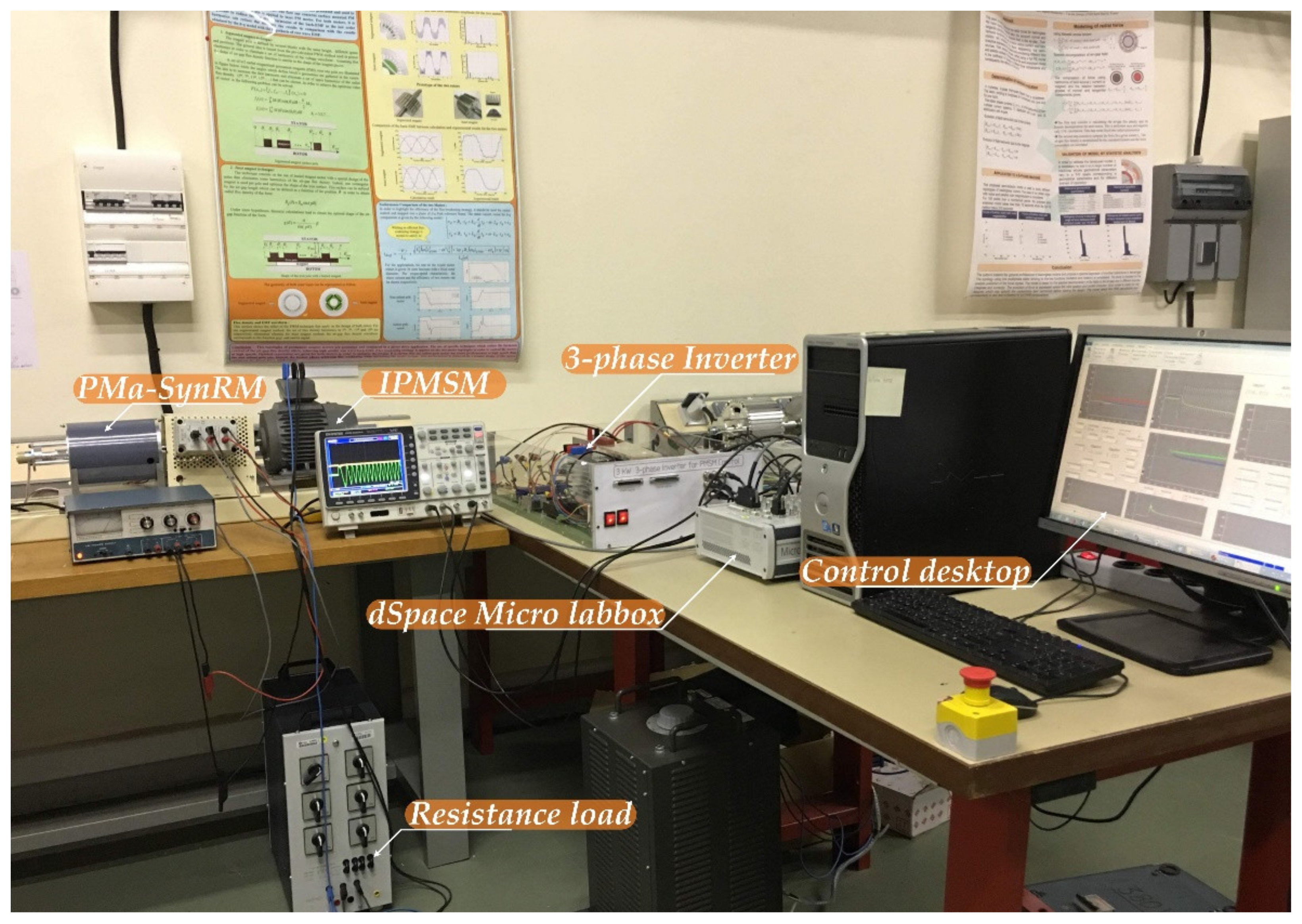
5.1. Experimental Setup

A small-scale test bench 1-KW relying on the PMa-SynRM has been conceived in the laboratory, as shown in Figure 7. Table 2 sums up the principal parameters of the studied machine. Table 3 outlines the controller parameters. The motor is supplied by a 3-kW 3-phase inverter (DC/AC) operating at a switching frequency of 16 kHz. Besides, the input DC grid voltage of the inverter is fed by a 3-phase variable power supply combined with a 3-phase diode rectifier. The PMa-SynRM is mechanically coupled with an IPMSM (interior permanent magnet synchronous motor) feeding a resistive load (see Figure 4 and Figure 7). Regarding the measurements both for the speed and rotor angle, they have been acquired by a resolver placed on the rotor shaft. The developed control scheme (see Figure 5) relying on the differential flatness controller has been modeled in the Matlab/Simulink software, and then it has been incorporated in the dSPACE 1202 MicroLabBox real-time interface to generate the gate control signals applied to the VSI.

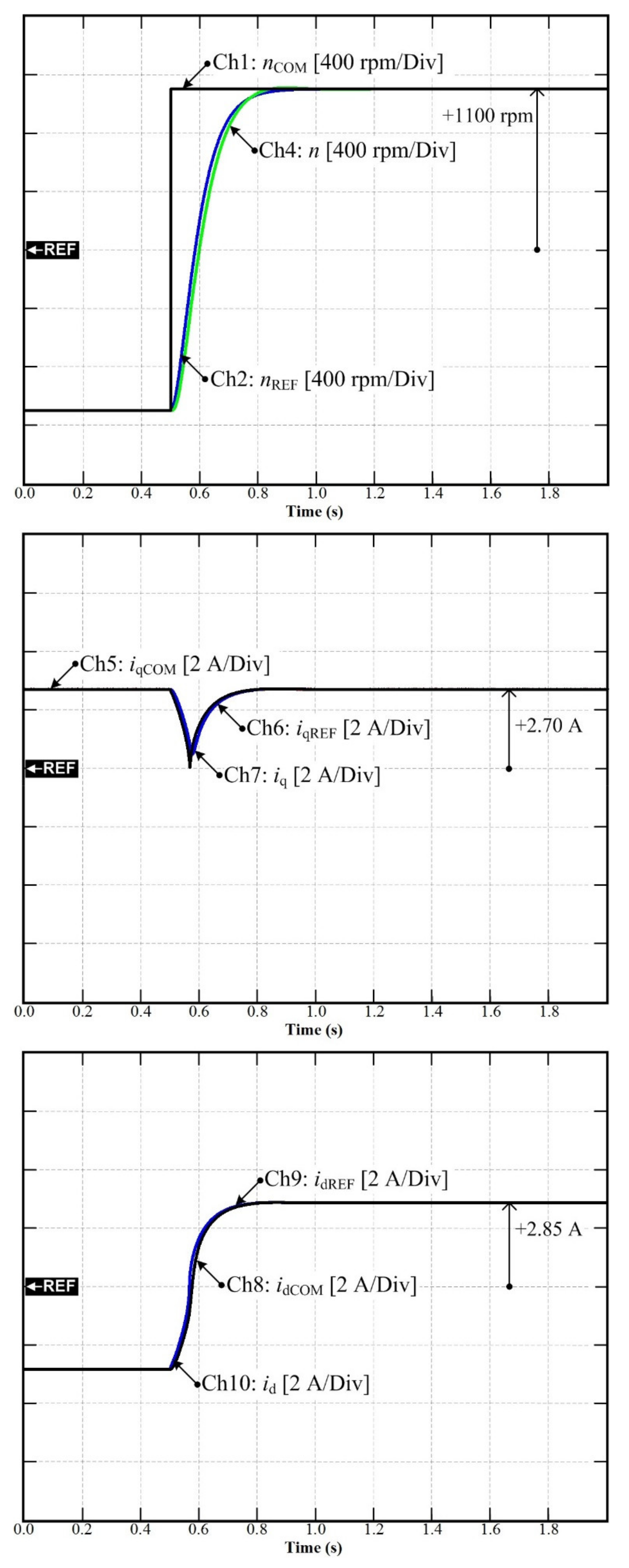
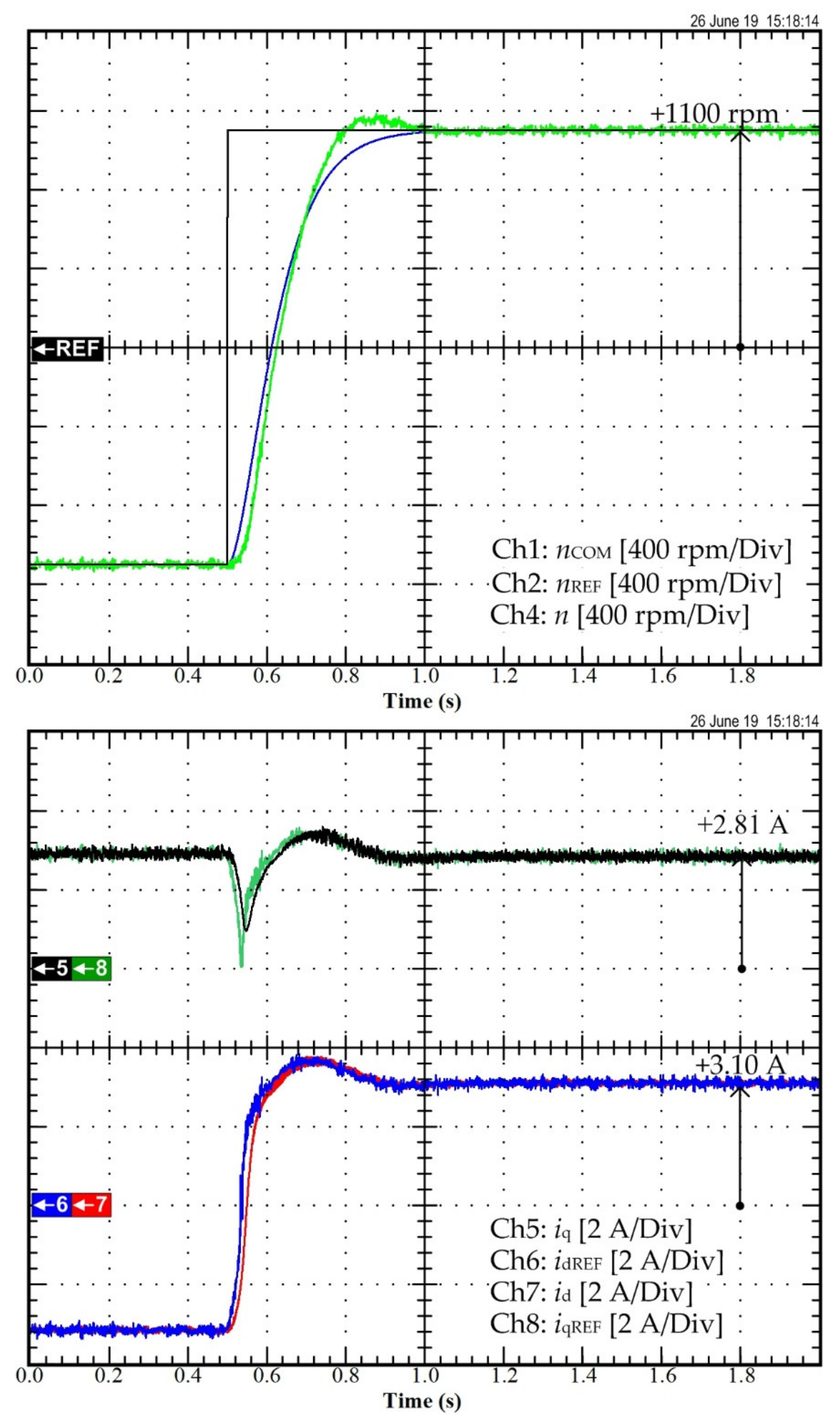
5.2. Simulation and Test-Bench Results of the Speed Reversal Employing the Differential Flatness Controller

For the first scenario, Figure 8 reports the obtained simulation results; whereas, Figure 9 exhibits the performed experimental tests to assess the dynamic performance of the designed controller when forcing the motor to reverse direction. In Figure 8, Ch1–10 are the command signal of the speed nCOM, the reference signal of the speed nREF, the measured speed n, the command of q-axis current iqCOM, the reference of q-axis current iqREF, the q-axis current iq, the command of d-axis current idCOM, the reference of d-axis current idREF, and the d-axis current id, respectively. In comparison, in Figure 9, Ch1–8 are the speed command nCOM, the speed reference nREF, the measured speed n, the current iq, the current reference idREF, the current id, and the current reference iqREF, respectively. Firstly, the PMa-SynRM model has been tested by using Matlab/Simulink to support that the elaborated control system is appropriately conceived. Simulations and experimental tests have demonstrated that both simulation and experimental results are similar. Thus, the PMa-SynRM model is fit, and the controller parameters are suitably designed by choosing desired parameters. The experimental results indicate that the PMa-SynRM behaves in a good way when operating under the regenerative mode up to the speed the reference gets positive. Furthermore, it can be emphasized that the measured speed through the resolver enables tracking adequately the speed reference value. Afterward, the operation of the PMa-SynRM is shifted to the motoring mode up to the rotor speed comes to the speed command. The d-and q-axes currents reveal an appropriate behavior without surpassing the imposed limits. The dominant parameters of the PMa-SynRM enable being ensured, and the elaborated control offers worthwhile dynamic performance.

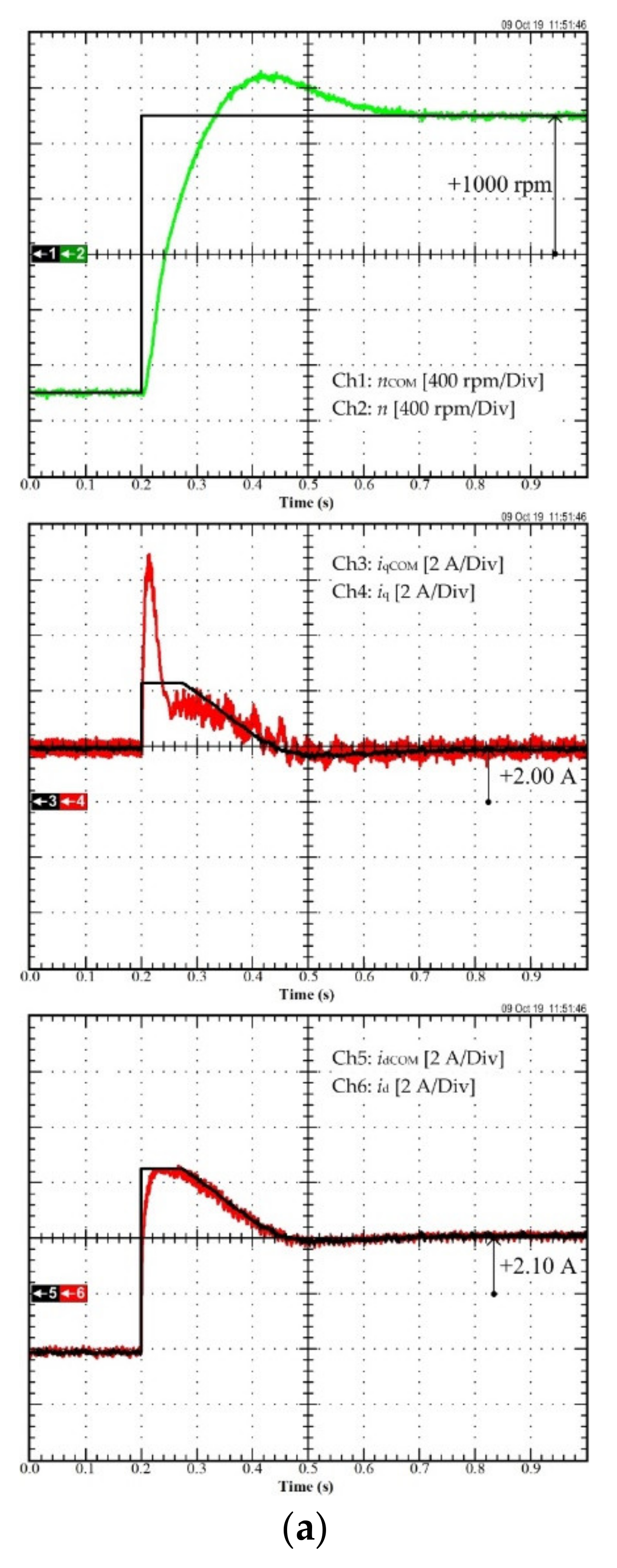
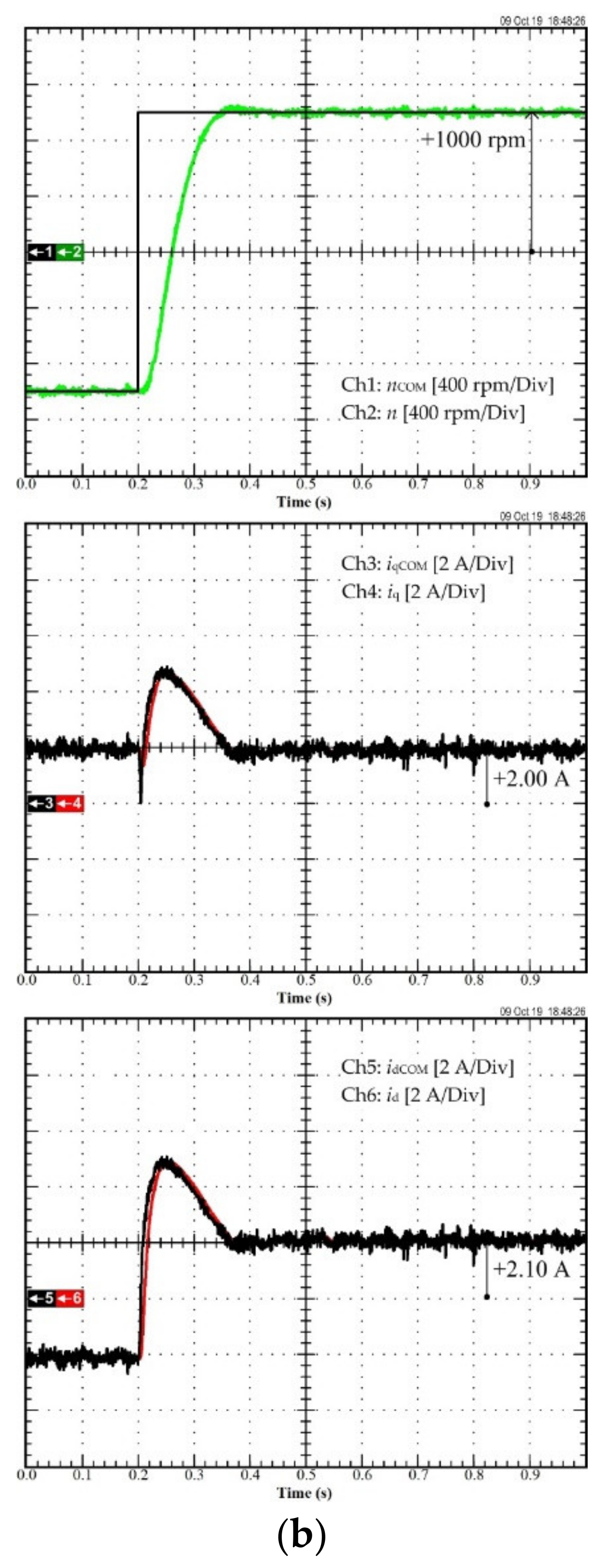
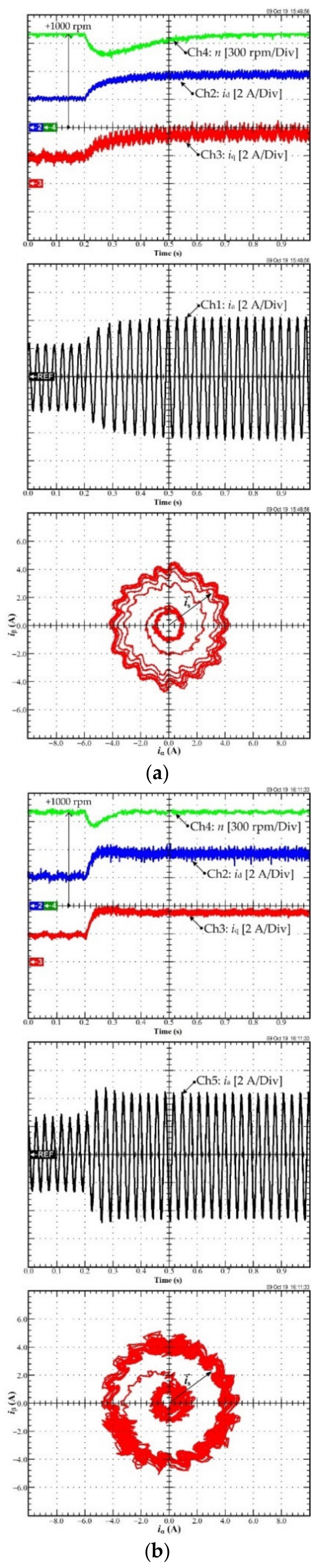
5.3. Experimental Results of the Comparison between the Conventional PI Control and Differential Flatness Control

For the second scenario, the performance of the system when the torque/current loop employs traditional PI control and differential flatness is compared to assess the benefits of the elaborated control scheme. Figure 10a represents the experimental results of the conventional PI control, and Figure 10b illustrates the experimental results of differential flatness control. In Figure 10a, Ch1 is the current idCOM, Ch3 is the measured current id, Ch4 is the measured current iq, and Ch5 is the measured speed n. In Figure 10b, Ch1 is the current idCOM, Ch3 is the measured current id, Ch4 is the measured current iq, and Ch5 is the measured speed n. As shown in Figure 10a,b, in a transitory operation, the id of PI control exhibits a small overshoot, compared to the differential flatness controller, and the iq of the PI control shows oscillations.
Although the PI controller has used decoupling and back-emf compensation, it demonstrates that the proposed nonlinear controller has a better transient current performance than the traditional linear controller. Furthermore, the speed response (Ch5 of Figure 10a) of the linear cascaded PI controller includes fluctuations, unlike the proposed nonlinear controller (Ch5 of Figure 10b).
For the third scenario, Figure 11a confirms the experimental results of the conventional PI controller, and Figure 11b indicates the experimental validation results of the differential flatness controller when the motor is forced to reverse direction from −1000 rpm to 1000 rpm. In Figure 11a, Ch1 is the speed command nCOM, Ch2 is the speed n, Ch3 is the current command iqCOM, Ch4 is the measured current iq, Ch5 is the current command idCOM, and Ch6 is the measured current id. In Figure 11b, Ch1 is the speed command nCOM, and Ch2 is the acquired speed n, Ch3 is the current command iqCOM, Ch4 is the measured current iq, Ch5 is the current command idCOM, and Ch6 is the measured current id. On one hand, as demonstrated in Figure 11a, during a transient process, the acquired speed n of the PI controller shows an overshoot, and the settling time is approximately 0.45 s. On the other hand, the differential flatness controller (Figure 11b), approximate time is around 0.15 s, as well as the measured iq of the PI controller, which fluctuates sharply (Ch4 of Figure 11a) in a transient process. The experimental results reflect that differential flatness has a better dynamic speed performance than the traditional PI controller.
For the fourth scenario, Figure 12a shows the test-bench results of the conventional PI controller; while, Figure 12b depicts the preliminary results of the differential flatness control when suddenly adding an external torque disturbance. In Figure 12a, Ch2 is the measured d-axis current id, Ch3 is the measured q-axis current iq, Ch4 is the measured speed n, Ch5 is the measured phase-A current ia, and the trajectories of the transient stator current. In Figure 12b, Ch2 is the measured d-axis current id, Ch3 is the measured q-axis current iq, Ch4 is the measured speed n, Ch5 is the phase-A current ia, and the path of the transient stator current. The experimental results are shown in Figure 12b, validating that differential flatness speed oscillation is roughly 113 rpm; whereas that for the PI controller is 221 rpm. The recuperation time of speed with the elaborated controller is also shorter than that with conventional PI control. These results corroborate that differential flatness control has better dynamic performance both for the torque/current and speed loop control and the external rejection ability.

6. Conclusions

To cope with the control issues met in a permanent magnet-assisted synchronous reluctance motor (PMa-SynRM), various control approaches have been previously investigated. Nonetheless, the achievement of high performance is still a challenging barrier due to the nonlinear characteristics and parameter uncertainty conditions of this motor. In this work, a differential flatness control law has been elaborated and designed to control both current/torque and the speed of the PMa-SynRM. Furthermore, an intelligent proportional-integral (iPI) has been combined with the nonlinear differential flatness controller to face unavoidable modeling errors and uncertainties for the torque and speed of the motor. This model-based approach requires an accurate model. In case the model is not perfectly known, the estimation of the unknown part is necessary to achieve the expected high performance. Through simulations and experimental tests performed on a small-scale test bench 1-KW including the PMa-SynRM, the dynamic performances of the system have been validated; while demonstrating the performance superiority of the differential flatness controller over the conventional PI controller from the overshoot and oscillation point of view. Furthermore, the results reflect that the dynamic recovery time response is faster using intelligent PI control than the field-oriented control (FOC) based on PI controller with approximately 0.15 s.
In the future work, another control approach will be tentatively applied to the control of PMa-SynRM. This approach, called the model-free control, does not require an accurate model. Indeed, only very limited knowledge of the controlled system is enough to regenerate the control action. Advantages and drawbacks of this controller will be discussed and its performance will be compared to the flatness-based controller in the next work.

Author Contributions

Conceptualization, B.N.-M. and N.T.; methodology, S.S., N.P., D.G. and P.T.; validation, S.S., N.P., D.G. and P.T.; formal analysis, N.B.; writing—original draft preparation, P.T.; writing—review and editing, S.S., D.G. and N.B.; visualization, N.B.; supervision, B.N.-M. and N.T. All authors have read and agreed to the published version of the manuscript.

Funding

This work was partially supported by the International Research Partnerships: Electrical Engineering Thai-French Research Center (EE-TFRC) between Université de Lorraine (UL) and King Mongkut’s University of Technology North Bangkok (KMUTNB) and Framework Agreement between the University of Pitesti and King Mongkut’s University of Technology North Bangkok through the Research Program Cooperation under Grant KMUTNB–61–GOV–01–67. Besides, this work was supported partly by the French PIA project «Lorraine Université d’Excellence», reference ANR-15-IDEX-04-LUE.

Institutional Review Board Statement

Not applicable.

Informed Consent Statement

Not applicable.

Data Availability Statement

The data presented in this study are available on request from the corresponding authors. The data are not publicly available due to their current utilization for future works involving the authors of this paper.

Acknowledgments

The authors would like to express their gratitude to the GREEN laboratory at the University of Lorraine and King Mongkut’s University of Technology North Bangkok (KMUTNB) for their constant support in boosting collaborations between France and Thailand.

Conflicts of Interest

The authors declare no conflict of interest.

References

  1. Grasso, E.; Palmieri, M.; Corti, F.; Nienhaus, M.; Cupertino, F.; Grasso, F. Detection of stator turns short-circuit during sensorless operation by means of the Direct Flux Control technique. In Proceedings of the 2020 AEIT International Annual Conference (AEIT), Catania, Italy, 23–25 September 2020. [Google Scholar]
  2. Lim, C.; Rahim, N.; Hew, W.; Levi, E. Model Predictive Control of a Two-Motor Drive with Five-Leg-Inverter Supply. IEEE Trans. Ind. Electron. 2013, 60, 54–65. [Google Scholar] [CrossRef]
  3. Wang, L.; Jatskevich, J.; Dommel, H. Re-examination of Synchronous Machine Modeling Techniques for Electromagnetic Transient Simulations. IEEE Trans. Power Syst. 2007, 22, 1221–1230. [Google Scholar] [CrossRef]
  4. Fan, Y.; Zhang, Q.; Wang, W.; Zhou, X. Speed Regulation System of a Flux-Modulated Permanent-Magnet In-Wheel Motor Based on Sliding Mode Control and Adaptive Notch Filter. IEEE Trans. Energy Convers. 2018, 33, 2183–2190. [Google Scholar] [CrossRef]
  5. Erazo, D.; Wallscheid, O.; Bocker, J. Improved Fusion of Permanent Magnet Temperature Estimation Techniques for Synchronous Motors Using a Kalman Filter. IEEE Trans. Ind. Electron. 2020, 67, 1708–1717. [Google Scholar] [CrossRef]
  6. Morimoto, S.; Ooi, S.; Inoue, Y.; Sanada, M. Experimental Evaluation of a Rare-Earth-Free PMASynRM With Ferrite Magnets for Automotive Applications. IEEE Trans. Ind. Electron. 2014, 61, 5749–5756. [Google Scholar] [CrossRef]
  7. Morimoto, S.; Sanada, M.; Takeda, Y. Performance of PM-assisted synchronous reluctance motor for high-efficiency and wide constant-power operation. IEEE Trans. Ind. Appl. 2001, 37, 1234–1240. [Google Scholar] [CrossRef]
  8. Park, G.; Kim, J.; Son, B.; Jung, S. Optimal Design of PMa-synRM for an Electric Propulsion System Considering Wide Operation Range and Demagnetization. IEEE Trans. Appl. Supercond. 2018, 28, 1–4. [Google Scholar] [CrossRef]
  9. Boldea, I.; Tutelea, L.; Pitic, C. PM-Assisted Reluctance Synchronous Motor/Generator (PM-RSM) for Mild Hybrid Vehicles: Electromagnetic Design. IEEE Trans. Ind. Appl. 2004, 40, 492–498. [Google Scholar] [CrossRef]
  10. Niazi, P.; Toliyat, H.; Goodarzi, A. Robust Maximum Torque per Ampere (MTPA) Control of PM-Assisted SynRM for Traction Applications. IEEE Trans. Veh. Technol. 2007, 56, 1538–1545. [Google Scholar] [CrossRef]
  11. Trancho, E.; Ibarra, E.; Arias, A.; Kortabarria, I.; Jurgens, J.; Marengo, L.; Fricasse, A.; Gragger, J. PM-Assisted Synchronous Reluctance Machine Flux Weakening Control for EV and HEV Applications. IEEE Trans. Ind. Electron. 2018, 65, 2986–2995. [Google Scholar] [CrossRef] [Green Version]
  12. Thounthong, P.; Sikkabut, S.; Poonnoy, N.; Mungporn, P.; Yodwong, B.; Kumam, P.; Bizon, N.; Nahid-Mobarakeh, B.; Pierfederici, S. Nonlinear Differential Flatness-Based Speed/Torque Control With State-Observers of Permanent Magnet Synchronous Motor Drives. IEEE Trans. Ind. Appl. 2018, 54, 2874–2884. [Google Scholar] [CrossRef]
  13. Thounthong, P.; Pierfederici, S.; Davat, B. Analysis of Differential Flatness-Based Control for a Fuel Cell Hybrid Power Source. IEEE Trans. Energy Convers. 2010, 25, 909–920. [Google Scholar] [CrossRef] [Green Version]
  14. Variani, M.; Tomsovic, K. Two-Level Control of Doubly Fed Induction Generator Using Flatness-Based Approach. IEEE Trans. Power Syst. 2016, 31, 518–525. [Google Scholar] [CrossRef]
  15. Menhour, L.; d’Andrea-Novel, B.; Fliess, M.; Gruyer, D.; Mounier, H. An Efficient Model-Free Setting for Longitudinal and Lateral Vehicle Control: Validation through the Interconnected Pro-SiVIC/RTMaps Prototyping Platform. IEEE Trans. Intell. Transp. Syst. 2018, 19, 461–475. [Google Scholar] [CrossRef] [Green Version]
  16. Fliess, M.; Join, C. Model-free control. Int. J. Control 2013, 86, 2228–2252. [Google Scholar] [CrossRef] [Green Version]
  17. Kerdsup, B.; Takorabet, N.; Nahidmobarakeh, B. Design of Permanent Magnet-Assisted Synchronous Reluctance Motors with Maximum Efficiency-Power Factor and Torque per Cost. In Proceedings of the 2018 XIII International Conference on Electrical Machines (ICEM), Alexandroupoli, Greece, 3–6 September 2018. [Google Scholar]
  18. Ding, T. Study and Optimization of Line-Start Permanent Magnet Motors. Ph.D. Dissertation, Université Henri Poincaré, Nancy, France, 2011. [Google Scholar]
  19. Chen, X.; Wang, J.; Sen, B.; Lazari, P.; Sun, T. A High-Fidelity and Computationally Efficient Model for Interior Permanent-Magnet Machines Considering the Magnetic Saturation, Spatial Harmonics, and Iron Loss Effect. IEEE Trans. Ind. Electron. 2015, 62, 4044–4055. [Google Scholar] [CrossRef]
  20. Sriprang, S.; Nahid-Mobarakeh, B.; Takorabet, N.; Pierfederici, S.; Kumam, P.; Bizon, N.; Taghavi, N.; Vahedi, A.; Mungporn, P.; Thounthong, P. Design and control of permanent magnet assisted synchronous reluctance motor with copper loss minimization using MTPA. J. Electr. Eng. 2020, 71, 11–19. [Google Scholar] [CrossRef]
  21. Sriprang, S.; Nahid-Mobarakeh, B.; Takorabet, N.; Pierfederici, S.; Bizon, N.; Kuman, P.; Thounthong, P. Permanent Magnet Synchronous Motor Dynamic Modeling with State Observer-based Parameter Estimation for AC Servomotor Drive Application. Appl. Sci. Eng. Prog. 2019, 12. [Google Scholar] [CrossRef]
  22. Veeser, F.; Braun, T.; Kiltz, L.; Reuter, J. Nonlinear Modelling, Flatness-Based Current Control, and Torque Ripple Compensation for Interior Permanent Magnet Synchronous Machines. Energies 2021, 14, 1590. [Google Scholar] [CrossRef]
Figure 1. The rotor’s structure of the proposed PMa-SynRM.
Sustainability 13 09502 g001
Figure 2. The flux linkages Ψd and Ψq in the function of id and iq. (a) Ψd(id,iq). (b) Ψq(id,iq).
Sustainability 13 09502 g002aSustainability 13 09502 g002b
Figure 3. Control law’s block diagram.
Sustainability 13 09502 g003
Figure 4. A three-phase inverter to control the PMa-SynRM prototype.
Sustainability 13 09502 g004
Figure 5. Schematic drawing of the designed control scheme.
Sustainability 13 09502 g005
Figure 6. The natural frequency setting of the designed controller.
Sustainability 13 09502 g006
Figure 7. The experimental setup.
Sustainability 13 09502 g007
Figure 8. Simulation results: motor speed reversal.
Sustainability 13 09502 g008
Figure 9. Experimental results: motor speed reversal.
Sustainability 13 09502 g009
Figure 10. Experimental results: (a) the traditional PI control, (b) the differential flatness control.
Sustainability 13 09502 g010
Figure 11. Experimental results: (a) the traditional PI control, (b) the differential flatness control.
Sustainability 13 09502 g011aSustainability 13 09502 g011b
Figure 12. Experimental results: (a) the traditional PI control (b) the differential flatness control.
Sustainability 13 09502 g012
Table 1. Properties of the PMa-SynRM parameters relying on FEM analysis.
SymbolQuantityValue
ΨmPermanent magnet flux0.138 Wb
LdNormal d-axis self-inductance288 mH
LqNormal q-axis self-inductance38 mH
LdqMutual inductance4 mH
Table 2. Specification and parameters of the motor/inverter.
SymbolQuantityValue
PratedRated power1 kW
nratedRated speed1350 rpm
TratedRated torque7.07 Nm
npNumber of pole pairs2
PF.Power factor0.80
RsResistance (motor + inverter)3.2 Ω
LdNominal d-axis Inductance288 mH
LqNominal q-axis Inductance38 mH
JEquivalent inertia0.017 kg m2
BfViscous friction coefficient0.008 Nm s/rad
ΨmPMs flux linkage0.138 Wb
fsSwitching frequency16 kHz
VdcDC bus voltage400 V
Table 3. Current/torque and speed regulation parameters.
SymbolQuantityValue
ζ 1 Governing Damping ratio 10.7 pu.
ω n 1 Natural frequency 12000 Rad.s−1
ζ 2 Governing Damping ratio 20.7 pu.
ω n 2 Natural frequency 220 Rad.s−1
ζ 3 Governing Damping ratio 31 pu.
ω n 3 Natural frequency 3200 Rad.s−1
ζ 4 Governing Damping ratio 41 pu.
ω n 4 Natural frequency 420 Rad.s−1
TemaxMaximum Torque+10 Nm
TeminMinimum Torque−10 Nm
Publisher’s Note: MDPI stays neutral with regard to jurisdictional claims in published maps and institutional affiliations.

