
Innovative Design Concept of Cooling Water Tanks/Basins in Geothermal Power Plants Using Ultra-High-Performance Fiber-Reinforced Concrete with Enhanced Durability


 ,
,
Abstract
:1. Introduction
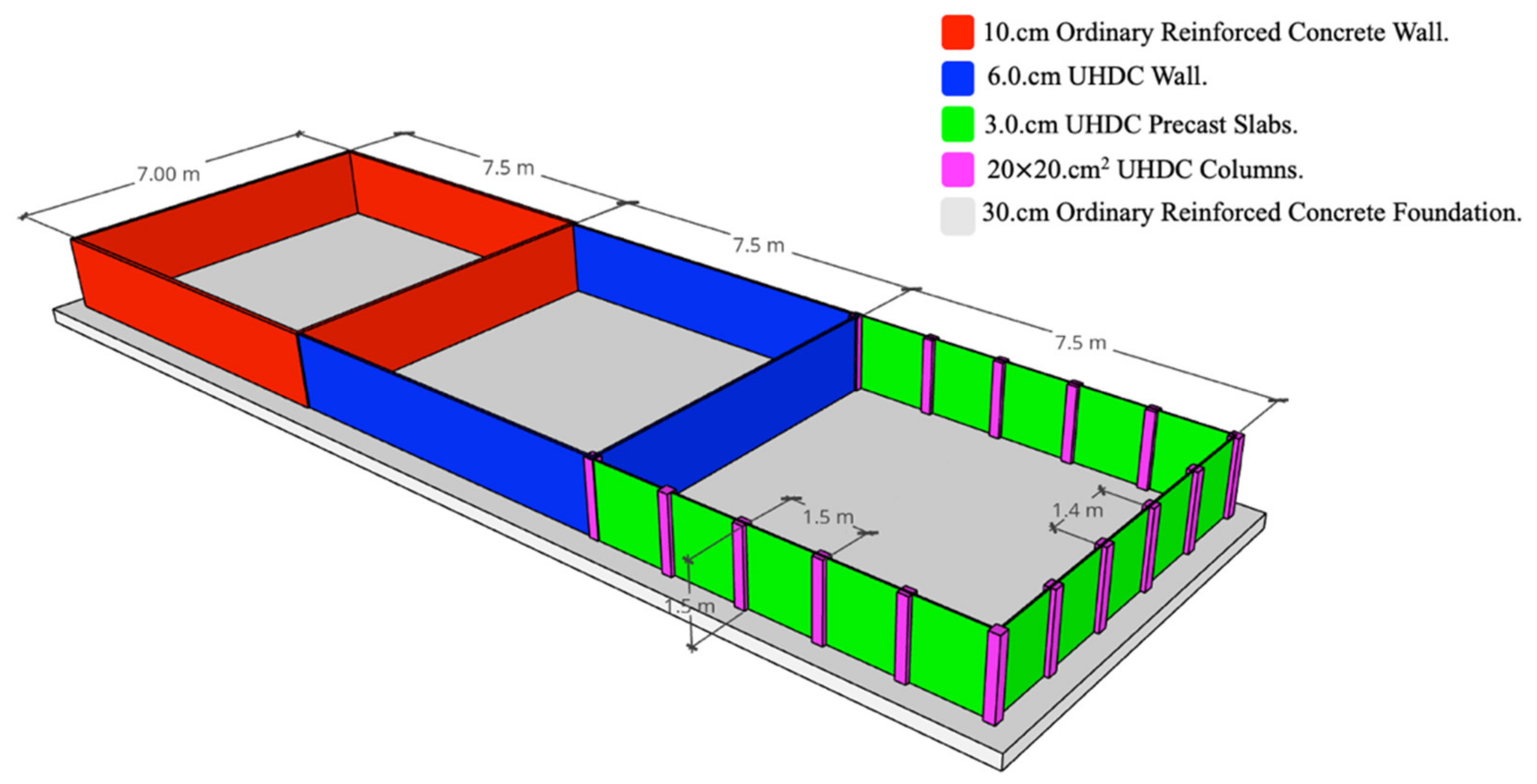
- (a)
- A 100 mm-thick cast-in-place ordinary reinforced concrete wall.
- (b)
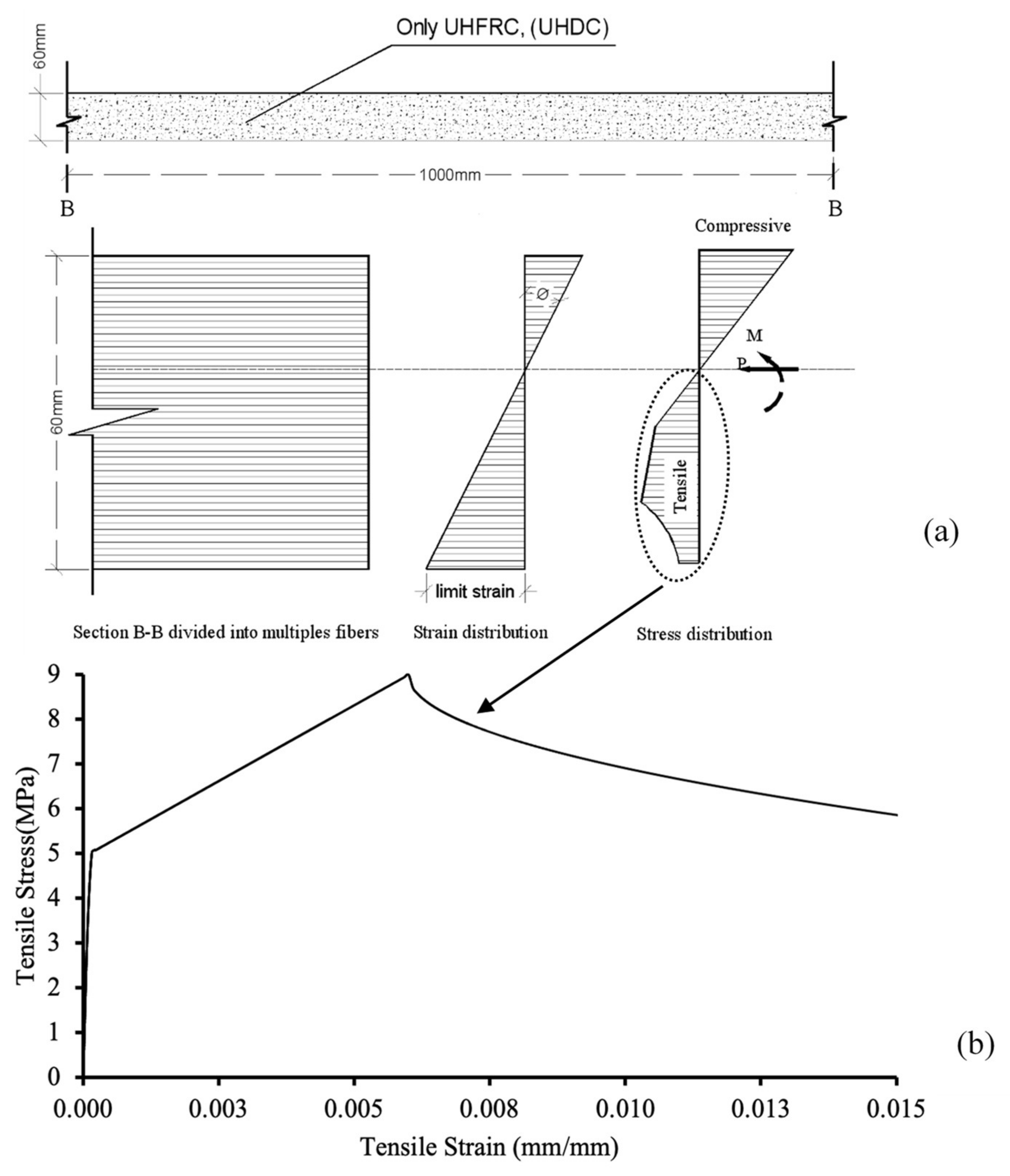
- A 60 mm-thick cast-in-place UHPC wall.
- (c)
- A solution consisting of 30 mm-thin precast UHPC slabs “supported” by 200 × 200 mm2 cast-in-place UHPC columns/buttresses.
2. Description of the Pilot
3. Materials
3.1. Reinforced Concrete (Basin 1)
- Characteristic cylindrical compressive strength: fck = 25 MPa.
- Average direct tensile strength: fctm= 2.6 MPa.
- Average indirect tensile strength (in bending): fcfm = 3.1 MPa.
- Instantaneous modulus of elasticity: Ecm = 31 GPa.
3.2. UHDC (Basins 2 and 3)
- Deep beams—DB (L × b × h = 500 × 100 × 100 mm3);
- Thin beams—TB (L × b × h = 500 × 100 × 25 mm3).
- Average direct tensile strength: fctm = 7.0/1.25 = 5.6 MPa.
- Average indirect tensile strength (in bending): fcfm = 12.0/1.25 = 9.6 MPa.
- Instantaneous modulus of elasticity: Ecm = 41.7 GPa.
4. Structural Analysis
- Ordinary reinforced concrete: γRC = 25 kN/m3.
- Fiber-reinforced cementitious composite: γUHDC = 25 kN/m3.
4.1. Analysis in Service Conditions (SLS)
4.2. Analysis in Ultimate Conditions (ULS)
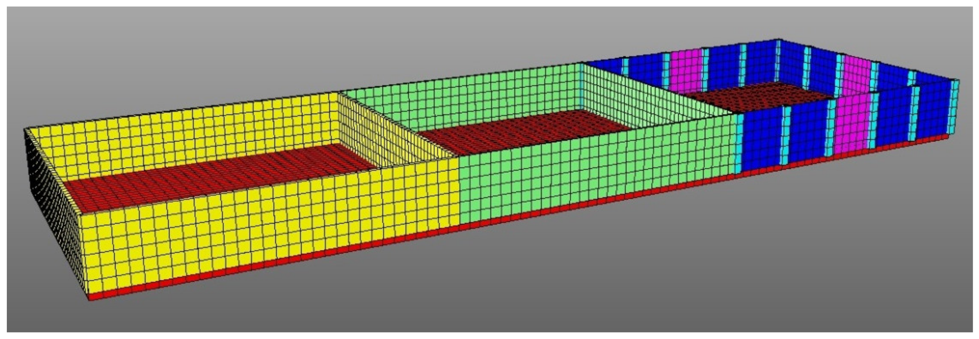
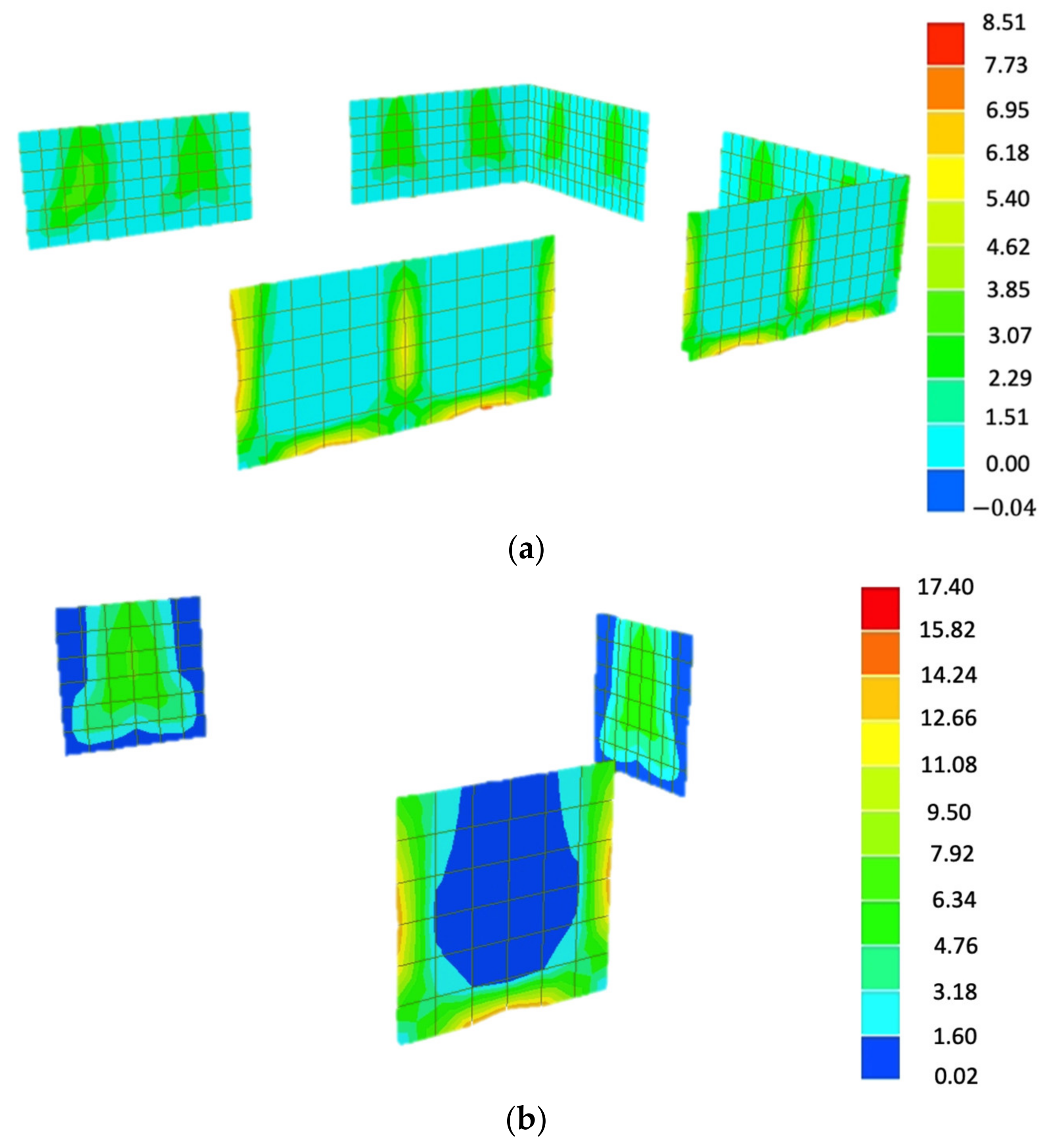
4.3. Computational Nonlinear Analysis
4.3.1. Description of the Analysis Method
4.3.2. Reinforced Ordinary Concrete Section (the First Basin)
4.3.3. UHDC Wall (Second Basin)
4.3.4. UHDC Precast Slab Supported by UHDC Columns
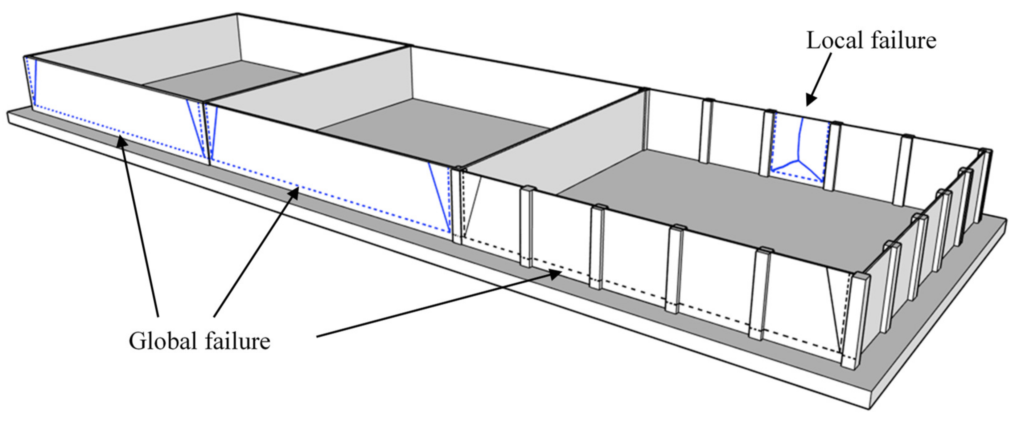
4.4. Moment–Displacement Analysis
5. Validation Tests on the Real Structure (EGP Pilot)
5.1. Steel Fibre Dispersion Survey
5.2. Water Height–Displacement Relationship
5.3. Crack Width and Water Tightness
6. Final Discussion and Conclusions
- Among the employed UHDC structural solutions, the 30 mm-thick UHDC slabs supported by 200 × 200 mm UHDC columns performed better than the 60 mm UHDC cast-in-place wall in terms of steel fiber distribution, material consumption and structural performance under service and ultimate limit states.
- The nonlinear analysis carried out on Basin 2 and Basin 3 shows that the maximum expected crack width is very low, thanks to the signature tensile behavior of the employed UHPC/UHDC materials, to the benefit of the durability and overall long-term performance of the structure. The importance of the serviceability limit state conditions in governing the design of the structure is highlighted, as long as the superior mechanical and durability performance of the material (and the release of minimum cover/thickness constraints due to the complete elimination of conventional reinforcement replaced by dispersed fibers) do allow for a significant reduction in structural thickness.
- Load vs. displacements relationship as obtained by means of computational nonlinear analysis reasonably fit the corresponding curves obtained during the validation tests, confirming the reliability of the adopted construction processes and technologies and analysis methods.
- The site observation and monitoring proved the ability of the UHDC materials to heal and seal the small cracks after being filled with geothermal water, with a healing index close to 80%.
- The sections designed by using the UHDC materials exhibited very good serviceability performance although a significant reduction in the section thickness was used. The nonlinear analysis also allowed to confirm that the crack widths and compression zone thickness may fulfil the tightness class requirements, once suitable adaption to UHPC/UHDC materials can be made, exactly upon confirmation of the experimental and modelling findings herein highlighted.
- The numerical structural analysis results along with ultimate yield line mechanisms indicate that the second basin 60 mm UHDC section and the third section 30 mm UHDC section stiffened by 200 × 200 mm2 UHDC columns can resist a hydrostatic pressure 1.5 times higher than the service load level before collapse.
Author Contributions
Funding
Institutional Review Board Statement
Informed Consent Statement
Data Availability Statement
Conflicts of Interest
References
- Younis, A.; Ebead, U.; Suraneni, P.; Nanni, A. Cost effectiveness of reinforcement alternatives for a concrete water chlorination tank. J. Build. Eng. 2020, 27, 100992. [Google Scholar] [CrossRef]
- D3.2—Definition of Key Durability Parameters for Each Scenario—ReSHEALience. Available online: https://uhdc.eu/documentation/d3-2-definition-of-key-durability-parameters-for-each-scenario/ (accessed on 21 September 2020).
- Thomas, M.; Bremner, T. Performance of lightweight aggregate concrete containing slag after 25 years in a harsh marine environment. Cem. Concr. Res. 2012, 42, 358–364. [Google Scholar] [CrossRef]
- Simultaneous Structural and Environmental Loading of an Ultra-High Performance Concrete Component|FHWA. Available online: https://highways.dot.gov/research/projects/simultaneous-structural-environmental-loading-ultra-high-performance-concrete-component (accessed on 13 June 2021).
- Krelani, V.; Krelani, V.; Moretti, F. Autogenous healing on the recovery of mechanical performance of High Performance Fibre Reinforced Cementitious Composites (HPFRCCs): Part 2—Correlation between healing of mechanical performance and crack sealing. Cem. Concr. Compos. 2016, 73, 299–315. [Google Scholar] [CrossRef]
- Ferrara, L.; Krelani, V.; Moretti, F.; Roig Flores, M.; Serna Ros, P. Effects of autogenous healing on the recovery of mechanical performance of High Performance Fibre Reinforced Cementitious Composites (HPFRCCs): Part 1. Cem. Concr. Compos. 2017, 83, 76–100. [Google Scholar] [CrossRef] [Green Version]
- Cuenca, E.; Ferrara, L. Self-healing capacity of fiber reinforced cementitious composites. State of the art and perspectives. KSCE J. Civ. Eng. 2017, 21, 2777–2789. [Google Scholar] [CrossRef]
- Yildirim, G.; Alyousif, A.; Şahmaran, M.; Lachemi, M. Assessing the self-healing capability of cementitious composites under increasing sustained loading. Adv. Cem. Res. 2015, 27, 581–592. [Google Scholar] [CrossRef]
- Woyciechowski, P.P.; Kalinowski, M. The influence of dosing method and material characteristics of superabsorbent polymers (SAP) on the effectiveness of the concrete internal curing. Materials 2018, 11, 1600. [Google Scholar] [CrossRef] [Green Version]
- Wang, Y.S.; Alrefaei, Y.; Dai, J.G. Silico-aluminophosphate and alkali-aluminosilicate geopolymers: A comparative review. Front. Mater. 2019, 6, 106. [Google Scholar] [CrossRef] [Green Version]
- Ferrara, L.; Ozyurt, N.; Di Prisco, M. High mechanical performance of fibre reinforced cementitious composites: The role of “casting-flow induced” fibre orientation. Mater. Struct. 2011, 44, 109–128. [Google Scholar] [CrossRef]
- Li, V.C.; Stang, H.; Krenchel, H. Micromechanics of crack bridging in fibre-reinforced concrete. Mater. Struct. 1993, 26, 486–494. [Google Scholar] [CrossRef]
- Al-Obaidi, S.; Bamonte, P.; Ferrara, L.; Luchini, M.; Mazzantini, I. Durability-based design of structures made with ultra-high-performance/ultra-high-durability concrete in extremely aggressive scenarios: Application to a geothermal water basin case study. Infrastructures 2020, 5, 102. [Google Scholar] [CrossRef]
- Borg, R.P.; Cuenca, E.; Garofalo, R.; Schillani, F.; Nasner, M.L.; Ferrara, L. Performance Assessment of Ultra-High Durability Concrete Produced From Recycled Ultra-High Durability Concrete. Front. Built Environ. 2021, 7, 78. [Google Scholar] [CrossRef]
- An Overview on H2020 Project “ReSHEALience”|Semantic Scholar. Available online: https://www.semanticscholar.org/paper/An-Overview-on-H2020-Project-“ReSHEALience”-Ferrara-Bamonte/9fc028915a762840ca6d11592b6acca013f4893b (accessed on 10 June 2021).
- Alexander, M.G.; Ballim, Y.; Stanish, K. A framework for use of durability indexes in performance-based design and specifications for reinforced concrete structures. Mater. Struct. Constr. 2008, 41, 921–936. [Google Scholar] [CrossRef]
- Alexander, M.G. Service life design and modelling of concrete structures—background, developments, and implementation. Rev. ALCONPAT 2018, 8, 224–245. [Google Scholar] [CrossRef]
- Simons, B. Concrete Performance Specifications: New Mexico Experience. Concr. Int. 2004, 26, 68–71. [Google Scholar]
- Perspective on Prescriptions. Available online: https://trid.trb.org/view/758581 (accessed on 13 June 2021).
- Bickley, J.A.; Hooton, R.D.; Hover, K.C. Performance Specifications for Durable Concrete. Concr. Int. 2006, 28, 51–57. [Google Scholar]
- Preparation of a Performance-Based Specification for Cast-in-Place Concrete. Available online: https://www.yumpu.com/en/document/read/25802659/preparation-of-a-performance-based-specification-for-cast-in-place- (accessed on 13 June 2021).
- Lo Monte, F.; Ferrara, L. Tensile behaviour identification in Ultra-High Performance Fibre Reinforced Cementitious Composites: Indirect tension tests and back analysis of flexural test results. Mater. Struct. Constr. 2020, 53, 1–12. [Google Scholar] [CrossRef]
- Cuenca, E.; D’Ambrosio, L.; Lizunov, D.; Tretjakov, A.; Volobujeva, O.; Ferrara, L. Mechanical properties and self-healing capacity of Ultra High Performance Fibre Reinforced Concrete with alumina nano-fibres: Tailoring Ultra High Durability Concrete for aggressive exposure scenarios. Cem. Concr. Compos. 2021, 118, 103956. [Google Scholar] [CrossRef]
- Cuenca, E.; Mezzena, A.; Ferrara, L. Synergy between crystalline admixtures and nano-constituents in enhancing autogenous healing capacity of cementitious composites under cracking and healing cycles in aggressive waters. Constr. Build. Mater. 2021, 266, 121447. [Google Scholar] [CrossRef]
- Materazzi, A.L.; Ubertini, F.; D’Alessandro, A. Carbon nanotube cement-based transducers for dynamic sensing of strain. Cem. Concr. Compos. 2013, 37, 2–11. [Google Scholar] [CrossRef]
- Cuenca, E.; Rigamonti, S.; Gastaldo Brac, E.M.; Ferrara, L. Crystalline admixture as healing promoter in concrete exposed to chloride-rich environments: An experimental study. ASCE J. Mater. Civ. Eng. 2020, in press. [Google Scholar] [CrossRef]
- Li, V.C.; Leung, C.K.Y. Steady-State and Multiple Cracking of Short Random Fiber Composites. J. Eng. Mech. 1992, 118, 2246–2264. [Google Scholar] [CrossRef] [Green Version]
- Naaman, A.E.; Reinhardt, H.W. Proposed classification of HPFRC composites based on their tensile response. Mater. Struct. Constr. 2006, 39, 547–555. [Google Scholar] [CrossRef]
- Shi, C.; Chen, B. (Eds.) Proceedings of the 2nd International Conference on UHPC Materials and Structures (UHPC2018-China), Fuzhou, China, 7–10 November 2018; RILEM Pubs: Fuzhou, China, 2018; p. 832.
- Li, V.C.; Mishra, D.K.; Wu, H.C. Matrix design for pseudo-strain-hardening fibre reinforced cementitious composites. Mater. Struct. 1995, 28, 586–595. [Google Scholar] [CrossRef]
- Upgrading the Concept of Uhpfrc for High Durability in the Cracked State: The Concept of Ultra High Durability Concrete (UHDC) in the Approach of the h2020 Project Reshealience—Core. Available online: https://core.ac.uk/display/195747484 (accessed on 13 June 2021).
- EN 1992-1-1: Eurocode 2: Design of concrete structures—Part 1-1: General rules and rules for buildings; CEN: Brussels, Belgium, 2004.
- NTC 2018: Norme tecniche per le costruzioni (Italian Guidelines for Constructions); Gazzeta Ufficiale: Rome, Italy, 2018; Volume 20.
- Lo Monte, F.; Ferrara, L. Characterization of the Tensile Behaviour of Ultra-High Performance Fibre-Reinforced Concrete. In Proceedings of the NBSC2019 Workshop, IMReady. Milan, Italy, 19–20 September 2019; pp. 45–54. [Google Scholar]
- Di Prisco, M.; Ferrara, L.; Lamperti, M.G.L. Double edge wedge splitting (DEWS): An indirect tension test to identify post-cracking behaviour of fibre reinforced cementitious composites. Mater. Struct. Constr. 2013, 46, 1893–1918. [Google Scholar] [CrossRef]
- Timoshenko, S.P.; Woinowsky-Krieger, S. Theory of Plates and Shells; McGraw-Hill: New York, NY, USA, 1959. [Google Scholar]
- Mander, J.B.; Priestley, M.J.N.; Park, R. Theoretical Stress-Strain Model for Confined Concrete. J. Struct. Eng. 1988, 114, 1804–1826. [Google Scholar] [CrossRef] [Green Version]
- Abdalla, H.M.; Karihaloo, B.L. A method for constructing the bilinear tension softening diagram of concrete corresponding to its true fracture energy. Mag. Concr. Res. 2004, 56, 597–604. [Google Scholar] [CrossRef]
- Ferrara, L.; Cremonesi, M.; Faifer, M.; Toscani, S.; Sorelli, L.; Baril, M.A.; Réthoré, J.; Baby, F.; Toutlemonde, F.; Bernardi, S. Structural elements made with highly flowable UHPFRC: Correlating computational fluid dynamics (CFD) predictions and non-destructive survey of fiber dispersion with failure modes. Eng. Struct. 2017, 133, 151–171. [Google Scholar] [CrossRef]
- Ferrara, L.; Faifer, M.; Toscani, S. A magnetic method for non destructive monitoring of fiber dispersion and orientation in steel fiber reinforced cementitious composites-part 1: Method calibration. Mater. Struct. Constr. 2012, 45, 575–589. [Google Scholar] [CrossRef]
- Ferrara, L.; Faifer, M.; Muhaxheri, M.; Toscani, S. A magnetic method for non destructive monitoring of fiber dispersion and orientation in steel fiber reinforced cementitious composites. Part 2: Correlation to tensile fracture toughness. Mater. Struct. Constr. 2012, 45, 591–598. [Google Scholar] [CrossRef]
- Destrée, X.; Yao, Y.; Mobasher, B. Sequential Cracking and Their Openings in Steel-Fiber-Reinforced Joint-Free Concrete Slabs. J. Mater. Civ. Eng. 2016, 28, 04015158. [Google Scholar] [CrossRef]
- EN 1992-1-1. Eurocode 2-Design of Concrete Structures-Part 3: Liquid Retaining and Containment Structures; CEN: Brussels, Belgium, 1992; Volume 4. [Google Scholar]
- Cuenca, E.; Tejedor, A.; Ferrara, L. A methodology to assess crack-sealing effectiveness of crystalline admixtures under repeated cracking-healing cycles. Constr. Build. Mater. 2018, 179, 619–632. [Google Scholar] [CrossRef]


| Constituents | XA-CA | XA-CA + ANF | XA-CA-CNC |
|---|---|---|---|
| CEM I 52,5 R (kg/m3) | 600 | 600 | 600 |
| Slag (kg/m3) | 500 | 500 | 500 |
| Water (liter/m3) | 200 | 200 | 200 |
| Steel fibers Azichem Readymesh 200® (kg/m3) | 120 | 120 | 120 |
| Sand 0–2 mm (kg/m3) | 982 | 982 | 982 |
| Superplasticizer Glenium ACE 300 ® (liter/m3) | 33 | 33 | 33 |
| Crystalline Admixture Penetron Admix ® (kg/m3) | 4.8 | 4.8 | 4.8 |
| Alumina nanofibers NAFEN® * (kg/m3) | - | 0.25 | - |
| Cellulose nanofibrils Navitas® * (kg/m3) | - | - | 0.15 |
| Oxide (wt.%) | CaO | SiO2 | Al2O3 | MgO | SO3 | Fe2O3 | TiO2 | Mn2O3 | K2O | Na2O | Other | LOI |
|---|---|---|---|---|---|---|---|---|---|---|---|---|
| PC | 59.7 | 19.5 | 4.9 | 3.3 | 3.4 | 3.5 | 0.2 | 0.1 | 0.8 | 0.2 | 0.4 | 2.5 |
| BFS | 39.2 | 38.9 | 10.2 | 6.4 | 1.3 | 0.4 | 0.6 | 0.3 | 0.5 | 0.8 | 0.3 | 1.2 |
| Basin | 1 (RC) | 2 (UHDC) | 3 (UHDC) |
|---|---|---|---|
| a (m) | ∞ | ∞ | 1.50 |
| b (m) | 1.50 | 1.50 | 1.50 |
| a/b | ∞ | ∞ | 1.00 |
| fcfm (MPa) | 3.10 | 9.60 | 9.60 |
| Mmax (kNm/m) | 5.63 | 5.63 | 1.01 |
| tmin (mm) | 104 | 59 | 25 |
| Basin | 1 | 2 | 3a | 3b |
|---|---|---|---|---|
| h (mm) | 100 | 60 | 30 | 20 |
| MSLS (kNm/m) | 3.67 | 3.67 | 0.67 | 0.67 |
| σc,max (MPa) | 2.17 | 6.13 | 4.45 | 12.86 |
| εt,max (‰) | 0.006 | 0.14 | 0.10 | 0.39 |
| wmax (μm) | - | 8 | - | 8 |
| Basin | 1 | 2 | 3a | 3b |
|---|---|---|---|---|
| t (mm] | 100 | 60 | 30 | 20 |
| Mu (kNm/m) | 14.0 | 10.08 | 2.52 | 1.12 |
| Mechanism | Global | Global | Global | Local |
| hw (m) | 2.63 | 1.90 | 2.55 | 2.28 |
| Class | Requirements for Leakage | Specific Requirements |
|---|---|---|
| 0 | Some degree of leakage acceptable, or leakage of liquids irrelevant. | Silos holding dry materials may generally be designed with this class. |
| 1 | Leakage to be limited to a small amount. Some surface staining or damp patches acceptable. | Any cracks expected to pass through the full thickness should be limited to wk1, Healing may be assumed if the expected range of strain under service condition is less than 150 × 10−6. |
| 2 | Leakage to be minimal. Appearance not to be impaired by cracks. | Cracks should not pass through the full width of a section, the design value of the depth of the compression zone should be at least xmin. xmin = min (50 mm or 0.2 h—h is the element thickness). |
| 3 | No leakage permitted. |
Publisher’s Note: MDPI stays neutral with regard to jurisdictional claims in published maps and institutional affiliations. |
© 2021 by the authors. Licensee MDPI, Basel, Switzerland. This article is an open access article distributed under the terms and conditions of the Creative Commons Attribution (CC BY) license (https://creativecommons.org/licenses/by/4.0/).
Share and Cite
Al-Obaidi, S.; Bamonte, P.; Animato, F.; Lo Monte, F.; Mazzantini, I.; Luchini, M.; Scalari, S.; Ferrara, L. Innovative Design Concept of Cooling Water Tanks/Basins in Geothermal Power Plants Using Ultra-High-Performance Fiber-Reinforced Concrete with Enhanced Durability. Sustainability 2021, 13, 9826. https://0-doi-org.brum.beds.ac.uk/10.3390/su13179826
Al-Obaidi S, Bamonte P, Animato F, Lo Monte F, Mazzantini I, Luchini M, Scalari S, Ferrara L. Innovative Design Concept of Cooling Water Tanks/Basins in Geothermal Power Plants Using Ultra-High-Performance Fiber-Reinforced Concrete with Enhanced Durability. Sustainability. 2021; 13(17):9826. https://0-doi-org.brum.beds.ac.uk/10.3390/su13179826
Chicago/Turabian StyleAl-Obaidi, Salam, Patrick Bamonte, Francesco Animato, Francesco Lo Monte, Iacopo Mazzantini, Massimo Luchini, Sandra Scalari, and Liberato Ferrara. 2021. "Innovative Design Concept of Cooling Water Tanks/Basins in Geothermal Power Plants Using Ultra-High-Performance Fiber-Reinforced Concrete with Enhanced Durability" Sustainability 13, no. 17: 9826. https://0-doi-org.brum.beds.ac.uk/10.3390/su13179826