
An Integrated Method to Evaluate Sustainability for Vulnerable Buildings Addressing Life Cycle Embodied Impacts and Resource Use


Abstract
:1. Introduction
1.1. Background
1.2. State of the Art of the Life Cycle Environmental Impact Assessment of Vulnerable Buildings

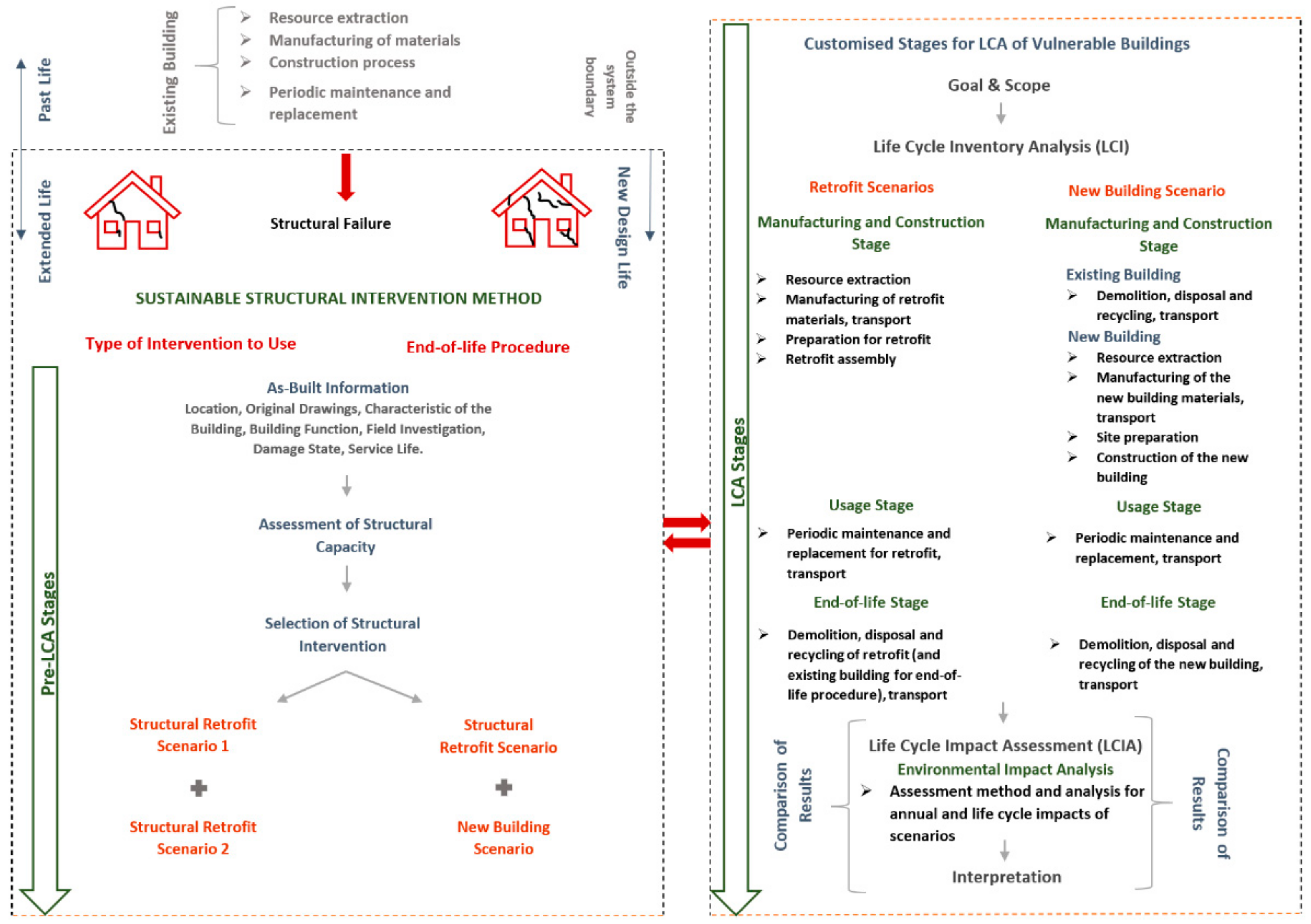
2. Proposed Sustainability Framework
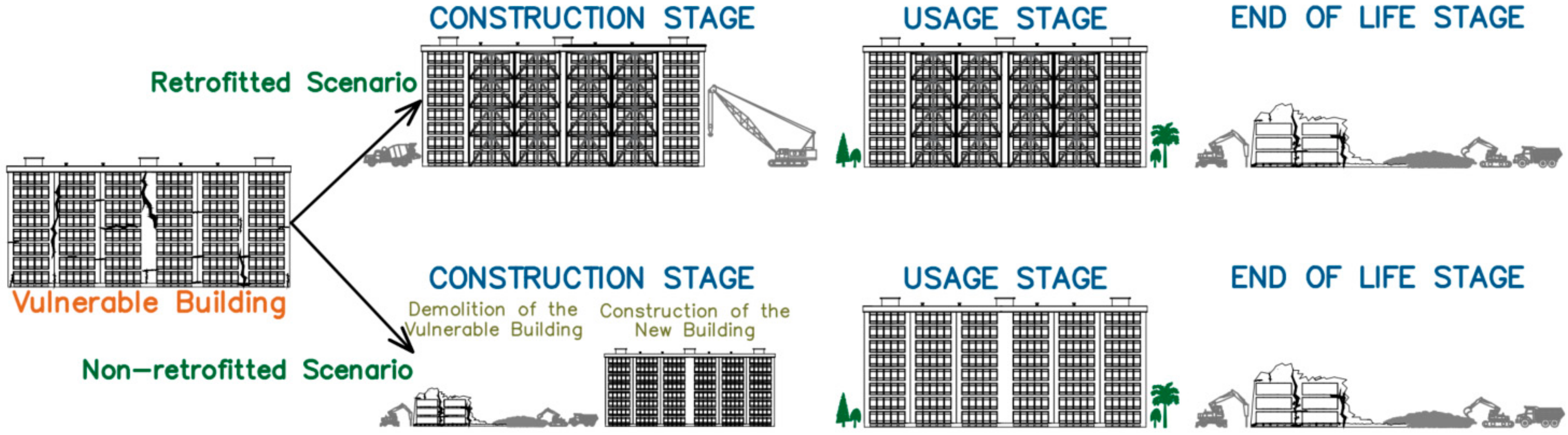
3. Type of Intervention to Use
3.1. Pre-LCA of the Low-Damaged Building
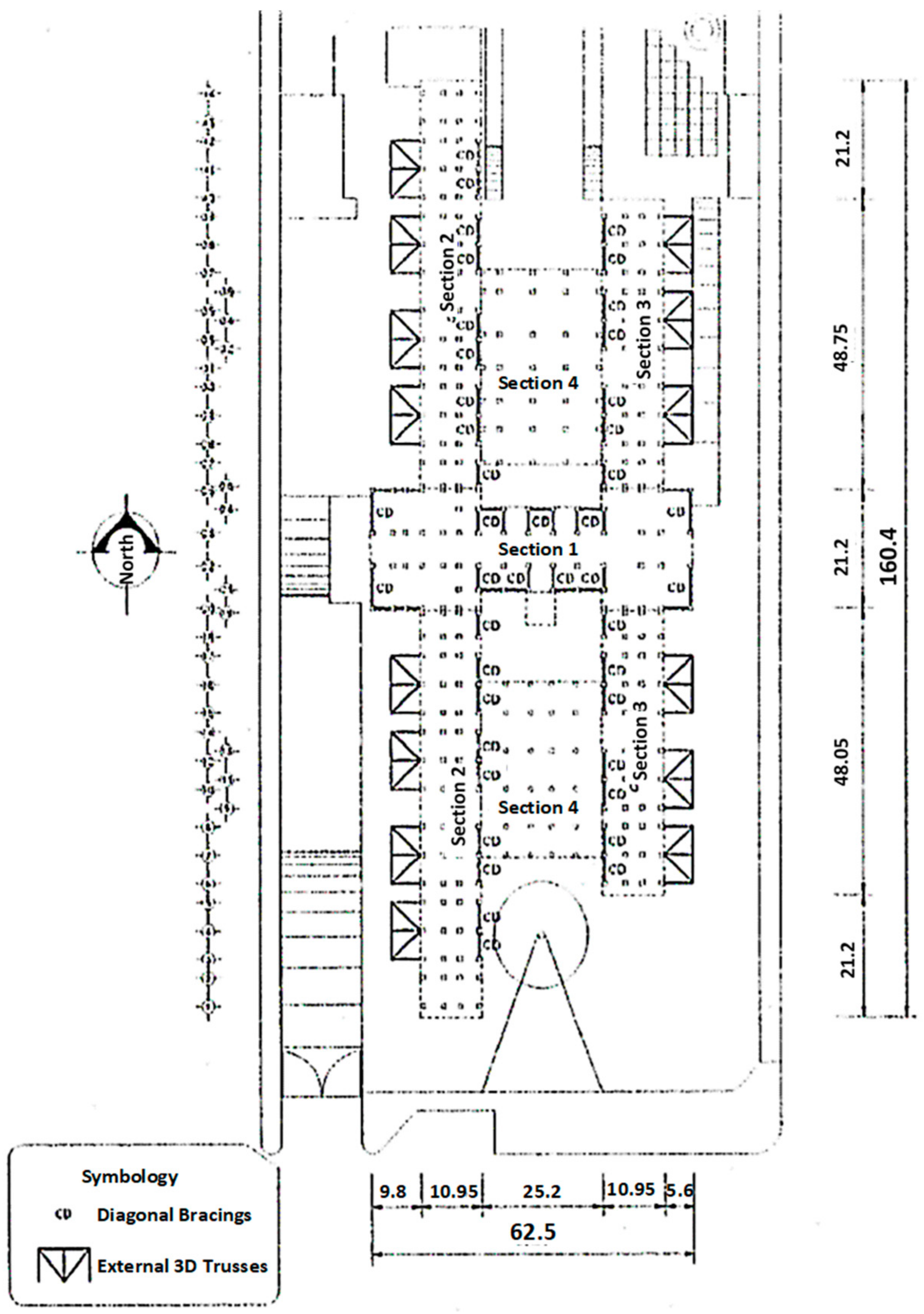
3.1.1. As-Built Information
3.1.2. Assessment of Structural Capacity
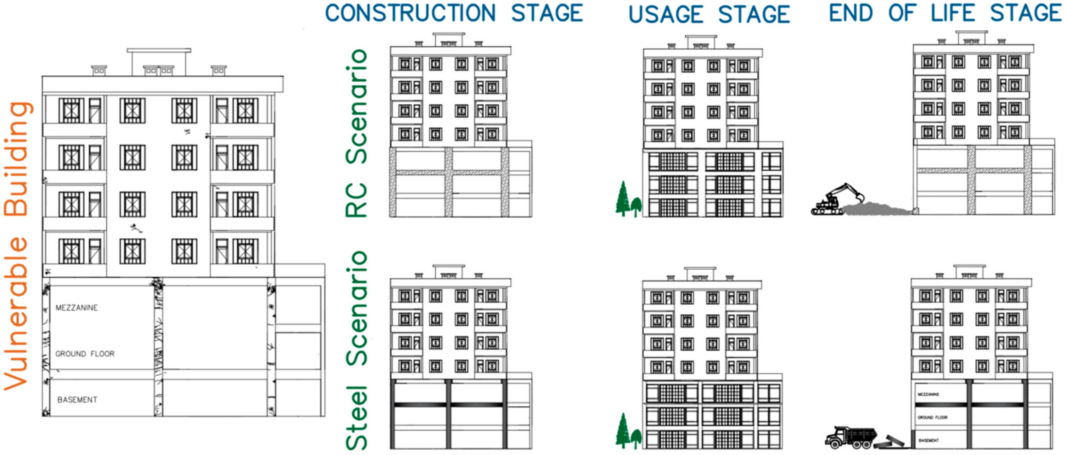
3.1.3. Selection of Structural Interventions
3.2. LCA of the Low-Damaged Building
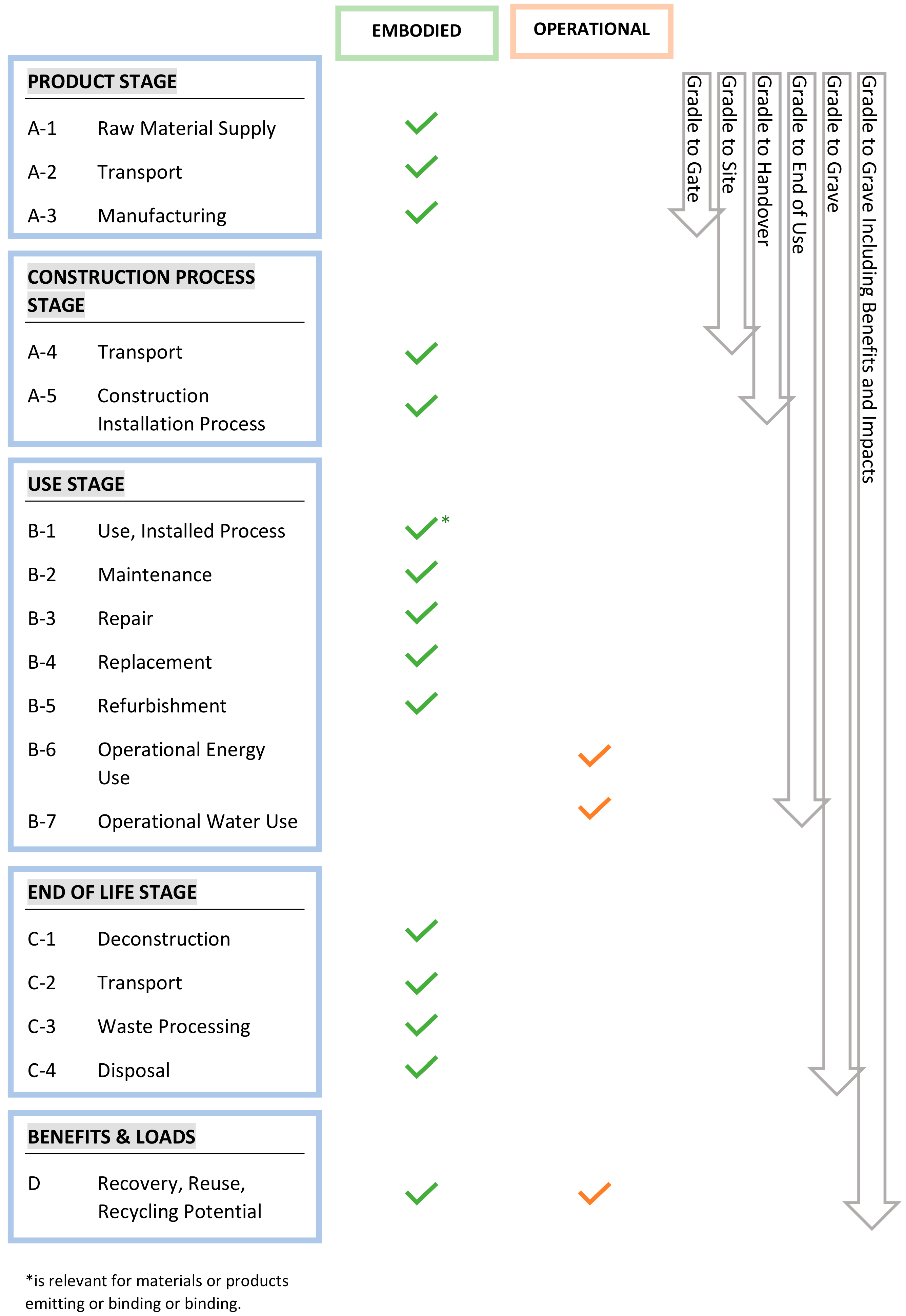
3.2.1. Goal and Scope
3.2.2. Life Cycle Inventory (LCI)
3.2.3. Life Cycle Impact Assessment (LCIA)
Resource Use Analysis Results
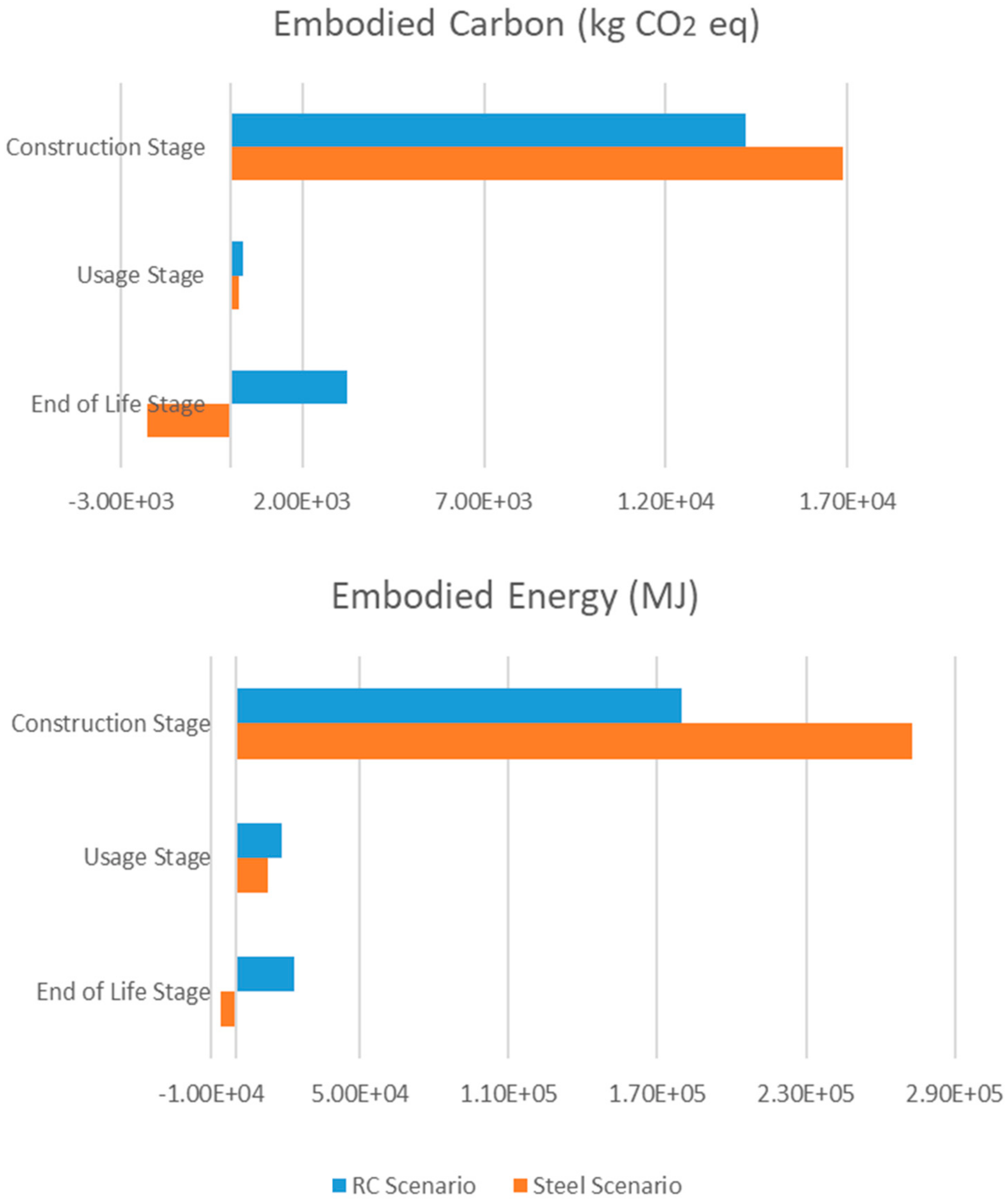
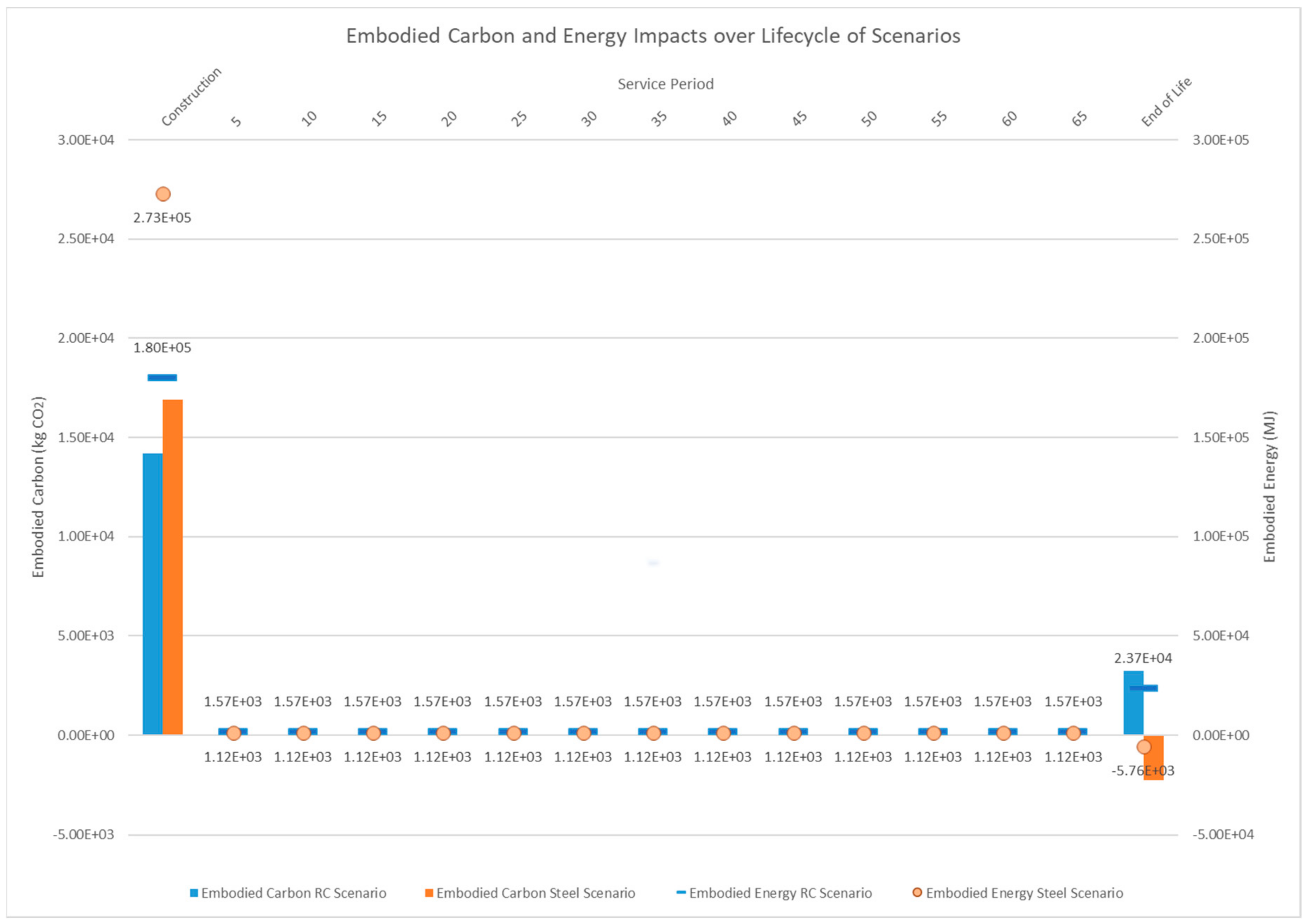
Embodied Carbon and Energy Analysis Results
3.2.4. Interpretation
4. End-of-Life Procedure
4.1. Pre-LCA of the Medium-Damaged Building
4.1.1. As-Built Information
4.1.2. Assessment of Structural Capacity
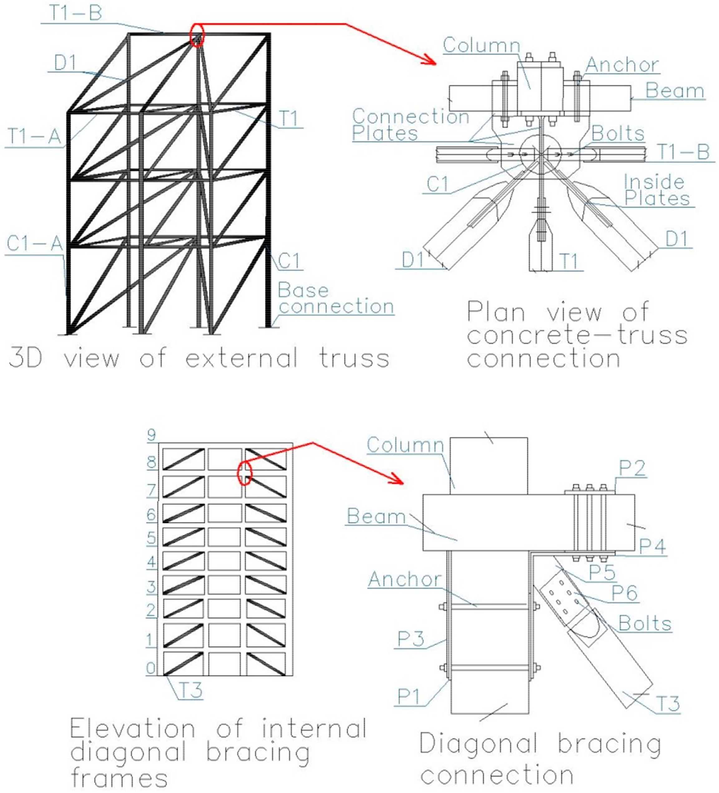
4.1.3. Selection of Structural Interventions
4.2. LCA of the Medium-Damaged Building
4.2.1. Goal and Scope
4.2.2. LCI
4.2.3. LCIA
Resource Use Analysis Results
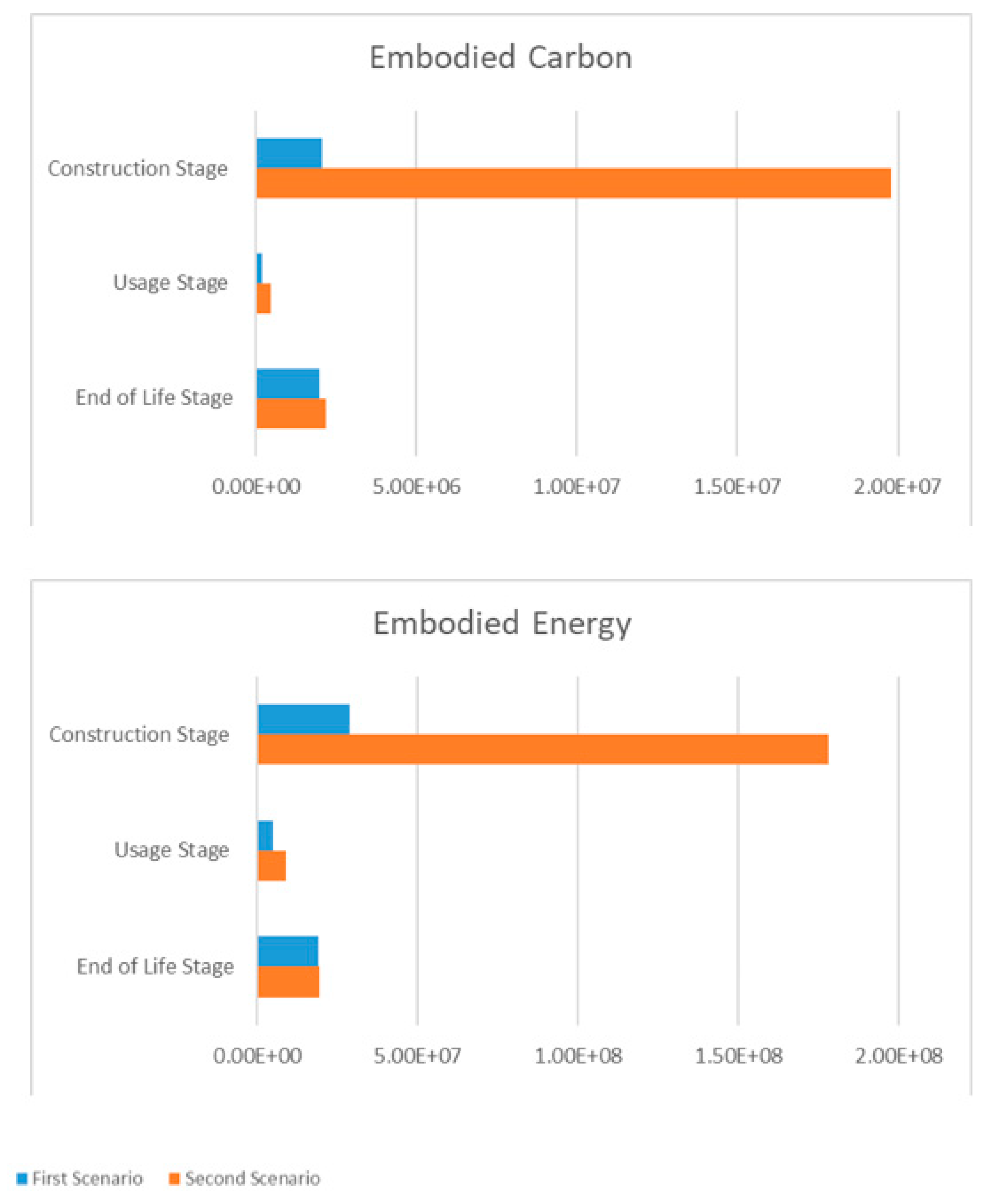
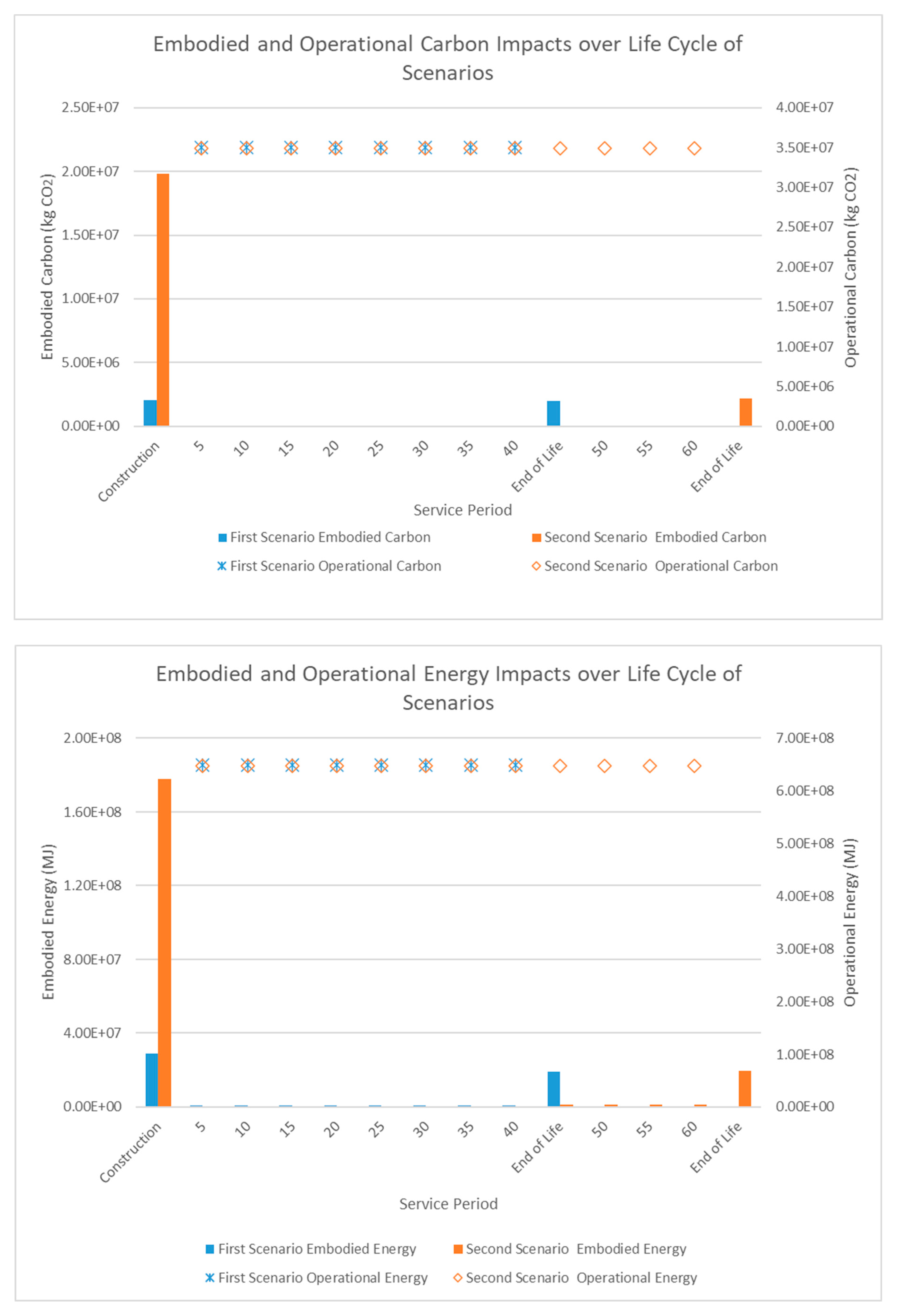
Embodied Carbon and Energy Analysis Results


| Scenarios | Impact Category | Unit | Site Preparation | Manufacturing of Retrofit | Construction of Retrofit | Total | |||||
|---|---|---|---|---|---|---|---|---|---|---|---|
| Disposal and Waste Processing | Transport | Manufacturing | Transport | Installation Process | Transport | Assembly of Retrofit | |||||
| First Scenario | E. Carbon | Kg CO2 eq | 1.95E+02 | 8.17E+01 | 1.74E+06 | 2.87E+03 | 6.25E+04 | 2.30E+05 | 7.14E+03 | 2.04E+06 | |
| E. Energy | MJ | 2.91E+03 | 1.19E+03 | 2.49E+07 | 4.19E+04 | 7.80E+05 | 3.27E+06 | 1.23E+05 | 2.91E+07 | ||
| Demolition of the Original Building | Manufacturing of the New Building | Construction of the New Building | Total | ||||||||
| Demolition, Disposal and Waste | Transport | Beyond Building Life | Manufacturing | Transport | Installation Process | Transport | |||||
| Second Scenario | E. Carbon | Kg CO2 eq | 6.62E+05 | 2.63E+05 | 1.10E+06 | 1.49E+07 | 1.01E+05 | 1.28E+06 | 1.48E+06 | 1.98E+07 | |
| E. Energy | MJ | 9.83E+06 | 3.83E+06 | 4.90E+06 | 1.23E+08 | 1.47E+06 | 1.37E+07 | 2.14E+07 | 1.78E+08 | ||
| Usage Stage | |||||||||||
| Maintenance Manufacturing | Transport | Maintenance Process | Operational Energy Use | Total | |||||||
| First Scenario | E. Carbon | Kg CO2 eq | 1.59E+05 | 2.81E+04 | 1.24E+03 | 2.80E+08 | 2.80E+08 | ||||
| E. Energy | MJ | 4.72E+06 | 4.08E+05 | 2.30E+04 | 5.19E+09 | 5.20E+09 | |||||
| Second Scenario | E. Carbon | Kg CO2 eq | 3.94E+05 | 5.68E+04 | - | 4.19E+08 | 4.20E+08 | ||||
| E. Energy | MJ | 8.40E+06 | 8.24E+05 | - | 7.78E+09 | 7.79E+09 | |||||
| Scenarios | Impact Category | Unit | End-of-Life Stage | Total | ||
| Deconstruction, Demolition, Disposal and Waste Processing | Transport | BBL Material | ||||
| First Scenario | E. Carbon | Kg CO2 eq | 7.15E+05 | 2.72E+05 | 9.92E+05 | 1.98E+06 |
| E. Energy | MJ | 1.06E+07 | 3.96E+06 | 4.39E+06 | 1.90E+07 | |
| Second Scenario | E. Carbon | Kg CO2 eq | 7.26E+05 | 2.88E+05 | 1.15E+06 | 2.16E+06 |
| E. Energy | MJ | 1.08E+07 | 4.20E+06 | 4.63E+06 | 1.96E+07 | |
| Impact Category | Scenarios | Unit | Total Impacts | Annual Impacts | Relative Comparison |
|---|---|---|---|---|---|
| Embodied Carbon | First Scenario | Kg CO2 eq | 4.21E+06 | 1.05E+05 | 72% Reduction |
| Second Scenario | Kg CO2 eq | 2.24E+07 | 3.73E+05 | 255% Increase | |
| Operational Carbon | First Scenario | Kg CO2 eq | 2.80E+08 | 7.00E+06 | 0.2% Increase |
| Second Scenario | Kg CO2 eq | 4.19E+08 | 6.98E+06 | 0.3% Reduction | |
| Embodied Energy | First Scenario | MJ | 5.33E+07 | 1.33E+06 | 61% Reduction |
| Second Scenario | MJ | 2.07E+08 | 3.45E+06 | 160% Increase | |
| Operational Energy | First Scenario | MJ | 5.19E+09 | 1.30E+08 | 0.06% Increase |
| Second Scenario | MJ | 7.78E+09 | 1.30E+08 | 0.06% Reduction |
4.2.4. Interpretation
5. Conclusions
Author Contributions
Funding
Data Availability Statement
Conflicts of Interest
References
- Coburn, A.; Sspence, R.J.S.; Pomonis, A. Vulnerability and Risk Assessment, 2nd ed.; Disaster Management Training Programme; UNDP/DHA: Geneva, Switzerland, 1994. [Google Scholar]
- Pîrvănuș, A.-M. Aspects on the Measures Applied at National Level for the Safety of Vulnerable Building Stock in Bucharest Municipality. Constructii 2020, 21, 40–47. [Google Scholar]
- EM-DAT. The Emergency Events Database; EM-DAT: Brussels, Belgium, 2019. [Google Scholar]
- Ritchie, H. Natural Disasters. Available online: https://ourworldindata.org/natural-disasters (accessed on 10 November 2020).
- Wei, H.-H.; Shohet, I.M.; Skibniewski, M.J.; Shapira, S.; Yao, X. Assessing the lifecycle sustainability costs and benefits of seismic mitigation designs for buildings. J. Archit. Eng. 2016, 22, 4015011. [Google Scholar] [CrossRef]
- Bhattacharya, S.; Nayak, S.; Dutta, S.C. A critical review of retrofitting methods for unreinforced masonry structures. Int. J. Disaster Risk Reduct. 2014, 7, 51–67. [Google Scholar] [CrossRef] [Green Version]
- Tucker, B.E. Reducing Earthquake Risk. Science 2013, 341, 1070–1072. [Google Scholar] [CrossRef] [PubMed]
- Bilham, R. The seismic future of cities. Bull. Earthq. Eng. 2009, 7, 839–887. [Google Scholar] [CrossRef] [Green Version]
- IEA International Energy Agency. Energy Efficiency: Buildings. Available online: https://www.iea.org/topics/energyefficiency/buildings/ (accessed on 7 September 2019).
- C40 Cities. The Net Zero Carbon Buildings Declaration. Available online: https://www.c40.org/other/net-zero-carbon-buildings-declaration (accessed on 7 November 2020).
- UN. Emissions Gap Report 2019; UN: New York, NY, USA, 2019. [Google Scholar]
- O’Connor, J. What Can We Do about Embodied Carbon? Canadian Architect: Toronto, ON, Canada, 2020; pp. 36–39. [Google Scholar]
- Chastas, P.; Theodosiou, T.; Bikas, D. Embodied energy in residential buildings-towards the nearly zero energy building: A literature review. Build. Environ. 2016, 105, 267–282. [Google Scholar] [CrossRef]
- BS EN 15978, Sustainability of Construction Works, Assessment of Environmental Performance of Buildings: Calculation Method. Available online: https://standards.iteh.ai/catalog/standards/cen/62c22cef-5666-4719-91f9-c21cb6aa0ab3/en-15978-2011 (accessed on 7 September 2021).
- International Energy Agency. Guideline for Design Professionals and Consultants Part 1: Basics for the Assessment of Embodied Energy and Embodied GHG Emissions Energy in Buildings and Communities Programme; International Energy Agency: Paris, France, 2016. [Google Scholar]
- Ramesh, T.; Prakash, R.; Shukla, K.K. Life cycle energy analysis of buildings: An overview. Energy Build. 2010, 42, 1592–1600. [Google Scholar] [CrossRef]
- Shrivastava, S.; Chini, A. Estimating energy consumption during construction of buildings: A contractor’s perspective. In Proceedings of the World Sustainable Building Conference, Helsinki, Finland, 18–21 October 2011; pp. 18–21. [Google Scholar]
- Dixit, M.K.; Fernández-Solís, J.L.; Lavy, S.; Culp, C.H. Identification of parameters for embodied energy measurement: A literature review. Energy Build. 2010, 42, 1238–1247. [Google Scholar] [CrossRef]
- OECD. Global Material Resources Outlook to 2060: Economic Drivers and Environmental Consequences; OECD: Paris, France, 2018. [Google Scholar]
- Rajagopalan, N.; Bilec, M.M.; Landis, A.E. Life cycle assessment evaluation of green product labeling systems for residential construction. Int. J. Life Cycle Assess. 2012, 17, 753–763. [Google Scholar] [CrossRef]
- Marini, A.; Passoni, C.; Belleri, A.; Feroldi, F.; Preti, M.; Metelli, G.; Riva, P.; Giuriani, E.; Plizzari, G. Combining seismic retrofit with energy refurbishment for the sustainable renovation of RC buildings: A proof of concept. Eur. J. Environ. Civ. Eng. 2017, 1–21. [Google Scholar] [CrossRef]
- Feroldi, F.; Marini, A.; Badiani, B.; Plizzari, G.A.; Giuriani, E.; Riva, P.; Belleri, A. Energy efficiency upgrading, architectural restyling and structural retrofit of modern buildings by means of “engineered” double skin façade. In Proceedings of the 2nd International Conference on Structures & Architecture (ICSA2013), Guimaraes, Portugal, 24–26 July 2013; pp. 1859–1866. [Google Scholar]
- Mora, T.D.; Righi, A.; Peron, F.; Romagnoni, P. Functional, Energy and Seismic Retrofitting in Existing Building: An Innovative System Based on xlam Technology. Energy Procedia 2015, 82, 486–492. [Google Scholar] [CrossRef] [Green Version]
- Georgescu, E.-S.; Georgescu, M.; Macri, Z.; Marino, E.; Margani, G.; Meita, V.; Pana, R.; Cascone, S.; Petran, H.; Rossi, P.; et al. Seismic and Energy Renovation: A Review of the Code Requirements and Solutions in Italy and Romania. Sustainability 2018, 10, 1561. [Google Scholar] [CrossRef] [Green Version]
- Basiricò, T.; Enea, D. Seismic and energy retrofit of the historic urban fabric of Enna (Italy). Sustainability 2018, 10, 1138. [Google Scholar] [CrossRef] [Green Version]
- De Vita, M.; Mannella, A.; Sabino, A.; Marchetti, A. Seismic Retrofit Measures for Masonry Walls of Historical Buildings, from an Energy Saving Perspective. Sustainability 2018, 10, 984. [Google Scholar] [CrossRef] [Green Version]
- Mora, T.D.; Pinamonti, M.; Teso, L.; Boscato, G.; Peron, F.; Romagnoni, P. Renovation of a school building: Energy retrofit and seismic upgrade in a school building in Motta Di Livenza. Sustainability 2018, 10, 969. [Google Scholar] [CrossRef] [Green Version]
- Lamperti Tornaghi, M.; Loli, A.; Negro, P. Balanced Evaluation of Structural and Environmental Performances in Building Design. Buildings 2018, 8, 52. [Google Scholar] [CrossRef] [Green Version]
- Loli, A.; Lamperti Tornaghi, M.; Negro, P. A method to include life-cycle analysis in earthquake design. In Proceedings of the 16th World Conference on Earthquake Engineering, Santiago, Chile, 9–13 January 2017. [Google Scholar]
- Rossi, B.; Marique, A.-F.; Reiter, S. Life-cycle assessment of residential buildings in three different European locations, case study. Build. Environ. 2012, 51, 402–407. [Google Scholar] [CrossRef]
- Wei, H.-H.; Skibniewski, M.J.; Shohet, I.M.; Yao, X. Lifecycle Environmental Performance of Natural-Hazard Mitigation for Buildings. J. Perform. Constr. Facil. 2016, 30, 04015042. [Google Scholar] [CrossRef]
- Menna, C.; Asprone, D.; Jalayer, F.; Prota, A.; Manfredi, G. Assessment of ecological sustainability of a building subjected to potential seismic events during its lifetime. Int. J. Life Cycle Assess. 2013, 18, 504–515. [Google Scholar] [CrossRef]
- Hasik, V.; Chhabra, J.P.S.; Warn, G.P.; Bilec, M.M. Review of approaches for integrating loss estimation and life cycle assessment to assess impacts of seismic building damage and repair. Eng. Struct. 2018, 175, 123–137. [Google Scholar] [CrossRef]
- Applied Technology Council for the Federal Emergency Management Agency. Techniques for the Seismic Rehabilitation of Existing Buildings; Applied Technology Council for the Federal Emergency Management Agency: Washington, DC, USA, 2006; Volume FEMA 547.
- Applied Technology Council for the Federal Emergency Management Agency. Next-Generation Methodology for Seismic Performance Assessment of Buildings; Applied Technology Council for the Federal Emergency Management Agency: Washington, DC, USA, 2012; Volume FEMA P-58.
- Welsh-Huggins, S.J.; Liel, A.B. A life-cycle framework for integrating green building and hazard-resistant design: Examining the seismic impacts of buildings with green roofs. Struct. Infrastruct. Eng. 2017, 13, 19–33. [Google Scholar] [CrossRef]
- Chiu, C.K.; Chen, M.R.; Chiu, C.H. Financial and Environmental Payback Periods of Seismic Retrofit Investments for Reinforced Concrete Buildings Estimated Using a Novel Method. J. Archit. Eng. 2013, 19, 112–118. [Google Scholar] [CrossRef]
- Feese, C.; Li, Y.; Bulleit, W.M. Assessment of Seismic Damage of Buildings and Related Environmental Impacts. J. Perform. Constr. Facil. 2015, 29, 04014106. [Google Scholar] [CrossRef] [Green Version]
- Padgett, J.E.; Li, Y. Risk-Based Assessment of Sustainability and Hazard Resistance of Structural Design. J. Perform. Constr. Facil. 2016, 30, 04014208. [Google Scholar] [CrossRef]
- Alirezaei, M.; Noori, M.; Tatari, O.; Mackie, K.R.; Elgamal, A. BIM-based Damage Estimation of Buildings under Earthquake Loading Condition. Procedia Eng. 2016, 145, 1051–1058. [Google Scholar] [CrossRef] [Green Version]
- Comber, M.V.; Poland, C.D. Disaster Resilience and Sustainable Design: Quantifying the Benefits of a Holistic Design Approach. In Proceedings of the Structures Congress, Pittsburgh, PA, USA, 2–4 May 2013; American Society of Civil Engineers: Reston, VA, USA, 2013; pp. 2717–2728. [Google Scholar]
- Simonen, K.; Merrifield, S.; Almufti, I.; Strobel, K.; Tipler, J. Integrating Environmental Impacts as Another Measure of Earthquake Performance for Tall Buildings in High Seismic Zones. In Proceedings of the Structures Congress, Portland, OR, USA, 23–25 April 2015; American Society of Civil Engineers: Reston, VA, USA, 2015; pp. 933–944. [Google Scholar]
- Welsh-Huggins, S.J.; Liel, A.B. Evaluating Multiobjective Outcomes for Hazard Resilience and Sustainability from Enhanced Building Seismic Design Decisions. J. Struct. Eng. 2018, 144, 04018108. [Google Scholar] [CrossRef]
- Simonen, K.; Huang, M.; Aicher, C.; Morris, P. Embodied carbon as a proxy for the environmental impact of earthquake damage repair. Energy Build. 2018, 164, 131–139. [Google Scholar] [CrossRef]
- Sarkisian, M.P. Design of environmentally responsible structures in regions of high seismic risk. Struct. Infrastruct. Eng. 2014, 10, 849–864. [Google Scholar] [CrossRef]
- Welsh-Huggins, S.J.; Liel, A.B. Integrating hazard-induced damage and environmental impacts in building life-cycle assessments. In Proceedings of the 2014 International Symposium of Life-Cycle Civil Engineering, Tokyo, Japan, 16–19 November 2014. [Google Scholar]
- Belleri, A.; Marini, A. Does seismic risk affect the environmental impact of existing buildings? Energy Build. 2016, 110, 149–158. [Google Scholar] [CrossRef]
- Hossain, K.A.; Gencturk, B. Life-Cycle Environmental Impact Assessment of Reinforced Concrete Buildings Subjected to Natural Hazards. J. Archit. Eng. 2016, 22, A4014001. [Google Scholar] [CrossRef]
- Gencturk, B.; Hossain, K.; Lahourpour, S. Life cycle sustainability assessment of RC buildings in seismic regions. Eng. Struct. 2016, 110, 347–362. [Google Scholar] [CrossRef]
- Chhabra, J.P.S.; Hasik, V.; Bilec, M.M.; Warn, G.P. Probabilistic Assessment of the Life-Cycle Environmental Performance and Functional Life of Buildings due to Seismic Events. J. Archit. Eng. 2018, 24, 04017035. [Google Scholar] [CrossRef]
- Menna, C.; Caruso, M.C.; Asprone, D.; Prota, A. Environmental sustainability assessment of structural retrofit of masonry buildings based on LCA. Eur. J. Environ. Civ. Eng. 2016, 1–10. [Google Scholar] [CrossRef]
- Terracciano, G.; Di Lorenzo, G.; Formisano, A.; Landolfo, R. Cold-formed thin-walled steel structures as vertical addition and energetic retrofitting systems of existing masonry buildings. Eur. J. Environ. Civ. Eng. 2015, 19, 850–866. [Google Scholar] [CrossRef] [Green Version]
- Napolano, L.; Menna, C.; Asprone, D.; Prota, A.; Manfredi, G. LCA-based study on structural retrofit options for masonry buildings. Int. J. Life Cycle Assess. 2015, 20, 23–35. [Google Scholar] [CrossRef] [Green Version]
- Ferreira, J.; Duarte Pinheiro, M.; de Brito, J. Economic and environmental savings of structural buildings refurbishment with demolition and reconstruction—A Portuguese benchmarking. J. Build. Eng. 2015, 3, 114–126. [Google Scholar] [CrossRef]
- Vitiello, U.; Salzano, A.; Asprone, D.; Di Ludovico, M.; Prota, A. Life-cycle assessment of seismic retrofit strategies applied to existing building structures. Sustainability 2016, 8, 1275. [Google Scholar] [CrossRef] [Green Version]
- Formisano, A.; Chiumiento, G.; Di Lorenzo, G.; Landolfo, R. Innovative and traditional seismic retrofitting techniques of an exisiting RC school building: Life cycle assessment and performance ranking through the TOPSIS method. Constr. Met. 2017, 84–93. Available online: https://www.researchgate.net/publication/316845993_Innovative_and_traditional_seismic_retrofitting_techniques_of_an_existing_RC_school_building_life_cycle_assessment_and_performance_ranking_through_the_TO_PSIS_method (accessed on 7 September 2021).
- Uzun, E.T.; Secer, M. Evaluation of Building Retrofitting Alternatives from Sustainability Perspective. Procedia Eng. 2017, 171, 1137–1146. [Google Scholar] [CrossRef]
- Ribakov, Y.; Halperin, I.; Pushkar, S. Seismic Resistance and Sustainable Performance of Retrofitted Buildings by Adding Stiff Diaphragms or Seismic Isolation. J. Archit. Eng. 2018, 24, 04017028. [Google Scholar] [CrossRef]
- Dattilo, C.; Negro, P.; Landolfo, R. An Integrated Approach for Sustainability (IAS): Life Cycle Assessment (LCA) as a Supporting Tool for Life Cycle Costing (LCC) and Social Issues. In Proceedings of the International Conference on on Sustainable Building and Affordable To All, Algarve, Portugal, 17–19 March 2010; pp. 721–728. [Google Scholar]
- Lützkendorf, T.; Balouktsi, M.; Frischknecht, R. Evaluation of Embodied Energy and CO2eq for Building Construction (Annex 57), Subtask 1: Basics, Actors and Concepts; International Energy Agency: Paris, France, 2016. [Google Scholar]
- Keskin, F.S.; Martinez-Vazquez, P.; Baniotopoulos, C. Sustainable structural intervention methodology for vulnerable buildings from a lifecycle perspective. In Proceedings of the IOP Conference Series: Earth and Environmental Science, Thessaloniki, Greece, 23–25 October 2019; p. 012051. [Google Scholar]
- ISO. Environmental Management—Life Cycle Assessment—Principles and Framework. 2006, pp. 1–20. Available online: https://www.iso.org/standard/37456.html (accessed on 7 September 2021).
- FEMA. Seismic Performance Assessment of Buildings, Methodology for Assessing Environmental Impacts; FEMA: Washington, DC, USA, 2012; Volume FEMA P-58-4, pp. 1–271.
- Romano, E.; Negro, P.; Taucer, F. Seismic Performance Assessment Addressing Sustainability and Energy Efficiency; Publications Office of the European Union: Paris, France, 2014; Volume EUR 26432. [Google Scholar]
- Beyhan, G.; Keskinsezer, A.; Kafadar, Ö. Analysis of strong ground motion data from the Van earthquake (Turkey), 2011. Geomech. Geophys. Geo-Energy Geo-Resour. 2019, 5, 253–270. [Google Scholar] [CrossRef]
- Marteinsson, B. Service Life Estimation in the Design of Buildings: A Development of the Factor Method. Ph.D. Thesis, University of Gävle, Gavle, Sweden, 2005. [Google Scholar]
- Soronis, G. Standards for design life of buildings: Utilization in the design process. Constr. Build. Mater. 1996, 10, 487–490. [Google Scholar] [CrossRef]
- Hernández-Moreno, S. The Method By Factors To Estimate Service Life in Uildings Projects According To Norm Iso 15686. Manag. Res. Pract. 2012, 4, 5–11. [Google Scholar]
- ASMI. Life Cycle Assessment of UBC Biological Sciences Complex Renew Project; ASMI: Ottawa, ON, Canada, 2011. [Google Scholar]
- Athena Sustainable Materials Institute. ASMI Technical Details. Available online: http://www.athenasmi.org/resources/about-lca/technical-details/ (accessed on 4 October 2020).
- Athena Sustainable Materials Institute. Athena Impact Estimator for Buildings V 4.5 Users Manual, Software and Database Overview; Athena Sustainable Materials Institute: Ottawa, ON, Canada, 2013. [Google Scholar]
- Athena Sustainable Materials Institute. Impact Estimator for Buildings. Available online: https://calculatelca.com/software/impact-estimator/ (accessed on 2 October 2020).
- Hauke, B.; Siebers, R. Life Cycle Assessment Comparison of a Typical Single Storey Building; bauforumstah: Düsseldorf, Germany, 2011. [Google Scholar]
- Martinez Vazquez, P. Procedimiento de Construccion del Refuerzo Exterior de Hospital 20 de Noviembre (Construction Procedure of the External Reinforcement of Hospital November 20). Bachelor’s Thesis, Universidad Nacional Autonoma de Mexico, Mexico City, Mexico, 1995. [Google Scholar]
- Almanza, L.M. Proyecto Del Refuerzo Estructural Interior a Base De Contraventeos Metalicos Del Hospital 20 De Noviembre, En La Ciudad De Mexico (Project of the Interior Structural Reinforcement Based on Metallic Buttresses of the 20 de Noviembre Hospital, in Mexico City). Bachelor’s Thesis, Universidad Nacional Autonoma de Mexico, Mexico City, Mexico, 1996. [Google Scholar]
- Morán-Rodríguez, S.; Novelo-Casanova, D.A. A methodology to estimate seismic vulnerability of health facilities. Case study: Mexico City, Mexico. Nat. Hazards 2018, 90, 1349–1375. [Google Scholar] [CrossRef]
- RCDF. Normas Tecnicas Complementarias del Reglamento de Construcciones Para el Distrito Federal (Complementary Technical Norms of the Construction Regulations for the Federal District); RCDF: Mexico City, Mexico, 1987; pp. 1–287. [Google Scholar]
- Meléndez, R.G. Costos Paramétricos (Parametric Costs); Instituto Mexicano de Ingeniería de Costos: Mexico City, Mexico, 2014; ISBN 0319990804094. [Google Scholar]
- PEEB. Building Sector Brief: Mexico; PEEB: Programme for Energy Efficiency in Buildings: Paris, France, 2018. [Google Scholar]
- Ji, R.; Qu, S. Investigation and evaluation of energy consumption performance for hospital buildings in China. Sustainability 2019, 11, 1724. [Google Scholar] [CrossRef] [Green Version]


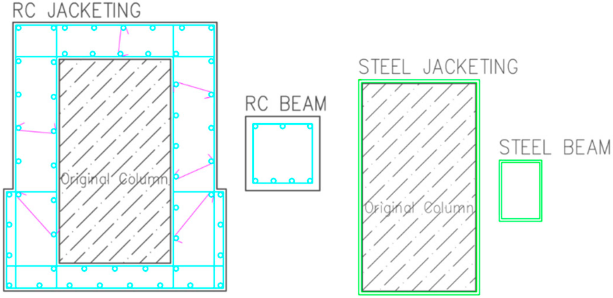
| RC Scenario | Steel Scenario |
|---|---|
| RC jacketing (9 columns) | Steel jacketing (11 columns) |
| RC beam additions (3 of them 40 × 40 cm and 1 of them 70 × 32 cm) for the ground floor | Steel beam additions for the ground floor (hollow structural steel with 10 mm thickness) and U-shaped plates to the column-beam joints in the mezzanine floor |
| CFPR application to deflected beams and cracked ceiling concrete | CFPR application to deflected beams and cracked ceiling concrete |
| Epoxy application to cracks | Epoxy application to cracks |
| Material | Unit | Resource Use | |
|---|---|---|---|
| RC Scenario | Steel Scenario | ||
| Ash | kg | 5.57E+01 | 2.25E+01 |
| Bauxite | kg | 2.64E+01 | 2.44E+00 |
| Carbon dioxide, in air | kg | 4.16E+02 | 1.72E+02 |
| Clay and shale | kg | 1.18E+02 | 1.09E+01 |
| Coal | kg | 3.04E+03 | 2.85E+03 |
| Coarse aggregate | kg | 5.40E+04 | 2.81E+03 |
| Crude oil | L | 1.38E+03 | 5.93E+02 |
| Crude oil as feedstock | L | 1.85E+02 | 1.31E+02 |
| Dolomite | kg | 3.95E+02 | 7.95E+02 |
| Ferrous scrap | kg | 6.09E+03 | 1.05E+04 |
| Gypsum (natural) | kg | 3.91E+02 | 3.78E+01 |
| Gypsum (synthetic) | kg | 4.79E+01 | 1.90E+01 |
| Iron ore | kg | 2.70E+03 | 2.17E+03 |
| Lignite | kg | 6.73E+01 | 2.67E+02 |
| Limestone | kg | 1.14E+04 | 2.00E+03 |
| Natural gas | m3 | 7.71E+02 | 2.06E+03 |
| Natural gas as feedstock | m3 | 2.48E+02 | 1.55E+02 |
| Other | kg | 9.56E+02 | 2.89E+02 |
| Peat | kg | 6.55E−02 | 2.26E−02 |
| Sand | kg | 7.77E−04 | 2.84E−04 |
| Tin ore | kg | 2.66E−06 | 3.96E−07 |
| Uranium | kg | 2.35E−02 | 3.89E−02 |
| Water | L | 1.88E+05 | 1.50E+05 |
| Wood fiber | kg | 9.89E+02 | 1.55E+01 |
| Scenarios | Impact Category | Unit | Site Preparation | Manufacturing Process | Construction Process | Total | ||||
|---|---|---|---|---|---|---|---|---|---|---|
| Disposal and Waste Processing | Transport | Manufacturing | Transport | Installation Process | Transport | Assembly of Retrofit | ||||
| RC Scenario | E. Carbon | Kg CO2 eq | 1.54E+01 | 1.13E+01 | 1.25E+04 | 1.03E+02 | 1.03E+03 | 4.81E+02 | 2.09E+00 | 1.42E+04 |
| E. Energy | MJ | 2.30E+02 | 1.65E+02 | 1.59E+05 | 1.51E+03 | 1.19E+04 | 6.97E+03 | 2.76E+02 | 1.80E+05 | |
| Steel Scenario | E. Carbon | Kg CO2 eq | 1.44E+01 | 1.10E+01 | 1.63E+04 | 7.36E-01 | 3.62E+02 | 1.63E+02 | 1.29E+01 | 1.69E+04 |
| E. Energy | MJ | 2.15E+02 | 1.60E+02 | 2.64E+05 | 1.07E+01 | 5.02E+03 | 2.37E+03 | 1.70E+03 | 2.73E+05 | |
| Usage Stage | Usage Stage | |||||||||
| Scenarios | Impact Category | Unit | Maintenance Manufacturing | Transport | Total | Scenario | Impact Category | Maintenance Manufacturing | Transport | Total |
| RC Scenario | E. Carbon | Kg CO2 eq | 3.46E+02 | 2.37E+01 | 3.70E+02 | Steel Scenario | E. Carbon | 2.40E+02 | 1.62E+01 | 2.56E+02 |
| E. Energy | MJ | 1.85E+04 | 3.44E+02 | 1.88E+04 | E. Energy | 1.30E+04 | 2.35E+02 | 1.33E+04 | ||
| End-of-Life Stage | ||||||||||
| Scenarios | Impact Category | Unit | Deconstruction, Demolition, Disposal and Waste Processing | Transport | BBL Material | Total | ||||
| RC Scenario | E. Carbon | Kg CO2 eq | 5.54E+02 | 2.17E+02 | 2.46E+03 | 3.23E+03 | ||||
| E. Energy | MJ | 8.20E+03 | 3.16E+03 | 1.23E+04 | 2.37E+04 | |||||
| Steel Scenario | E. Carbon | Kg CO2 eq | 4.54E+02 | 1.52E+01 | −2.74E+03 | −2.27E+03 | ||||
| E. Energy | MJ | 6.61E+03 | 2.22E+02 | −1.26E+04 | −5.76E+03 | |||||
| Impact Category | Scenarios | Unit | Total Impacts | Annual Impacts | Relative Comparison |
|---|---|---|---|---|---|
| Embodied Carbon | RC Scenario | Kg CO2 eq | 1.78E+04 | 2.74E+02 | 20% Increase |
| Steel Scenario | Kg CO2 eq | 1.49E+04 | 2.29E+02 | 16% Reduction | |
| Embodied Energy | RC Scenario | MJ | 2.23E+05 | 3.42E+03 | 20% Reduction |
| Steel Scenario | MJ | 2.81E+05 | 4.32E+03 | 26% Increase |
| Material | Unit | Resource Use | |
|---|---|---|---|
| First Scenario | Second Scenario | ||
| Aluminium scrap | kg | 7.36E+03 | 2.47E+04 |
| Ash | kg | 3.63E+01 | 0 |
| Bauxite | kg | −2.12E+04 | −6.02E+04 |
| Carbon dioxide, in air | kg | 1.91E+04 | 6.24E+04 |
| Clay and shale | kg | 1.50E+04 | 4.47E+05 |
| Coal | kg | 8.88E+05 | 3.04E+06 |
| Coarse aggregate | kg | 2.13E+06 | 7.35E+07 |
| Crude oil | L | 4.71E+05 | 2.08E+06 |
| Crude oil as feedstock | L | 3.05E+04 | 4.73E+04 |
| Dolomite | kg | 9.77E+04 | 2.14E+05 |
| Ferrous scrap | kg | 9.54E+05 | 2.89E+06 |
| Gypsum (natural) | kg | 1.57E+04 | 4.63E+05 |
| Gypsum (synthetic) | kg | 6.67E+01 | 1.03E+03 |
| Iron ore | kg | 1.30E+06 | 2.28E+06 |
| Lignite | kg | −2.64E+04 | −5.63E+04 |
| Limestone | kg | 5.52E+05 | 1.54E+07 |
| Natural gas | m3 | 1.53E+05 | 6.73E+05 |
| Natural gas as feedstock | m3 | 4.09E+04 | 6.34E+04 |
| Other | kg | 8.94E+04 | 8.31E+05 |
| Peat | kg | 3.83E+00 | 1.25E+02 |
| Potash | kg | 2.94E+02 | 1.12E+03 |
| Sand | kg | −2.13E+02 | −5.48E+02 |
| Tin ore | kg | 3.92E-04 | 1.19E-02 |
| Uranium | kg | 1.25E+00 | 1.41E+01 |
| Water | L | 2.70E+07 | 1.72E+08 |
| Wood fiber | kg | 1.23E+04 | 3.65E+05 |
Publisher’s Note: MDPI stays neutral with regard to jurisdictional claims in published maps and institutional affiliations. |
© 2021 by the authors. Licensee MDPI, Basel, Switzerland. This article is an open access article distributed under the terms and conditions of the Creative Commons Attribution (CC BY) license (https://creativecommons.org/licenses/by/4.0/).
Share and Cite
Keskin, F.S.; Martinez-Vazquez, P.; Baniotopoulos, C. An Integrated Method to Evaluate Sustainability for Vulnerable Buildings Addressing Life Cycle Embodied Impacts and Resource Use. Sustainability 2021, 13, 10204. https://0-doi-org.brum.beds.ac.uk/10.3390/su131810204
Keskin FS, Martinez-Vazquez P, Baniotopoulos C. An Integrated Method to Evaluate Sustainability for Vulnerable Buildings Addressing Life Cycle Embodied Impacts and Resource Use. Sustainability. 2021; 13(18):10204. https://0-doi-org.brum.beds.ac.uk/10.3390/su131810204
Chicago/Turabian StyleKeskin, Fatma Seyma, Pedro Martinez-Vazquez, and Charalampos Baniotopoulos. 2021. "An Integrated Method to Evaluate Sustainability for Vulnerable Buildings Addressing Life Cycle Embodied Impacts and Resource Use" Sustainability 13, no. 18: 10204. https://0-doi-org.brum.beds.ac.uk/10.3390/su131810204