
Experimental Investigation on Axial Compression of Resilient Nail-Cross-Laminated Timber Panels


Abstract
:1. Introduction
2. Materials and Methods
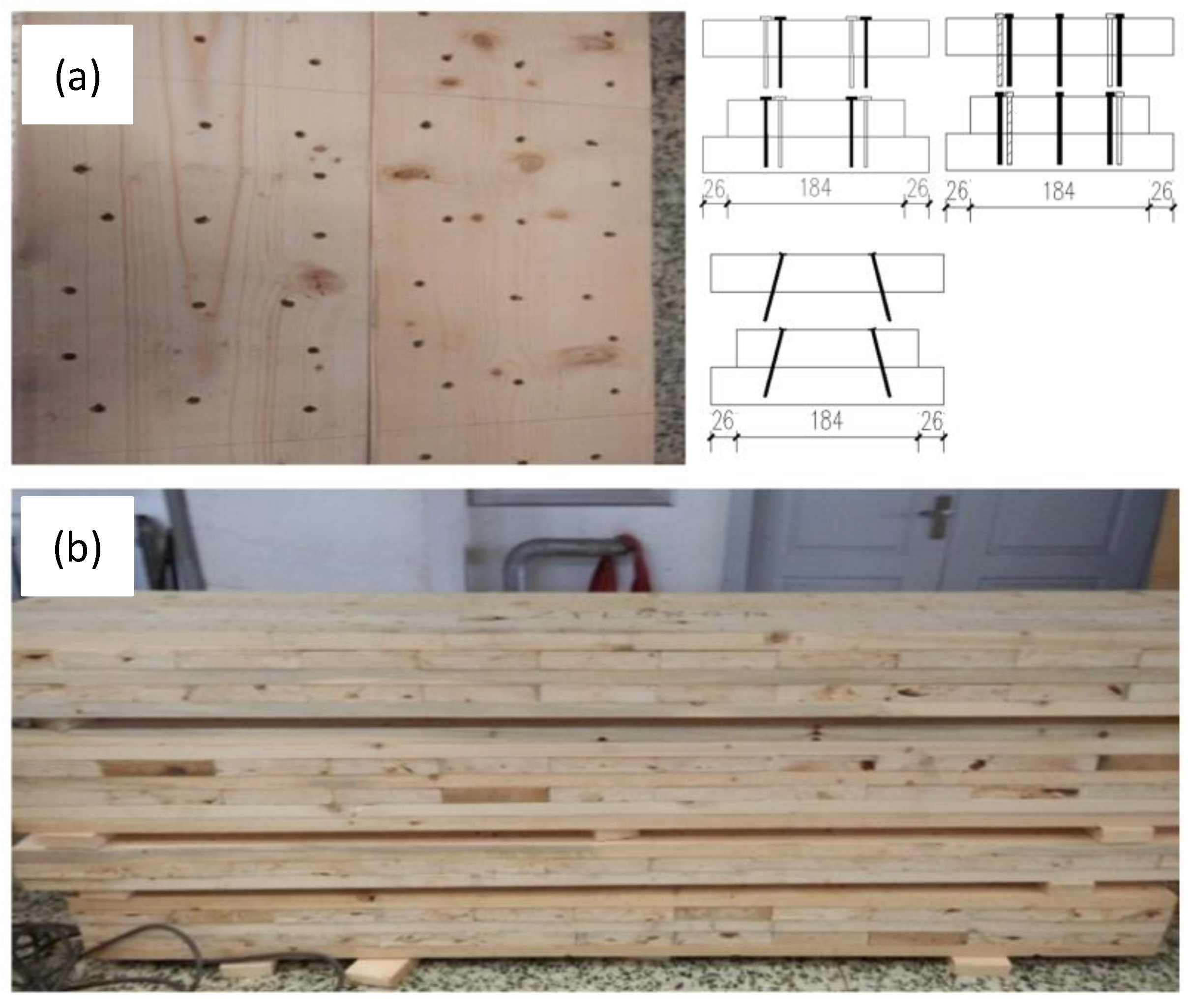
2.1. Test Specimens
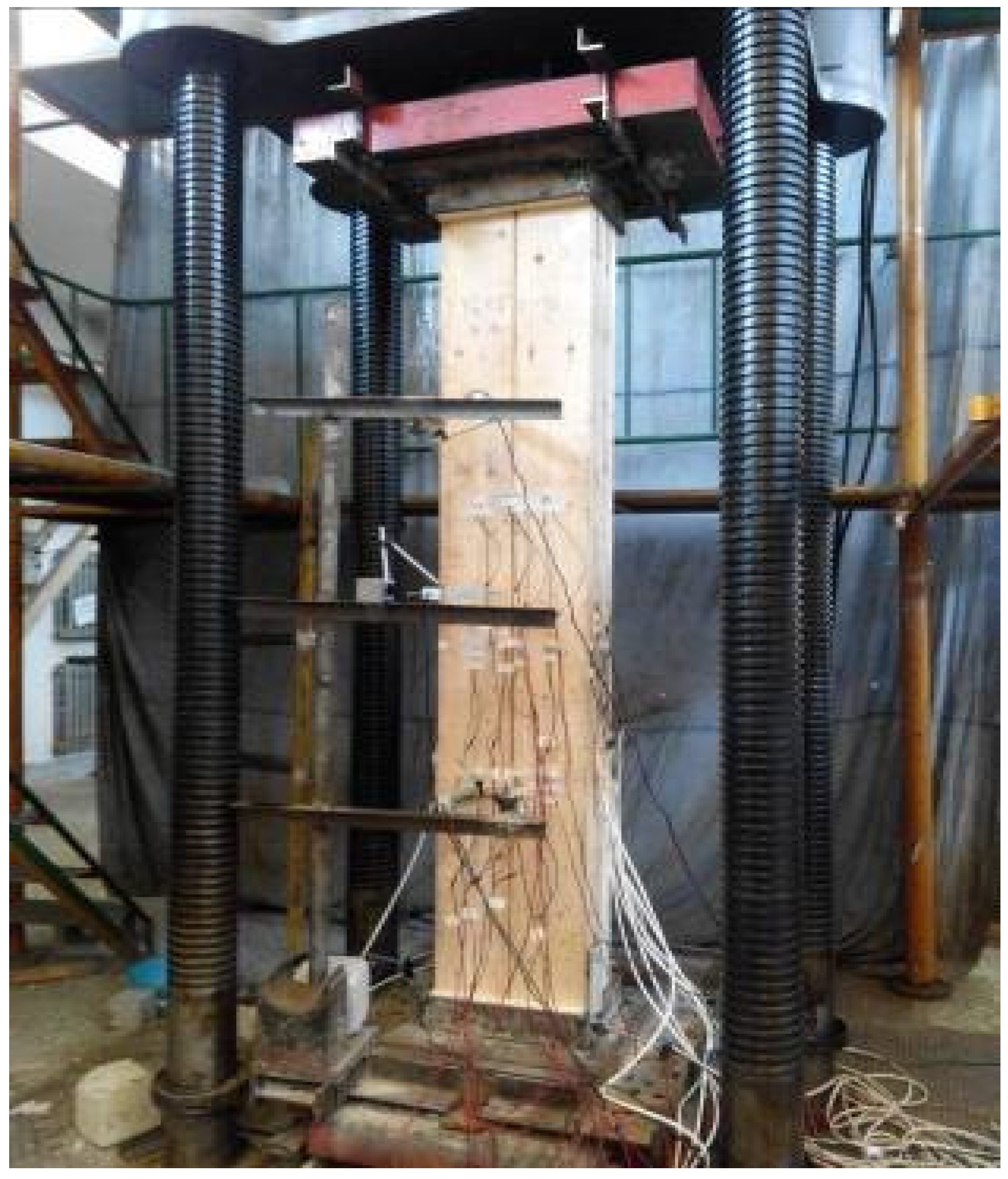
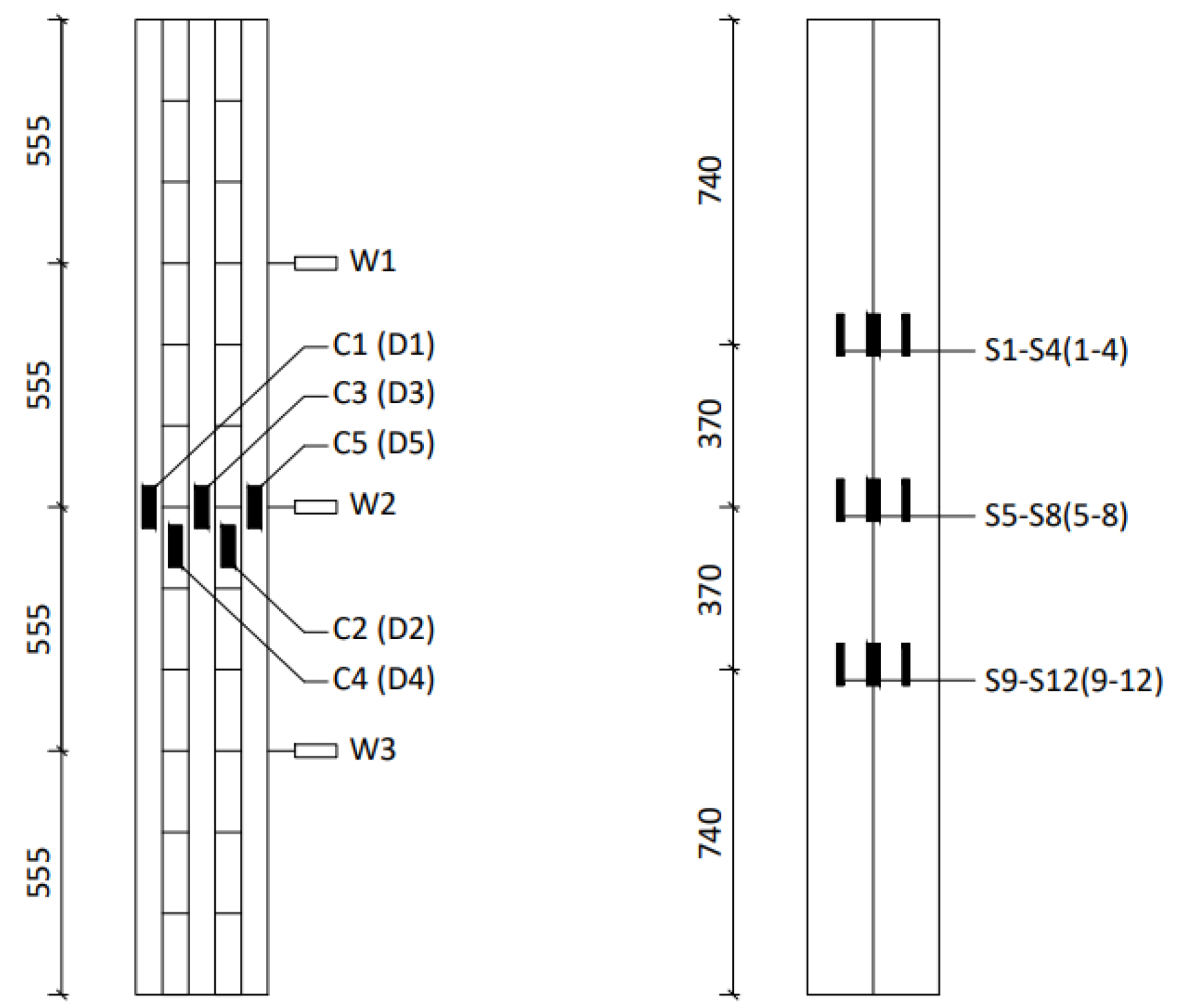
2.2. Test Setup, Iinstrumentation and Experimental Procedures
2.3. Material Properties
3. Experimental Results and Analysis
3.1. General Behavior
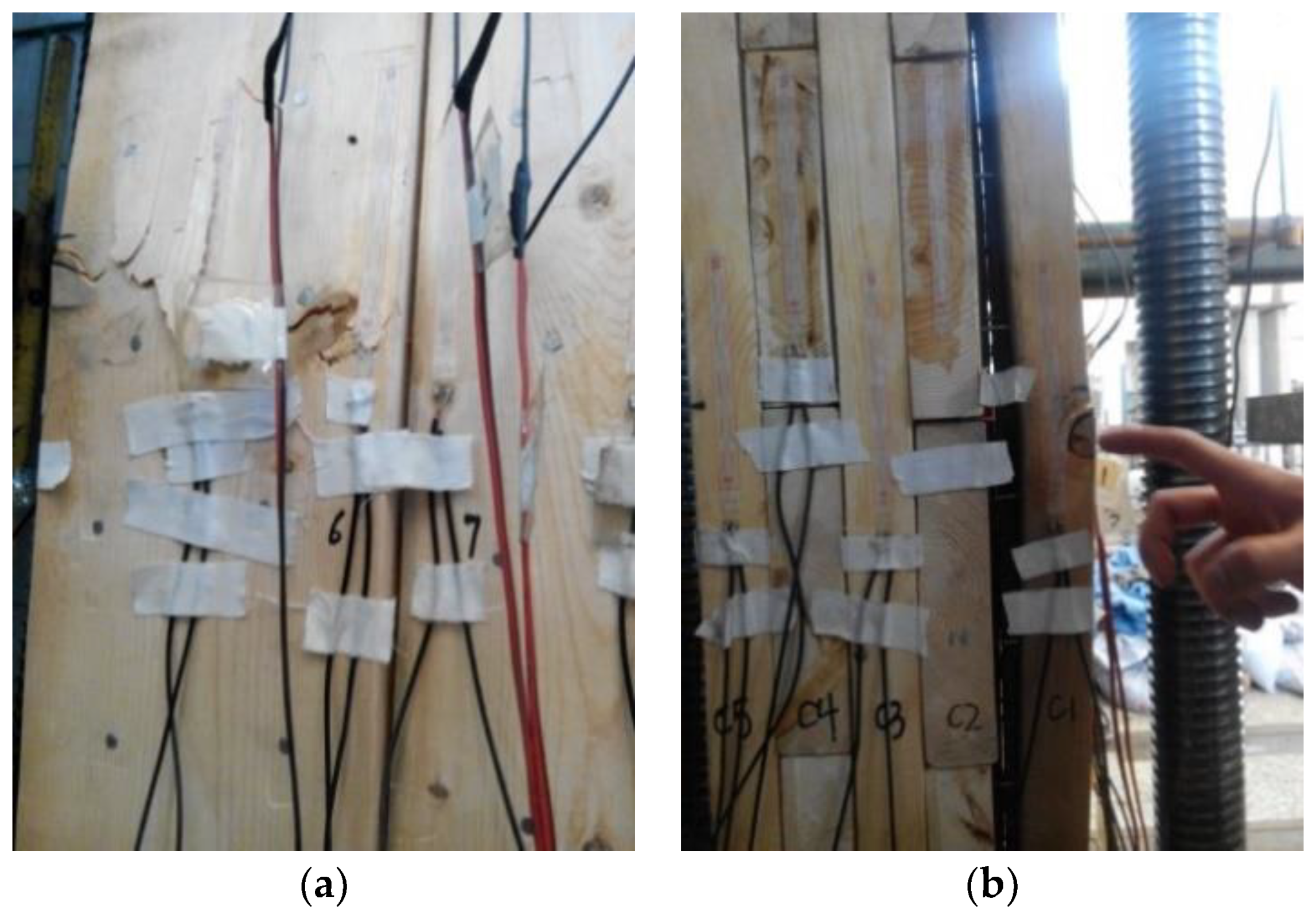
3.2. Failure Mode
3.3. Load-Deflection Curve of NCLT Panels
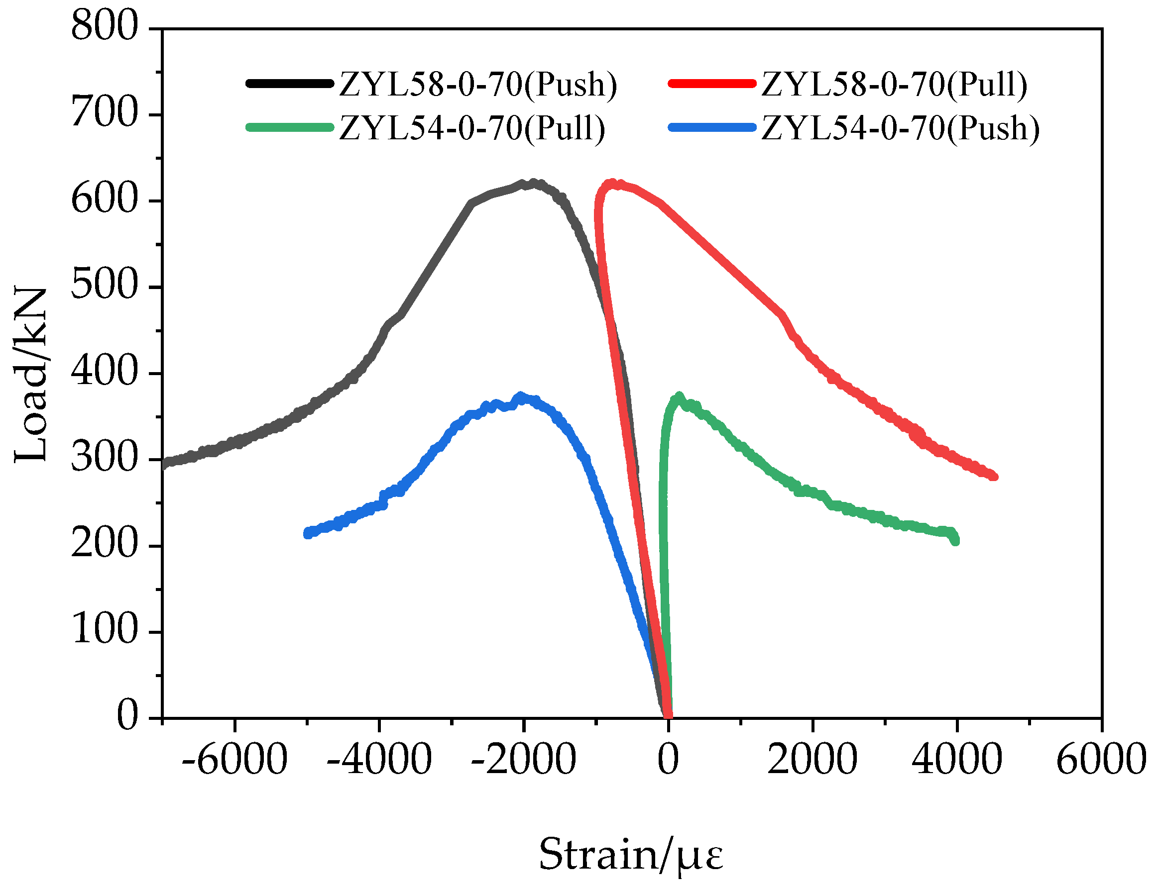
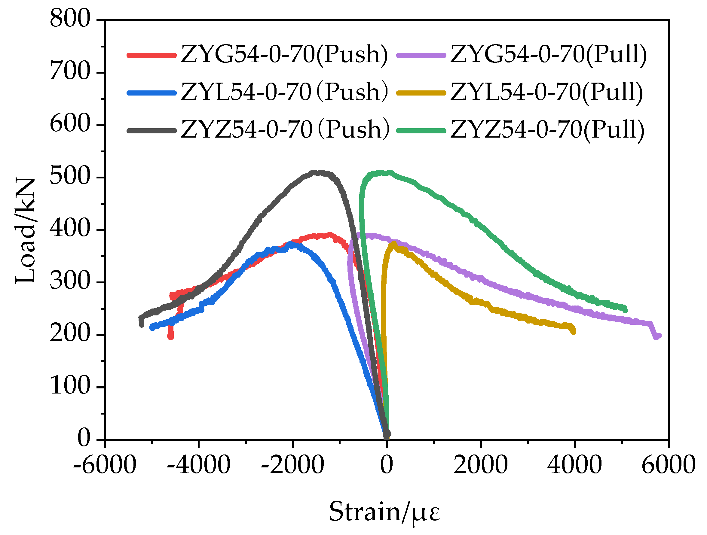
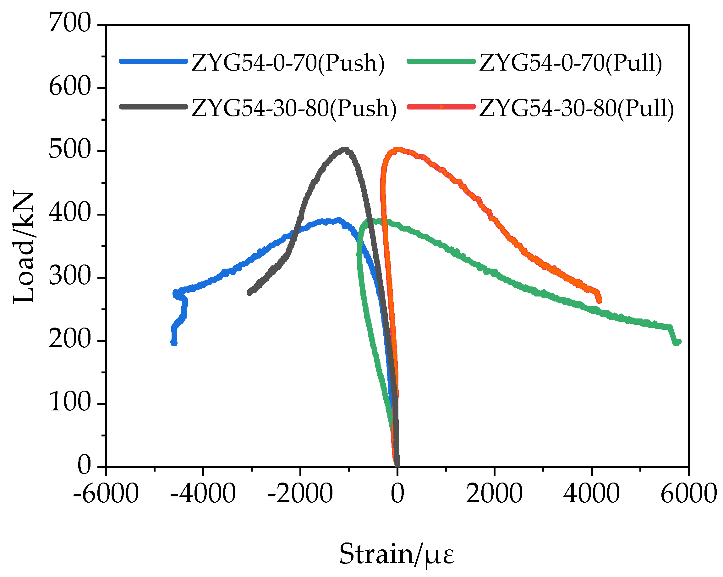
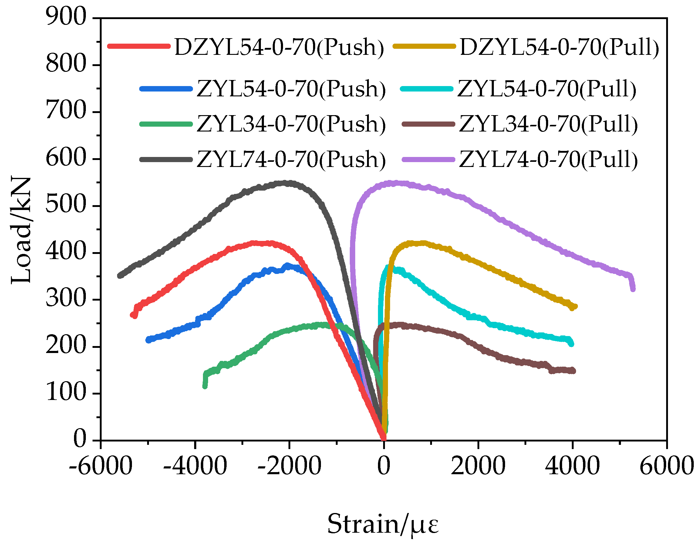
3.4. Load-Strain Curve of NCLT Panels
3.5. Axial-Load Bearing Capacity
4. Conclusions
- Compared with light round nails and thread nails, the specimen connected by tapping screws attained the best compressive performance.
- The increase in the number of nails in the superimposed area greatly reduced both the yield and ultimate displacements of the specimen in the middle span, but had little effect on the rate of increase of tension and compression strain on both sides of the specimen.
- Under drawing action, the pullout anchoring effect of the plate connected by tapping screws was best compared with that using light round nails and thread nails.
- The anti-drawing capability of the entire test specimens can be improved considerably i by increasing the number of nails in the overlapping area and inclining the nails to the wood surface.
- The compressive bearing capacity of the specimen increased with increasing the number of nails in the superimposed area and the tilt angle between the nail and the wood surface. However, the ductility and ability of elastic recovery of the specimens decreased in both cases.
- A certain angle between the nail and wood surface reduced the tensile strain on the tensile side of the specimen and had little effect on the yield and ultimate displacements at the middle of the span.
- The smaller the slenderness ratio, the larger the midspan ultimate displacement, and the slower was the tensile strain increase, the higher the compressive bearing capacity.
- Despite of advantages of NCLT panels, they still have some shortcomings, such as the potential corrosion of nails, that need to be addressed in future concerted research.
Author Contributions
Funding
Institutional Review Board Statement
Informed Consent Statement
Data Availability Statement
Conflicts of Interest
References
- Zarnani, P.; Quenneville, P. New design approach for controlling brittle failure modes of small-dowel-type connections in Cross-laminated Timber (CLT). Constr. Build. Mater. 2015, 100, 172–182. [Google Scholar] [CrossRef]
- Brandner, R. Cross laminated timber (CLT) in compression perpendicular to plane: Testing, properties, design and recommendations for harmonizing design provisions for structural timber products. Eng. Struct. 2018, 171, 944–960. [Google Scholar] [CrossRef]
- Rowell, R.M. Handbook of Wood Chemistry and Wood Composites; CRC Press: Boca Raton, FL, USA, 2005. [Google Scholar]
- Caniato, M.; Marzi, A.; da Silva, S.M.; Gasparella, A. A review of the thermal and acoustic properties of materials for timber building construction. J. Build. Eng. 2021, 43, 103066. [Google Scholar] [CrossRef]
- Dong, Y.; Cui, X.; Yin, X.; Chen, Y.; Guo, H. Assessment of energy saving potential by replacing conventional materials by cross laminated timber (CLT)—A case study of office buildings in China. Appl. Sci. 2019, 9, 858. [Google Scholar] [CrossRef] [Green Version]
- Schmid, J.; König, J.; Just, A. The reduced cross-section method for the design of timber structures exposed to fire—background, limitations and new developments. Struct. Eng. Int. 2012, 22, 514–522. [Google Scholar] [CrossRef]
- Östman, B.; Brandon, D.; Frantzich, H. Fire safety engineering in timber buildings. Fire Saf. J. 2017, 91, 11–20. [Google Scholar] [CrossRef] [Green Version]
- Wang, J.B.; Wei, P.; Gao, Z.; Dai, C. The evaluation of panel bond quality and durability of hem-fir cross-laminated timber (CLT). Eur. J. Wood Wood Prod. 2018, 76, 833–841. [Google Scholar] [CrossRef]
- Hosseinzadeh, S.; Mohebby, B.; Elyasi, M. Bending performances and rolling shear strength of nail-cross-laminated timber. Wood Mater. Sci. Eng. 2020, 1–8. [Google Scholar] [CrossRef]
- Jones, K.; Stegemann, J.; Sykes, J.; Winslow, P. Adoption of unconventional approaches in construction: The case of cross-laminated timber. Constr. Build. Mater. 2016, 125, 690–702. [Google Scholar] [CrossRef] [Green Version]
- Brandner, R.; Flatscher, G.; Ringhofer, A.; Schickhofer, G.; Thiel, A. Cross laminated timber (CLT): Overview and development. Eur. J. Wood Wood Prod. 2016, 74, 331–351. [Google Scholar] [CrossRef]
- Gavric, I.; Fragiacomo, M.; Ceccotti, A. Cyclic behavior of CLT wall systems: Experimental tests and analytical prediction models. J. Struct. Eng. 2015, 141, 04015034. [Google Scholar] [CrossRef]
- Amini, M.O.; van de Lindt, J.W.; Rammer, D.; Pei, S.; Line, P.; Popovski, M. Systematic experimental investigation to support the development of seismic performance factors for cross laminated timber shear wall systems. Eng. Struct. 2018, 172, 392–404. [Google Scholar] [CrossRef]
- Orlowski, K. Failure Modes and Behaviour of Stiffened Engineered Timber Wall Systems under Axial-Loading; Elsevier: Amsterdam, The Netherlands, 2020; pp. 360–369. [Google Scholar]
- Orlowski, K.; Kennedy, D. Design Curves for Stiffened Engineered timber Wall Systems: A Verified Analytical Approach; Elsevier: Amsterdam, The Netherlands, 2020; pp. 1670–1681. [Google Scholar]
- Jiang, Y.; Crocetti, R. CLT-concrete composite floors with notched shear connectors. Constr. Build. Mater. 2019, 195, 127–139. [Google Scholar] [CrossRef]
- Pilon, D.S.; Palermo, A.; Sarti, F.; Salenikovich, A. Benefits of multiple rocking segments for CLT and LVL Pres-Lam wall systems. Soil Dyn. Earthq. Eng. 2019, 117, 234–244. [Google Scholar] [CrossRef]
- Schmidt, E.L.; Riggio, M.; Barbosa, A.R.; Mugabo, I. Environmental response of a CLT floor panel: Lessons for moisture management and monitoring of mass timber buildings. Build. Environ. 2019, 148, 609–622. [Google Scholar] [CrossRef]
- Frese, M.; Blaß, H.J. Statistics of damages to timber structures in Germany. Eng. Struct. 2011, 33, 2969–2977. [Google Scholar] [CrossRef]
- Dietsch, P.; Tannert, T. Assessing the integrity of glued-laminated timber elements. Constr. Build. Mater. 2015, 101, 1259–1270. [Google Scholar] [CrossRef]
- Chen, C.X.; Pierobon, F.; Ganguly, I. Life Cycle Assessment (LCA) of Cross-Laminated Timber (CLT) produced in Western Washington: The role of logistics and wood species mix. Sustainability 2019, 11, 1278. [Google Scholar] [CrossRef] [Green Version]
- Ataei, A.; Chiniforush, A.; Bradford, M.; Valipour, H. Cyclic behaviour of bolt and screw shear connectors in steel-timber composite (STC) beams. J. Constr. Steel Res. 2019, 161, 328–340. [Google Scholar] [CrossRef]
- Gao, Z.; Wang, W.; Zhao, Z.; Guo, M. Novel whey protein-based aqueous polymer-isocyanate adhesive for glulam. J. Appl. Polym. Sci. 2011, 120, 220–225. [Google Scholar] [CrossRef]
- Hasan, H.; Reddy, A.; Tsayjacobs, A. Robotic Fabrication of Nail Laminated Timber, ISARC. In Proceedings of the International Symposium on Automation and Robotics in Construction, University of Alberta, Edmonton, AB, Canada, 21–24 May 2019; pp. 1210–1216. [Google Scholar]
- Krämer, V.; Blass, H. Load Carrying Capacity of Nail-Laminated Timber under Concentrated Loads. In Proceedings of the 34th CIB W18 Meeting, Venice, Italy, 22–24 August 2001. [Google Scholar]
- Bohnhoff, D.R. Bending Properties of Reinforced and Unreinforced Spliced Nail-Laminated Posts; US Department of Agriculture, Forest Service, Forest Products Laboratory: Madison, WI, USA, 1991; Volume 503. [Google Scholar]
- Derikvand, M.; Jiao, H.; Kotlarewski, N.; Lee, M.; Chan, A.; Nolan, G. Bending performance of nail-laminated timber constructed of fast-grown plantation eucalypt. Eur. J. Wood Wood Prod. 2019, 77, 421–437. [Google Scholar] [CrossRef]
- Herberg, E.L. Flexural Performance of Nail-Laminated Timber Crane Mats; University of Minnesota: Minneapolis, MN, USA, 2018. [Google Scholar]
- Hong, K.E.M. Structural Performance of Nail-Laminated Timber-Concrete Composite Floors; University of British Columbi: Vancouver, BC, Canada, 2017. [Google Scholar]
- Zhang, Y.; Nehdi, M.L.; Gao, X.; Zhang, L.V. Flexural Performance of Novel Nail-Cross-Laminated Timber Composite Panels. Appl. Sci. 2020, 10, 5983. [Google Scholar] [CrossRef]


| a | Rift Grain | Band | |||
|---|---|---|---|---|---|
| Mid-Range | Terminal Distance | Mid-Range S2 | Margin | ||
| S1 | S0 | Homogeneous Column | Staggered or Slanted Column | S3 | |
| a ≥ 10 d | 15 d | 15 d | 4 d | 3 d | 4 d |
| 10 d > a > 4 d | Fetch insertion value | ||||
| a = 4 d | 25 d | ||||
| Specimen Number | Nail Type | Number of Plies | Nail Number | Nail Angle | Nail Length /mm | Nail Diameter/mm | Sectional Dimension/mm2 | Specimen Height/mm |
|---|---|---|---|---|---|---|---|---|
| ZYG54-0-70 | Round nail | 5 | 4 | 0 | 70 | 3.5 | 370 × 190 | 2220 |
| ZYL54-0-70 | Screw nail | 5 | 4 | 0 | 70 | 2 | 370 × 190 | 2220 |
| ZYZ54-0-70 | Self-tapping screw | 5 | 4 | 0 | 70 | 3 | 370 × 190 | 2220 |
| ZYL34-0-70 | Screw nail | 5 | 4 | 0 | 70 | 2 | 370 × 114 | 2220 |
| ZYL74-0-70 | Screw nail | 5 | 4 | 0 | 70 | 2 | 370 × 266 | 2220 |
| ZYL58-0-70 | Screw nail | 5 | 8 | 0 | 70 | 2 | 370 × 190 | 2220 |
| ZYG54-30-80 | Round nail | 5 | 4 | 30 | 80 | 3.5 | 370 × 190 | 2220 |
| DZYL54-0-70 | Screw nail | 5 | 4 | 0 | 70 | 2 | 370 × 190 | 1800 |
| Varieties of Trees | Bending Strength/MPa | Along-Line Compression Strength/MPa | Transverse Compression Strength/MPa | Density/kg/m3 | Rate of Water Content |
|---|---|---|---|---|---|
| Spruce | 69.5 | 37.8 | 4.1 | 430 | 12% |
| Pine | 68.9 | 40.8 | 3.6 | 445 | 12% |
| fir | 69.1 | 38.9 | 3.8 | 440 | 12% |
| Specimen Group | Nail Type | Number of Nails | Nail Angle | Ultimate Pull-Out Load/kN |
|---|---|---|---|---|
| LG4-0 | Round nail | 4 | 0° | 0.37 |
| LG4-30 | Round nail | 4 | 30° | 1.11 |
| LL4-0 | Screw nail | 4 | 0° | 1.40 |
| LL8-0 | Screw nail | 8 | 0° | 3.29 |
| LZ4-0 | Self-tapping screw | 4 | 0° | 4.09 |
| Specimen Number | Destruction Form | Splitting Length/mm | Flexure Direction |
|---|---|---|---|
| ZYG54-0-70 | Bending of one of the vertical solid wood laminate layers on the drawing side. | 1 | |
| ZYL54-0-70 | Split at medial margin. Lateral edge splitting. One of the vertical, solid wood laminate layers bent and bent on the drawing side. | 400 100 | 2 |
| ZYZ54-0-70 | A split at the inside edge of one of the vertical solid laminate layers. | 180 | 2 |
| ZYL34-0-70 | One of the vertical, solid wood laminate layers bent and bent on the drawing side. Split at medial margin. Lateral edge splitting. Left vertical striped solid wood laminate splitting. | 420 180 240 | 3 |
| ZYL74-0-70 | 3 | ||
| ZYL58-0-70 | One of the vertical, solid wood laminate layers bent and bent on the drawing side. Split at medial margin. Lateral edge splitting. Split on the inside edge of another vertical solid board layer on the pull side. Lateral edge splitting. | 80 210 420 300 | 3 |
| ZYG54-30-80 | Splitting of one of the vertical solid wood slabs on the compressed side | 400 | 2 |
| DZYL54-0-70 | The bending of one of the vertical solid wood laminate layers on the drawing side. | 1 |
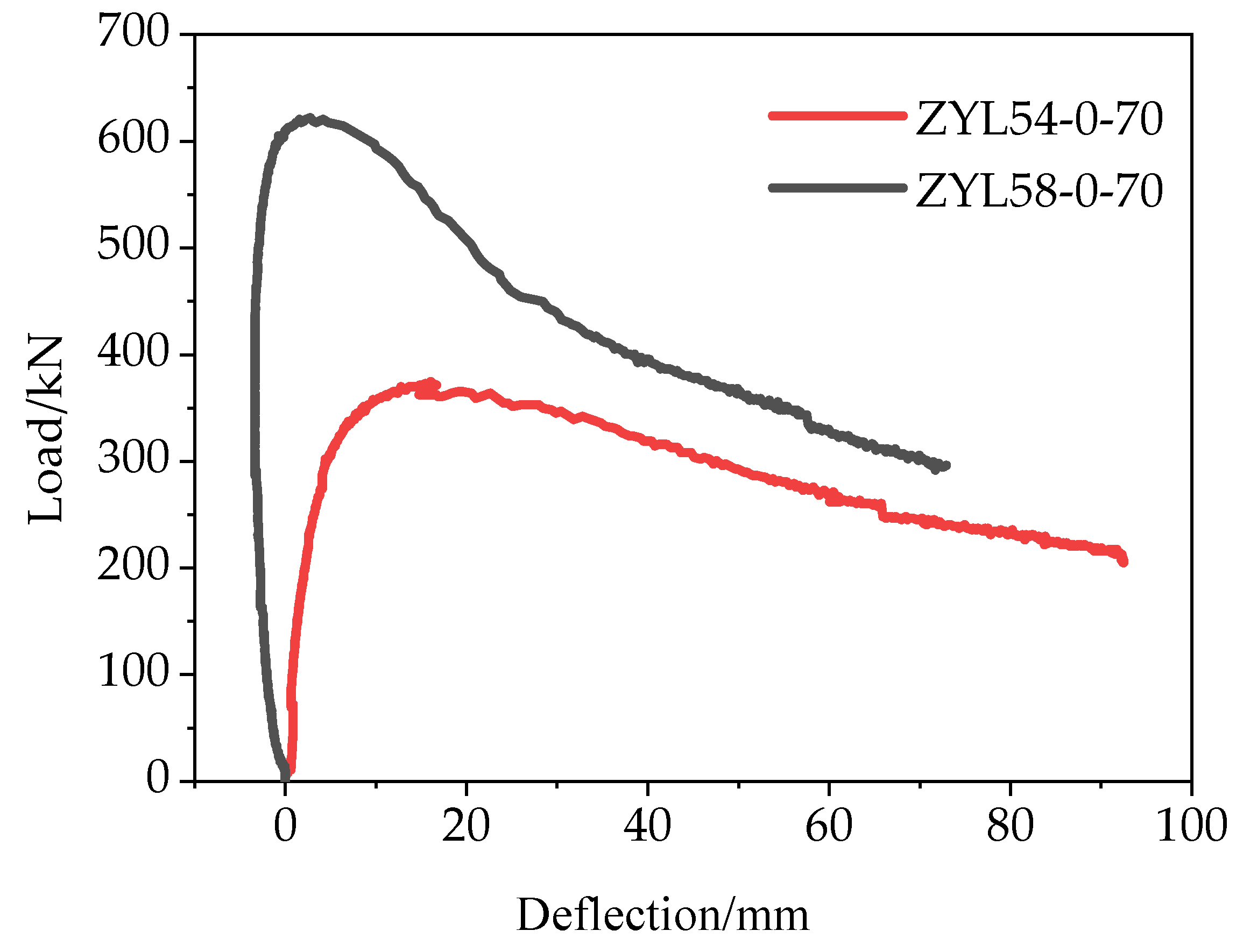
| Number | Number of Nails | Pu/kN | Δm (mm) | Δy (mm) |
|---|---|---|---|---|
| ZYL54-0-70 | 4 | 374.5 | 16.06 | 4.34 |
| ZYL58-0-70 | 8 | 622.1 | 2.77 | 2.99 |
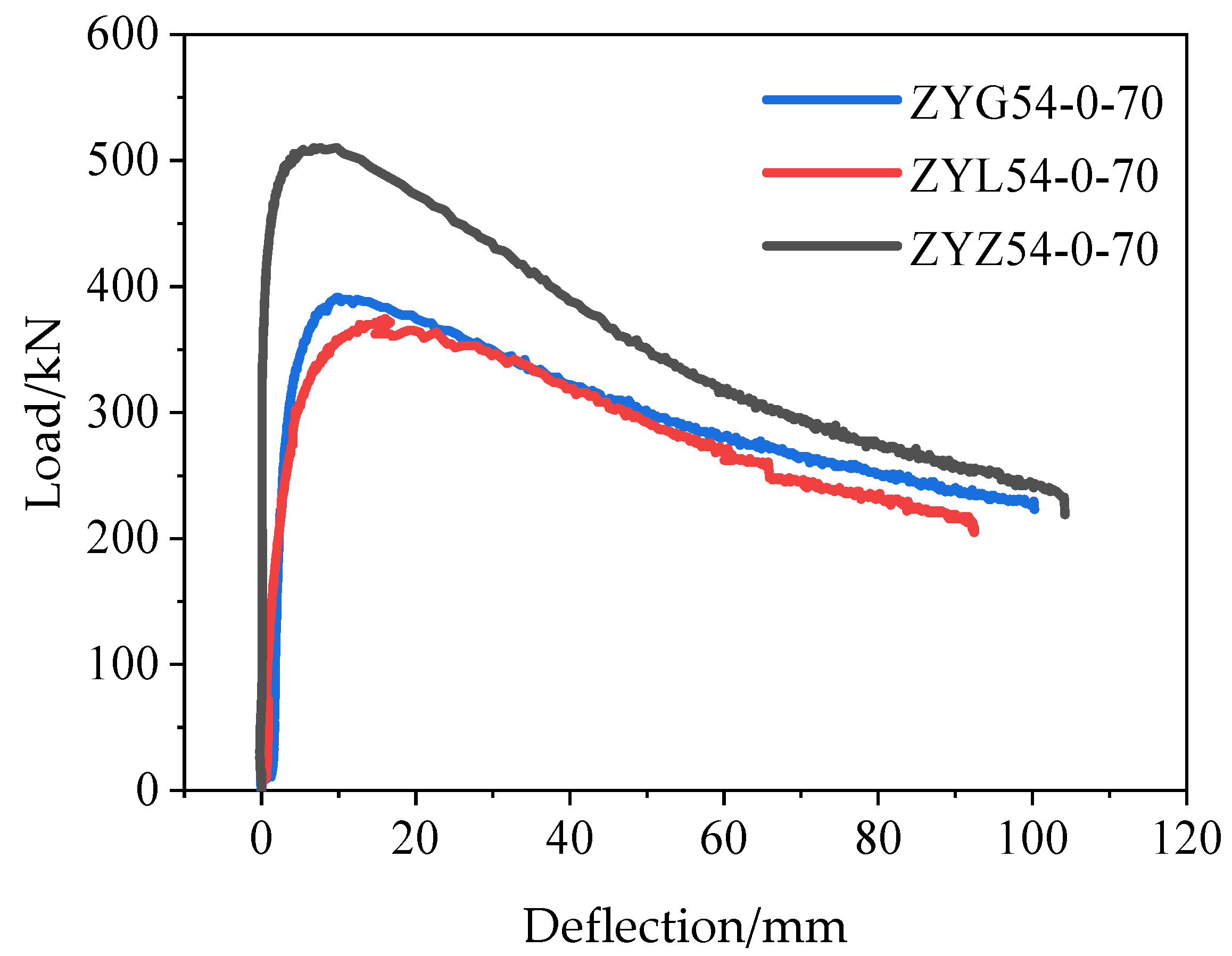
| Number | Type of Nail | Pu/kN | Δm (mm) | Δy (mm) |
|---|---|---|---|---|
| ZYG54-0-70 | Round nail | 391.2 | 10.00 | 3.82 |
| ZYL54-0-70 | Screw nail | 374.5 | 16.06 | 4.34 |
| ZYZ54-0-70 | Self-tapping screw | 530.1 | 9.77 | 0.56 |
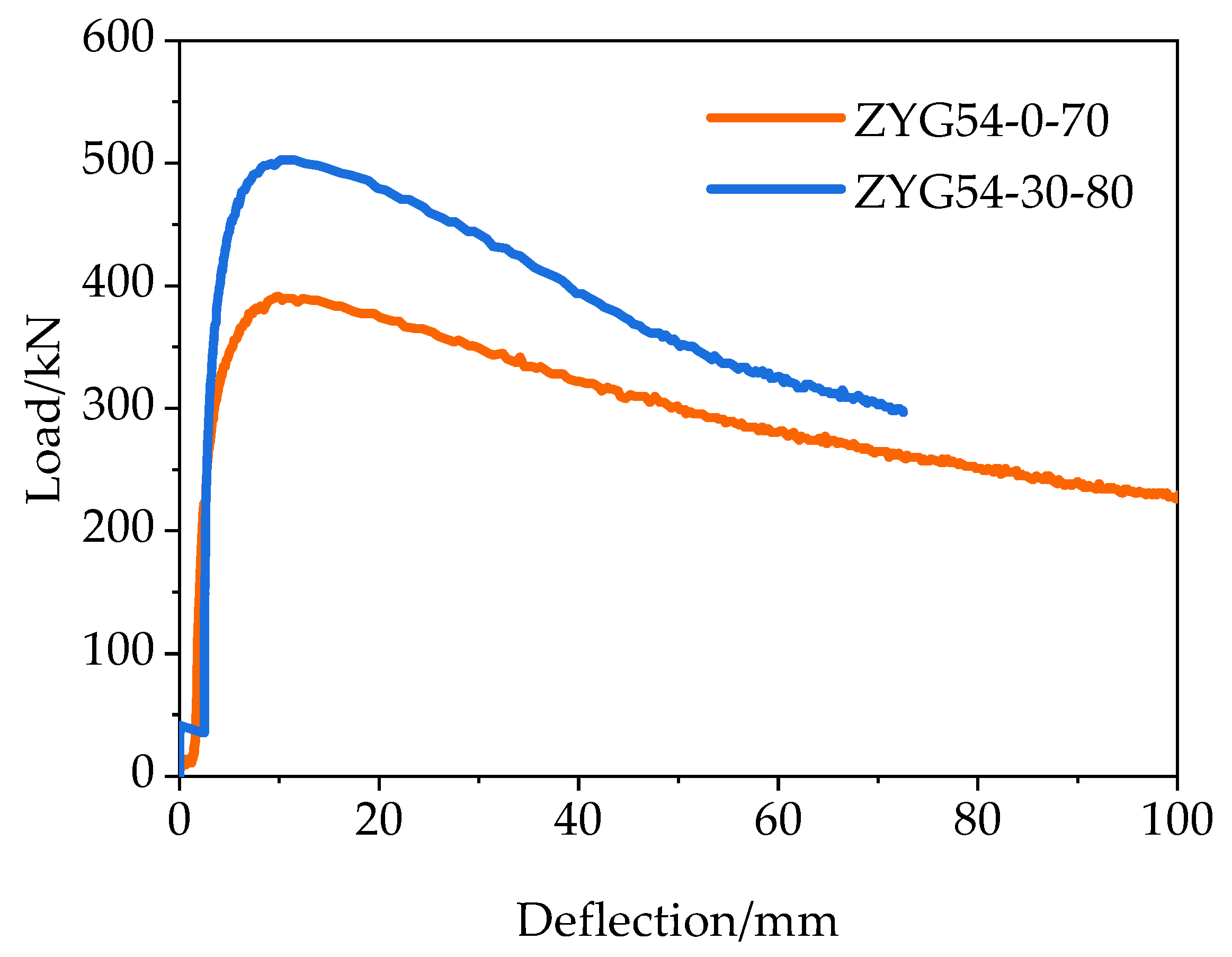
| Number | Nail Angle | Pu/kN | Δm (mm) | Δy (mm) |
|---|---|---|---|---|
| ZYG54-0-70 | 0 | 391.2 | 10.00 | 3.82 |
| ZYG58-30-80 | 30 | 502.8 | 10.15 | 4.12 |
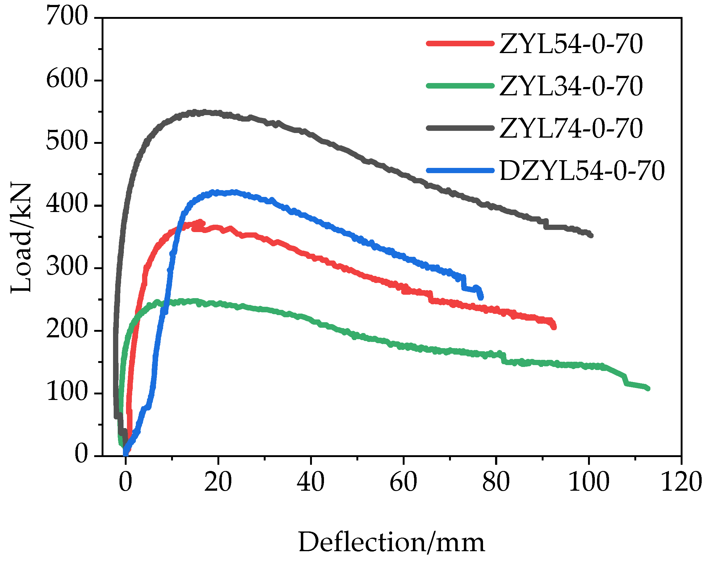
| Number | λ | Pu/kN | Δm (mm) | Δy (mm) |
|---|---|---|---|---|
| ZYL34-0-70 | 67.11 | 247.7 | 11.64 | 0.85 |
| ZYL54-0-70 | 40.47 | 374.5 | 16.06 | 4.34 |
| DZYL54-0-70 | 32.80 | 421.8 | 18.73 | 10.75 |
| ZYL74-0-70 | 28.71 | 567.9 | 17.01 | 1.27 |
| Test Specimens No. | Trial Value F/kN | N1/kN | N2/kN | N3/kN | N4/kN | N5/kN | N6/kN | N7/kN | N8/kN |
|---|---|---|---|---|---|---|---|---|---|
| ZYL34-0-70 | 247.7 | 203.1 | 172.93 | 105.02 | 138.16 | 266.02 | 278.36 | 182.04 | 234.62 |
| ZYL54-0-70 | 374.5 | 503.8 | 392.13 | 363.64 | 473.47 | 542.94 | 528.06 | 514.83 | 558.60 |
| DZYL54-0-70 | 421.8 | 557.2 | 431.29 | 435.30 | 530.04 | 577.40 | 558.05 | 559.52 | 586.88 |
| ZYL74-0-70 | 567.9 | 819.2 | 632.15 | 734.43 | 809.24 | 767.16 | 742.26 | 759.74 | 774.51 |
| ZYG54-0-70 | 391.2 | 503.8 | 392.13 | 363.64 | 473.47 | 542.94 | 528.06 | 514.83 | 558.60 |
| ZYZ54-0-70 | 530.1 | 503.8 | 392.13 | 363.64 | 473.47 | 542.94 | 528.06 | 514.83 | 558.60 |
| ZYL58-0-70 | 622.1 | 503.8 | 392.13 | 363.64 | 473.47 | 542.94 | 528.06 | 514.83 | 558.60 |
| ZYG54-30-80 | 502.8 | 503.8 | 392.13 | 363.64 | 473.47 | 542.94 | 528.06 | 514.83 | 558.60 |
| Test Specimens No. | F/N1 | F/N2 | F/N3 | F/N4 | F/N5 | F/N6 | F/N7 | F/N8 |
|---|---|---|---|---|---|---|---|---|
| ZYL34-0-70 | 1.22 | 1.43 | 2.36 | 1.79 | 0.93 | 0.89 | 1.36 | 1.06 |
| ZYL54-0-70 | 0.74 | 0.96 | 1.03 | 0.79 | 0.69 | 0.71 | 0.73 | 0.67 |
| DZYL54-0-70 | 0.76 | 0.98 | 0.97 | 0.80 | 0.73 | 0.76 | 0.75 | 0.72 |
| ZYL74-0-70 | 0.69 | 0.92 | 0.77 | 0.70 | 0.74 | 0.77 | 0.75 | 0.73 |
| ZYG54-0-70 | 0.78 | 1.00 | 1.08 | 0.83 | 0.72 | 0.74 | 0.76 | 0.70 |
| ZYZ54-0-70 | 1.05 | 1.35 | 1.46 | 1.12 | 0.98 | 1.00 | 1.03 | 0.95 |
| ZYL58-0-70 | 1.23 | 1.59 | 1.71 | 1.31 | 1.15 | 1.18 | 1.21 | 1.11 |
| ZYG54-30-80 | 1.00 | 1.28 | 1.38 | 1.06 | 0.93 | 0.95 | 0.98 | 0.90 |
Publisher’s Note: MDPI stays neutral with regard to jurisdictional claims in published maps and institutional affiliations. |
© 2021 by the authors. Licensee MDPI, Basel, Switzerland. This article is an open access article distributed under the terms and conditions of the Creative Commons Attribution (CC BY) license (https://creativecommons.org/licenses/by/4.0/).
Share and Cite
Nehdi, M.L.; Zhang, Y.; Gao, X.; Zhang, L.V.; Suleiman, A.R. Experimental Investigation on Axial Compression of Resilient Nail-Cross-Laminated Timber Panels. Sustainability 2021, 13, 11257. https://0-doi-org.brum.beds.ac.uk/10.3390/su132011257
Nehdi ML, Zhang Y, Gao X, Zhang LV, Suleiman AR. Experimental Investigation on Axial Compression of Resilient Nail-Cross-Laminated Timber Panels. Sustainability. 2021; 13(20):11257. https://0-doi-org.brum.beds.ac.uk/10.3390/su132011257
Chicago/Turabian StyleNehdi, Moncef L., Yannian Zhang, Xiaohan Gao, Lei V. Zhang, and Ahmed R. Suleiman. 2021. "Experimental Investigation on Axial Compression of Resilient Nail-Cross-Laminated Timber Panels" Sustainability 13, no. 20: 11257. https://0-doi-org.brum.beds.ac.uk/10.3390/su132011257