Article

Embodied Energy and Cost Assessments of a Concentrating Photovoltaic Module

by
Daria Freier Raine
1,*,
Firdaus Muhammad-Sukki
2,*,
Roberto Ramirez-Iniguez
1,
Jorge Alfredo Ardila-Rey
3,
Tahseen Jafry
1 and
Carlos Gamio
1
1
School of Computing, Engineering and Built Environment, Glasgow Caledonian University, 70 Cowcaddens Road, Glasgow G4 0BA, UK
2
School of Engineering & the Built Environment, Edinburgh Napier University, Merchiston Campus, 10 Colinton Road, Edinburgh EH10 5DT, UK
3
Department of Electrical Engineering, Universidad Técnica Federico Santa María, Santiago 8940000, Chile
*
Authors to whom correspondence should be addressed.
Sustainability 2021, 13(24), 13916; https://0-doi-org.brum.beds.ac.uk/10.3390/su132413916
Submission received: 11 August 2021 / Revised: 9 December 2021 / Accepted: 14 December 2021 / Published: 16 December 2021
(This article belongs to the Special Issue Renewable Energy Technologies and Environmental Impact Assessment)

Abstract

:
This paper focuses on the embodied energy and cost assessments of a static concentrating photovoltaic (CPV) module in comparison to the flat photovoltaic (PV) module. The CPV module employs a specific concentrator design from the Genetically Optimised Circular Rotational Square Hyperboloid (GOCRSH) concentrators, labelled as GOCRSH_A. Firstly, it discussed previous research on life cycle analyses for PV and CPV modules. Next, it compared the energy embodied in the materials of the GOCRSH_A module to the energy embodied in the materials of a flat PV module of the same electrical output. Lastly, a comparison in terms of cost is presented between the analysed GOCRSH_A module and the flat PV module. It was found that the GOCRSH_A module showed a reduction in embodied energy of 17% which indicates a reduction in embodied carbon. In terms of cost, the costs for the GOCRSH_A module were calculated to be 1.71 times higher than the flat PV module of the same electrical output. It is concluded that a trade-off is required between the embodied energy and cost impacts in order to bring this CPV technology into the market.

1. Introduction

During the United Nations Climate Change Conference in 2015, 195 of the member states agreed that climate change will be the main threat to humanity for years to come [1]. Our heavy reliance on fossil fuels for energy generation and our excessive energy consumption in the Global North are the core of this problem. In order to keep global warming within 1.5 °C above pre-industrial levels, the highlights of the outstanding Intergovernmental Panel on Climate Change (IPCC)’s 2018 report [2,3] show that whilst remaining fossil fuels must be left underground, it is crucial to reduce global energy consumption. This does not only apply to industrialised countries but also to countries that are at an earlier stage of development. Furthermore, the pollution of air, water and soil associated with energy generation has already caused humanitarian and environmental crises in fast developing countries such as China [4].
Whilst the impact of climate change is universal, people living in poverty are more vulnerable to extreme weather conditions such as floods, landslides or draughts and these are expected to become more frequent and more severe with climate change [5]. Those who have contributed the least to global warming are most severely affected by its consequences; this inequality is referred to as climate injustice [6,7]. Recognising and addressing this inequality enables us to achieve climate justice.
Our ability to adapt and build resilience to climate change depends on various factors such as financial and social security, access to education and to communication systems. Increased access to electricity and thus improved access to education and telecommunication helps in coping with emergencies, adaptation to new locations and provides the ability to mitigate risk, thus increasing the resilience of poor and vulnerable communities to climate change [8].
Portable off-grid solar chargers have been shown to enable these amenities [9] and to contribute to better resilience of the poorest and most vulnerable to climate change [8]. In Myanmar, for instance, people took these solar systems with them amongst the few goods when they were displaced. Although the displacement in Myanmar is not in a direct context of climate change, it demonstrates the value of solar technology to displaced households and shows the importance of solar systems being portable [8]. Furthermore, small solar systems have been used as the first emergency response after catastrophic events to cover basic needs [8].
Whilst having access to electricity can help one adapt to climate change, the greenhouse gas (GHG) emissions from energy provision need to be further reduced. PV has a smaller impact on the environment than fossil-based energy systems, yet its impact increases with scale. SolarAid alone has sold more than 1.7 million solar lights, which do, however, have reported use of only 3–5 years [10] with limited possibilities for recycling. The production of the solar PV modules is energy intensive, leading to high GHG emissions, and this process is viewed as being the highest contributor to human- and eco-toxicity potential when developing the solar charger. As has been summarised by Lamnatou and Chemisana [11], incorporating solar concentrators in a PV module reduces the energy required for manufacturing of the PV module, lowers the associated GHG emissions and has the advantage of the ease of recycling of the constituent materials and reduced use of toxic products. Reducing the environmental impact of portable solar energy systems is necessary to reduce carbon emissions and hence adds to addressing climate injustice.
This paper aims at assessing the embodied energy and cost impacts of a static concentrating photovoltaic (CPV) module relative to a flat photovoltaic (PV) module. The CPV module employs a specific concentrator design from the Genetically Optimised Circular Rotational Square Hyperboloid (GOCRSH) concentrators proposed by Freier Raine et al. [12]. A “cradle-to-grave” analysis of the GOCRSH_A module is out of scope for this paper, due to the limited time allocated to this project. The aim of this paper therefore is not to draw a comparison between systems manufactured and used in a specific location, but rather to give an indication on the embodied energy of the materials, since the embodied carbon and impact factors have been shown to be driven by the electricity and steam generation for energy-intensive processes. There is also a scope for cost analysis in the second part of the paper to compare both the CPV and the flat non-concentrating PV modules. This is the first time these analyses have been carried out for GOCRSH concentrators.
Section 1 is the introduction. Section 2 looks at the methodology, covering the basic terminology of the life cycle assessment and the assessment method. Section 3 outlines the embodied energy analysis follows by Section 4, which analyses the cost of implementing the CPV. Finally, Section 5 concludes the paper.

2. Methodology

2.1. Terminology in Sustainability Analyses

The environmental impact of a product is commonly identified through a life cycle analysis (LCA). An LCA is a structured and comprehensive method of quantifying material and energy flows and the associated emissions during the life cycle of a product [13]. It is often referred to as a “cradle to grave” analysis, which includes materials and processes from raw material extraction through to the production, transportation, use and end-of-life of the product [13]. Furthermore, it encompasses the impact on people involved in all product life stages and on the environment [14].
LCA has specific terminology including embodied energy (EE), embodied carbon (EC) and several impact categories. EE is the energy required for processing and supplying the material. EC is directly associated with the EE of the material and also includes GHG emissions during the life cycle of the product, which can be represented as a CO2 equivalent. A measure of the environmental performance of the product is its energy payback time (EPBT), which is the time required by the system to generate the amount of energy required during its production. Analogically, the definition for the greenhouse gas payback time (GPBT) is the amount of time a system requires to compensate for the GHG emissions that were released during its production.
The impact on the environment and human health is assessed and categorised in terms of global warming potential (GWP), acidification potential (AP), eutrophication potential (EP), human toxicity potential (HTP), photochemical ozone creation potential (POCP) and ozone layer depletion potential (ODP) [15]. According to the IPCC, the GWP refers to the release of gases that contribute to global warming [16]. AP denotes the amount of air pollutants, such as sulphur dioxide and nitrogen oxide, released during electricity production and fuel combustion, which can lead to the acidification of soils and water when transformed into acids [15,17]. Čuček et al. [18] define EP as the contribution to the increase in nitrogen and phosphorus in the rivers or lakes leading to the rapid growth of water plants. Overstimulation of the growth of water plants on the surface causes a reduction of sunlight in the deeper waters, reducing photosynthesis and leading to the suffocation of fish due to the lack of oxygen [17]. Singh et al. [19] indicated that HTP relates to the emissions of substances, which due to their chemical or physical properties can cause damage to a person’s health over a period of time. It includes the point source of the emissions, its behaviour and the potential to spread in the environment [17]. ODP refers to the emissions of chlorofluorocarbons and nitrogen oxides, which lead to the depletion of the ozone layer and thus to an increased amount of short-wave UV radiation, which harms animal and vegetational health [17,20]. Ozone at the ground level and in the troposphere, however, can harm the ecosystems and be toxic to humans. It is created in a reaction between nitrogen oxides and hydrocarbons under solar radiation. The main contributor to the POCP is attributed to electricity production and fuel combustion. Thus, the production process of PV cells contributes the most to the POCP.

2.2. Low Concentration Photovoltaic (LCPV) Sustainability Analyses in Literature

To date, only a limited number of LCA studies on concentrated photovoltaic (CPV) systems can be found. Lamnatou and Chemisana [11] have conducted a comparative analysis of all CPV LCA studies up to 2016 and concluded that the majority of CPV LCA studies were on high-concentration PV systems. For low-concentration PV (LCPV), only a few LCA studies have been published, which are referred to in the following paragraphs.
Lamnatou et al. [21,22] carried out two LCA studies for the truncated dielectric asymmetric compound parabolic concentrator (Di-ACPC) module, which was proposed by Sarmah [23] for building integration. The Di-ACPC was made of polyurethane, had a geometric concentration ratio of 2.8× and was assumed to be used with monocrystalline (mono-c-Si) cells. The first study [21] examined the influence of the user’s location on the EPBT and showed an overall reduction in EBPT by 1.2 years compared to a flat PV module. From this analysis, PV cells were found to have the highest contribution to the embodied energy and the embodied carbon followed by the dielectric concentrators.
Lamnatou et al. [
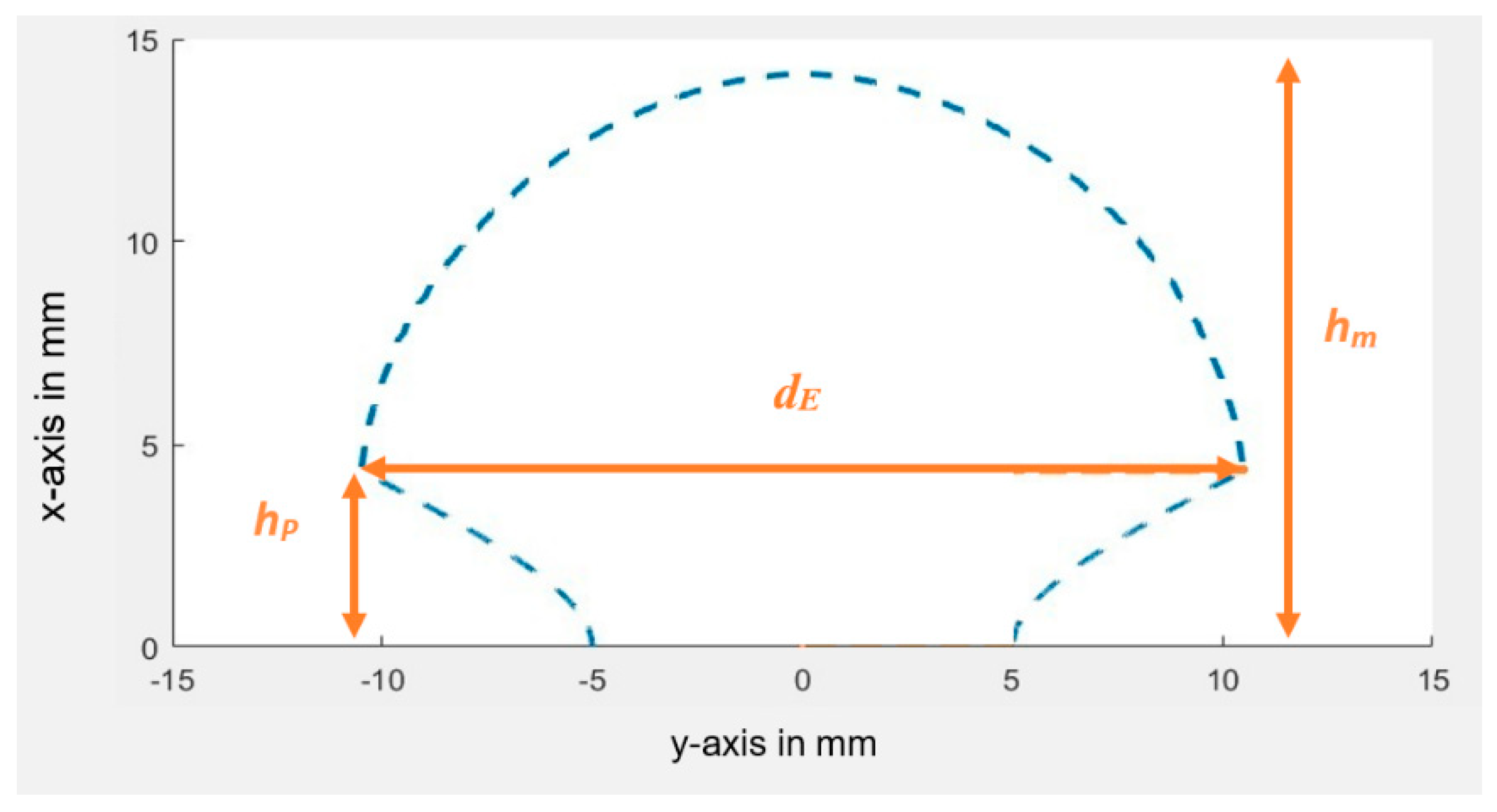
22] then completed a more advanced study of the Di-ACPC module using different life cycle impact assessment methods and environmental indicators. From the second study, PV cells were found to have the highest contribution to climate change and the highest impact on ecosystems, human health and toxicity. The concentrator, on the other hand, had the highest impact on resource depletion. The amount of resources used for the concentrator production depends on the gain-to-volume relation of the concentrator. The Di-ACPC-55 is a less compact design than the GOCRSH_A, with an optical concentration ratio of around 2.3×, while the optical concentration ratio of the Di-ACPC-55 at normal incidence is 19% smaller compared to the optical concentration ratio of the GOCRSH_A and its volume for a 100 mm2 solar cell is smaller by 4% (Di-ACPC-55 volume for a 100 mm2 solar cell is estimated as 2633 mm3). Furthermore, the GOCRSH_A has a larger field of view and thus enables electricity generation for more hours. Larger sustainability benefits can therefore be assumed from the GOCRSH design compared to the Di-ACPC design.
Lamnatou et al. [24] conducted a further LCA for the 3D crossed compound parabolic concentrator (CCPC) proposed by Sellami [25]. The 3D CCPC was made from polyurethane, assumed to be used with mono-c-Si cells, had a geometric concentration ratio of 3.6× and was analysed for building integration in seven different cities. Using several LCA methodologies, similar results as the Di-ACPC LCA were obtained, with the PV cells showing the strongest impact on human health and ecosystems whilst the 3D CCPC module contributed the most to resource depletion. Since the gain-to-volume relation of the GOCRSH_A is higher than of the 3D CCPC within the angles of incidence of ±40°, the GOCRSH is expected to further reduce the impact on human health and ecosystems and to use fewer resources. The optical concentration ratio of the GOCRSH_A within the angles of incidence of ±40° is higher by 9.3% while its volume is smaller by 32% compared to the 3D CCPC.
A further study was undertaken by De Feo et al. [26] for a reflective V-trough concentration system installed in Italy. With a geometric concentration ratio of 2.0× and integration with poly-ci-Si cells, the analysis concluded that an environmental impact reduction in CO2 equivalent of around 17% can be achieved.
Zawadzki et al. [27] carried out an LCA on a rotationally asymmetrical compound parabolic concentrator (RACPC) that has a geometrical concentration ratio of 2.67× and integrated with mono-c-Si cells. They found that 67% of the total embodied energy is put towards the manufacture of PV material for a conventional PV module whereas for the RACPC-PV module, 50% of all total embodied energy is used in the manufacture of all concentrators made from Poly(methyl methacrylate) (PMMA). They concluded that the RACPC-PV module has a reduction of 11.76% of the embodied energy material manufactured when compared to a conventional solar photovoltaic (PV) module.
An LCA for the asymmetric compound parabolic concentrator (a-CPC) system made of PMMA, with a power ratio of 1.74× and integration with mono-c-Si cells was carried out by Li et al. [17]. The authors identified that PV cells had the main contribution to the AP, GWP, EP and HTP followed by the production of the a-CPC device. The production of the mono-c-Si solar cells and the transformation from MMA to PMMA were identified as the most energy-intensive process steps. Therefore, a reduction in PV and PMMA materials is crucial to minimise the environmental impact of the CPV system.
Overall, the AP, EP and HTP in CPV systems are associated with the electricity generation required for the production of the module components. The AP impact increases with the amount of coal-based electricity in the electricity mix since the combustion of coal leads to the release of nitrogen oxide. The EP influence is mainly due to the release of phosphate and nitrite acid during electricity and steam production. From the module assembly process, the polyethylene terephthalate (PET), polyvinyl fluoride (PVF), ethylene-vinyl acetate (EVA) foils and the glue, as well as the aluminium, were identified as the main contributors [17]. Furthermore, the HTP effect is mainly due to heavy metals and emissions released to the air and clean water during the production of electricity, steam and materials [17]. In contrast to the indicators discussed above, the main contributors to the ODP are primarily attributed to the fabrication of primary aluminium for the module frame [17]. From the LCPV LCA analyses carried out in the literature, it can be concluded that the substitution of the PV material with dielectric concentrators reduces the impact of the modules on the environment mainly by reducing the energy embodied in the module materials [17]. In the following Section 3, a comparison is drawn between the energy embodied in the materials of the GOCRSH_A module and a flat PV module.

2.3. Assessed System: Characteristics of the GOCRSH_A and Flat PV Modules

2.3.1. Concentrator Design

The Genetically Optimised Circular Rotational Square Hyperboloid (GOCRSH) concentrator was proposed by Freier Raine et al. [12] for portable solar systems, and its characteristics are used in this study for the comparison between concentrated and non-concentrated solar modules. Figure 1 shows a cross-section of a GOCRSH concentrator. The detailed information on how to produce GOCRSH was discussed recently by Freier Raine et al. [12] and will not be covered in this paper. To simplify the analysis, a specific GOCRSH concentrator design, labelled as GOCRSH_A, will be used, and its characteristics are presented in Table 1.

2.3.2. PV and CPV System Assumptions

In this analysis, the GOCRSH_A module and the flat PV module are assumed to have the same electrical output. To size the modules, the characteristics of the d.light S300 solar charger [28] PV panel and battery are used as guidelines. Their characteristics are as indicated in Table 2 and Table 3.
To be able to charge a battery of the size described in Table 3, the arrangements of the cells in the CPV and PV module were chosen to result in the same IMPP, VMPP and PMPP as the mono-c-Si PV panel described in Table 2. Consequently, PV cell arrangements of the CPV and PV module were chosen as summarised in Table 4, and the visual representation of the modules is given in Figure 2. The solar cell size in the GOCRSH_A PV module is 1 cm2 while the solar cell size in the flat PV module is 13 cm2. Five strings of concentrated PV cells are connected in parallel to match the current of the flat PV module. To match the voltages of the module, 11 concentrated cells and 13 non-concentrated cells are connected in series. The resulting electrical characteristics of the GOCRSH_A and flat PV module under STC conditions are shown in Table 5.
The IMPP and VMPP of the concentrated PV module are slightly higher, resulting in an overall higher PMPP by 93 mW. It needs to be kept in mind, however, that the measured IMPP, VMPP and PMPP values of the GOCRSH_A device are subject to a high manufacturing error of 13.5%. With a lower manufacturing error of only 5%, as was the case for the GOCRSH_C [29], the IMPP for the GOCRSH_A device would be 64 mA instead of 58 mA. This would result in an IMPP of the GOCRSH_A module of 320 mA and a PMPP of 1.760 W, neglecting the logarithmic increase in VMPP with higher PV cell illumination.
The PMPP of the module changes with the angle of incidence of light, which influences the battery charging time. For comparison, the averaged IMPP, VMPP and PMPP within the angles of incidence of ±40° were calculated for the CPV and PV module and the results are presented in Table 6. The averaged measured PMPP within the angles of incidence of ±40° is 8.9% lower for the GOCRSH_A module and 10.7% lower for the flat PV module compared to the measured PMPP at normal incidence. This shows that within the angles of incidence of ±40°, the charging behaviour of the battery will remain in a similar pattern for both modules.

2.4. Analysis Method

As indicated earlier, the work here will only focus on the embodied energy and the cost of implementing the CPV system. Following the LCA analysis for the a-CPC carried out by Li et al. [17], the production of the mono-c-Si and the transformation from MMA into PMMA are the most energy-intensive process steps of a CPV module with PMMA concentrators. To define the limitations of this analysis, system boundaries and assumptions are outlined in the following paragraphs.

2.4.1. System Boundaries

The sustainability analysis of the GOCRSH_A includes the calculation of the embodied energy in materials of the module from the stage of raw material extraction up to the stage of CPV module dispatch, therefore the energy required for transportation, use and after-life is not included. The embodied energy of the PV cells included all process steps from quartz mining to cell fabrication. The embodied energy of the GOCRSH_A concentrator included all process steps from raw material extraction to MMA to PMMA transformation and PMMA injection moulding [30,31,32].
For the module encapsulant, the embodied energy comprises energy embodied in the materials. The embodied energy in the tabbing wire and the aluminium frame is the energy embodied in copper and aluminium only, whilst the embodied energy in the front cover sheets included the energy embodied in the material and the energy required for PMMA extrusion. The process energy for module assembly is taken as 27% of the embodied energy in the module materials (tabbing wire, PV cell encapsulation, front cover sheet, module frame and backsheet) according to the value used in [21,22,24,33].

2.4.2. Assumptions

  • The photovoltaic material for the CPV and PV module is mono-c-Si with 10% cell efficiency obtained via indoor experiment under standard test conditions [34].
  • Cables and contact boxes are not considered since they are assumed to be the same for both modules of the same power rating.
  • Concentrator injection moulding and module assembly are assumed to be carried out at one site.

2.5. GOCRSH_A and Flat PV Module Components

The basic components of the GOCRSH_A module and the flat PV module are listed in Table 7. Although the front sheet of the d.light S300, which is taken for reference, has a polymer front sheet, glass is taken as the front sheet for the flat module and as the front and backsheet for the concentrated module, since the type of polymer used in the d.light S300 is not known.
In conventional PV modules, the backsheet is typically a composite material of a 0.25 mm PET film between two Tedlar films of 40 µm thickness (TPT) [35]. Therefore, the back sheet does not provide a support structure but is used for weather resistance, UV resistance and acts as a moisture barrier.
The GOCRSH_A module, however, needs a backsheet that can carry the weight of the GOCRSH_A concentrators, which is a total of 175 g here. A glass–glass module structure is therefore assumed for the concentrated module with 2-mm-thick tempered glass.

2.6. Embodied Energy in the GOCRSH_A and Flat PV Modules

For the comparison in embodied energy (EE) between the GOCRSH_A module and the flat PV module, the material properties, as summarised in Table 8, were used.

2.7. Cost Analysis of GOCRSH_A and the PV Modules

The cost analysis carried out here only assesses the material cost to produce each module. A literature search was employed to estimate the current cost for the materials. For the cost estimation of the GOCRSH_A design, the CustomPartNet online tool was used [40]. Some assumptions used to carry out this analysis include:
  • The concentrator is fabricated using the injection moulding technique.
  • The estimated cooling time of the concentrator with a simple cooling system is 270 s [41,42].
  • The assembly of single concentrators into a module therefore requires an intelligent assembly process.
  • The labour cost for module assembly is omitted.

3. Results and Discussions

A reduced comparative table of the energy embodied in the concentrated and non-concentrated array materials is presented in Table 9. The EE in the GOCRSH_A concentrated PV cell is lower by 33% compared to a non-concentrated PV cell of the same electrical output. The total savings in the embodied energy when comparing the modules are, however, 17%. This is because the GOCRSH_A module requires a wider and taller frame, a larger front sheet, a self-supporting back sheet as well as more copper tabbing wire. The total dimensions of the GOCRSH_A module are 375 mm × 75 mm × 29 mm and of the flat PV module 274 mm × 141 mm × 17 mm. The back of both aluminium frames includes an air gap for passive cooling.
The larger size of the GOCRSH_A module is mainly due to the low packing density of the GOCRSH_A in a rectangular module (Figure 3a). Based on this analysis, the future design of a nonimaging concentrator for a portable solar system is recommended to incorporate the packing density of the GOCRSH_A into the optimisation objective. For instance, the angular response of the GOCRSH_A on the diagonal line is wider than at the x–y plane. Future work can therefore investigate to what extent the packing density can be increased by cutting the edges of the entrance aperture at the diagonal plane as shown in Figure 3b without sacrificing much of the optical efficiency within the angles of incidence of ±40°. Figure 4 shows the propagation of light rays in the GOCRSH_A concentrator at the diagonal plane at angles of incidence of 10°, 20°, 30° and 40°. It can be seen that the edge of the entrance aperture is of lower optical importance.
Although the proposed concentrator design shows potential for improvement in terms of packaging density, the introduction of the suggested concentrator design to portable systems must demonstrate that it could reduce the embodied energy, which has been investigated and proven in this section. Furthermore, the reduction of PV material through the use of PMMA concentrators increases the recyclability of the module, since PMMA is fully recyclable and does not require high technology plants, as opposed to silicon PV cells. PMMA has been proven to be non-hazardous to the human body and has even been used for biological implants [43]. The increased material volumes for the concentrated module, the PMMA front sheet, copper tabbing wire and the aluminium frame and backsheet are all fully recyclable materials as opposed to silicon solar PV cells.

4. Cost Analysis of the GOCSRH_A and Flat PV Modules

When it comes to the uptake of technology, affordability, accessibility and awareness are the three main aspects to consider from the customer perspective. Whilst accessibility and awareness would be equal for a CPV and PV module, the accessibility of replacement parts becomes more difficult for the GOCRSH design at the beginning of its implementation, yet a replacement concentrator can be easily manufactured locally using silicon mould casting. The affordability of nonimaging CPV modules poses challenges as opposed to past research in [25,38], which suggested low-cost mass-manufacturing of the nonimaging concentrators by injection moulding. The large thickness of the nonimaging concentrators strongly influences the production costs, due to the long cooling time of the injected plastics as the cooling time increases quadratically with the concentrator thickness [44].
For the cost estimation of the GOCRSH_A design, the CustomPartNet online tool was used [40]. The estimated cooling time of the concentrator with a simple cooling system is 270 s [41,42]. The total manufacturing costs were calculated as £0.0210 per GOCRSH_A concentrator, whilst a 1 cm2 mono-c-Si solar cell costs £0.0033 [45], making the concentrator 6.3 times more expensive than the 1 cm2 mono-c-Si solar cell. The breakdown of the costs shows that the production cost is £0.0183 per concentrator and the material cost £0.0026 per GOCRSH_A concentrator. The high production cost is due to the long cooling time of the concentrator. Innovative approaches to reducing the cooling time are necessary to reduce the production costs and thus the overall manufacturing costs of the GOCRSH_A.
Furthermore, an injection moulded interconnected concentrator array as suggested by [23,25,38] is not recommended, since thinner parts of the concentrator array, such as the interconnections between the concentrators, cool down quicker than the concentrators themselves, resulting in warpage of the concentrator array. The assembly of single concentrators into a module therefore requires an intelligent assembly process.
To calculate the total price of the GOCRSH_A and the flat PV module, material prices as shown in Table 10 were used. Table 11 shows the reduced table of the material costs of the GOCRSH_A and flat PV module. Without considering the costs for module assembly, the cost of the GOCRSH_A module is 1.87 times higher than of the flat PV module, making the use of the nonimaging concentrators in mono-c-Si systems not financially attractive.

5. Summary and Conclusions

The main focus of this paper was to compare the embodied energy and cost to produce a GOCRSH_A module to those of a flat PV module. From the few full LCA studies available on LCPV in the literature, it was concluded that the implementation of nonimaging concentrators into PV modules greatly reduces the embodied energy of the modules, their global warming potential as well as their acidification potential, eutrophication potential and human toxicity potential. The main contribution to the ozone layer depletion was shown to be by the aluminium frame. The embodied energy analysis only included the embodied energy in materials and processes. In combination with mono-c-Si PV cells, the GOCRSH_A module showed a reduction in embodied energy of 17%, which indicates a reduction in embodied carbon as well as in the HWP, EP, AP and HTP. It was discussed that the material usage of the panel and therefore the embodied energy can be further reduced by increasing the packaging density of the GOCRSH_A. Possible improvements of the GOCRSH_A design to achieve this goal are suggested for future work.
To compare the affordability of the GOCRSH_A to a flat PV module, the costs of the module materials were also analysed. Injection moulding for mass-manufacturing has been suggested in the literature [25,38] as the most economic manufacturing process for nonimaging concentrators. However, the large concentrator height has a strong impact on the mould cooling time dominating the manufacturing costs of the GOCRSH_A concentrator. The costs for the GOCRSH_A module were calculated to be 1.71 times higher than the flat PV module of the same electrical output. Innovative methods for dynamic temperature regulation are necessary to reduce the cycle time of the GOCRSH_A production and its manufacturing costs.
This paper demonstrated that the GOCRSH_A concentrated PV module uses less embodied energy than the flat PV module. On the other hand, the identified increased costs make this technology less affordable to those who are in need of a low-cost clean energy solution. Further measures to reduce the GOCRSH module costs are necessary for this technology to be affordable by the bottom of the social pyramid without subsidies.

Author Contributions

Conceptualization, D.F.R.; data curation, D.F.R.; formal analysis, D.F.R.; funding acquisition, F.M.-S., R.R.-I. and J.A.A.-R.; investigation, D.F.R.; methodology, D.F.R.; software, R.R.-I.; supervision, F.M.-S., R.R.-I., T.J. and C.G.; validation, F.M.-S. and R.R.-I.; visualization, D.F.R. and F.M.-S.; writing—original draft, D.F.R. and F.M.-S.; writing—review and editing, D.F.R., F.M.-S., R.R.-I., J.A.A.-R., T.J. and C.G. All authors have read and agreed to the published version of the manuscript.

Funding

The authors would like to thank Glasgow Caledonian University for funding the research activity. F.M.-S. thank Edinburgh Napier University to fund his time under Strategic Research and Knowledge Exchange Fund (Project 2750286). The Article Processing Charges (APC) are funded by Agencia Nacional de Investigación y Desarrollo (ANID) through the projects Fondecyt regular 1200055 and Fondef ID19I10165 and by the Universidad Técnica Federico Santa María (UTFSM) through the project PI_m_19_01.

Institutional Review Board Statement

Not applicable.

Informed Consent Statement

Not applicable.

Conflicts of Interest

The authors declare no conflict of interest. The funders had no role in the design of the study; in the collection, analyses, or interpretation of data; in the writing of the manuscript, or in the decision to publish the results.

References

  1. United Nations Framework Convention on Climate Change. Historic Paris Agreement on Climate Change: 195 Nations Set Path to Keep Temperature Rise Well Below 2 Degrees Celsius. Available online: https://unfccc.int/news/finale-cop21 (accessed on 16 July 2018).
  2. IPCC. Global Warming of 1.5 °C. An IPCC Special Report on the Impacts of Global Warming of 1.5 °C above Pre-industrial Levels and Related Global Greenhouse Gas Emission Pathways, in the Context of Strengthening the Global Response to the Threat of Climate Change; IPCC: Saint-Aubin, France, 2018. [Google Scholar]
  3. Cox, L. Leaked UN Draft Report Warns of Urgent Need to Cut Global Warming. Available online: https://www.theguardian.com/environment/2018/jun/15/leaked-un-draft-report-warns-of-urgent-need-to-cut-global-warming (accessed on 15 August 2018).
  4. Tingting, D. In China, the Water You Drink Is as Dangerous as the Air you Breathe. Available online: https://www.theguardian.com/global-development-professionals-network/2017/jun/02/china-water-dangerous-pollution-greenpeace (accessed on 2 June 2017).
  5. Grineski, S.E.; Collins, T.W.; Ford, P.; Fitzgerald, R.; Aldouri, R.; Velázquez-Angulo, G.; de Lourdes Romo Aguilar, M.; Lu, D. Climate change and environmental injustice in a bi-national context. Appl. Geogr. 2012, 33, 25–35. [Google Scholar] [CrossRef]
  6. Jafry, T. Foreword. In Proceedings of the World Forum on Climate Justice: 19th–21st June 2019; Jafry, T., Mattar, S., Mikulewicz, M., Eds.; Glasgow Caledonian University: Glasgow, Scotland, 2020; p. i. [Google Scholar]
  7. Jurjonas, M.; Seekamp, E.; Rivers, L.; Cutts, B. Uncovering climate (in)justice with an adaptive capacity assessment: A multiple case study in rural coastal North Carolina. Land Use Policy 2020, 94, 104547. [Google Scholar] [CrossRef]
  8. Scott, A.; Worrall, L.; Hörnberg, J.; To, L.S. How Solar Household Systems Contribute to Resilience; Shaping Policy for Development: London, UK, 2017. [Google Scholar]
  9. SunnyMoney. Malawi Country Report 2014: SolarAid Report of SunnyMoney Activity in Malawi; SunnyMoney: London, UK, 2014. [Google Scholar]
  10. SolarAid Our Calculations Explained. Available online: https://solar-aid.org/our-calculations-explained (accessed on 8 March 2018).
  11. Lamnatou, C.; Chemisana, D. Concentrating solar systems: Life Cycle Assessment (LCA) and environmental issues. Renew. Sustain. Energy Rev. 2017, 78, 916–932. [Google Scholar] [CrossRef] [Green Version]
  12. Freier Raine, D.; Ramirez-Iniguez, R.; Jafry, T.; Muhammad-Sukki, F.; Gamio, C. Design method of a compact static nonimaging concentrator for portable photovoltaics using parameterisation and numerical optimisation. Appl. Energy 2020, 266, 114821. [Google Scholar] [CrossRef]
  13. Fthenakis, V.M. Life Cycle Analysis of Photovoltaics: Strategic Technology Assessment. In A Comprehensive Guide to Solar Energy Systems: With Special Focus on Photovoltaic Systems; Academic Press: Cambridge, MA, USA, 2018; pp. 427–442. [Google Scholar]
  14. Dubey, S.; Jadhav, N.Y.; Zakirova, B. Socio-economic and environmental impacts of silicon based photovoltaic (PV) technologies. Energy Procedia 2013, 33, 322–334. [Google Scholar] [CrossRef] [Green Version]
  15. Vellini, M.; Gambini, M.; Prattella, V. Environmental impacts of PV technology throughout the life cycle: Importance of the end-of-life management for Si-panels and CdTe-panels. Energy 2017, 138, 1099–1111. [Google Scholar] [CrossRef]
  16. IPCC. Climate Change 2013: The Physical Science Basis. Contribution of Working Group I to the Fifth Assessment Report of the Intergovernmental Panel on Climate Change; Cambridge University Press: Cambridge, UK, 2013. [Google Scholar]
  17. Li, G.; Xuan, Q.; Pei, G.; Su, Y.; Lu, Y.; Ji, J. Life-cycle assessment of a low-concentration PV module for building south wall integration in China. Appl. Energy 2018, 215, 174–185. [Google Scholar] [CrossRef]
  18. Čuček, L.; Klemeš, J.J.; Kravanja, Z. Overview of environmental footprints. Assess. Meas. Environ. Impact Sustain. 2015, 131–193. [Google Scholar] [CrossRef]
  19. Singh, V.; Dincer, I.; Rosen, M.A. Life Cycle Assessment of Ammonia Production Methods. In Exergetic, Energetic and Environmental Dimensions; Academic Press: Cambridge, MA, USA, 2018; pp. 935–959. [Google Scholar] [CrossRef]
  20. Rodriguez, J.M. Stratospheric Chemistry. Treatise Geochem. 2007, 4–9, 1–34. [Google Scholar]
  21. Lamnatou, C.; Baig, H.; Chemisana, D.; Mallick, T.K. Life cycle energy analysis and embodied carbon of a linear dielectric-based concentrating photovoltaic appropriate for building-integrated applications. Energy Build. 2015, 107, 366–375. [Google Scholar] [CrossRef]
  22. Lamnatou, C.; Baig, H.; Chemisana, D.; Mallick, T.K. Environmental assessment of a building-integrated linear dielectric-based concentrating photovoltaic according to multiple life-cycle indicators. J. Clean. Prod. 2016, 131, 773–784. [Google Scholar] [CrossRef] [Green Version]
  23. Sarmah, N. Design and Performance Evaluation of a Low Concentrating Line-Axis Dielectric Photovoltaic System. Ph.D. Thesis, Heriot-Watt University, Edinburgh, UK, 2012. [Google Scholar]
  24. Lamnatou, C.; Baig, H.; Chemisana, D.; Mallick, T.K. Dielectric-based 3D building-integrated concentrating photovoltaic modules: An environmental life-cycle assessment. Energy Build. 2017, 138, 514–525. [Google Scholar] [CrossRef] [Green Version]
  25. Sellami, N. Design and Characterisation of a Novel Translucent Solar Concentrator. Ph.D. Thesis, Heriot-Watt University, Edinburgh, UK, 2013. [Google Scholar]
  26. De Feo, G.; Forni, M.; Petito, F.; Renno, C. Life cycle assessment and economic analysis of a low concentrating photovoltaic system. Environ. Technol. 2016, 37, 2473–2482. [Google Scholar] [CrossRef]
  27. Zawadzki, P.; Muhammad-Sukki, F.; Abu-Bakar, S.H.; Bani, N.A.; Mas’ud, A.A.; Ardila-Rey, J.A.; Munir, A.B. Life Cycle Assessment of a Rotationally Asymmetrical Compound Parabolic Concentrator (RACPC). Sustainability 2020, 12, 4750. [Google Scholar] [CrossRef]
  28. Lighting Global. D.Light S300. Available online: www.lightingglobal.org/products/dl-s300/ (accessed on 15 July 2018).
  29. Freier Raine, D.; Muhammad-Sukki, F.; Ramirez-Iniguez, R.; Jafry, T.; Ardila-rey, J.A.; Gamio, C. Indoor Characterization of Genetically Optimized Circular Rotational Square Hyperboloid (GOCRSH) Concentrator. In Proceedings of the 2020 47th IEEE Photovoltaics Specialists Conference (PVSC), Calgary, AB, Canada, 15 June–21 August 2020; pp. 1–5. [Google Scholar]
  30. Boustead, I. Eco-Profiles of the European Plastics Industry: Polymethyl Methacrylate; PlasticsEurope: Brussels, Belgium, 2005. [Google Scholar]
  31. Kerscher, V. PMMA Eco Profile of PMMA in Market Communication. Available online: https://www.petrochemistry.eu/wp-content/uploads/2018/01/PMMA-Eco-Profile-Advocacy-presentation-7-16..pptx (accessed on 2 August 2018).
  32. Schiffers, R.; Albert, A. The Carbon Footprint of an Injection Molding Machine Operational Use Is the Predominant Phase in the Four Life Cycle Phases of Production Plants. Kunstst. Int. 2015, 6, 47–50. [Google Scholar]
  33. Otanicar, T.P.; Golden, J.S. Comparative Environmental and Economic Analysis of Conventional and Nanofluid Solar Hot Water Technologies. Environ. Sci. Technol. 2009, 43, 6082–6087. [Google Scholar] [CrossRef]
  34. Freier Raine, D.; Muhammad-Sukki, F.; Ramirez-Iniguez, R.; Jafry, T.; Gamio, C. Indoor performance analysis of genetically optimized circular rotational square hyperboloid (GOCRSH) concentrator. Sol. Energy 2021, 221, 445–455. [Google Scholar] [CrossRef]
  35. DuPont. DuPontTM Tedlar® Polyvinyl Fluoride (PVF) Films General Properties; DuPont: Wilmington, DE, USA, 2014. [Google Scholar]
  36. Granta CES EduPack; Teaching Resources; Ansys: Pittsburg, PA, USA, 2017.
  37. Geoff, H.; Craig, J. Inventory of Carbon and Energy. Univ. Bath 2008, 1–64. Available online: https://www.dupont.com/content/dam/dupont/amer/us/en/photovoltaic/public/documents/DEC_Tedlar_GeneralProperties1.pdf (accessed on 1 March 2021).
  38. Abu-Bakar, S.H. Novel Rotationally Asymmetrical Solar Concentrator for the Building Integrated Photovoltaic System. Ph.D. Thesis, Glasgow Caledonian University, Glasgow, Scotland, UK, 2016. [Google Scholar]
  39. Krieger, T. Environmental Impacts of Tedlar PVF Film for Use in Photovoltaic Modules. Available online: https://wenku.baidu.com/view/18734e7f27284b73f2425059.html (accessed on 2 August 2018).
  40. CustomPart.Net. Injection Molding Cost Estimator. Available online: http://www.custompartnet.com/estimate/injection-molding/?units=1 (accessed on 2 November 2017).
  41. Noboru, Y.; (University of Technology and Yamazu Electric Co., Ltd., Niigata, Japan). Personal communication, 2018.
  42. Yamatsu Electric Co. Ltd. Injection. Available online: http://www.yamatu.co.jp/index.html (accessed on 31 March 2018).
  43. Hacker, M.C.; Mikos, A.G. Synthetic Polymers. In Principles of Regenerative Medicine; Academic Press: Cambridge, MA, USA, 2011; pp. 587–622. ISBN 978-0-12-381422-7. [Google Scholar]
  44. Liang, J.Z.; Ness, J.N. The calculation of cooling time in injection moulding. J. Mater. Process. Technol. 1996, 57, 62–64. [Google Scholar] [CrossRef]
  45. PVinsights. PV Weekly Spot Price. Available online: http://pvinsights.com/ (accessed on 16 July 2018).
  46. De Wild-Scholten, M.J. Energy payback time and carbon footprint of commercial photovoltaic systems. Sol. Energy Mater. Sol. Cells 2013, 119, 296–305. [Google Scholar] [CrossRef]
  47. Plasticker. Raw Materials & Prices. Available online: http://plasticker.de/preise/pms_en.php (accessed on 26 March 2018).
  48. Tse, P.-K. The Mineral Industry of China. In 2013 Minerals Yearbook China; Geological Survey US: Reston, VA, USA, 2016. [Google Scholar]
  49. Cann, C. Copper to Fade in 2018. Available online: https://www.mining-journal.com/research/news/1310885/copper-fade-2018 (accessed on 2 August 2018).
  50. Alibaba. Circuit Board Potting Silicone Rubber Dow Corning Sylgard 184. Available online: https://www.alibaba.com/product-detail/Circuit-Board-Potting-Silicone-Rubber-Dow_60640930233.html?spm=a2700.7724838.2017115.60.6774577eGuWbOX (accessed on 17 July 2018).
  51. Solarain. 0.4 mm Solar Eva Film for Encapsluating Solar Cell and Solar Backsheet. Available online: https://www.alibaba.com/product-detail/0-4mm-solar-eva-film-for_60724363082.html?spm=a2700.7724838.2017115.65.2c40750a2BdMZw (accessed on 17 July 2018).
  52. Alibaba. High Performance Aluminum Solar Panel Frame. Available online: https://www.alibaba.com/product-detail/High-Performance-Aluminum-Solar-Panel-Frame_557763975.html?spm=a2700.7724838.35.1.bB4hKI (accessed on 26 March 2018).
  53. Michael, J.J.; Selvarasan, I. Economic analysis and environmental impact of flat plate roof mounted solar energy systems. Sol. Energy 2017, 142, 159–170. [Google Scholar] [CrossRef]
  54. Alibaba. 1.5 mm 2 mm 3.2 mm Ultra Clear Glass Sheet Solar Panel Tempered Glass/solar Panel Low Iron Tempered. Available online: https://www.alibaba.com/product-detail/1-5mm-2mm-3-2mm-ultra_60331861358.html?spm=a2700.galleryofferlist.normal_offer.d_title.fadf200cAPrNmO&s=p&bypass=true (accessed on 1 March 2021).
Figure 1. Parameters of the GOCRSH.
Sustainability 13 13916 g001
Figure 2. Visual representation of the (a) GOCRSH_A module and (b) the flat PV module (representation is not to scale).
Sustainability 13 13916 g002
Figure 3. Arrangement of the GOCRSH_A in the module, view from the top, where (a) low packaging density, and (b) improved packaging density.
Sustainability 13 13916 g003
Figure 4. Light propagation in the GOCRSH_A for the angles of incidence: (a) 10°, (b) 20°, (c) 30° and (d) 40°.
Sustainability 13 13916 g004
Table 1. Characteristics and parameters of the GOCRSH_A.
GOCRSH_A Concentrator
Concentrator volume V in mm32696
Optical concentration gain Copt±40°2.91
Maximum concentrator height hm in mm12.74
Entrance aperture diameter dE in mm21.79
Geometrical concentration gain Cg3.73
Optical efficiency ηopt±40°0.77
Re in mm11.4856
Circle centre x-coordinate of the arc xc in mm−0.2034
Circle centre y-coordinate of the arc yc in mm−2.9517
Side profile height hP in mm4.2055
Table 2. Characteristics of the d.light S300 solar charger PV module as guidelines for GOCRSH_A and flat PV module sizing.
Mono-c-Si PV Module
Maximum power point, PMPP1.50 W
Current at the maximum power point, IMPP273 mA
Voltage at maximum power point, VMPP5.50 V
Table 3. Characteristics of the d.light S300 solar charger battery as guidelines for GOCRSH_A and flat PV module sizing.
LiFePO4 Battery, Model Number 22650
Capacity1800 mAh
Minimum voltage2.00 V
Maximum voltage3.65 V
Table 4. PV cell arrangements in the GOCRSH_A and flat PV module.
GOCRSH_A ModuleFlat PV Module
Solar cell size1 cm213 cm2
Number of strings in parallel51
Number of cells per string1113
Total PV cell area55 cm2169 cm2
Table 5. Calculated electrical characteristics of the GOCRSH_A and flat PV modules under STC.
UnitsGOCRSH_A CPV CellGOCRSH_A ModulePV CellFlat PV Module
IMPPA0.0580.2900.2730.273
VMPPV0.5005.5000.4235.500
PMPPW0.0291.5950.1161.502
Table 6. Calculated electrical characteristics of the GOCRSH_A and flat modules averaged for the angles of incidence of ±40°.
Averaged for Light Incident Angles of ±40°UnitsGOCRSH_A ModuleFlat PV Cell Array
IMPP±40°A0.2580.240
VMPP±40°V5.1575.665
PMPP±40°W1.4591.337
Table 7. GOCRSH_A module and the flat PV module components.
GOCRSH_A ModuleFlat PV Module
Glass front sheet (2 mm)Glass front sheet (2 mm)
GOCRSH concentrators-
Sylgard-184 encapsulant (1 mm)EVA encapsulant (450 µm)
Mono-c-Si PV cellsMono-c-Si PV cells
Copper tabbing wire
(0.1 mm × 1 mm for row connections,
0.1 mm × 2 mm for parallel connections)
Copper tabbing wire
(0.1 mm × 2 mm)
Glass backsheet (2 mm)TPT backsheet (0.33 mm)
Aluminium frame (1.5 mm wall thickness)Aluminium frame (1.5 mm wall thickness)
Table 8. GOCRSH_A and the PV modules material properties.
Materials Properties Ref
PMMA
PMMA densityg/cm31.18[36]
EE in PMMA resinMJ/kg100[36]
EE in extruded PMMAMJ/kg110[36]
Copper
Copper density, cast rolledkg/m38906[36]
EE in general copperMJ/kg50[37]
Sylgard-184 Silicon Elastomer
Sylgard-184 densityg/cm31.03[38]
EE in Sylgrad 184MJ/kg160[23]
EVA laminate
EE in EVA laminateMJ/m2250[23]
Aluminium
Aluminium densitykg/m32700[36]
EE in recycled aluminiumMJ/kg28[37]
PET
PET densityg/cm31.36[36]
EE in PETMJ/kg85[36]
Tedlar
Tedlar film densityg/cm31.5[35]
EE in Tedlar filmMJ/kg317[39]
Tempered glass
Glass densityg/cm32.5[36]
Glass embodied energyMJ/kg26[36]
Table 9. Embodied energy in the GOCRSH_A and the flat PV modules.
ElementUnitsGOCRSH_A ModuleFlat PV Module
Cells
Required mono-c-Si PV materialcm255.00169.00
Cell dimensionsmm210 × 1025 × 52
Number of cells 5513
EE in the mono-c-Si cellMJ0.334.29
EE in the mono-c-Si cell arrayMJ18.2856.16
GOCRSH_A concentrators
EE per concentratorMJ0.35
EE in concentrator arrayMJ19.25
Tabbing material
Total length of tabbing wiremm1920.30702.00
EE in required tabbing wireMJ0.090.06
Encapsulation material
Area covered with 1mm Sylgard-184mm214,080.00
EE in required Sylgard-184MJ2.32
EVA laminate
EVA laminated areamm2 27,757.06
EE in required EVA laminateMJ 6.94
Glass front sheet
Area of 2 mm glass front sheetmm236,687.2827,757.06
EE in glass front sheetMJ4.773.61
Frame material
Aluminium frame volumemm345,476.5032,161.00
EE in aluminium frameMJ5.844.96
Back sheet
Back sheet areamm236,687.2827,757.06
EE in 2 mm glass back sheetMJ4.77
TPT embodied energyMJ 1.86
Process for module manufacturingMJ7.216.65
Total embodied energyMJ66.6880.24
Table 10. Overview of the material costs for the GOCRSH_A and flat PV modules.
MaterialUnitsPriceRef
Mono c-Si PV material£/m232.75[46]
PMMA£/kg0.82[47]
Copper£/kg5.30[48,49]
Sylgard 184 Silicon elastomer£/m24.91[50]
EVA laminate£/m21.13[51]
Aluminium frame£/kg1.89[52]
PET film£/kg0.33[47]
Tedlar film£/m25.90[53]
Tempered glass£/m20.78[54]
Table 11. Comparison in GOCRSH_A and flat PV modules costs.
ComponentUnitsGOCRSH_A ModuleFlat PV Module
Cells
Required PV material areacm255.00169.00
Costs of the PV cell array£0.18010.5535
GOCRSH_A concentrators
Number of concentrators 55
Costs per concentrator£0.0210
Costs per concentrator array£1.1550
Tabbing material
Tabbing wire weightg1.82311.2908
Tabbing wire costs£0.00970.0068
Encapsulation material
Total area covered with 1mm Sylgard-184mm214,080.00
Sylgard-184 costs£0.0691
EVA laminate
Laminated areamm2 27,757.06
Laminate costs£ 0.0314
Tempered glass front sheet
2 mm tempered glass front sheet weightg183.44138.79
2 mm tempered glass front sheet costs£0.20860.2086
Frame material
Aluminium frame weightg208.5178177.2873
Aluminium frame costs£0.39410.3351
Backsheet
2 mm tempered glass back sheet weightg183.44
2 mm tempered glass front back sheet costs£0.2086
TPT backsheet areamm2 27,757.06
TPT backsheet costs£ 0.1669
Total cost of the module£2.22521.3023
Publisher’s Note: MDPI stays neutral with regard to jurisdictional claims in published maps and institutional affiliations.

