
Local Route Planning for Collision Avoidance of Maritime Autonomous Surface Ships in Compliance with COLREGs Rules


Division of Navigation and Information System, Mokpo National Maritime University, Mokpo 58628, Korea
Sustainability 2022, 14(1), 198; https://0-doi-org.brum.beds.ac.uk/10.3390/su14010198
Submission received: 28 November 2021
/
Revised: 17 December 2021
/
Accepted: 21 December 2021
/
Published: 25 December 2021
(This article belongs to the Special Issue Maritime Transportation: Risks, Health and Environmental Protections)
Abstract
:A maritime autonomous surface ship (MASS) ensures safety and effectiveness during navigation using its ability to prevent collisions with a nearby target ship (TS). This avoids the loss of human life and property. Therefore, collision avoidance of MASSs has been actively researched recently. However, previous studies did not consider all factors crucial to collision avoidance in compliance with the International Regulations for Preventing Collisions at Sea (COLREGs) Rules 5, 7, 8, and 13–17. In this study, a local route-planning algorithm that takes collision-avoidance actions in compliance with COLREGs Rules using a fuzzy inference system based on near-collision (FIS-NC), ship domain (SD), and velocity obstacle (VO) is proposed. FIS-NC is used to infer the collision risk index (CRI) and determine the time point for collision avoidance. Following this, I extended the VO using the SD to secure the minimum safe distance between the MASS and the TS when they pass each other. Unlike previous methods, the proposed algorithm can be used to perform safe and efficient navigation in terms of near-collision accidents, inferred CRI, and deviation from the course angle route by taking collision-avoidance actions in compliance with COLREGs Rules 5, 7, 8, and 13–17.
1. Introduction
The Korea Maritime Safety Tribunal (KMST) has found that approximately 85% of marine accidents are caused by human error [1]. This finding indicates that removing human involvement may be beneficial for maritime safety. For example, a maritime autonomous surface ship (MASS) could improve maritime safety. Therefore, MASSs with various degrees of autonomy (ranging from one to four) are being developed for maritime transportation [2].
One of the most critical features of a MASS is its ability to prevent collisions with nearby obstacles during navigation. This is because collisions can cause structural hazards, loss of human life and property, and ocean pollution due to oil and cargo spills. Nonetheless, over the past five years, approximately 95% of all collisions in South Korea [1] occurred as a result of a failure to comply with the International Regulations for Preventing Collisions at Sea (COLREGs) [3]. Therefore, route planning with collision avoidance in compliance with COLREGs is essential to prevent the collision of a fully autonomous MASS.
In this regard, route planning can be global or local [4]. In global route planning, a MASS finds all spaces where obstacles exist on a given map in advance to choose an obstacle-free route. By contrast, in local route planning, a MASS generates a collision-free route in real time by dynamically responding to the environment, including to obstacles. Specifically in local route planning, unlike in global route planning, the MASS can deviate from its planned route or change its speed and must, therefore, comply with COLREGs to avoid all obstacles safely unless exceptional circumstances occur.
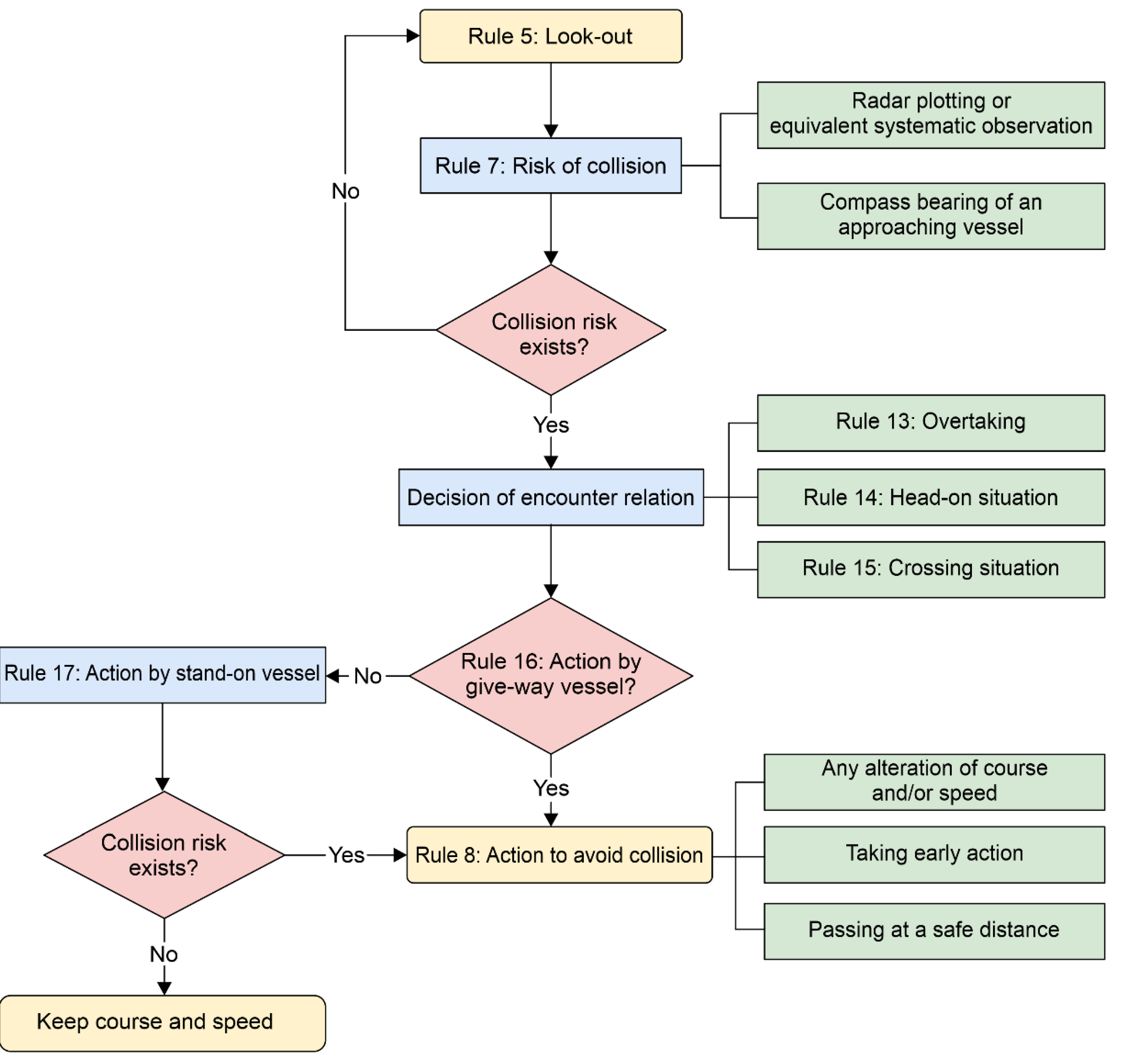
“A Guide to the Collision Avoidance Rules” [5] comprehensively examines the core COLREGs Rules through various precedents and expert discussions. In keeping with this guide, a collision avoidance process on the basis of COLREGs Rules 5, 7, 8, and 13–17 was proposed, as shown in Figure A1. First, in accordance with Rule 5, a vessel shall perform appropriate observations to ensure that the present situation and collision risk are fully assessed using all available means appropriate to the given circumstances and conditions. Second, in accordance with Rule 7, the collision risk shall be identified by considering radar plotting or equivalent systematic observations as well as the compass bearing change of an approaching vessel. Third, in accordance with Rules 13–15, the encounter type shall be determined if a collision risk exists. Finally, if a vessel is subject to Rule 16 for determining an encounter type, Rule 8 shall be followed early to avoid collision with the target ship (TS) at a safe distance through course and/or speed alterations. However, for a stand-on vessel, in accordance with Rule 17, a collision risk is determined to exist in accordance with Rule 7. If the actions of a give-way vessel eliminate the collision risk, the present course and speed shall be maintained; otherwise, a collision-avoidance action in accordance with Rule 8 shall be taken.
Table A1 lists representative local route-planning algorithms for the MASS in avoiding collisions. It was identified whether these algorithms comply with COLREGs Rules for collision avoidance as proposed [5]. All algorithms were found not to comply with the compass bearing change of an approaching vessel in accordance with Rule 7. The algorithm presented by [6] satisfied all Rules except Rule 7. However, there are two significant issues. First, if the stand-on vessel is the cause of constant collision risk, a collision-avoidance action in accordance with Rule 17 can be taken; however, the time point for this collision avoidance was not defined. Second, assuming the lengths of the MASS and TS to be the diameter, the velocity obstacle (VO) [6,7,8,9,10,11] combines the radii of the MASS and TS to formulate a circle for creating a cone-shaped danger zone. However, because this circle is smaller than the ship domain (SD), where no TS exists for preventing collision, the collision-avoidance action is taken with a collision risk always existing with no minimum safe distance being secured. In this light, in the present study, a local route-planning algorithm was developed based on the situational awareness (SA) model [12] using a fuzzy inference system based on near-collision (FIS-NC) [13], SD, and VO to ensure that a MASS complies with all essential collision-avoidance requirements based on the COLREGs Rules proposed [5] and also solves the problems of existing algorithms analyzed herein.
The remainder of this paper is organized as follows. Section 2 presents the necessary theoretical background. Section 3 uses the SA model to discuss the local route-planning algorithm based on FIS-NC, SD, and VO for collision avoidance in compliance with the COLREGs Rules. Section 4 presents MATLAB computational simulation results and the discussions. Finally, Section 5 presents the conclusions of this study.
2. Theoretical Background
2.1. Closest Point of Approach
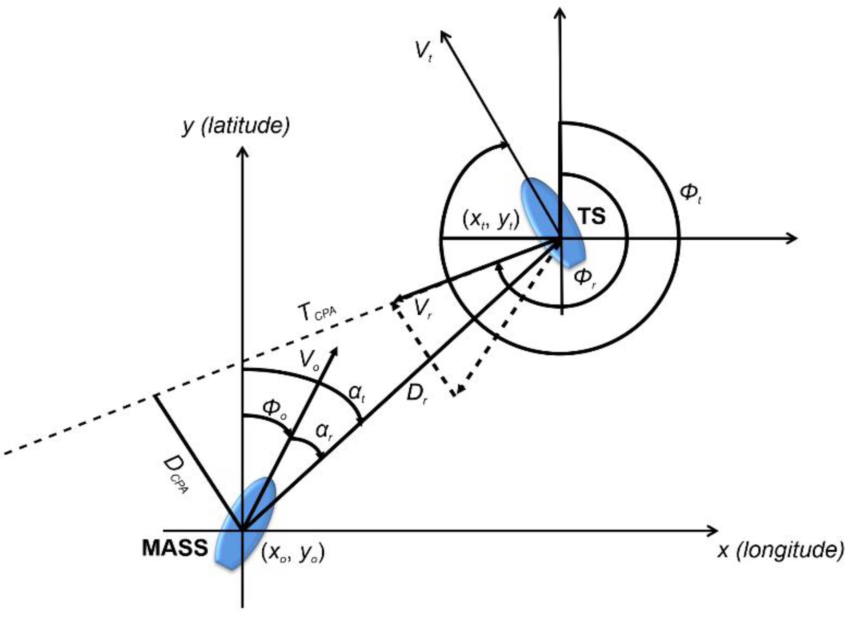
The closest point of approach (CPA) is the point where the MASS is closest to the TS at any time. Let the coordinate, course, and velocity of the MASS be , , and , respectively, and those of the TS be , , and , respectively. Then, the time until the CPA and the distance between the MASS and TS at the CPA are calculated using an automatic radar plotting aid (ARPA) and an automatic identification system (AIS) equipped in all cargo vessels, as follows:
where is the relative distance between the MASS and the TS, the relative velocity, the relative course, the azimuth of the TS, and the relative bearing. TCPA is the time to the CPA, and DCPA is the distance between the MASS and the TS at that time. TCPA can be zero, positive, or negative, and DCPA can only be zero or positive. The closer both TCPA and DCPA are to zero, the higher the collision risk. A negative TCPA means that the DCPA has already passed, that is, the vessels are moving away from each other after the closest state. Figure 1 shows an illustration of the CPA.
Following this, the variance of compass degree (VCD) [14] is calculated as
where is the current time. At this point in time, the collision risk is high when VCD approaches 0.
2.2. FIS-NC
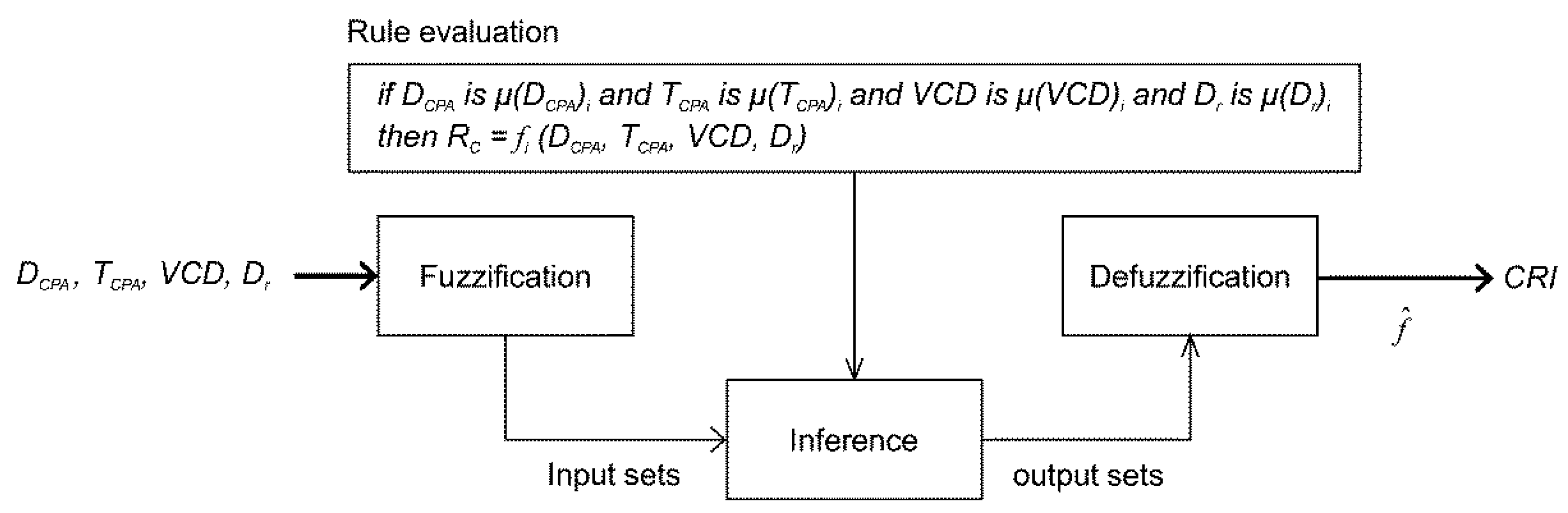
In fuzzy logic, fuzzy IF-THEN rules are used to formulate conditional statements. Figure 2 shows the inference process of the FIS-NC proposed by [13].
In the first step, inputs including DCPA, TCPA, VCD, and were collected using ARPA and AIS, and the degree to which these inputs belong to each of the appropriate fuzzy sets was determined. In the second step, the fuzzified inputs were applied to the antecedents of fuzzy rules. This result was then applied to the consequent membership function (). In the third step, aggregation was performed to unify the outputs of all rules. In the last step, the input for the defuzzification process was the aggregated output fuzzy set, and the output was calculated as the collision risk index (CRI) using the weighted average function ().
CRI ranged from 0.00 to 1.00 [13], and the time point for collision avoidance was as follows: the give-way vessel shall take a collision-avoidance action for CRI ≥ 0.01, and the stand-on vessel shall take a collision-avoidance action for CRI ≥ 0.33.
2.3. SD
The SD is a generalized safe distance area that requires the maintenance of a situation without a TS or an obstacle. This concept was introduced for preventing collisions. However, because various SDs can exist, the size and shape of the SD must be selected in keeping with what is most suitable for vessel operation [15]. After analyzing the size and shape of SDs based on AIS sea traffic data for 4 years [16], the most suitable ones for vessel operation were found to be those where the long diameter proposed by [17] was equal to a long radius of 4 and short radius of 1.6 (where is the vessel length). The elliptical SD proposed by [17] is shown in Figure 3 and given by Equations (7)–(11).
The elliptical SD of the MASS parallel to the x-axis at position is calculated as
where is the length of the MASS, and and are the long and short radii, respectively.
The location of the elliptical SD may change depending on the route of the MASS. Therefore, an elliptical SD rotation consistent with the MASS’s course is required. In Equation (7), the coordinates are rotated to to match the angle between the long radius and the -axis. Equations (8) and (9) provide the changed coordinates of the elliptical SD:
In these equations, the angle of intersection () in the heading direction of the MASS for the long radius and x-axis is determined using the angle , as shown in Equation (10). The coordinates in Equation (7) are substituted with the coordinates to obtain the rotated elliptical SD, as given by Equation (11).
However, the SD proposed by [17] had a static shape and size regardless of the change in vessel velocity. Therefore, Namgung and Kim [13] theoretically analyzed the SD proposed by [17] and [18] to obtain an SD using the length and speed of the MASS as parameters. They calculated the long radius and short radius of the SD using Equations (12) and (13), respectively, for each 0.1 velocity change.
where is 10 .
2.4. VO
The VO [19] for a vessel is the set of velocities for which it will collide with another vessel (i.e., obstacle) at some time in the future as long as both vessels keep a constant velocity. The VO collision-avoidance method aims to determine velocities that should be avoided to prevent any future collisions.
The VO for an ‘O’-shaped MASS [7] with respect to a ‘T’-shaped TS is given as
where is the position vector of the MASS, and and are the velocity of the MASS and TS, respectively. A ray starting at and going in the -direction is expressed as
where is time.
Equation (14) uses the following set operation:
By assuming that that both the MASS and the TS are circular, Equation (14) can be simplified as
where is a circle with center and radius . At this time, is aggregated with the radius of and the radius of the TS length as
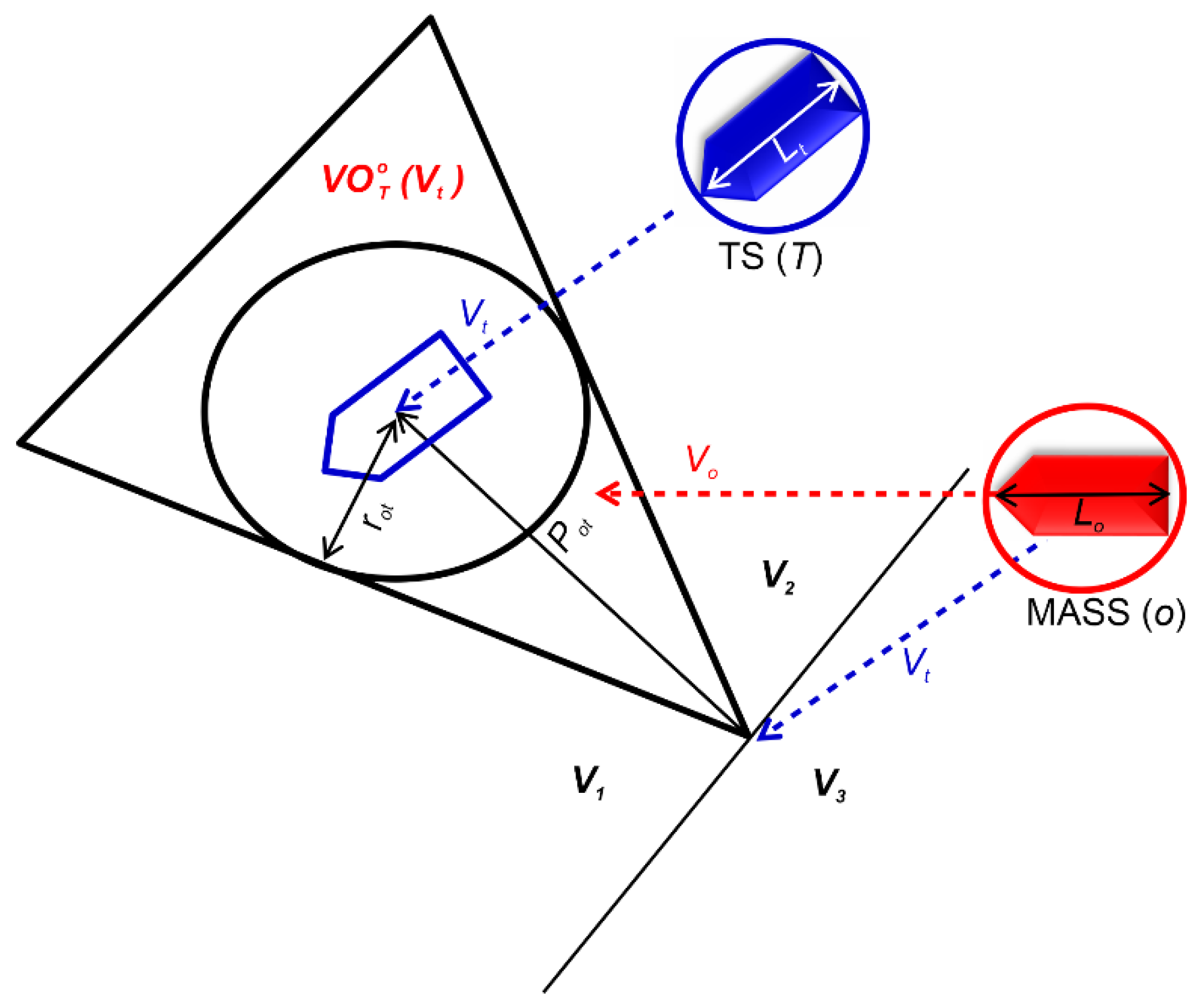
The VO for a vessel with a TS present is represented by a cone-shaped danger zone in the velocity space (i.e., VO cone), as shown in Figure 4.
As long as the vessel maintains a velocity outside the VO cone and assuming that the velocity vectors are constant over time, it will not collide with the TS. At this time, a TS close to the MASS will produce a wide cone whereas one that is further away will produce a narrower cone.
The velocity space can be divided into four different regions , , , and , where
If a velocity within is chosen, the MASS will collide with the TS at some time in the future. If velocity of , , or is chosen, the MASS will pass the TS on the port or starboard side, or it will move away from the TS.
3. Local Route Planning Using Collision Avoidance in Compliance with COLREGs Rules
3.1. Determination of Encounter Type
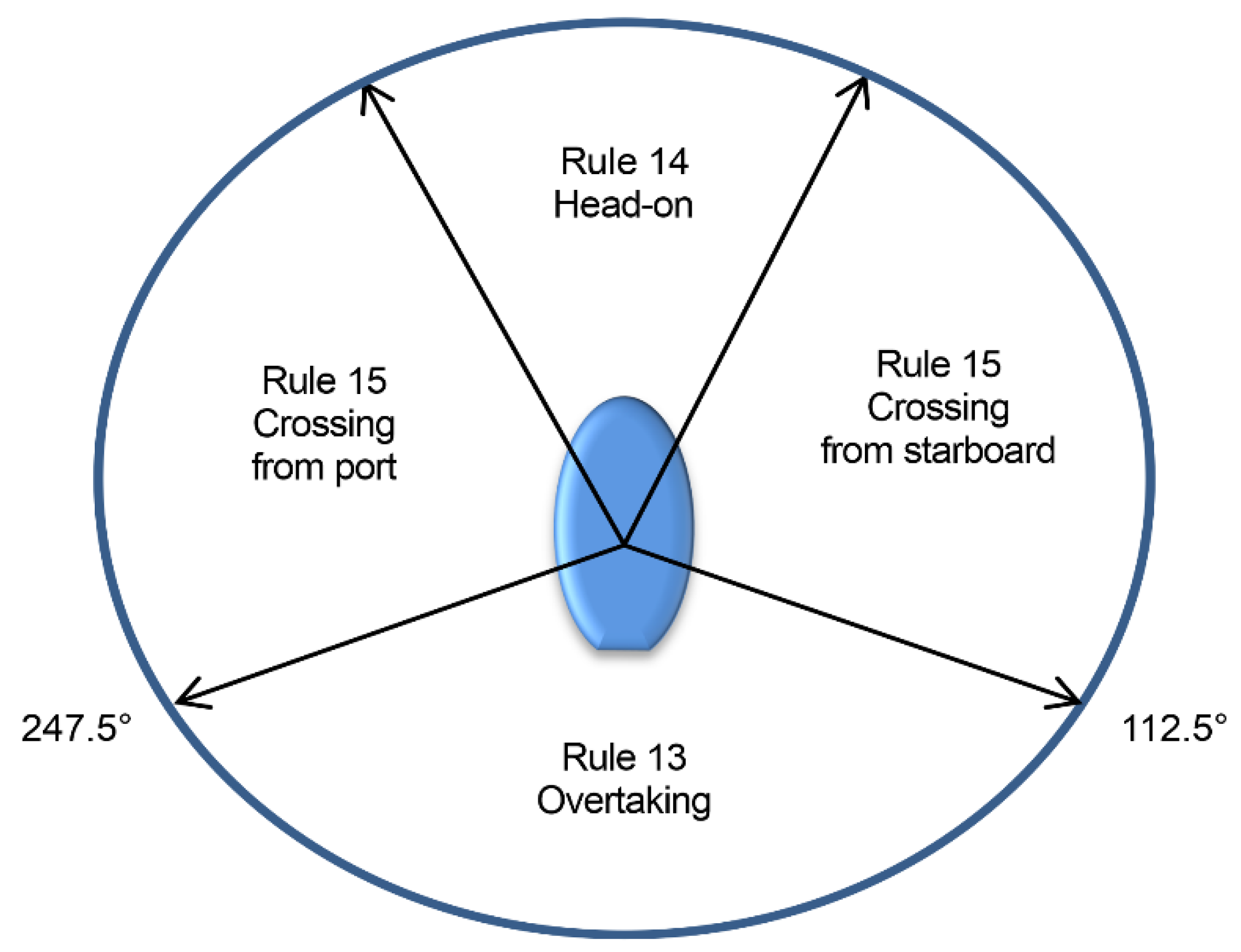
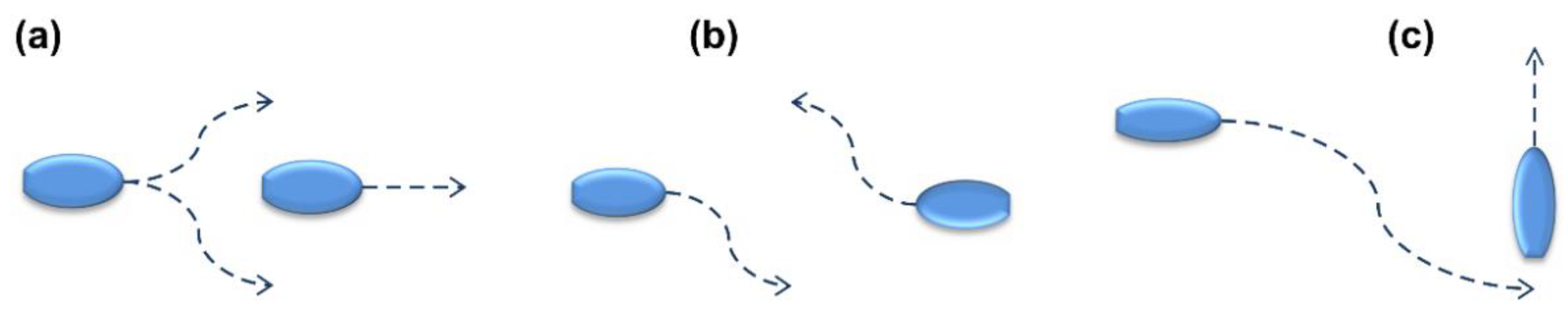
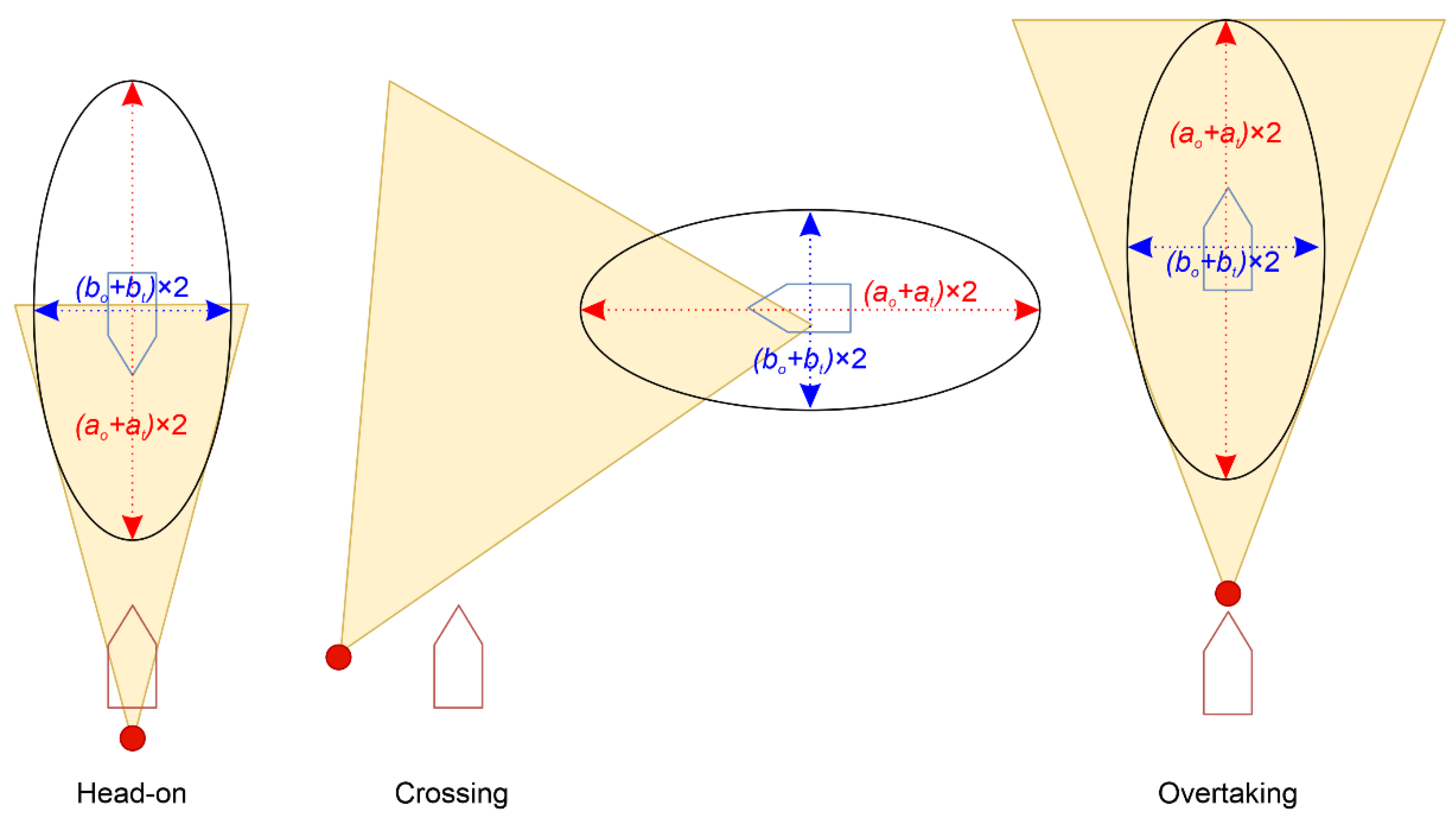
The collision-avoidance actions for the give-way and stand-on vessels are determined for overtaking, head-on, and crossing situations according to COLREGs Rules 13–17, as shown in Figure 5 and Figure 6.
- Overtaking: For an overtaking situation, the vessel being overtaken should keep a steady speed and course. COLREGs Rule 13 allows the overtaking vessel to pass the other vessel on either side, as shown in Figure 6a.
- Head-on situation: For a head-on situation, both vessels should take collision-avoidance actions by changing their course to the starboard, as shown in Figure 6b.
- Crossing situation: When crossing from either port or starboard, the vessel which has the other vessel on its starboard side is considered the give-way vessel, and it should alter its course so that it passes behind the other vessel. The other vessel should keep a steady speed and course, as shown in Figure 6c.
However, because COLREGs Rules 13–15 only determine encounter types using on the sector, as shown in Figure 6, unnecessary actions may be taken by a TS that does not approach the MASS.
Therefore, [20,21,22] determined encounter types using , , and . Table 1 shows a comparative analysis of these methods.
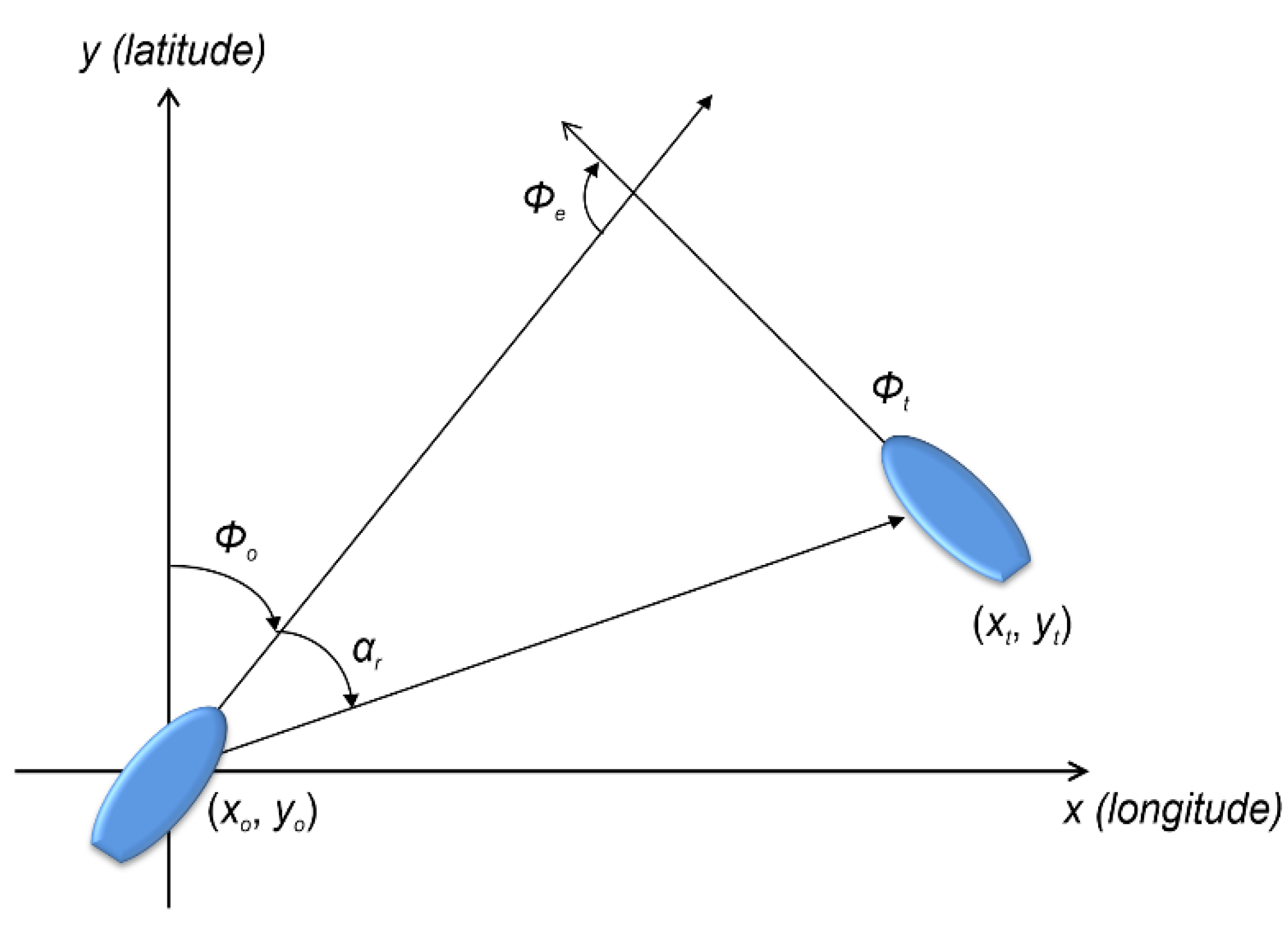
Here, is the encounter angle, as shown in Figure 7 and given by Equation (22). If is negative, 360° is added in Equation (22).
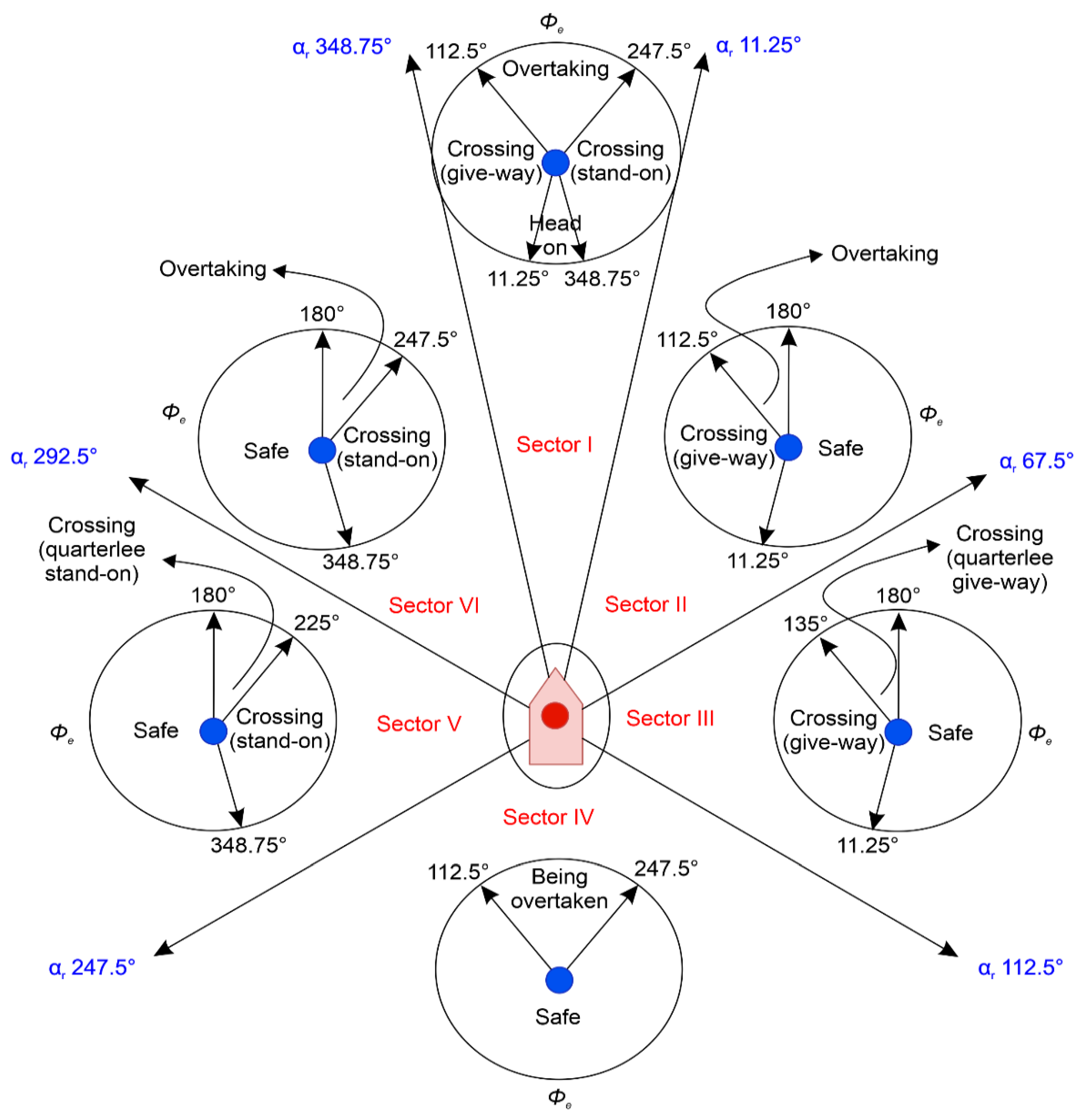
Existing methods have their own characteristics, as listed in Table 2. In the present study, the encounter type was determined by combining these characteristics based on the method proposed by [21], as shown in Table 3. This is because the determination of the encounter type in overtaking and crossing situations can be distinguished by the circumstances, as shown in Table 2 (b) and (c).
Figure 8 shows the determination of the encounter type based on Table 3. A sector is divided into six parts, with the range of sector angles being . The circle in each sector indicates the encounter type determined by .
Algorithm 1 shows the determination of the encounter type between the MASS and the TS based on Figure 8. This process can largely be divided into two parts. First, if a collision risk exists, the MASS shall identify where the TS is located in the sector using . Second, the encounter type between the MASS and the TS is determined by in the identified sector.
| Algorithm 1. Determination of Encounter Type Between MASS and TS. |
| Input: , Output: Encounter type 1 while collision risk exists 2 if TS is in ‘Sector Ⅰ’ determined with then 3 if () and () or () and () then 4 decide ← head-on situation of MASS 5 else if () and () then 6 decide ← crossing situation (give-way) of MASS 7 else if () and () then 8 decide ← overtaking situation (overtaking) of MASS 9 else if () and () then 10 decide ← crossing situation (stand-on) of MASS 11 else if TS is in ‘Sector Ⅱ’ determined with then 12 if () and () then 13 decide ← crossing situation (give-way) of MASS 14 else if () and () then 15 decide ← overtaking situation (overtaking) of MASS 16 else if () and () or () and () then 17 decide ← safe (keep a steady speed and course) of MASS 18 else if TS is in ‘Sector Ⅲ’ determined with then 19 if () and () then 20 decide ← crossing situation (give-way) of MASS 21 else if () and () then 22 decide ← crossing situation (quarter lee give-way) of MASS 23 else if () and () or () and () then 24 decide ← safe (keep a steady speed and course) of MASS 25 else if TS is in ‘Sector Ⅳ’ determined with then 26 else if () and () then 27 decide ← overtaking situation (being overtaken) of MASS 28 else if () and () or () and () then 29 decide ← safe (keep a steady speed and course) of MASS 30 else if TS is in ‘Sector Ⅴ’ determined with then 31 if () and () then 32 decide ← crossing situation (quarter lee stand-on) of MASS 33 else if () and () then 34 decide ← crossing situation (stand-on) of MASS 35 else if () and () or () and () then 36 decide ← safe (keep a steady speed and course) of MASS 37 else if TS is in ‘Sector Ⅵ’ determined with then 38 else if () and () then 39 decide ← crossing situation (stand-on) of MASS 40 else if () and () then 41 decide ← overtaking situation (overtaking) of MASS 42 else if () and () or () and () then 43 decide ← safe (keep a steady speed and course) of MASS 44 end 45 end |
3.2. Collision-Avoidance Action Based on VO Using SD
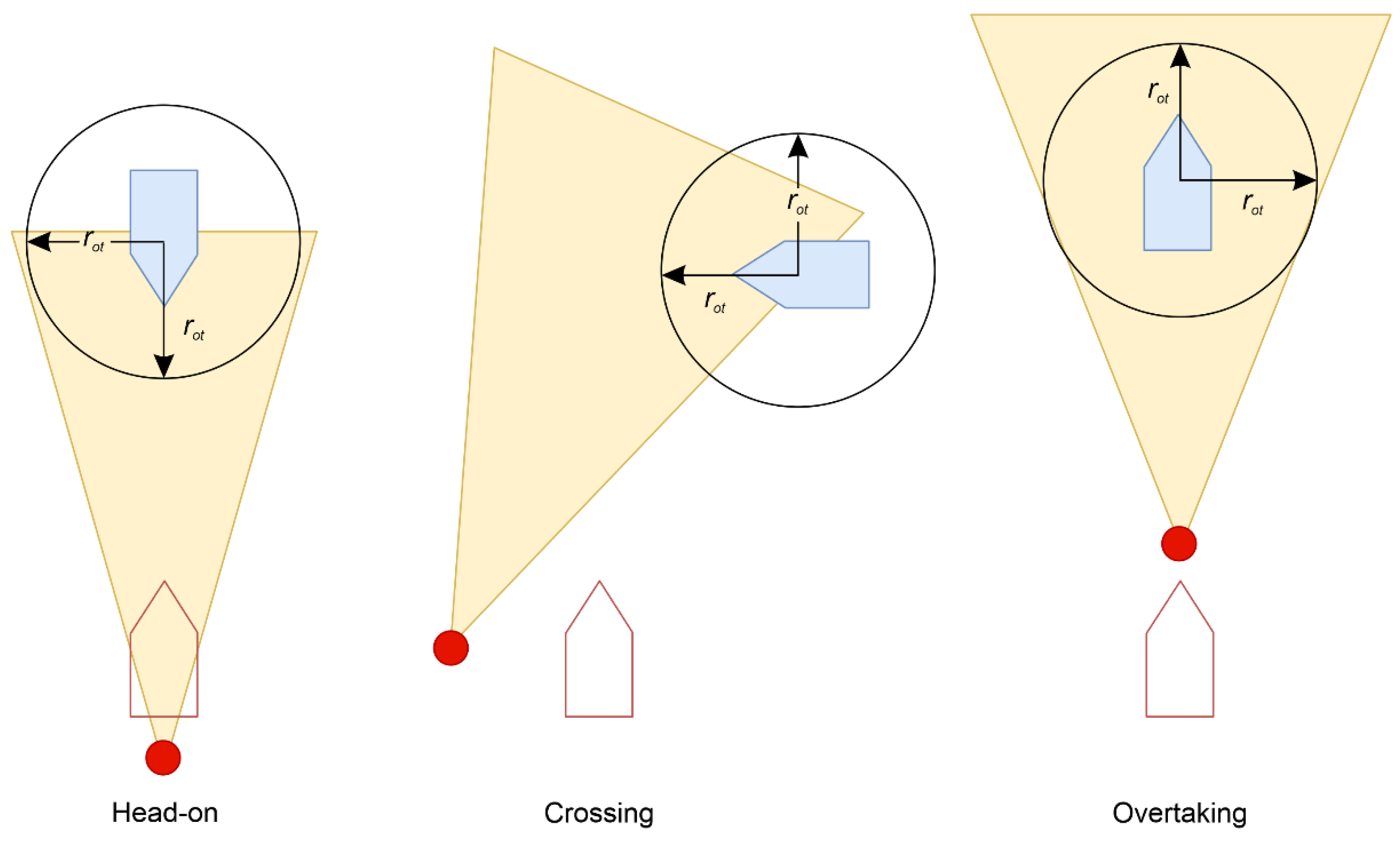
According to the encounter type, the collision-avoidance action using based on can be expressed as shown in Figure 9.
In this figure, the beige-shaded area is the cone-shaped danger zone of .
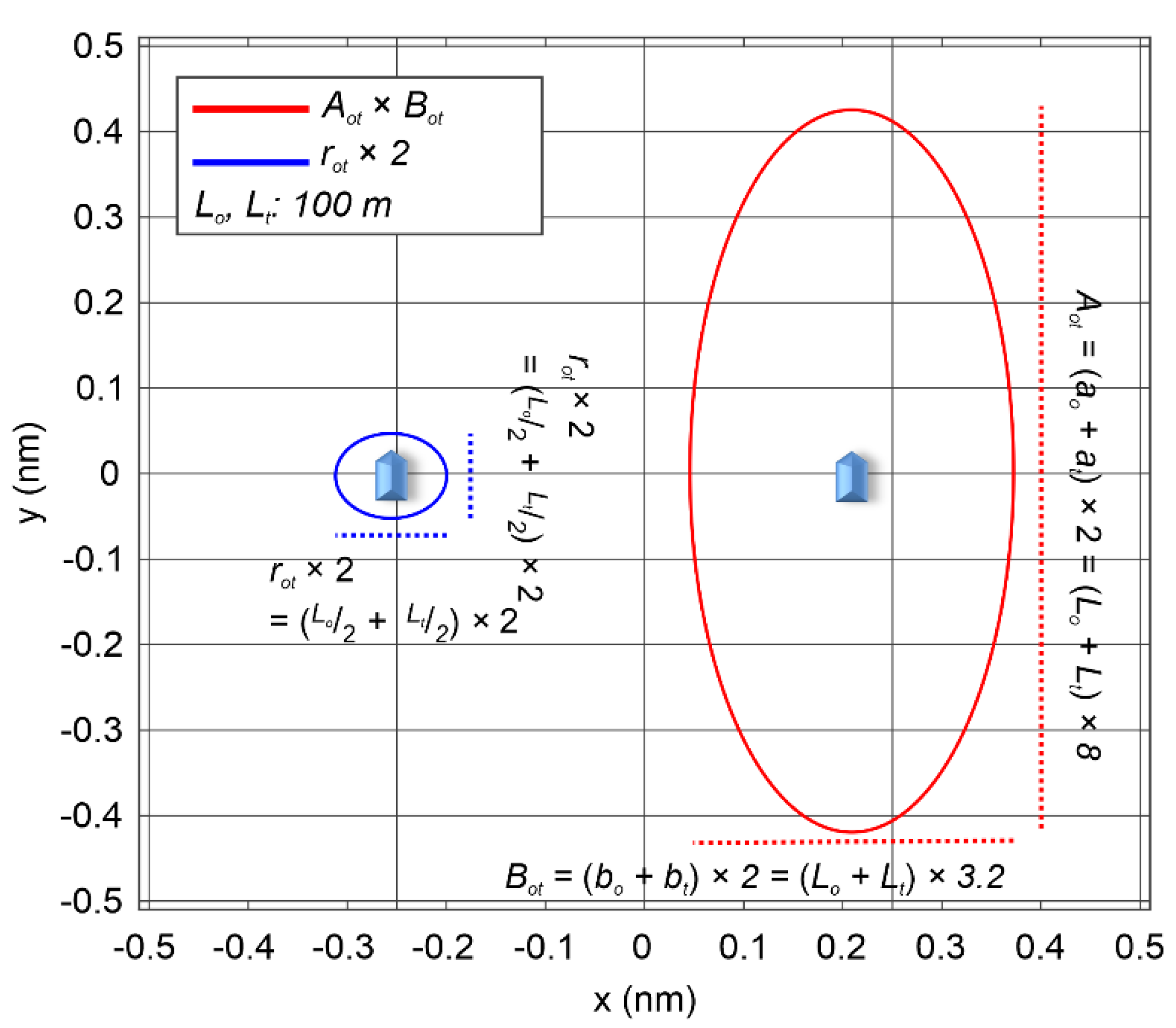
Figure 10 shows a comparison of the size of the SD proposed by [13] and the size of the circle using , with both the MASS and the TS sail at 10 .
At this time, to represent a cone-shaped danger zone, the sizes of the SDs of the MASS and TS were added as shown in Equation (23):
where and are the long radius and short radius of the TS, respectively, and and are the long radius and short radius of the added SD of the MASS and TS.
The size comparison indicated that the -based circle was times the long diameter and times the short diameter of the added SD of the MASS and TS. In other words, VO using the -based circle always causes a collision-avoidance action with a collision risk with no minimum safe distance being secured. Thus, a minimum safe distance was secured by creating based on the using Equation (23) instead of , as shown in Equation (24) and Figure 11.
3.3. Development of Local Route-Planning Algorithm
SA [12] can be defined as the detection of continuous changes to the surrounding environment, the understanding of what is happening, and the prediction of what will happen in the near future based on the current state—it focuses on the selection, processing, transmission, and utilization of information from a changing environment. Reference [12] proposed the following three-step approach for the SA:
- Perception (Level 1 SA): The first step in achieving SA is to perceive the status, attributes, and dynamics of relevant elements in the environment. Specifically, Level 1 SA involves monitoring, cue detection, and simple recognition processes which lead to an awareness of multiple situational elements (e.g., objects, events, people, systems, environmental factors) and their current states (e.g., locations, conditions, modes, actions).
- Comprehension (Level 2 SA): The next step in achieving SA involves synthesizing disjointed Level 1 SA elements through pattern recognition, interpretation, and evaluation processes. Level 2 SA involves integrating this information to understand how it will impact upon the individual’s goals and objectives.
- Projection (Level 3 SA): The third step in achieving SA is projecting the future actions of the elements in the environment. Level 3 SA involves extrapolating information about the status and dynamics of the elements and comprehension of the situation (Levels 1 and 2 SA) forward in time to determine how it will affect future states of the operational environment.
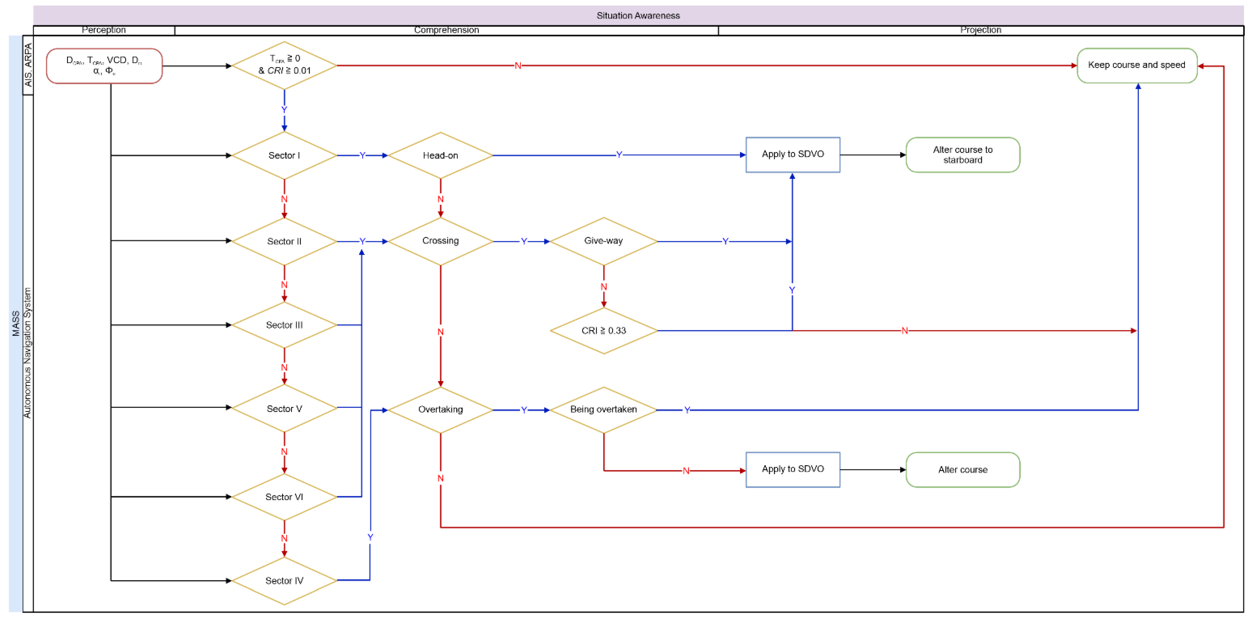
Figure 12 shows the local route-planning procedure of the MASS based on SA.
In the perception step, the DCPA, TCPA, VCD, and between the MASS and the TS were collected using ARPA and AIS. In the comprehension step, if TCPA is 0 or more, and the CRI inferred using FIS-NC is 0.01 or more, the MASS determines the encounter type based on Algorithm 1. In the projection step, a collision-avoidance action is taken with in head-on, crossing (give-way, including quarter lee give-way), and overtaking (overtaking) situations. In particular, if the inferred CRI in the crossing situation (stand-on, including quarter lee stand-on) is less than 0.33, the MASS keeps a steady speed and course; however, if it is 0.33 or more, the MASS takes a collision-avoidance action with . In all other cases, the MASS keeps a steady speed and course.
As a result, the local route-planning algorithm for the MASS was developed as follows (Algorithm 2):
| Algorithm 2. Local Route Planning. |
| Input: , , , , , , , Output: 1 Initialize ← keep a steady speed and course 2 while and do 3 if ← head-on situation of MASS ║ crossing situation (give-way) of MASS ║ crossing situation (quarter lee give-way) of MASS then 4 5 choose ← alter course to starboard 6 else if ← crossing situation (stand-on) of MASS ║ crossing situation (quarter lee stand-on) of MASS then 7 if then 8 9 choose ← alter course to starboard 10 else 11 ← keep a steady speed and course 12 end 13 else, if ← overtaking situation (overtaking) of MASS then 14 15 choose ← alter course to port ║ ← alter course to starboard 16 else if ← overtaking situation (being overtaken) of MASS ║ safe situation of MASS then 17 ← keep a steady speed and course 18 end 19 end 20 end |
4. Results and Discussion
4.1. Simulation Results
The performance of the local route-planning algorithm developed in Section 3.3 is validated for the collision avoidance of the MASS. This algorithm is referred to as SDVO + FIS-NC because it takes a collision-avoidance action based on the FIS-NC and . First, SDVO + FIS-NC and existing local route-planning algorithms were applied and compared in each encounter type for a single vessel. Two existing algorithms were selected for this purpose: the A* exploration-based local route-planning algorithm using the FIS [23] and the VO-based local route-planning algorithm using fuzzy comprehension evaluation (VO + FCE) [6] for taking collision-avoidance actions at a suitable time point based on fuzzy logic. Second, whether the MASS with SDVO + FIS-NC properly took collision-avoidance actions in more complex encounter types with multiple vessels was analyzed. At this point, the time of return to the way point after the collision-avoidance action was regarded as being when the negative TCPA occurred.
4.1.1. Avoiding Single Vessel
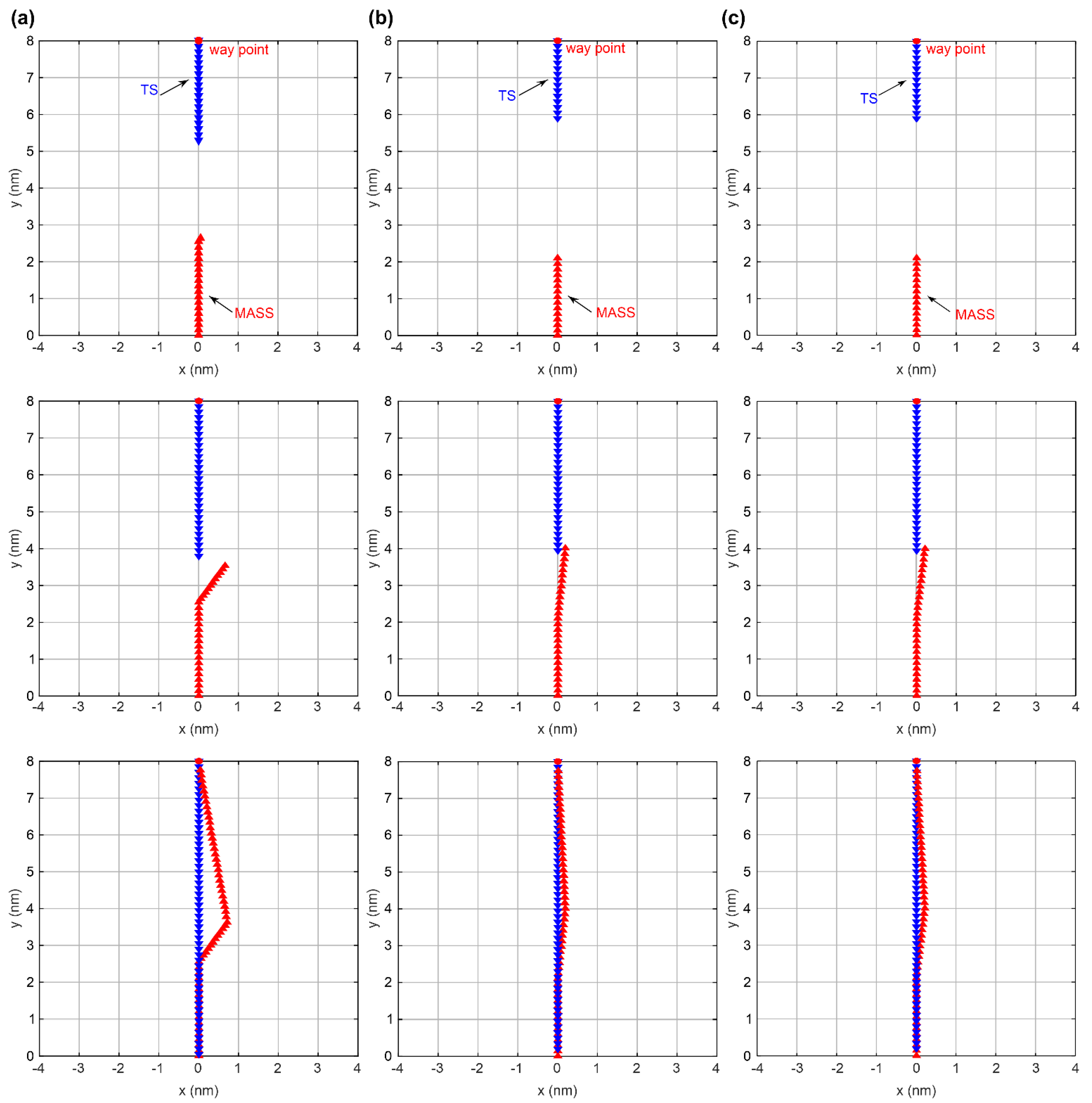
The head-on, crossing (give-way and stand-on), and overtaking encounter types with a single vessel were tested. Table 4 shows the initial conditions of the MASS and TS.
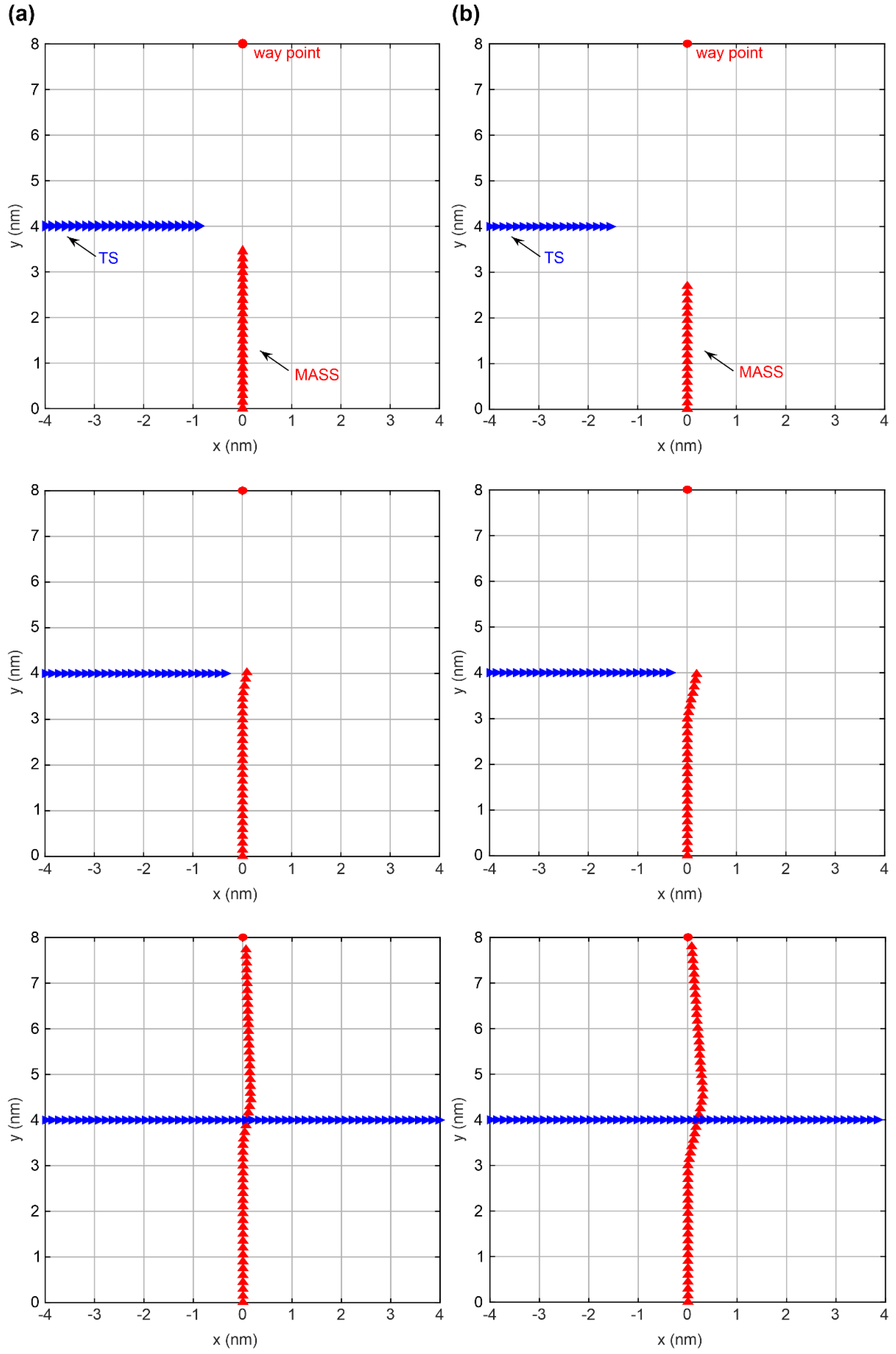
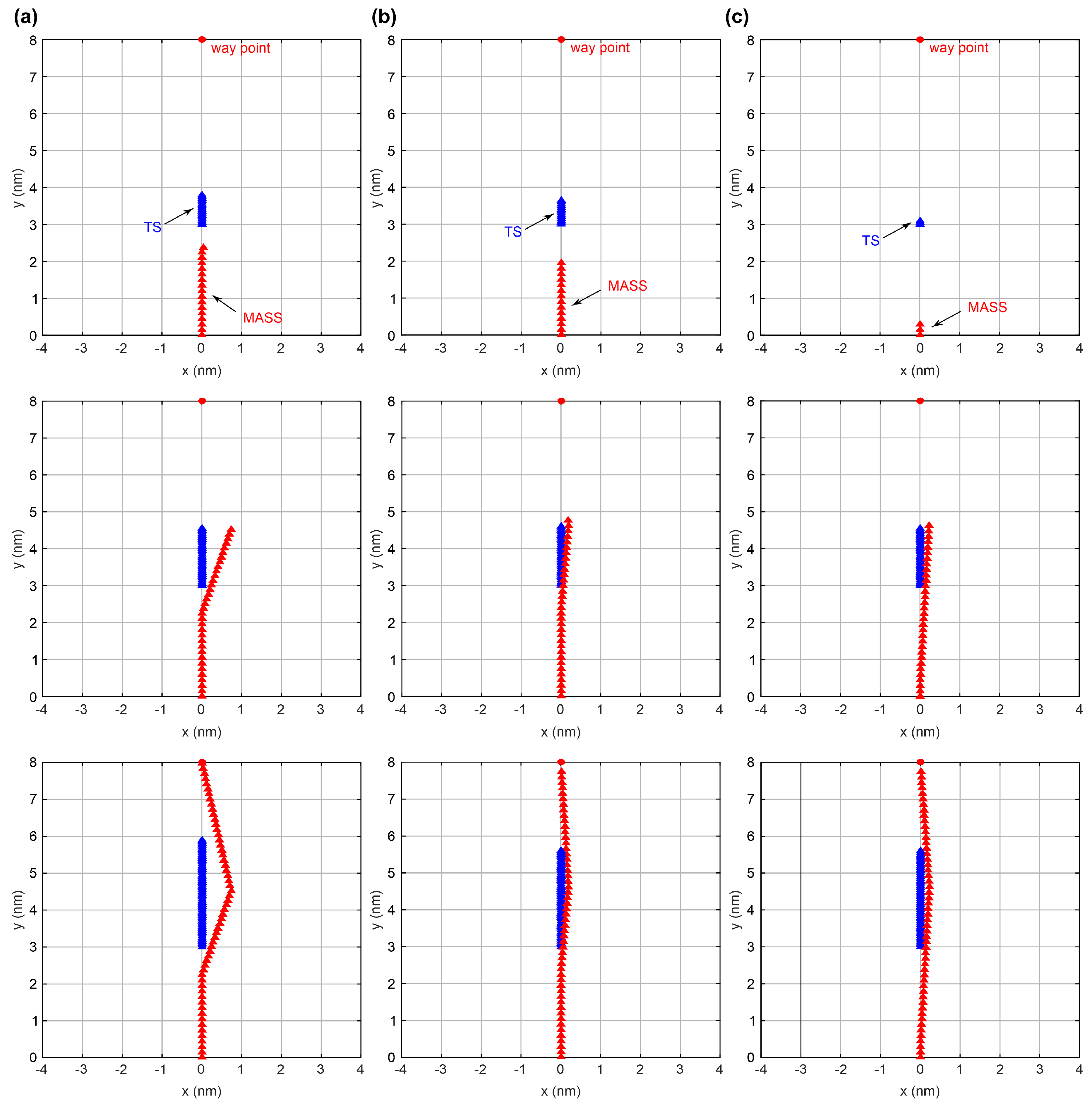
Figure 13, Figure 14, Figure 15 and Figure 16 show that the MASS takes collision-avoidance actions upon approaching the TS by applying FIS, VO + FCE, and SDVO + FIS-NC in the different encounter types according to Table 4. The MASS applied each local route-planning algorithm to the generated local route in real time by determining the time point for collision avoidance according to the CRI, encounter type, and collision-avoidance action. The time point for collision avoidance with VO + FCE was not defined for crossing (stand-on), and therefore, it is excluded in Figure 15.
Table 5 shows the margin , response distance, and course angle for collision avoidance at the coordinates when the criteria CRI of each algorithm were equaled or exceeded for give-way and stand-on vessels according to the encounter type. At this time, the response distance and course angle for the collision avoidance begin from 0 at coordinates .
4.1.2. Avoiding Multiple Vessels
The head-on, crossing (give-way and stand-on), and overtaking encounter types with multiple vessels were tested for TSs approaching the MASS, as shown in Table 8. All TSs were set up to take collision-avoidance actions using the VO [7] with DCPA and TCPA.
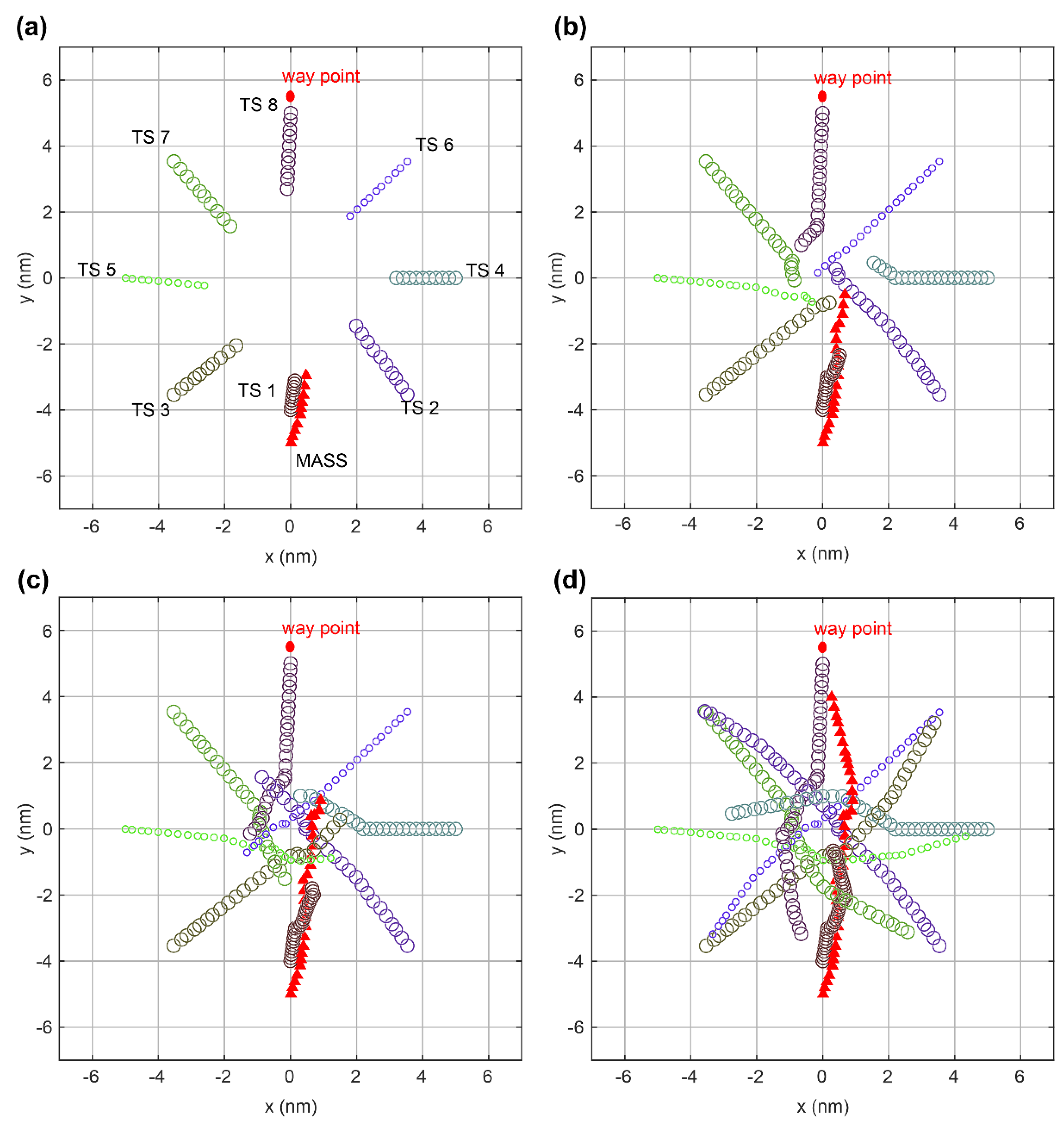
The MASS using SDVO + FIS-NC took collision-avoidance actions in an encounter type with multiple vessels, as shown in Figure 17.
Initially, the MASS analyzed whether TCPA is 0 or more, and the CRI inferred using FIS-NC was 0.01 or more. TS1 was confirmed to be applied. This encounter type was considered an overtaking situation. The MASS was the overtaking vessel, and TS1 was the vessel being overtaken. Then, the MASS overtook TS1 by turning to starboard. After overtaking, because the TCPA and CRI of TS3 and TS5 were 0 or more and 0.01 or more, respectively, the MASS determined the encounter type and collision-avoidance action. This encounter type was considered a crossing situation. The MASS was the stand-on vessel, and TS3 and TS5 were give-way vessels. Nonetheless, TS3 and TS5 did not take early collision-avoidance actions. Thus, the MASS kept a steady speed and course when the CRI was less than 0.33 and then turned to starboard when it was 0.33 or more. After the collision avoidance of TS3 and TS5, the MASS identified that the TCPA and CRI of TS4 were 0 or more and 0.01 or more, respectively, and this encounter type was considered a crossing situation. The MASS was the give-way vessel and TS4 was the stand-on vessel. Therefore, the MASS took an early collision-avoidance action by turning to starboard immediately to return to its original route.
4.2. Discussion
The simulation results showed that SDVO + FIS-NC could avoid the TS according to COLREGs Rules 5, 7, 8, and 13–17, via Algorithms 1 and 2. In this section, the quality of the local route created by SDVO + FIS-NC is discussed in terms of safety and effectiveness during navigation.
First, a comparative analysis was conducted on the safety and effectiveness during navigation of a MASS and a single TS based on the results of each local route-planning algorithm. Safety was verified using the overlapped SD and inferred CRI. Effectiveness was verified using the course angle and deviation from the original route.
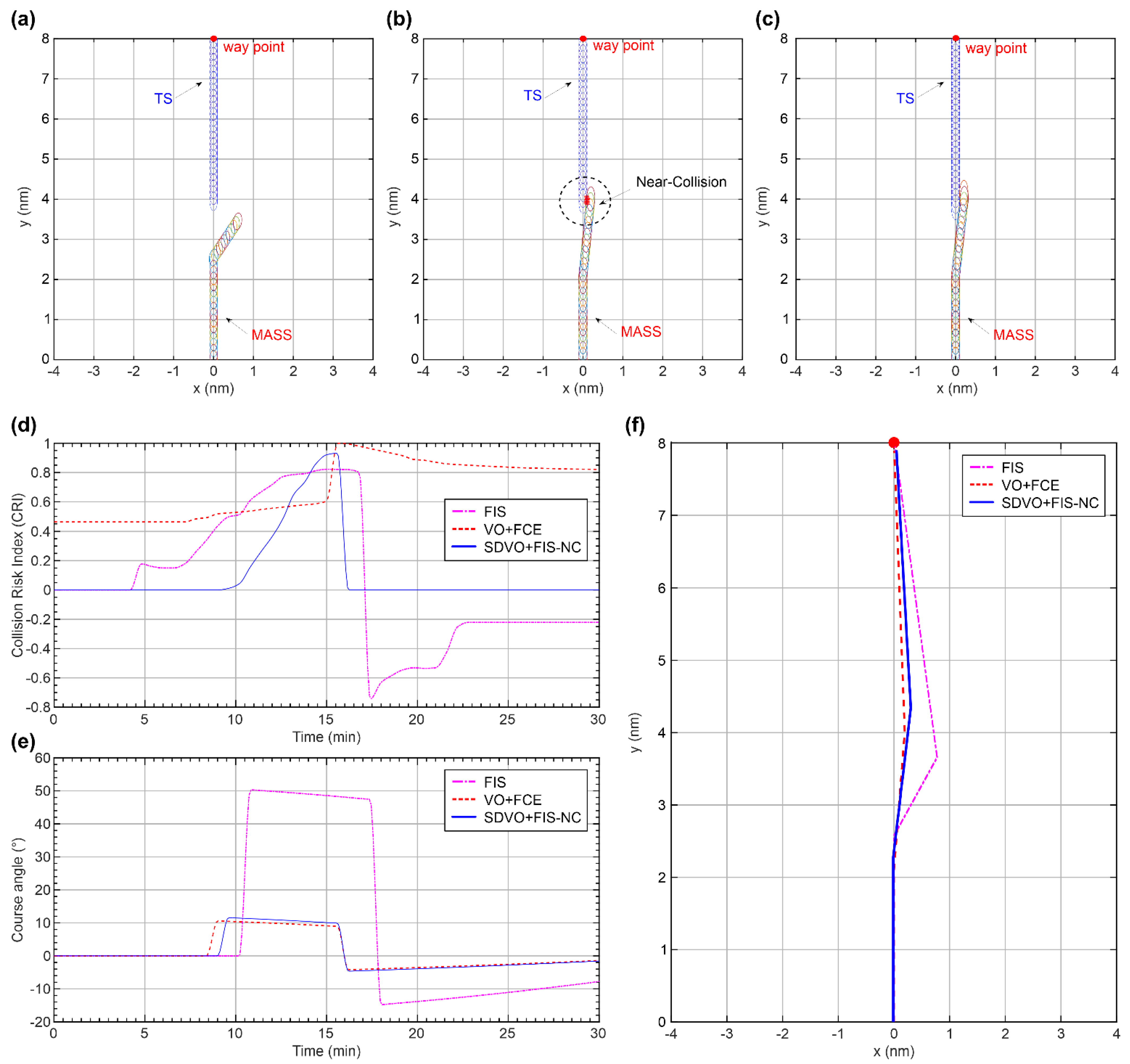
Figure 18, Figure 19, Figure 20 and Figure 21 show comparative results from the beginning of collision avoidance with the TS to the return to the original route.
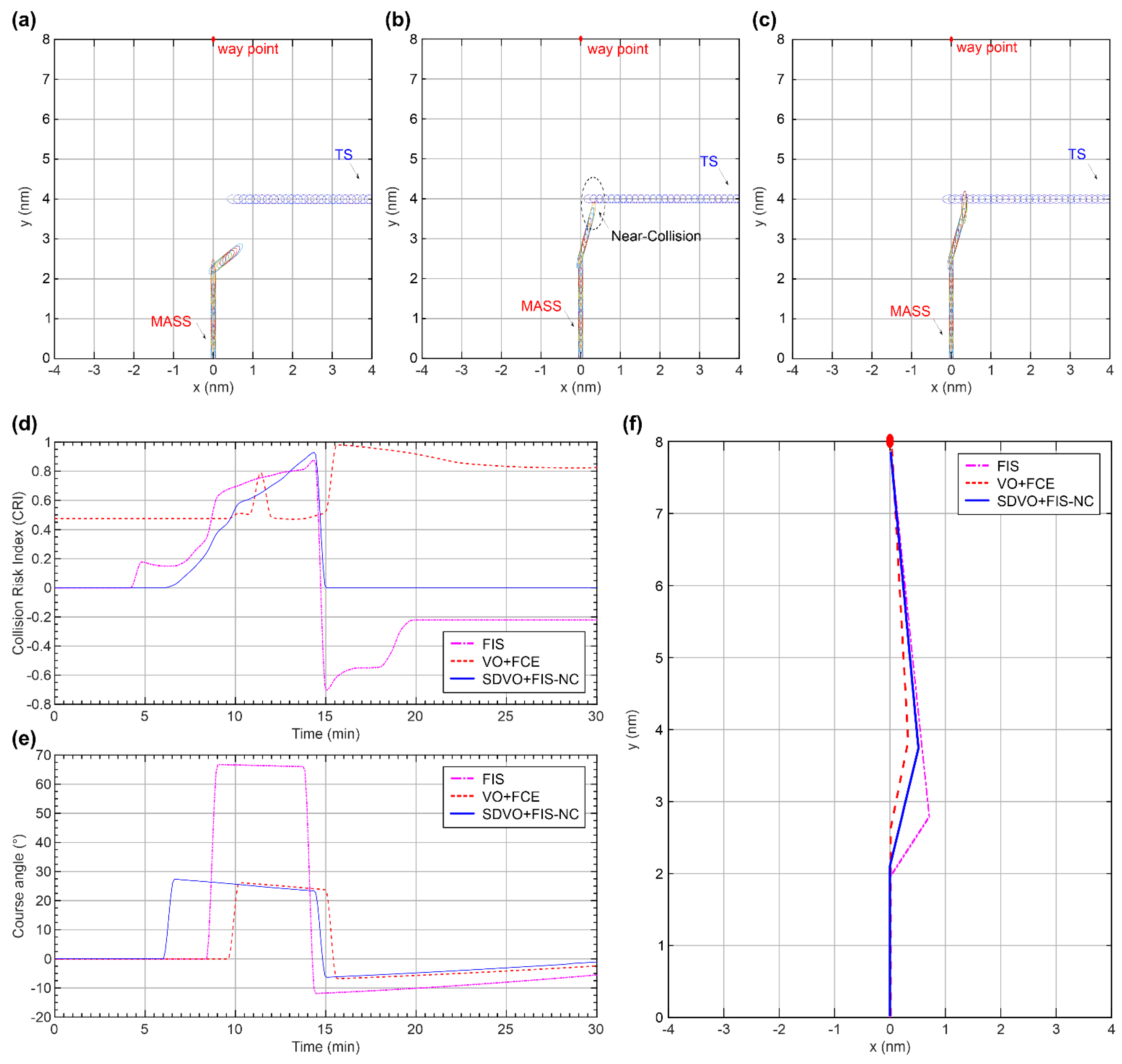
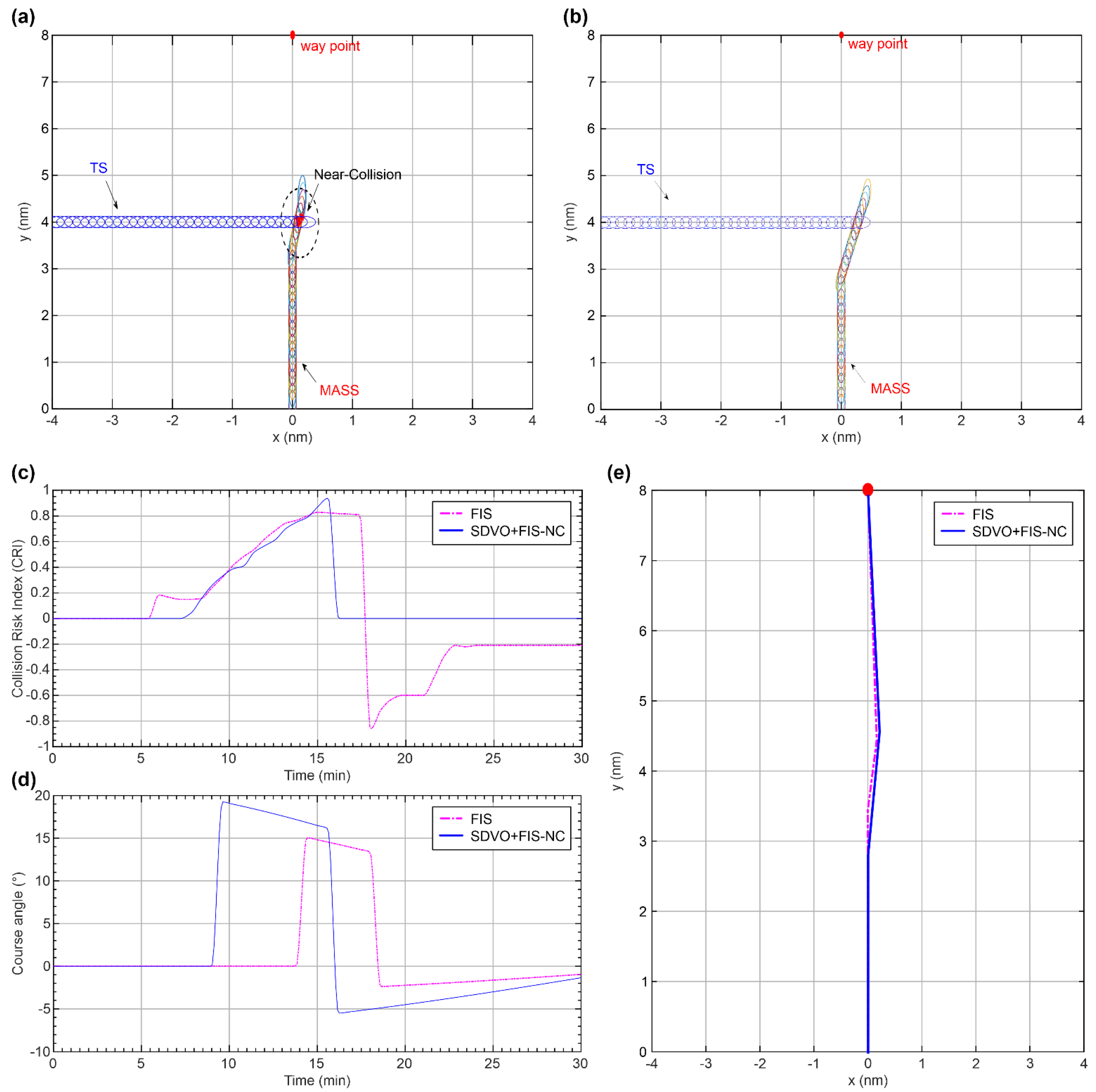
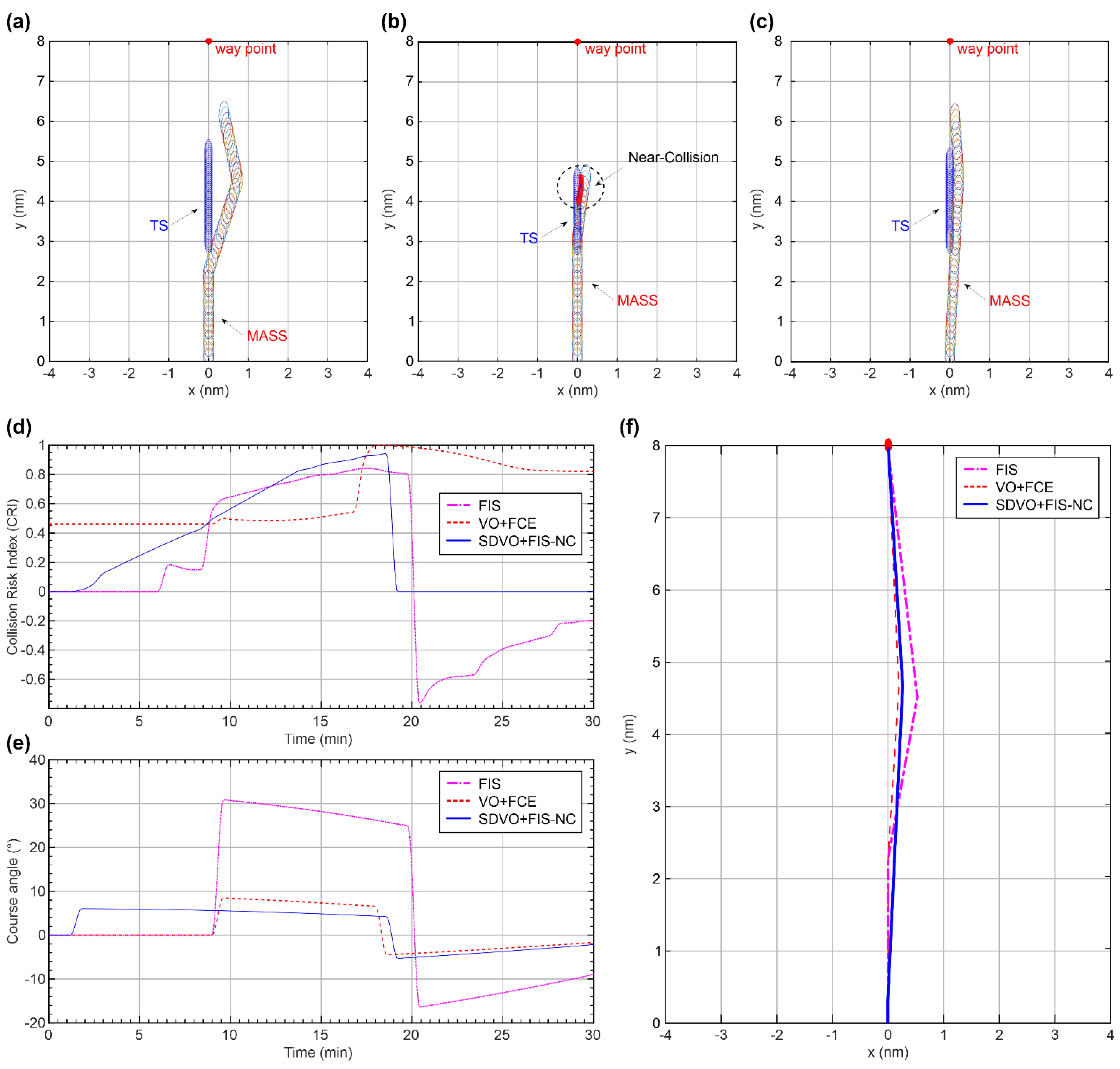
Figure 18, Figure 19, and Figure 21 show the MASS as the give-way vessel, and Figure 20 shows the MASS as the stand-on vessel. Figure 18a–c, Figure 19a–c, Figure 20a–b, and a–c show whether the SD [13] applied to both vessels is overlapped. In this paper, an overlapped domain indicates a near-collision accident involving passing each other in a closed state with no minimum safe distance [15]. As a result of applying the SD to both vessels, FIS resulted in a near-collision accident in the crossing situation (stand-on vessel), and VO + FCE resulted in a near-collision accident in all encounter types. However, SDVO + FIS-NC did not result in a near-collision accident in any encounter type. Figure 18d, Figure 19d, Figure 20c, and Figure 21d show the changes in the inferred CRI. In spite of the gentle decrease in numerical changes in the input variables, the CRI inferred from the FIS increased and decreased, and the CRI inferred from the VO + FCE increased steeply. In contrast, the CRI inferred from the SDVO + FIS-NC increased gently according to a numerical change in the input variables, because the VCD did not change appreciably with respect to the collision-avoidance action. In particular, the VCD of the SDVO-FIS-NC was appropriately utilized in terms of the response distance for collision avoidance, as shown in Table 5, because the response distance of SDVO + FIS-NC was faster than those of FIS and VO + FCE. Figure 18e, Figure 19e, Figure 20d, and Figure 21e show the course angles for collision avoidance, and Figure 18f, Figure 19f, Figure 20e, and Figure 21f show the deviation from the original route. At this time, the value of deviation from the original route was identified as shown in Table 7. For the give-way vessel, the local route-planning algorithms with the most deviation from the course angle and route were FIS, SDVO + FIS-NC, and VO + FCE in order. For the stand-on vessel, SDVO + FIS-NC deviated slightly more from the course angle and route than FIS to prevent a near-collision accident.
Therefore, the results of local route-planning algorithms for taking safe and effective collision-avoidance actions between a MASS and a single TS during navigation can be summarized as follows. SDVO + FIS-NC took collision-avoidance action by minimizing the deviation from the course angle and original route, with no near-collision accident occurring for both the give-way and the stand-on vessels. This is because this algorithm created based on . This result confirmed that SDVO + FIS-NC achieved safe and effective navigation.
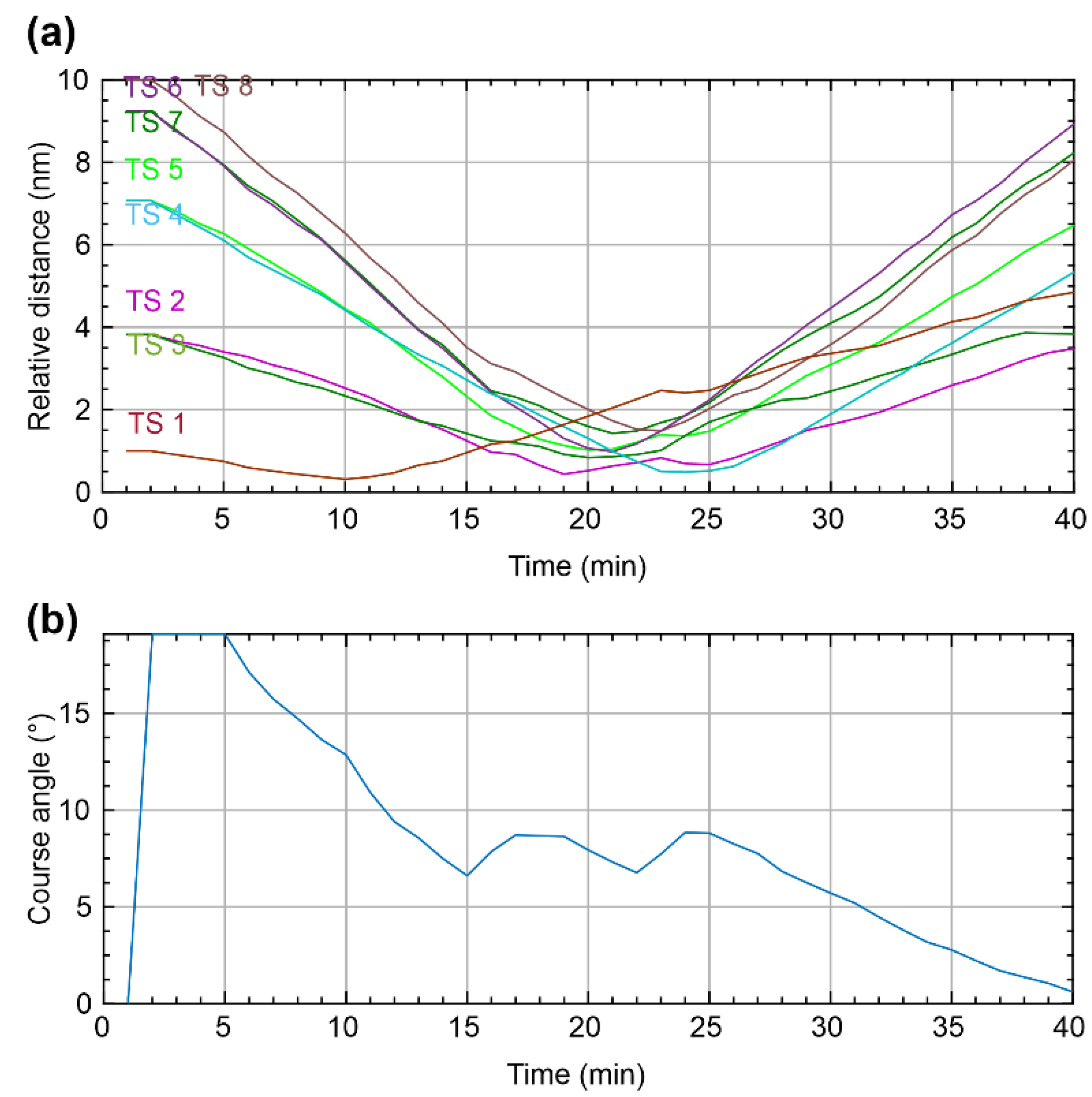
Next, the safety and effectiveness of SDVO + FIS-NC during navigation between the MASS and multiple TSs were analyzed. SDVO + FIS-NC took a collision-avoidance action to the extent that no near-collision accident occurred and the vessel also did not deviate significantly from the original route, as shown in Figure 22. This result confirmed that SDVO + FIS-NC can take safe and effective collision-avoidance actions during navigation between the MASS and multiple TSs.
Accordingly, SDVO + FIS-NC can not only reduce the navigation distance and time, but also prevent near-collision accidents in heavy traffic or confined water, because the deviation from the original route is minimized.
5. Conclusions
To operate a MASS at sea, a new route must be planned in real time to avoid collisions with a TS by taking collision-avoidance actions in compliance with COLREGs Rules. Therefore, a local route-planning algorithm based on FIS-NC, SD, and VO was developed based on the SA model. This algorithm consists of perception, comprehension, and projection steps. In the perception step, data pertaining to the navigation between the MASS and the TS were collected using AIS and ARPA. In the comprehension step, if TCPA was 0 or more and the CRI inferred using FIS-NC was 0.01 or more via the information collected in the perception step, the MASS determined the give-way and stand-on vessels according to the encounter type. In the projection step, local route planning was carried out using when a collision-avoidance action was required. For validating the performance of the developed SDVO + FIS-NC local route-planning algorithm, the following process was carried out. First, SDVO + FIS-NC and existing local route-planning algorithms, namely, the A* exploration-based local route-planning algorithm using FIS and the VO + FCE, were applied and compared for each encounter type with a single vessel. As a result, only SDVO + FIS-NC took collision-avoidance action by minimizing deviations from the course angle and original route, and no near-collision accident occurred. Next, the collision-avoidance action of SDVO + FIS-NC was analyzed between the MASS and approaching multiple TSs. As a result, SDVO + FIS-NC took systematic collision-avoidance actions using TCPA, CRI, and to the extent that no near-collision accident occurred, and the vessel did not deviate significantly from the original route. Thus, SDVO + FIS-NC is expected to not only reduce the distance and time of navigation owing to minimal differences in the original route but also prevent near-collision accidents in heavy traffic or confined water. This study is the first step toward the development of a local route-planning algorithm that can take collision-avoidance actions compliant with COLREGs Rules for a MASS. Future studies will focus on using SDVO + FIS-NC to take collision-avoidance actions in consideration of vessel dynamics, speed changes of the TS, and environmental conditions (e.g., wind, waves, and currents).
Funding
This research was funded by the Basic Science Research Program through the National Research Foundation of Korea (NRF) by the Ministry of Education, grant number 2020R1I1A1A01060533.
Institutional Review Board Statement
Not applicable.
Conflicts of Interest
The author declares no conflict of interest.
Appendix A
Figure A1.
Collision avoidance process based on COLREGs rules.


Table A1.
Comparison and analysis of representative local route-planning algorithms.
| Algorithm | Reference | Rule 5 | Rule 7 | Rule 13 | Rule 14 | Rule 15 | Rule 16 | Rule 17 | Rule 8 | ||||
|---|---|---|---|---|---|---|---|---|---|---|---|---|---|
| Available Means | Alteration of Course | Alteration of Speed | Safe Distance | Avoiding Multi-Vessels | |||||||||
| Radar Plotting | Changing of Compass Bearing | ||||||||||||
| Genetic algorithm (GA) | [24] | √ | √ | - | √ | √ | √ | √ | - | √ | - | √ | - |
| Evolutionary algorithm | [25] | √ | √ | - | √ | √ | √ | √ | √ | √ | - | √ | √ |
| Fuzzy logic | [26] | √ | √ | - | √ | √ | √ | √ | - | √ | √ | √ | - |
| Fuzzy logic + A* | [23] | √ | √ | - | √ | √ | √ | √ | √ | √ | - | √ | √ |
| Ant colony optimization (ACO) | [27] | √ | √ | - | √ | √ | √ | √ | √ | √ | - | √ | √ |
| Multi-objective particle swarm optimization (PSO) | [28] | √ | √ | - | √ | √ | √ | √ | - | √ | - | √ | √ |
| Velocity obstacle (VO) | [7] | √ | √ | - | √ | √ | √ | √ | - | √ | √ | √ | √ |
| Optimal reciprocal collision avoidance (ORCA) | [6] | √ | √ | - | √ | √ | √ | √ | √ | √ | √ | √ | √ |
| Dynamic reciprocal VO | [8] | √ | √ | - | √ | √ | √ | √ | - | √ | √ | √ | √ |
| Nonlinear VO | [9] | √ | √ | - | √ | √ | √ | √ | - | √ | √ | √ | √ |
| Generalized VO | [10] | √ | √ | - | √ | √ | √ | √ | - | √ | √ | √ | √ |
| Nonlinear VO for stand-on vessels | [11] | √ | √ | - | √ | √ | √ | - | √ | √ | √ | √ | √ |
| Artificial potential field (APF) | [29] | √ | √ | - | √ | √ | √ | √ | - | √ | - | √ | √ |
| COLREGs-constrained APF | [30] | √ | √ | - | √ | √ | √ | √ | - | √ | - | √ | √ |
| Deep reinforcement learning | [31] | √ | √ | - | √ | √ | √ | √ | √ | √ | - | √ | √ |
| Deep Q-learning | [32] | √ | √ | - | √ | √ | √ | √ | √ | √ | - | √ | √ |
References
- KMST (Korean Maritime Safety Tribunal). Annual Report of Marine Accident. 2020. Available online: http://www.kmst.go.kr/kmst/statistics/annualReport/selecAnnReportList.do/ (accessed on 21 October 2021).
- IMO (International Maritime Organization). Regulatory Scoping Exercise for the Use of Maritime Autonomous Surface Ships (MASS); Technical Report MSC 99/WP.9; IMO: London, UK, 2018. [Google Scholar]
- IMO (International Maritime Organization). Convention on the international regulations for preventing collisions at sea (COLREGs). Resolution A 1972, 1085. [Google Scholar]
- Vagale, A.; Bye, R.T.; Oucheikh, R.; Osen, O.L.; Fossen, T.I. Path planning and collision avoidance for autonomous surface vehicles II: A comparative study of algorithms. J. Mar. Sci. Technol. 2021, 26, 1307–1323. [Google Scholar] [CrossRef]
- Cockcroft, A.; Lameijer, J. A Guide to the Collision Avoidance Rules, 7th ed.; Butterworth Heinemann: Oxford, UK, 2011; pp. 1–183. [Google Scholar]
- Zhao, Y.; Li, W.; Shi, P. A real-time collision avoidance learning system for unmanned surface vessels. Neurocomputing 2016, 182, 255–266. [Google Scholar] [CrossRef]
- Kuwata, Y.; Wolf, M.T.; Zarzhitsky, D.; Huntsberger, T.L. Safe maritime autonomous navigation with COLREGS, using velocity obstacles. IEEE J. Oceanic Eng. 2014, 39, 110–119. [Google Scholar] [CrossRef]
- Kufoalor, D.K.M.; Brekke, E.F.; Johansen, T.A. Proactive collision avoidance for ASVs using a dynamic reciprocal velocity obstacles method. In Proceedings of the IEEE/RSJ International Conference on Intelligent Robots and Systems (IROS), Madrid, Spain, 1–5 October 2018; pp. 2402–2409. [Google Scholar]
- Huang, Y.; van Gelder, P.H.A.J.M.; Wen, Y. Velocity obstacle algorithms for collision prevention at sea. Ocean Eng. 2018, 151, 308–321. [Google Scholar] [CrossRef]
- Huang, Y.; Chen, L.; van Gelder, P.H.A.J.M. Generalized velocity obstacle algorithm for preventing ship collisions at sea. Ocean Eng. 2019, 173, 142–156. [Google Scholar] [CrossRef]
- Du, L.; Goerlandt, F.; Valdez Banda, O.A.; Huang, Y.; Wen, Y.; Kujala, P. Improving stand-on ship’s situational awareness by estimating the intention of the give-way ship. Ocean Eng. 2020, 201, 107110. [Google Scholar] [CrossRef]
- Endsley, M.R. Toward a theory of situation awareness in dynamic systems. Hum. Factors 1995, 37, 32–64. [Google Scholar] [CrossRef]
- Namgung, H.; Kim, J.S. Collision risk inference system for maritime autonomous surface ships using COLREGs rules compliant collision avoidance. IEEE Access 2021, 9, 7823–7835. [Google Scholar] [CrossRef]
- Bukhari, A.C.; Tusseyeva, I.; Lee, B.-G.; Kim, Y.-G. An intelligent real-time multi-vessel collision risk assessment system from VTS view point based on fuzzy inference system. Expert Syst. Appl. 2013, 40, 1220–1230. [Google Scholar] [CrossRef]
- Szlapczynski, R.; Szlapczynska, J. Review of ship safety domains: Models and applications. Ocean Eng. 2017, 145, 277–289. [Google Scholar] [CrossRef]
- Hansen, M.G.; Jensen, T.K.; Lehn-Schiøler, T.; Melchild, K.; Rasmussen, F.M.; Ennemark, F. Empirical ship domain based on AIS data. J. Navig. 2013, 66, 931–940. [Google Scholar] [CrossRef] [Green Version]
- Fuji, J.; Tanaka, K. Traffic capacity. J. Navig. 1971, 24, 543–552. [Google Scholar] [CrossRef]
- Bakdi, A.; Glad, I.K.; Vanem, E.; Engelhardtsen, Ø. AIS-based multiple vessel collision and grounding risk identification based on adaptive safety domain. J. Mar. Sci. Eng. 2020, 8, 5. [Google Scholar] [CrossRef] [Green Version]
- Fiorini, P.; Shiller, Z. Motion planning in dynamic environments using velocity obstacles. Int. J. Rob. Res. 1998, 17, 760–772. [Google Scholar] [CrossRef]
- Tam, C.; Bucknall, R. Collision risk assessment for ships. J. Mar. Sci. Technol. 2010, 15, 257–270. [Google Scholar] [CrossRef]
- Hasegawa, K.; Fukuto, J.; Miyake, R.; Yamazaki, M. An intelligent ship handling simulator with automatic collision avoidance function of target ships. In Proceedings of the INSLC, Warnemunde, Germany, 3–7 September 2012. [Google Scholar]
- Brcko, T. Determining the most immediate danger during a multi-vessel encounter. In Proceedings of the ICTS 2018, Portorož, Slovenia, 14–15 June 2018. [Google Scholar]
- Lee, H.J.; Rhee, K.P. Development of collision avoidance system by using expert system and search algorithm. Int. Shipbuild. Prog. 2001, 48, 197–212. [Google Scholar]
- Tsou, M.C.; Kao, S.L.; Su, C.M. Decision support from genetic algorithms for ship collision avoidance route planning and alerts. J. Navig. 2010, 63, 167–182. [Google Scholar] [CrossRef]
- Tam, C.; Bucknall, R. Path-planning algorithm for ships in close-range encounters. J. Mar. Sci. Technol. 2010, 15, 395–407. [Google Scholar] [CrossRef]
- Perera, L.; Carvalho, J.; Soares, C. Autonomous guidance and navigation based on the COLREGs rules and regulations of collision avoidance. In Advanced Ship Design for Pollution Prevention; Taylor & Francis Group: London, UK, 2010. [Google Scholar]
- Tsou, M.C.; Hsueh, C.K. The study of ship collision avoidance route planning by ant colony algorithm. J. Mar. Sci. Technol.-Taiwan 2010, 18, 746–756. [Google Scholar] [CrossRef]
- Varas, J.M.; Hirdaris, S.; Smith, R.; Scialla, P.; Caharija, W.; Bhuiyan, Z.; Mills, T.; Naeem, W.; Hu, L.; Renton, I.; et al. MAXCMAS project: Autonomous COLREGs compliant ship navigation. In Proceedings of the 16th Conference on Computer Applications and Information Technology in the Maritime Industries (COMPIT), Cardiff, UK, 15–17 May 2017; pp. 454–464. [Google Scholar]
- Xue, Y.Z.; Clelland, D.; Lee, B.S.; Han, D.F. Automatic simulation of ship navigation. Ocean Eng. 2011, 38, 2290–2305. [Google Scholar] [CrossRef]
- Lyu, H.; Yin, Y. COLREGS-constrained real-time path planning for autonomous ships using modified artificial potential fields. J. Navig. 2018, 72, 588–608. [Google Scholar] [CrossRef]
- Zhao, L.; Roh, M.I. COLREGs-compliant multiship collision avoidance based on deep reinforcement learning. Ocean Eng. 2019, 191, 106436. [Google Scholar] [CrossRef]
- Shen, H.; Hashimoto, H.; Matsuda, A.; Taniguchi, Y.; Terada, D.; Guo, C. Automatic collision avoidance of multiple ships based on deep Q-learning. Appl. Ocean Res. 2019, 86, 268–288. [Google Scholar] [CrossRef]
Figure 1.
CPA calculated using ARPA and AIS.

Figure 2.
Inference process of FIS-NC.

Figure 3.
Elliptical SD.

Figure 4.
Collision cone and VO.

Figure 5.
Sector between different COLREGs situations for determination of encounter type.

Figure 6.
Collision-avoidance actions in COLREGs situations: (a) overtaking, (b) head-on, and (c) crossing.
Figure 6.
Collision-avoidance actions in COLREGs situations: (a) overtaking, (b) head-on, and (c) crossing.

Figure 7.
Relative bearing and encounter angle.

Figure 8.
Determination of encounter type.

Figure 9.
using in each encounter type.

Figure 10.
Comparison of size and elliptical SD at 10 .

Figure 11.
using in each encounter type.

Figure 12.
Local route-planning procedure of MASS based on SA.

Figure 13.
Head-on situation: (a) FIS, (b) VO + FCE, and (c) SDVO + FIS-NC.

Figure 14.
Crossing situation (give-way): (a) FIS, (b) VO + FCE, and (c) SDVO + FIS-NC.

Figure 15.
Crossing situation (stand-on): (a) FIS and (b) SDVO + FIS-NC.

Figure 16.
Overtaking: (a) FIS, (b) VO + FCE, and (c) SDVO + FIS-NC.

Figure 17.
Collision avoidance using SDVO + FIS-NC in multiple encounter types: (a) TS1, (b) TS3 and TS5, (c) TS4, and (d) approaching waypoint.
Figure 17.
Collision avoidance using SDVO + FIS-NC in multiple encounter types: (a) TS1, (b) TS3 and TS5, (c) TS4, and (d) approaching waypoint.

Figure 18.
Plots of comparative results of collision avoidance in a head-on situation: (a) FIS, (b) VO + FCE, (c) SDVO + FIS-NC, (d) CRI, (e) course angle, and (f) route deviation.
Figure 18.
Plots of comparative results of collision avoidance in a head-on situation: (a) FIS, (b) VO + FCE, (c) SDVO + FIS-NC, (d) CRI, (e) course angle, and (f) route deviation.

Figure 19.
Plots of comparative results of collision avoidance in a crossing situation (give-way): (a) FIS, (b) VO + FCE, (c) SDVO + FIS-NC, (d) CRI, (e) course angle, and (f) route deviation.
Figure 19.
Plots of comparative results of collision avoidance in a crossing situation (give-way): (a) FIS, (b) VO + FCE, (c) SDVO + FIS-NC, (d) CRI, (e) course angle, and (f) route deviation.

Figure 20.
Plots of comparative results of collision avoidance in a crossing situation (stand-on): (a) FIS, (b) SDVO + FIS-NC, (c) CRI, (d) course angle, and (e) route deviation.
Figure 20.
Plots of comparative results of collision avoidance in a crossing situation (stand-on): (a) FIS, (b) SDVO + FIS-NC, (c) CRI, (d) course angle, and (e) route deviation.

Figure 21.
Plots of comparative results of collision avoidance in an overtaking situation (overtaking): (a) FIS, (b) VO + FCE, (c) SDVO + FIS-NC, (d) CRI, (e) course angle, and (f) route deviation.
Figure 21.
Plots of comparative results of collision avoidance in an overtaking situation (overtaking): (a) FIS, (b) VO + FCE, (c) SDVO + FIS-NC, (d) CRI, (e) course angle, and (f) route deviation.

Figure 22.
Plots showing collision avoidance results in multiple encounter type: (a) relative distance and (b) course angle.
Figure 22.
Plots showing collision avoidance results in multiple encounter type: (a) relative distance and (b) course angle.

Table 1.
Existing methods for determination of encounter types.
| Division | [20] | [21] | [22] |
|---|---|---|---|
| Parameter | |||
| Sector | 6 | 6 | 4 |
| Encounter type | Head-on Overtaking Stand-on Safe Give-way | Head-on Crossing (give-way) Crossing (quarter lee give-way) Crossing (stand-on) Crossing (quarter lee stand-on) Overtaking Being overtaken | Head-on Overtaking Crossing |
| Head-on range | |||
| Interpretation type | Figure | Figure | IF-THEN |
Table 2.
Characteristics of existing methods.
| Characteristics | [20] | [21] | [22] |
|---|---|---|---|
| (a) Does a safe sector exist to avoid taking an unnecessary action? | Yes | No | No |
| (b) Are both the overtaking vessel and the vessel being overtaken classified as the overtaking vessel? | Yes | No | Yes |
| (c) Are a give-way vessel and a stand-on vessel classified as the overtaking vessel in a crossing (quarter lee) situation? | Yes | No | Yes |
| (d) Can the MASS understand the present interpretation type? | No | No | Yes |
Table 3.
Determination method of encounter type.
| Division | Characteristic |
|---|---|
| Parameter | |
| Sector | 6 |
| Encounter type | Head-on Crossing (give-way) Crossing (quarterlee give-way) Crossing (stand-on) Crossing (quarterlee stand-on) Overtaking Being overtaken Safe |
| Head-on range | |
| Interpretation type | Figure, IF-THEN |
Table 4.
Initial conditions of mass and TS for single encounter type.
| Vessel | |||||
|---|---|---|---|---|---|
| Head-on | MASS | 000° | 10 | 8 | 172 m |
| TS | 180° | 10 | 8 | 172 m | |
| Crossing (give-way) | MASS | 000° | 10 | 5.1 | 172 m |
| TS | 270° | 10 | 5.1 | 172 m | |
| Crossing (stand-on) | MASS | 000° | 10 | 5.1 | 172 m |
| TS | 090° | 10 | 5.1 | 172 m | |
| Overtaking | MASS | 000° | 10 | 3 | 172 m |
| TS | 000° | 5 | 3 | 172 m |
Table 5.
Response distance and course angle when CRI is equaled or exceeded.
| Algorithm | Criteria CRI | Response Distance | Course Angle | ||
|---|---|---|---|---|---|
| Head-on | FIS | 0.60 | 050.3° | ||
| VO + FCE | 0.50 | 010.5° | |||
| SDVO + FIS-NC | 0.01 | 011.5° | |||
| Crossing (give-way) | FIS | 0.60 | 066.7° | ||
| VO + FCE | 0.50 | 026.1° | |||
| SDVO + FIS-NC | 0.01 | 027.3° | |||
| Crossing (stand-on) | FIS | 0.80 | 015.1° | ||
| SDVO + FIS-NC | 0.33 | 019.2° | |||
| Overtaking | FIS | 0.60 | 030.8° | ||
| VO + FCE | 0.50 | 008.4° | |||
| SDVO + FIS-NC | 0.01 | 006.1° |
Table 6.
Distance, course angle to way point, and margin at the return timing.
| Algorithm | Distance to the Way Point | Course Angle to the Way Point | ||
|---|---|---|---|---|
| Head-on | FIS | 0.66 | 3.53 | 047.6° |
| VO + FCE | 0.28 | 4.01 | 008.9° | |
| SDVO + FIS-NC | 0.33 | 4.00 | 009.8° | |
| Crossing (give-way) | FIS | 0.49 | 2.63 | 066.1° |
| VO + FCE | 0.29 | 3.60 | 023.6° | |
| SDVO + FIS-NC | 0.33 | 3.61 | 023.3° | |
| Crossing (stand-on) | FIS | 0.22 | 4.02 | 013.6° |
| SDVO + FIS-NC | 0.35 | 3.97 | 016.1° | |
| Overtaking | FIS | 0.74 | 4.51 | 024.8° |
| VO + FCE | 0.21 | 4.61 | 006.5° | |
| SDVO + FIS-NC | 0.23 | 4.62 | 004.2° |
Table 7.
Deviation from original route.
| Distance of Original Route | FIS | VO + FCE | SDVO + FIS-NC | |
|---|---|---|---|---|
| Head-on | ||||
| Crossing (give-way) | ||||
| Crossing (stand-on) | - | |||
| Overtaking |
Table 8.
Initial condition of multiple vessels for collision avoidance.
| Vessel | Criteria | |||||
|---|---|---|---|---|---|---|
| MASS | 000° | - | m | - | Algorithm 2 | |
| TS 1 | 000° | nm | m | Overtaking (being overtaking) | DCPA = 0 and TCPA ≤ 6 min | |
| TS 2 | 315° | m | Crossing (quarter lee give-way) | DCPA = 0 and TCPA ≤ 2 min | ||
| TS 3 | 045° | m | Crossing (stand-on) | DCPA = 0 and TCPA ≤ 2 min | ||
| TS 4 | 270° | m | Crossing (give-way) | DCPA = 0 and TCPA ≤ 4 min | ||
| TS 5 | 090° | m | Crossing (stand-on) | DCPA = 0 and TCPA ≤ 6 min | ||
| TS 6 | 225° | m | Crossing (give-way) | DCPA = 0 and TCPA ≤ 2 min | ||
| TS 7 | 135° | m | Crossing (Stand-on) | DCPA = 0 and TCPA ≤ 2 min | ||
| TS 8 | 180° | m | Head-on | DCPA = 0 and TCPA ≤ 2 min |
Publisher’s Note: MDPI stays neutral with regard to jurisdictional claims in published maps and institutional affiliations. |
© 2021 by the author. Licensee MDPI, Basel, Switzerland. This article is an open access article distributed under the terms and conditions of the Creative Commons Attribution (CC BY) license (https://creativecommons.org/licenses/by/4.0/).
Share and Cite
MDPI and ACS Style
Namgung, H. Local Route Planning for Collision Avoidance of Maritime Autonomous Surface Ships in Compliance with COLREGs Rules. Sustainability 2022, 14, 198. https://0-doi-org.brum.beds.ac.uk/10.3390/su14010198
AMA Style
Namgung H. Local Route Planning for Collision Avoidance of Maritime Autonomous Surface Ships in Compliance with COLREGs Rules. Sustainability. 2022; 14(1):198. https://0-doi-org.brum.beds.ac.uk/10.3390/su14010198
Chicago/Turabian StyleNamgung, Ho. 2022. "Local Route Planning for Collision Avoidance of Maritime Autonomous Surface Ships in Compliance with COLREGs Rules" Sustainability 14, no. 1: 198. https://0-doi-org.brum.beds.ac.uk/10.3390/su14010198
Note that from the first issue of 2016, this journal uses article numbers instead of page numbers. See further details here.