1. Introduction
Fuel cells, including polymer electrolyte membrane fuel cells (PEMFCs), solid oxide fuel cells, phosphoric acid fuel cells, and molten carbonate membrane fuel cells, are considered as the strongest candidates for power generation systems for the hydrogen society [
1]. Fuel cells are distinguished by their electrolyte materials and operating temperatures [
1]. Among the various types of fuel cells, PEMFCs are considered as especially promising power generation devices for mobile applications such as cars, drones, and ships because of high performance, low operating temperatures, no pollutants, short start up/shut down, etc. [
1,
2,
3,
4,
5,
6,
7,
8,
9,
10]. Therefore, PEMFCs have been widely adopted in power sources of fuel cell electric vehicles (e.g., NEXO by Hyundai motors; Mirai, Toyota motors). In addition, PEMFCs have been studied when used as portable power sources because of their relatively higher power densities, low operating temperatures, and ease of handling [
1,
2,
3,
7,
11]. The bipolar plates of PEMFCs are one of the most critical parts. Bipolar plates offer structural support for whole PEMFCs or stacks, flow channels for even distribution of gases (H
2 and O
2), passages for current collection, and heat removal (coolant channel). Therefore, PEMFCs usually use stainless steel bipolar plates because of their low cost, high processability, relatively higher electronic conductivity, resistance to corrosion, etc. As a result, stainless steel bipolar plates are widely adopted in PEMFC systems for transportation. However, as mentioned above, PEMFCs are widely studied and evaluated for portable power sources. In the case of the portable fuel cell system, stainless steel bipolar plates have an inevitable drawback—weight. Therefore, a number of studies have been carried out that replace stainless steel bipolar plates despite their relatively superior electronic conductivity and higher density. New materials and fabrication processes such as titanium, polymer (polycarbonate and polydimethylsiloxane), and carbon-based materials (graphite) have been applied and investigated to prepare bipolar plates of the light weight required for PEMFCs [
2,
3,
5,
6,
7,
12,
13]. Ji et al. manufactured graphite foil-based assembled bipolar plates for PEMFCs [
6]. Both a graphite foil current collector and PC support were used for bipolar plates. Lee et al. reported a portable passive PEMFC system with metal-coated polycarbonate (PC) monopolar plates [
7]. PC was chosen for the material of monopolar plates because of its strong points—ease of manufacture and weight (i.e., light). Multiple electroless and electrode plating processes (electroless plating of copper and electrode plating of copper, nickel, and gold) were conducted to achieve electron conductivity. Almost 50 um-thick metal current collecting layers were fabricated on a PC monopolar plate. Park et al. used PC films (200 um thick) as a material for thin flow field plate using a thermal imprinting process for rollable PEMFCs [
2]. For the current collection of fuel cells, gold (20 nm thick) sputtered stainless steel sheets (50 um thick) were applied by laser cutting. Chang et al. fabricated bendable fuel cells with polydimethylsiloxane (PDMS)-based end plates [
3]. Chang et al. applied the sputtering process for the current collecting layer of end plates. Both an 880 nm-thick Ni adhesion layer and a 3.8 um-thick Au layer were prepared by a direct current sputter process. Before bending, a PEMFC used a PDMS end plate with a 4.7 um-thick bi-metal current collecting layer with 29.1 mW/cm
2. Additionally, Chang et al. used Ag nanowires to improve conductivity for bendable PEMFCs [
5]. PDMS was used as end plates and Ag nanowire percolation networks were prepared. The fuel cell that used PDMS end plates with Ag nanowire percolation networks achieved 42 mW/cm
2. In summary, polymers such as polycarbonate and polydimethylsiloxane were adopted for bipolar plates or end plates of special purpose PEMFCs (portable or bendable). In the case of polymer bipolar plates, electroless plating, electrode plating, and a metal sheet with laser cutting were applied to ensure electron conductivity. However, PC or PDMS polymer requires a unique mold or support to prepare flow channels. Furthermore, the processes for the current collecting layer such as electrode plating and electroless plating are relatively complicated and expensive. Above all, both mold-based fabrication processes and plating processes cannot respond to frequent design changes in real-time.
However, the 3D printing process is generally known as the most adaptable manufacturing process (free to customize) [
14]. In addition, the sputter process is one of the most qualified processes to fabricate thin films in the display or semiconductor industry. Therefore, in this study, 3D-printed polymer bipolar plates were fabricated for ultra-light PEMFCs. Additionally, the sputter process was applied to overcome the severe ohmic resistance of polymers. Silver current collecting layers were deposited on 3D-printed polymer bipolar plates. In addition, the effects of the thickness of the silver current collecting layer on the electrochemical characteristics of fuel cells were systematically investigated.
2. Experiments
For electrochemical characterization, a commercial PEMFC test station (Smart2 PEM, WONA tech, Seoul, Korea) was used to manage the humidification and the flow control of H
2 and air.
Figure 1 shows the pipe and instrument drawing of the PEMFC test station. An amount of 100 standard cubic centimeter per minute (sccm) of pure H
2 was supplied to the anode side of a PEMFC at 1 bar. A total of 500 sccm of humidified air was supplied to the cathode side of a PEMFC at 1 bar. Humidification was performed using a stainless steel bubbler and deionized water. The bubbler was kept at room temperature, while the temperature of the fuel cells and gas lines was maintained at 25 °C. Commercial membrane electrode assemblies (MEAs), which had a 2.2 × 2.3 cm
2 active area with Nafion 211
®, were used (CNL Energy, Seoul, Korea). Both anode and cathode Pt/C loading were 0.4 mg/cm
2. Gas diffusion layers (GDL) (39BB, SGL. Inc., Wiesbaden, Germany) that were 315 um thick with a 95 g/m
2 area weight and Polytetrafluoroethylene (PTFE) fabric gaskets were used to assemble the unit fuel cell. The torque of the bolts’ assembly was controlled to 10.0 Nm to keep gas tightness.
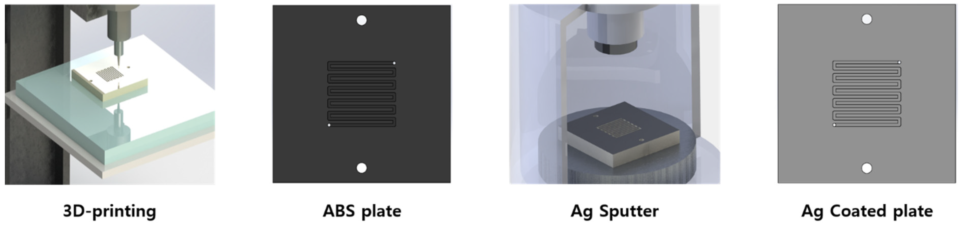
Figure 2 presents the schematics of the fabrication processes. As shown in
Figure 2, a commercial 3D printing system (F170, Stratasys, Eden Prairie, MN, USA) and conventional acrylonitrile-butadiene-styrene (ABS) filament were used to manufacture 3D-printed polymer bipolar plates. These 3D-printed polymer bipolar plates had serpentine-type flow channels with a 1.0 mm width and a 0.8 mm depth. After the preparation of the polymer bipolar plates, Ag current collecting layers were deposited on top of the bipolar plates using a commercial sputtering system (A-tech, Incheon, Korea). For the Ag sputter process, 200 W of direct current power was applied to the Ag target (diameter 2 inches, thickness 4 mm, 99.9%, RnD Korea, Gwangmyeong, Korea) at 0.67 Pa of Ar pressure (99.999%, Shinjin gas, Siheung, Korea). To investigate the effects of the thickness of the Ag current collecting layer for ultra-light PEMFCs, the thickness of silver current collecting layers was systematically controlled during the sputtering process.
Electrochemical properties of PEMFCs, such as open circuit voltage (OCV), current density–voltage curve, and electrochemical impedance spectroscopy (EIS) were investigated using a commercial potentiostat (SP-150, Biologic, Grenoble, France) with a current booster (VMP3B-10, BioLogic, Grenoble, France) to investigate effects of the thickness of the Ag current collecting layer. EIS measurement was carried out with the sinusoidal frequency range from 200 kHz to 0.1 Hz at various voltages. All electrochemical measurements were conducted at 25 °C. The weight of the bipolar plates was measured using a commercial scale (HS224S, Hansung, Gwangmyeong, Korea). Other components of the PEMFCs, except for the bipolar plates, such as end plates, GDLs, gaskets, MEAs, bolts, etc., were identical for all fuel cells. After the experiments using 3D-printed polymer bipolar plates, the morphology and thickness of the Ag current collecting layers were carefully evaluated by a scanning electron microscope (SEM, S-5200, Hitachi, Tokyo, Japan) to confirm the effects of the thickness of the silver current collecting layer.
3. Results and Discussions
After the fabrication of the bare bipolar plates and the deposition of the Ag current collecting layer, the weights of the Ag-coated bipolar plates were measured. The results are summarized in
Table 1. As shown in
Table 1, the total weights of bipolar plates including silver current collecting layers were not changed significantly. The total weight of the 3D-printed bipolar plates was changed from 34.79 g to 34.89 g (0.29% increased) when the average thickness of the silver current collecting layer was changed from 216 nm to 1.46 um. In particular, the weight of Ag-coated bipolar plates deposited for 4 min 30 s was very similar compared to bare bipolar plates. Assuming perfect conformality and uniformity of the silver current collecting layer, the theoretical volume of a 216 nm-thick silver current collecting layer is 0.777 mm
3, and the weight of a 216 nm-thick layer of Ag is 0.0082 g. Therefore, the measured same weight between the bare bipolar plate and the Ag-coated bipolar plate (4 min 30 s) was reasonable. Using the weight of the bare 3D-printed polymer bipolar plate, the density of the 3D-printed polymer bipolar plate was calculated to 0.982 g/cm
3. This is 8.22% lower than the theoretical density of ABS (1.060~1.080 g/cm
3) because of the inherent properties of the fused deposition modeling 3D printing process. Generally, the density of the bipolar plate is important because of gas leakage (usually hydrogen), which causes lower OCVs of fuel cells (usually lower than 0.8 V).
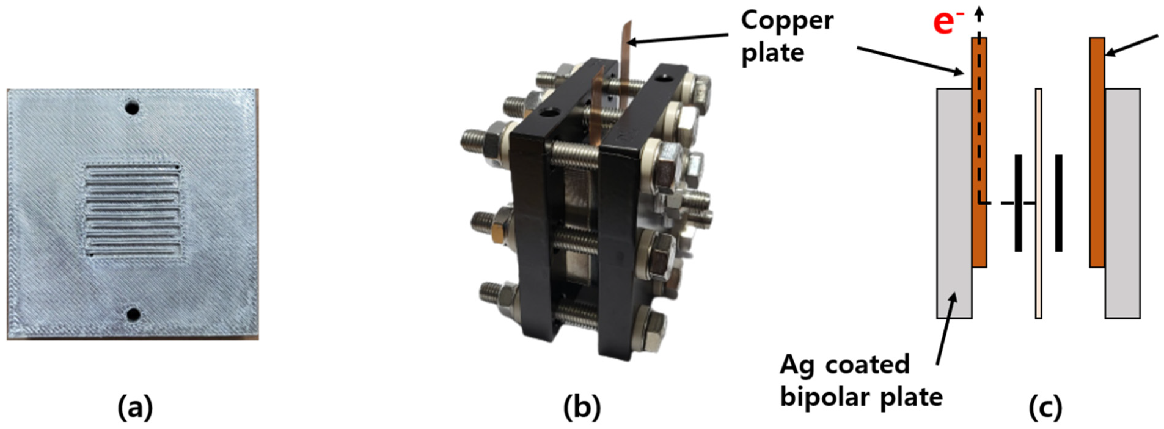
Figure 3 presents a Ag-coated bipolar plate, assembled unit PEMFC, and schematics of a fuel cell with silver-coated bipolar plates. As shown in
Figure 3b,c, electrons which were generated by electrochemical reactions flowed through the Ag layers on the polymer bipolar plates and were collected by the copper plates. In addition, the OCVs of fuel cells with Ag-coated bipolar plates were measured through the copper plates.
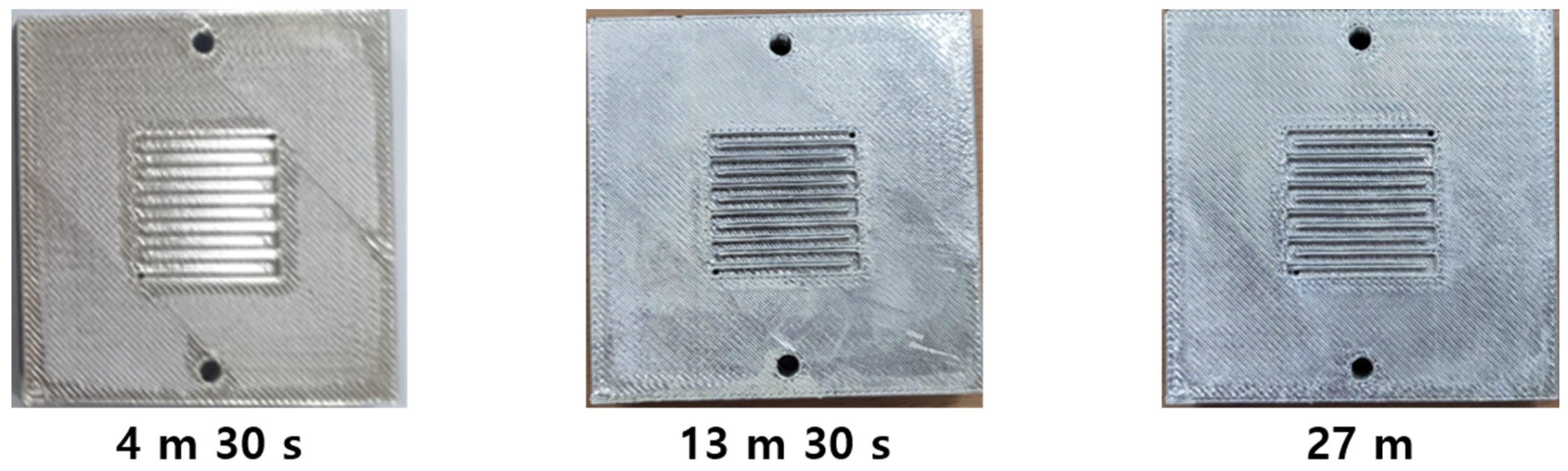
In
Figure 4, pictures of bipolar plates are presented. As shown in
Figure 4, we used Ag current collecting layer-coated 3D-printed polymer bipolar plates with different thicknesses for experiments. There are clear unique patterns in 3D-printed polymer bipolar plates because of the inherent characteristics of the FDM-type 3D printing process [
14]. In spite of the different thicknesses of silver current collecting layers, this pattern is clearly observed after the Ag current collecting layer deposition using a sputter process. This rough and patterned surface is caused by the unique film growth characteristics of sputter. In general, the morphology of thin films deposited by the sputtering process is significantly dependent on properties of the substrate such as roughness, porosity, pattern, etc. Therefore, in this report, patterns on the surface of the Ag current collecting layers originated from the patterns of the 3D-printed bipolar plates. Additionally, there was no clear evidence of macroscale defects in the silver current collecting layers which were well deposited on the 3D-printed polymer bipolar plates. This implies that the deposition of the silver current collecting layer by sputter was successfully conducted.
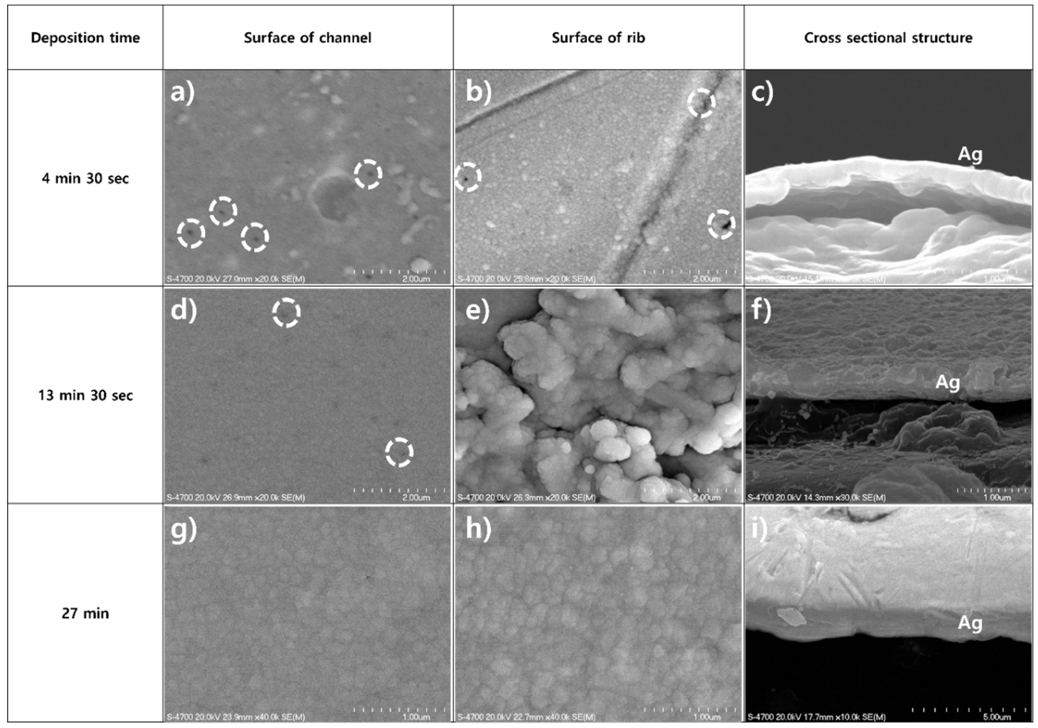
It is generally known that electrochemical reactions occur at triple phase boundaries (TPBs) where the gas, catalyst, and electrolyte exist [
1]. Thus, electrons are generated at TPBs and conducted through the electronic conductor (i.e., Pt and carbon in Pt/C catalyst) to the ribs of the bipolar plates of PEMFCs. Electrons then flow through the ribs to the current collector of the fuel cells. This implies that the quality of the Ag current collecting layer (i.e., physical and chemical defects) on top of the ribs in polymer bipolar plates is crucial. Therefore, detailed morphology investigations and cross-sectional structure measurements were performed on top of the rib of 3D-printed bipolar plates after experiments. In addition, the surfaces of channels were investigated to compare the effects of the experiments. The morphology and cross-sectional images of silver current collecting layers of 3D-printed bipolar plates are presented in
Figure 5. As illustrated in
Figure 5, the morphology of Ag current collecting layers was measured on top of the rib to confirm the surface defects caused by the inherent patterns of 3D-printed polymer bipolar plates. In addition, cross-sectional structures of the silver current collecting layers were analyzed on top of the rib. In general, defects in the current collecting layer significantly affected the electrochemical performance and characteristics of fuel cells because physical or chemical defects generate severe increments of ohmic resistance during fuel cell operation. Unlike
Figure 4, microscopic surface investigation revealed some defects in the silver current collecting layer. Defects are highlighted by white circles in
Figure 5. Interestingly, as the thickness of the Ag current collecting layer was increased, i.e., deposition time was increased, surface defects were decreased. It is generally known that the size of grains increases as the thickness of the film is increased, fabricated by physical vapor deposition. Thus, there were no clear defects in the silver current collecting layer deposited for 27 min (
Figure 5g,h). Additionally, the size of the grains, which was shown at the surface, was much larger in
Figure 5h than in
Figure 5b.
Electrochemical characteristics and performance of fuel cells are illustrated in
Figure 6.
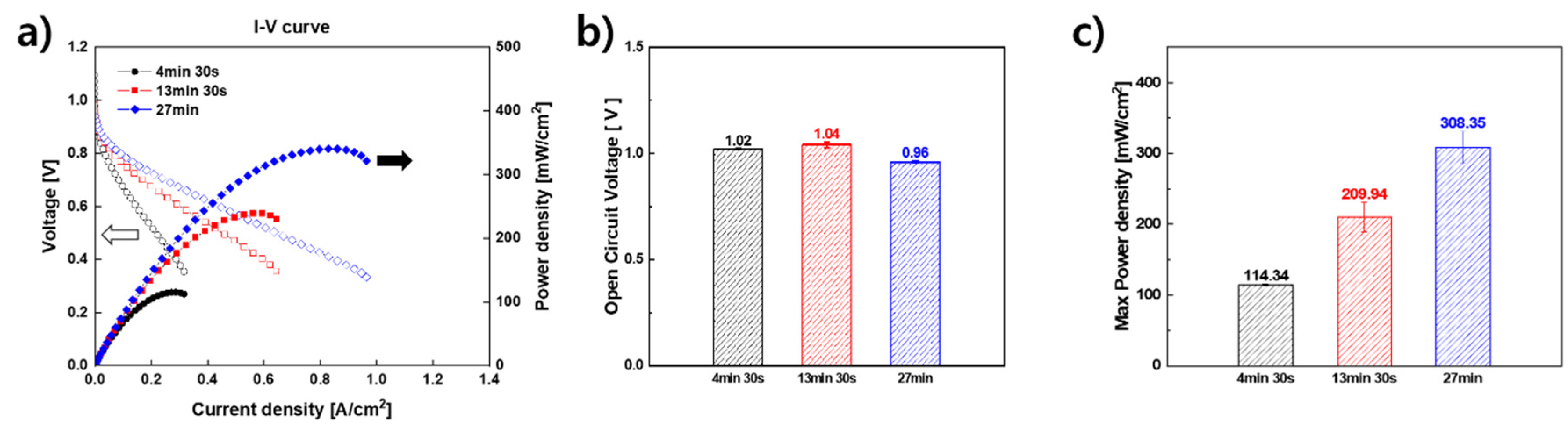
Figure 6a shows current density–voltage curves of PEMFCs using 3D-printed bipolar plates with different thicknesses of Ag current collecting layers. It is widely known that the slope of the polarization curve implies the total ohmic resistance of a fuel cell [
1]. In addition, the total ohmic resistance of a fuel cell is significantly affected by the current collecting method. As shown in
Figure 6a, the slope of the current density–voltage curve shows a strong relation to the thickness of the Ag current collecting layer on top of the 3D-printed polymer bipolar plates. As we mentioned before, all components of fuel cells such as MEA, GDL, gaskets, and end plates were identical for all fuel cells except the thickness of the silver current collecting layers of the bipolar plates. Additionally, the torque of bolts, which had clear effects on the ohmic resistance of a fuel cell (i.e., contact resistance), was maintained [
15]. This means that the thickness of the current collecting layer of the 3D-printed polymer bipolar plate was the main reason for the different ohmic resistances of the fuel cells. In other words, the thin current collecting layer caused a higher total ohmic resistance in the fuel cells because of the reduced area of the current path; therefore, the performance of the fuel cells was dramatically decreased.
Notably, the OCVs of all fuel cells were measured over 0.9 V despite the relatively lower density of polymer bipolar plates. As shown in
Figure 6b, the OCVs of fuel cells were measured at 1.02 V, 1.04 V, and 0.96 V for 216 nm, 473 nm, and 1.46 um thicknesses of the current collecting layer, respectively. The measurement of 0.96 V using a 1.46 um-thick Ag current collecting layer cell was relatively lower than other OCVs. However, a number of prior studies showed around 1.0 V of OCVs [
2,
3,
5,
6,
7,
16,
17,
18,
19,
20]. This is because of the inherent hydrogen permeability of Nafion
®, PTFE gaskets, etc. Therefore, in this study, the reasonable OCVs of all fuel cells mean that there were no critical problems related to sealing. Interestingly, as shown in
Figure 5, 216 nm-thick and 473 nm-thick silver current collecting layers had some surface physical defects. However, OCVs of fuel cells mean that surface defects observed by SEM analysis were not affected by gas tightness. In
Figure 6c, relations between the thickness of current collecting layers and the performance of fuel cells are illustrated. As the thickness of the Ag current collecting layer was increased, the performance of the PEMFC was improved. The average maximum power densities of PEMFCs that were achieved are 114.34 mW/cm
2, 209.94 mW/cm
2, and 308.35 mW/cm
2 when the thickness of the silver current collecting layer was changed to 216 nm, 473 nm, and 1.46 um, respectively.
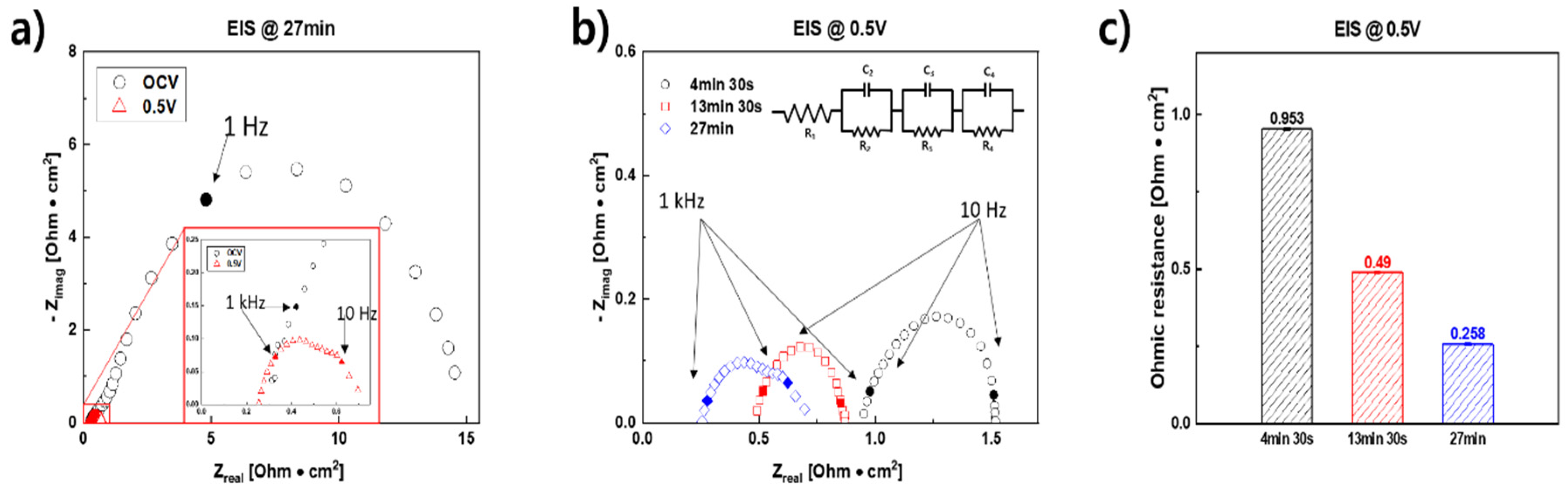
To evaluate the detailed electrochemical characteristics of fuel cells, EIS measurements were conducted for the fuel cells. Generally, the
x-axis intercept point in the high-frequency region implies the total ohmic resistance of the fuel cells [
1]. In addition, the diameter of the semi-circle shown at the low-frequency region represents the total faradaic resistance of the fuel cells [
1]. Moreover, the total ohmic resistance (i.e., the
x-axis intercept point) is maintained in spite of different biased voltages. However, the total faradaic resistance (i.e., the diameter of the semi-circle in the low-frequency region) is strongly changed as the measured voltage is varied [
1]. Thus, as shown in
Figure 7a, the total ohmic resistance of PEMFCs and the total faradaic resistance of fuel cells with 3D-printed bipolar plates were clearly classified.
Figure 7b presents the EIS results of all the fuel cells measured at 0.5 V.
Figure 7c summarizes the total ohmic resistances of the fuel cells. Similar to the current density–voltage curves in
Figure 6a, the total ohmic resistances of the fuel cells were significantly affected by the thickness of the current collecting layers. The ohmic resistance of a PEMFC was decreased, as the thickness of the silver current collecting layer was increased. Interestingly, it seems like the total faradaic resistance of fuel cells shows some correlations to the total ohmic resistance of PEMFCs. As we mentioned above, electrochemical reactions occur at TPBs where the gas, catalyst, and electrolyte meet. For TPBs, catalysts (usually metals) take charge of electronic conduction. The small faradaic resistance of a fuel cell means that steps in electrochemical reactions are smoothly processed with minimized interruptions. There are lots of important factors for smooth electrochemical reactions, such as low activation energy, highly activated catalysts, low ohmic resistance of electrolytes, etc. [
1]. Among them, sufficient supply of electrons, gas molecules, and ions are crucial for smooth electrochemical reactions. A lack of gas molecules, ions, and electrons cause both severe mass transport resistance and faradaic resistance because of a starvation of fuels (oxygens) [
1]. From this point of view, PEMFCs with thin Ag current collecting layers of 3D-printed polymer bipolar plates could not supply enough electrons to TPBs in MEA because of the thin current collecting layer. As we mentioned before, a thin current collecting layer means a small area of electron conduction. Thus, similar to the total ohmic resistance of fuel cells, the total faradaic resistance of PEMFCs was significantly decreased as the thickness of the silver current collecting layer was increased (i.e., diameters of semi-circles in low frequency region were increased).


