
Radio Frequency Fingerprint-Based DSRC Intelligent Vehicle Networking Identification Mechanism in High Mobility Environment

1
School of Information Science and Engineering, Southeast University, Nanjing 210096, China
2
The Purple Mountain Laboratories for Network and Communication Security, Nanjing 211111, China
3
State Key Laboratory of Mobile Communication, Southeast University, Nanjing 210096, China
4
School of Cyber Science and Engineering, Southeast University, Nanjing 211189, China
5
Key Laboratory of Computer Network Technology of Jiangsu Province, Nanjing 210096, China
*
Author to whom correspondence should be addressed.
Sustainability 2022, 14(9), 5037; https://0-doi-org.brum.beds.ac.uk/10.3390/su14095037
Submission received: 18 March 2022
/
Revised: 10 April 2022
/
Accepted: 20 April 2022
/
Published: 22 April 2022
(This article belongs to the Special Issue Emerging Technologies for Sustainable Intelligent Cooperative Vehicle-Infrastructure Transportation Systems)
Abstract
:In recent years, Dedicated Short-Range Communication (DSRC) vehicle interconnection technology has achieved mature development and broad applications, which is the key Vehicle to Everything (V2X) technology to realize transport intelligence. However, the openness of wireless transmission and the mobility of wireless terminals cause the identification mechanism of the DSRC system to face serious security threats. A radio frequency fingerprint (RFF)-based identification method can better resist the identity attack and spoofing by extracting the hardware characteristics formed by the differences of electronic components to authenticate different devices. Therefore, in this paper a novel RFF identification mechanism is proposed for IEEE 802.11p protocol-based DSRC intelligent vehicle networking devices suitable for a high mobility environment, in which the preamble field features of physical layer frames are extracted as device fingerprints, and the random forest algorithm and sequential detection method are used to distinguish and authenticate different devices. The experiment and simulation results demonstrate that the identification accuracy rates of the eight DSRC modules in the low-speed LOS and NLOS experimental states and up to 70 km/h high-speed simulations all exceed 99%, illustrating that this method has important application value in the field of identity authentication of V2X devices in high-speed scenarios.
1. Introduction
The interconnected vehicle technology is an effective method to solve the information intercommunicating problems in the intelligent transportation system (ITS) and plays an important role in the sustainable development of intelligent transportation [1]. Among them, Vehicle to Everything (V2X) is one of the key interconnected vehicle technologies for realizing ITS, and the ultimate goal of V2X is intelligent transportation. The communication mode of V2X includes various forms of interaction between vehicles and surrounding vehicles, vehicles and road infrastructure, vehicles and Internet cloud service platforms, vehicles and roadside pedestrians, etc. The V2X system contains a variety of elements, which requires the cooperation of the communication industry, the transportation industry, the automotive industry, the electronics industry, and the cyber security industry to jointly build a novel technology and business model [2].
In the global V2X system which provides interconnected vehicle services, there are two main technical routes, Dedicated Short-Range Communication (DSRC) and Cellular-V2X (C-V2X). DSRC is an in-vehicle communication standard based on the IEEE 802.11 wireless local area network protocol, while C-V2X is a cellular communication V2X standard technology based on 4G Long Term Evolution (LTE) and 5G New Radio (NR).
C-V2X technology appeared slightly later than DSRC, whereas its development is relatively rapid, and its performance is more stable than DSRC. However, DSRC has a greater advantage in terms of industrial maturity [3]. Based on sophisticated Wi-Fi technology, DSRC technology has been widely used in access control, fleet management, electronic toll collection (ETC) system, and other fields, with more frequent interactions and up to 10 times exact broadcast information per second including vehicle position, speed, and acceleration. With limited mobility and low vehicle density, DSRC can provide end-to-end latency of less than 100 ms and throughput equivalent to 10 kbps [4]. A large number of trials have been carried out globally on 802.11p-based DSRC 2.0 from 2009 to 2021 in preparation for large-scale commercialization [5].
However, due to the openness of the wireless network transmission medium and the mobility of terminals, there are certain security problems and uncertainties in the communication process of the V2X system [6], which may lead to the possibility of eavesdropping, forgery, or replay of information exchanged between vehicles. If the communication system is hijacked and erroneous instructions are issued, it will bring serious security risks to vehicles, personnel, and roads. Therefore, the identification and access control of wireless devices in the V2X systems is particularly important.
In view of the current security threats in the V2X systems, the proposed secure communication models and identification technologies include: utilizing the blockchain-based multi-factor authentication models to enhance identification mechanism [7]; using the elliptic curve encryption-based digital signature scheme to strengthen the safe interaction of V2X data information [8]; security authentication between cross-layer and cloud platforms based on cryptographic algorithm technology such as national secret algorithm [9]; utilizing various access security mutual trust authentication protocols simultaneously integrating 5G technology for secure communication of the Internet of Vehicles [10]; using third-party security modules such as cloud servers and certificate servers to authenticate users to protect the confidentiality and integrity of information [11]; etc.
The above-mentioned traditional identification and access control protocols are mainly based on cryptographic mechanisms, most of which run above the data link layer. Once the key is leaked, the network security cannot be guaranteed. Further, the third-party server authentication-based identification methods need to consume additional resources and increase the power consumption and complexity of the system [12], which makes it difficult to achieve non-perceptual authentication. In recent years, wireless communication network security has begun to rely on the physical layer security technology, and the use of non-cryptographic identification mechanisms can achieve better performance against identity attacks compared to traditional authentication methods [13], which may be the future development trend of user identification technology of V2X systems [14]. In the field of physical layer security, radio frequency fingerprint (RFF)-based identification technology is one of the current researching hot directions, which identifies and authenticates each wireless device individual by extracting the hardware characteristics that are unique and difficult to clone. Therefore, in this paper an RFF-based V2X identification and authentication mechanism is explored and put forward for the DSRC technology based on the IEEE 802.11p protocol, which can also achieve better recognition results in the scene of moving vehicles.
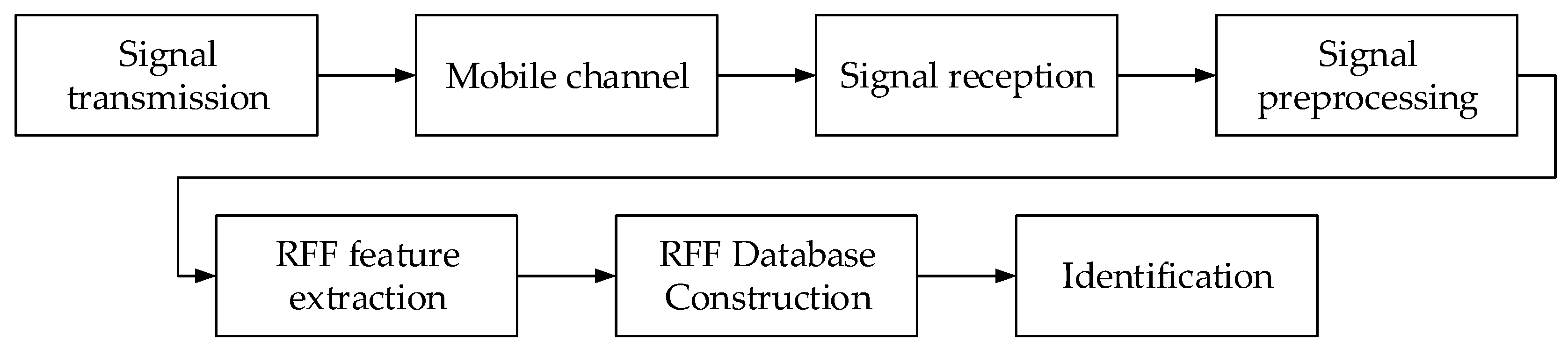
The flow chart of RFF extraction and identification process for DSRC intelligent vehicle networking is shown in Figure 1. After the DSRC device to be identified sends out the signal, the signal is collected by the receiver after passing through the mobile channel. When the signal preprocessing is completed, channel characteristics and other environmental interference factors are removed and only the RFF characteristics of the device itself are retained. Subsequently, the feature extraction of RFFs, the design of classifiers, the training and registration of fingerprint database, and the identification and authentication process are carried out in sequence.
The structure of this paper is organized as follows. The second section reviews the related studies in the previous literature and lists the contribution of this paper. The third section introduces the IEEE 802.11p protocol standard and describes the signal acquisition and preprocessing process. The fourth section presents the novel radio frequency fingerprint extraction and identification methods valid in complex mobile environment. The fifth section introduces the experiment and analyzes the results. The final section summarizes the research work done in this paper.
2. Related Works
The transmission information of the physical layer in the wireless communication system, which is at the bottom of the OSI network layer, contains some characteristics that cannot be reflected in the data transmission process from the upper layer. Therefore, the identification and authentication technology based on radio frequency fingerprints takes advantage of the unique hardware features of the devices which can be reflected in the physical layer to distinguish different users, aiming at improving the security level of information transmission. Radio frequency fingerprint is the hardware characteristic of the device, which can be understood as the DNA of the device itself. There are certain differences in the electronic components of the transmitting signal circuit between each wireless device, so that each wireless transmitter will produce different radio frequency response parameters when performing radio frequency work, and ultimately lead to different radio frequency fingerprints produced by different devices [15]. Radio frequency fingerprint mainly has five characteristics: universality, uniqueness, short-term invariance, independence, and robustness, which is not affected by channel and location variation. In the process of feature extraction and recognition, the hardware structure of the original system does not need to be changed [16], and its normal operation is not affected; thus, non-perceptual authentication and recognition can be realized. Moreover, the hardware characteristics of the devices are difficult to clone, which brings higher attack cost and better anti-attack performance.
In the more than 20 years of development of radio frequency fingerprint identification technology, scholars have achieved a variety of RFF extraction and recognition methods through research. The research of RFF identification has experienced the transformation from using transient signals to using steady-state preamble field sequences, and then to using arbitrary data field information; from the use of single domain features to the use of multi-domain features, and from the waveform domain-based methods to the modulation domain-based methods; from the use of supervised learning to unsupervised learning, and then to deep learning methods [17].
Most of the early research on RFF focused on transient characteristics, which extract the instantaneous amplitude, instantaneous frequency, signal envelope, and phase information by detecting the transient signal [18]. In recent years, more researchers have turned to the feature extraction of steady-state signals, such as stable preamble signal, to achieve more recognizable steady-state RFF features. Initially, Kennedy et al. [19] proposed that they converted the steady-state preamble signals to spectral features as radio frequency fingerprints based on frequency domain characteristics to identify user equipment in the universal mobile telecommunications system. Afterwards, Wheeler et al. [20] extracted the carrier frequency offset value from the preamble of the IEEE 802.11a Wi-Fi signal and studied the effect of using or removing the frequency offset on RFF recognition.
In addition, RFF feature extraction and recognition can also be carried out in the waveform domain and modulation domain. In terms of waveform domain, Williams et al. [21] have shown through experiments that the fingerprint recognition performance can be improved from the time domain to the wavelet domain and the spectral domain. While in the modulation domain, the feasible features include carrier offset, modulation offset, I/Q offset, power amplifier nonlinearity, constellation trace figure, and so on. Peng et al. [22] proposed an RFF extraction and device classification scheme that mixes multiple modulation features. Within this hybrid method, extensive experiments were conducted to prove the effectiveness of classifying a large number of devices under different channel conditions including line-of-sight (LOS) and non-line-of-sight (NLOS) scenarios and to verify that the extracted RFF features are still stable and invariable after one and a half years.
In the past decade, many studies have applied classifiers to RFF identification. Designing classifiers for machine learning can improve generalization ability, which is the key processing step after extracting RFF characteristics. The existing mature methods for RFF classification include Bayesian classification algorithm, K-nearest neighbor algorithm, neural network classification algorithm, support vector machine classification algorithm, random forest algorithm, etc. In addition, deep learning methods that have demonstrated excellent performance in image recognition, voice recognition and other fields can also be applied to RFF recognition, such as using the framework of deep neural network to detect the extracted fingerprint features [23].
For different kinds of signals and modulation modes, different multipath channels and environmental interference, and different signal-to-noise ratios, the researchers also put forward some novel improved methods to optimize the RFF identification rate. For example, according to ZigBee signals, Zhou et al. [24] proposed an algorithm for long-term stacking of repeated symbols to convert the measurement noise into standard Gaussian distribution, and another algorithm for artificially adding noise in the training stage to improve the performance under time-varying channels. Their further study reveals that the scheme is feasible and robust in additive white Gaussian noise channel and multipath scenarios. For linear frequency modulation (LFM) radar signals, Xing et al. [25] put forward a radio frequency fingerprint identification mechanism, which performs the signal derivation and envelope operations to extract both transient-based and modulation-based features after the interference pulses are eliminated through the piecewise curve fitting-based denoising algorithm. For GSM communication standard mobile phones, Wang et al. [26] combine the physical layer RFF method of differential constellation trace figure with the classification scheme of convolution neural network, which can identify different devices with low complexity and high accuracy and can still possess strong robustness when the device locations and GSM parameters change.
From the above analysis, it can be seen that the research on radio frequency fingerprint identification has made significant progress, which is still a hot topic. At the same time, there are some deficiencies and challenges in the current research, and the following issues remain to be further explored for practical application in the V2X intelligent transportation systems. First, the influence of time-varying wireless multipath channels on the stability of RFF has not been emphatically discussed in the past. Since the vehicles are in a high-speed moving state in the actual DSRC vehicle networking environment, the received signal strength indication (RSSI) and channel state information (CSI) values are constantly changing, which cannot be used as device fingerprint features. Previous studies on RFFs mostly considered the ideal static situation and did not take into account the diversity of transmission channel in the mobile environment and the interference caused by other obstacles. The extracted device fingerprints are often mixed with channel fingerprints, which will change with the location, and the RFF identification accuracy will decrease once in a mobile environment. Second, the 802.11p protocol signal in DSRC is a broadband signal with a bandwidth of 10 MHz, which carries abundant spectral information and is more susceptible to the multipath interference caused by people walking, wall and obstacle reflections, and other negative factors in complex indoor environment. Therefore, previous traditional RFF methods for narrowband signals are not applicable.
In view of the above problems and shortcomings, this paper further studies the IEEE 802.11p protocol-based DSRC intelligent vehicle networking radio frequency fingerprint extraction and identification technology in high-speed mobile environment. The main contributions of this article are listed as follows:
- A novel RFF extraction method is proposed for the IEEE 802.11p preamble signal, which utilizes the ratio of the spectrum amplitudes of the superimposed short training sequence and long training sequence as the fingerprint feature. This method can effectively remove the channel interference and is less affected by noise and position movement, thus obtaining more stable device fingerprints.
- The random forest algorithm and sequential detection method are discussed to classify and identify RFF features, which adapt to the complex and changeable mobility environments and can improve the accuracy of recognition.
- For eight modules of the same model that can transmit IEEE 802.11p protocol signals, experiments are carried out in static state, indoor LOS moving state and partition NLOS moving state, and simulation are tested in a vehicle speed of 0–70 km/h to corroborate the stability and fine recognition performance of the extracted device RFF features in high mobility scenarios. After completing the signal acquisition and feature extraction, the identification accuracy rate of more than 99% can be achieved through the above classification and identification algorithm.
3. Signal Acquisition and Preprocessing
3.1. IEEE 802.11p OFDM PHY Frame
As mentioned above, the radio frequency fingerprint-based identification method belongs to the research scope of physical layer security. Therefore, the physical layer (PHY) specification in the IEEE 802.11p protocol standard [27], which is used as the underlying technology by DSRC, is first introduced in this section. The IEEE 802.11p standard specifies the PHY entity for an orthogonal frequency division multiplexing (OFDM) system [28], in which the orthogonal subcarriers can be overlapped together without affecting each other, with strong anti-interference ability and high spectrum utilization. In this OFDM system, the frame format of the Physical Layer Convergence Procedure (PLCP) Protocol Data Unit (PPDU) is defined, which is composed of a preamble field, a signal field, and a data field, including the OFDM PHY preamble, the PHY header, the PLCP Service Data Unit (PSDU), the tail bits and the pad bits.
In the PPDU encoding process, it contains multiple steps such as producing the preamble field, adding a guard interval, filling corresponding bit fields, calculating relevant parameters, and inserting pilots. The service bits, whose length is stored in the length field of the PHY header, together with the PSDU, are part of the data field. In addition, the data transmission rate, modulation mode, and coding rate are determined by the rate field of the PHY header in the signal field. Therefore, the content of both the signal field and the data field will change according to the data content actually transferred and transmission rate. However, the data format transmitted in the preamble field is constant, hence it is more feasible to extract stable and invariable RFFs from the PHY preamble field.
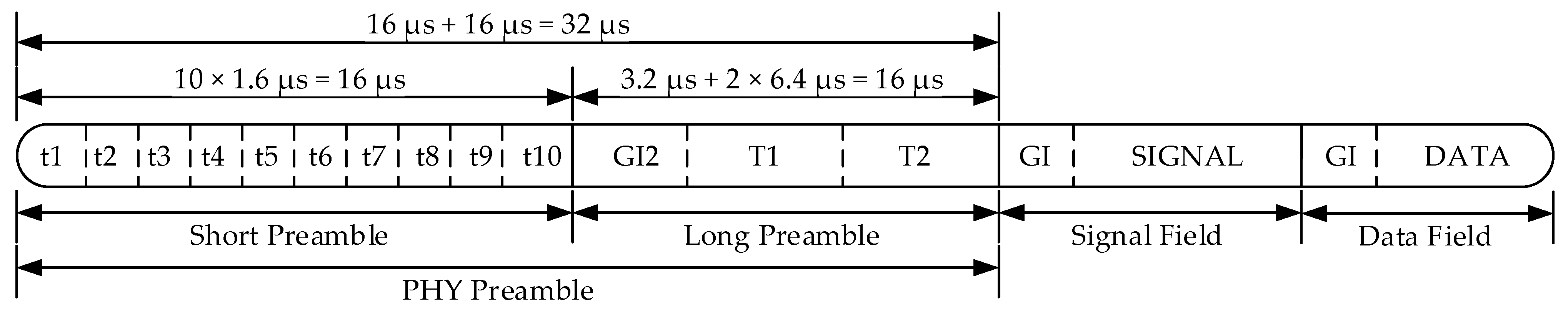
The OFDM PHY preamble field contains 10 repeated short training symbols and 2 repeated long training symbols, and its main function is to realize signal synchronization. Figure 2 shows the training structure of PHY preamble in the IEEE 802.11p OFDM PPDU frame format, where t1 to t10 represent short training symbols and T1 and T2 represent long training symbols. At 10 MHz channel spacing, the total preamble training duration is 32 µs. These cyclic repeated symbols are caused by the periodicity of the inverse Fourier transform, and the period of a Fourier transform or inverse Fourier transform TFFT is 6.4 µs [29].
The structures of short training symbols and long training symbols are different. A short training symbol consists of 12 subcarriers, which is modulated by the elements of sequence
Since the short training symbol only utilizes 12 of the 52 subcarriers, and its spectrum only has a non-zero spectral amplitude at a multiple of 4, the signal period of the short training symbol is one quarter of that of TFFT, i.e., 1.6 µs. There are 10 such training symbols in the short preamble field, with a total duration of 16 µs.
A long training symbol consists of 53 subcarriers, including a DC zero value, which is modulated by the elements of sequence
A period of long training symbol lasts 6.4 µs in the time domain, and the protocol states that two periods of long training symbols need to be sent, totaling 12.8 µs. In addition, a 3.2 µs cyclic prefix GI2 is added before the two long training symbols with the result that the total duration of the long preamble field is also 16 µs.
Each frame of PPDU signal has the same format of preamble field, and the short preamble and long preamble have the same length and different structures, which is convenient for the removal of channel features and the extraction of the location independent RFF characteristics with better consistency.
3.2. Signal Acquisition
Wireless signals are often collected through universal software radio peripheral (USRP). After the wireless signals are collected, it is necessary to capture and separate each frame conforming to the OFDM PPDU frame format from the collected signals for subsequent analysis, and at the same time the interference of other standard signals that may exist in the air should be also considered.
Considering that the PHY preamble has a fixed repetition structure, and especially the time domain waveform of 10 repeated short training symbols has obvious distinction, which can be used as the search target for fast acquisition, the method of cross-correlation operation with the local ideal signal can be adopted to realize the signal capture. Since the real-time requirement for capturing valid signal frames from the received signals needs to be satisfied in practical work, the way of sliding a small window to receive the signal can be taken, in which the collected signal is sent to the processor in sequence, and its conjugate correlation value is calculated with a local ideal short training symbol. If the correlation value exceeds the threshold value and the energy of the received signal also exceeds the threshold value, it can be considered that the signal acquisition is successful.
In the IEEE 802.11p protocol, a short training symbol lasts for 1.6 µs and occupies 32 sampling points at a sampling rate of 20 MHz. Using a window with a length of 32 sampling points for sliding and performing correlation operations have low overhead and can basically meet the demands of real time. Suppose a local short training symbol is , and the received signal taken out by sliding window and sent to the processor is . In order to facilitate the comparison with the decision thresholds, the amplitudes of the two sequences are normalized first. The two normalized sequence signals are
where , L denotes the sampling points of a short training symbol. The complex conjugate correlation value of two normalized signals is expressed by
where is the conjugate of . Only when the calculated value exceeds the threshold , can it be considered that a short training symbol has been captured. In addition, since the correlation value of the noise part after the normalization may also exceed the threshold, the energy of the received signal itself
also needs to exceed a threshold value. According to the above acquisition rules, when the correlation values of continuous multi-segment signals with local ideal signal and their own energy both exceed the threshold, it means that a frame of IEEE 802.11p PPDU signal has been acquired.
3.3. Signal Preprocessing
Before extracting the RFF features, it is necessary to preprocess the captured PPDU frames, which mainly includes time synchronization and frequency offset compensation.
In the previous signal acquisition step, the starting position of each frame is only roughly determined, which may have a certain time deviation from the actual signal start point. While in the process of frequency offset compensation and fingerprint extraction, there is a high requirement for the accuracy of time synchronization. Therefore, in this section an improved synchronization method is proposed based on the existing method, in which the short preamble is utilized for coarse synchronization first, and then the long preamble is utilized for fine synchronization. Both the coarse synchronization and the fine synchronization are realized by performing complex conjugate correlation operation between the received signal and the corresponding local preamble signal, which can make synchronization more precise through two correlation operations.
Due to the strong correlation of short preamble, it is first used for coarse synchronization. During the correlation operation for each PPDU frame, the complete 16 µs short preamble field is used, and the range of M sampling points before and after the starting point determined by the acquisition process are contained to ensure that the actual starting point is included in this range. Assume that the local ideal short preamble signal is , and the received signal is , whose energy normalized complex conjugate correlation value is
where
, M denotes the sampling points before and after the starting point determined during signal acquisition, , N denotes the sampling points of a short training symbol. The position is the starting point of the coarse synchronization of each frame where the maximum value is obtained by
However, in the case of severe multipath channels and mobile environment, the peak point performed by correlation calculation in the coarse synchronization process may have several points deviation. Therefore, it is necessary to use the long preamble field for fine synchronization. The fine synchronization utilizes the 16 µs long preamble field for correlation operation, whose sliding searching range is within 3.2 µs before and after the starting point determined by the coarse synchronization, namely a total of 6.4 µs, which is the length of a long training symbol, and the correlation operation method and calculation equations are similar to the coarse synchronization process.
The frequency offset is mainly caused by the inconsistency of the frequency between the wireless signal receiver and the transmitter oscillator. In the process of frequency offset compensation, the frequency offset values are estimated and then averaged through multiple periodic repetitive signals of the short preamble.
In the frequency offset estimation process, the phase offsets between the corresponding points of the two adjacent short training symbols are estimated, and then their average value is calculated. The 10 short training symbols can be used to calculate the phase offset between the adjacent symbols for 9 times, and finally the phase offset can be converted to the frequency offset. The specific calculation process of frequency offset estimation is as follows.
Assuming that is the nth sampling point of the ith ideal local short training symbol, is the nth value of the ith received signal of the actual short training symbol, and the frequency deviation of the transmitter and receiver is . By calculating the conjugate correlation value between the two adjacent short training symbols, the phase offset of the corresponding point between the ith and the (i + 1)th short training symbol can be expressed as
where , , L denotes the sampling points of a short training symbol, denotes calculating phase angle of complex number, and denotes the sampling interval. Then, the average of the phase offset of corresponding points between the adjacent short training symbol is calculated. Eventually, the average frequency offset produced by a sampling interval can be calculated by
where represents the sampling frequency of the receiver.
The frequency offset compensation process is performed on the overall preamble field signal after synchronization, and is implemented by
where is the signal after synchronization and is the signal after frequency offset compensation. This frequency offset estimation and compensation method can well remove the signal phase deviation caused by the frequency offset, and better serve the subsequent fingerprint extraction.
4. RFF Extraction and Identification Methods
4.1. Preamble Field-Based RFF Extraction Method
After the signal acquisition and preprocessing steps are completed, the features of the radio frequency fingerprint can be extracted. In the mobility environment, if stable RFFs need to be obtained, the most challenging problem to be solved is to eliminate the time-varying influence of the channel. This paper proposes an RFF extraction method for IEEE 802.11p-based DSRC signals, which utilizes the characteristics of the preamble field of the OFDM PHY frame, superimposes part of the time domain waveform of the short preamble and the long preamble, and then divides the spectrum of them to remove the multi-channel and the added noise in the mobile environment, resulting in a purer device fingerprint.
First, four signal sequences are taken out from the preprocessed OFDM preamble field in order to extract the fingerprint for each frame of received signal. Considering that the first short training symbol may be affected by the initial transient response, and that the IFFT transformation period is 6.4 µs, equivalent to four times of the period of the short training symbol, the second to fifth symbols are taken and named as the sequence STF1. Accordingly, the seventh to tenth symbols are taken as the sequence STF2. For local signal sequence, STF1 and STF2 are theoretically identical, each containing 12 subcarriers. For long preamble, regardless of the cyclic prefix part, the first long training symbol is taken as the sequence LTF1, and the second long training symbol is taken as the sequence LTF2. Theoretically, LTF1 and LTF2 are also identical, each containing 52 non-DC subcarriers. As described in Section 3.1, the four sequences are identical in length and each last for 6.4 µs, totaling 128 sampling points at a sampling rate of 20 MHz.
However, in practice, the preamble field signals transmitted by each device are not the same, because the RFF information of the transmitter will be parasitized in the signal it sends. In addition, when the transmitter sends the wireless signal, it will experience wireless channel and generate convolution relationship with the multipath effect in it. Moreover, the final received signal will be affected by various types of noise dominated by additive noise. The following part will discuss and deduce how the method proposed in this paper can not only preserve and enhance the RFF features, but also eliminate the mobile multipath interference and additive noise.
The formation of RFF can be ideally modeled as a local time domain baseband signal passing through a filter, in which the local ideal signal and fingerprint are in a convolution relationship, and the received signal can be expressed as
where , N denotes the length of the sequence. In the four signal sequences mentioned above, each sequence lasts 6.4 µs and thus N = 128 if the sampling rate is 20 MHz. Besides, denotes the received signal, denotes the local ideal signal, denotes the RFF of signal transmitter, denotes the RFF of signal receiver, denotes the multipath channels experienced by the sequence, denotes the additive noise, and denotes a linear convolution operation.
Specifically, the received signal of the four sequences STF1, STF2, LTF1, and LTF2 are represented as
Since the local signal and are the same sequence, the RFF generated by the transmitter and are also the same. Similarly, and are the same. It is assumed that the multipath channel characteristics experienced by each of the four sequences in a frame signal are the same. In general, the same receiver is used for signal reception in the system, so the influence of the receiver RFF on the received signal is also regarded as the same. Additive white Gaussian noise can be proved to be a stationary random process with zero mean and constant variance, hence all four sequences are random sequences.
Additive noise can be attenuated by signal superposition in time domain. Since the mean value of additive white Gaussian noise is zero, when enough noise sequences are added, the value of the stacked sequence is in theory zero, which proves that the method of superposition denoising method is feasible. In a frame of PPDU signal, the received two STF sequences and , and two LTF sequences and , can be added separately to enhance the fingerprint features and ease the influence of noise to a certain extent. Although only two sequences are superimposed each time, the fingerprint part is enhanced twice, and the amplitude of noise is reduced compared to the original.
In the V2X system using DSRC technology, the vehicle is moving at a high speed in most cases, and the relative position between the receiver and the sender is often changing, so that each frame of the received signal has a variable channel factor, which adversely affects the extraction of stable RFFs. By using the repeated preamble structure defined in the PPDU frame format of IEEE 802.11p standard, transforming the time domain signal into the frequency domain and applying the division operation can remove the interference of channel condition on the fingerprint.
After the above time domain superposition operations of STF and LTF, it can be approximately considered that the noise has been effectively eliminated. The expressions of the superimposed sequences transformed into frequency domain are
where , , , , are the frequency domain of , , , , , respectively. According to Equations (1) and (2), the amplitudes of the non-zero spectrum of short training symbol and long training symbol are different in the frequency domain. When the signals are transmitted with different amplitudes, the nonlinearity of the power amplifier in the transmitter will cause it to work in different states [30]. The difference in signal transmission power and energy will result in different nonlinear fingerprints generated by nonlinear electronic components such as power amplifiers. When the two identical STF sequences and two identical LTF sequences are transmitted, the frequency domain of transmitter RFF can be uniformly expressed as and , while these two fingerprint expressions are different. When the two parts receiving signals are divided in the following steps, even if the consistent linear part is removed in the division operation, the nonlinear RFF components can still be preserved.
Next, the frequency domain expressions of the two superimposed sequences are divided to remove the multipath channel, which can be shown as
where is the spectrum of the ideal signal and is a fixed value, the linear channel part and linear fingerprint part can be cancelled, and the nonlinear fingerprint part can still be retained. Therefore, the above Equation (21) can be further simplified to
where A denotes a constant value. It can be seen from the above Equation (22) that only the transmitter fingerprint feature is included, and the RFF expression is only related to the characteristics of the transmitter itself and has no relationship with the channel. Therefore, this expression can be used as the RFF feature expression in the mobile multipath environment.
The above-mentioned method of removing noise by superimposing the short preamble and long preamble in the time domain, and then removing the channel by division in the frequency domain has basically realized that the multipath effect and environmental noise interference of the wireless channel are eliminated only through the preamble field of the collected signal of one frame. At the same time, the pure RFF information of the device is preserved to the greatest extent.
4.2. Random Forest and Sequential Detection-Based RFF Identification Method
After the radio frequency fingerprint feature vectors of the devices are extracted according to the above method, the next step is to use these features to distinguish and identify different devices. In this paper, the random forest algorithm which has better effect in the machine learning methods is selected and combined with the sequential detection method to effectively distinguish devices of the same model and to better adapt to the diverse environment through long-term observation and tracking of the trend of RFF features.
The random forest algorithm is an ensemble learning algorithm that uses multiple decision trees to train samples and make judgments and the judgment results are obtained by the combination of multiple decision trees randomly generated in the forest [31]. Based on the bagging idea, through randomly selecting samples for training, and then randomly selecting the characteristics of different dimensions of the samples to become the branch and establish a decision tree, the correlation between different decision trees is reduced and the accuracy of the model is further improved. After multiple iterations, the trees will adaptively select better samples and characteristics for branching each time, making themselves perform more outstanding in the forest. The idea of an “out-of-bag estimate” is taken advantage of, in which a part of the samples in the training set is used for learning, where the selected samples will be put back into the training set for the next extraction, and the remaining part of the samples is used for predicting. In the random forest algorithm, the importance of each dimension of the feature in the tree is measured by changing the weight of the feature in the tree and comparing the change of the error rate of the test data before and after the change.
The concrete steps to classify radio frequency fingerprint features using random forest algorithm are as follows:
- Set the size of the training set as N, the tree number in the forest as , the number of iterations as K. For each tree, K groups of training sample sets with the size of N need to be randomly selected.
- Assuming that characteristic dimension of the sample is n, specify a constant m << n, and randomly select m dimensions from the n-dimension vector for each training set above.
- In the process of generating K groups of training set, the optimal characteristics are selected in each round of iteration. Then, the m-dimension characteristics are used to maximize the growth of each tree to obtain the model for each decision tree and the whole forest.
- Among the K classification models, the optimal random forest model is selected by using the idea of “out-of-bag estimation”. For the input test set data, the final classification result is given by synthesizing the decision results of each tree in the forest.
The correlation between sub-sample sets and the correlation between characteristics of sub-sample sets is random, which ensures that the decision tree does not need pruning and will not cause overfitting. In addition, using multiple trees for decision making can also avoid overfitting caused by noise that may be generated by a single decision tree. Experiments also demonstrate that the random forest algorithm has a high classification accuracy for radio frequency fingerprint features, which will be introduced in the next section.
On the basis of statistical learning, this paper applies the idea of sequential detection to RFF identification. Sequential detection can comprehensively make a decision based on the current real-time signal features and the characteristics observed in the previous period of time. This method can reduce the impact of instantaneous feature mutation on RFF recognition and can update and correct the features in the fingerprint database in real time, thereby improving the recognition accuracy of the devices in long-term work.
The flow of the radio frequency fingerprint identification method using the thought of sequential detection is as follows:
- First, the RFF features of devices and their statistical parameter sets are extracted to form the final feature vectors X, which are entered into the fingerprint database.
- Then, in the process of the signal collection and identification, the same length of signal is cut out from each frame newly collected, and its features are calculated in the same way to obtain the feature vector Y.
- Next, the feature vector Y is compared with the feature vectors X in the fingerprint database to calculate the similarity S. The similarity can be measured by correlation coefficient, Euclidean distance, Mahalanobis distance, etc.
- The feature vector of newly acquired signal frame whose similarity exceeds the threshold will be stored in the buffer area, indicating that this frame of received signal is subordinate to the devices in the database, and the buffered data will be used for the judgment of subsequent new frames. On the other hand, if the similarity does not reach the threshold, it means that this frame is exceptional data, which may originate from a non-registered device, and additional buffer area needs to be opened up to store it.
- The newly received frame data from the same device for the second time will not only be compared with the previously entered fingerprint database, but also with the data in the buffer area. With the increase of data in the buffer area, the judgment accuracy will correspondingly be improved. Furthermore, when the buffer area data reaches a certain amount, the stable feature vectors can be updated to the fingerprint database, so as to dynamically adjust the fingerprint feature vectors of the devices in the database.
Through the sequential detection method, the system can continuously track relevant RFF features, and observe and learn their long-term change rule. During the process of identification, the feature of the current signal is compared with the real-time updated fingerprint database and the buffer area data at the same time for better recognition. In the meantime, continuous observation can avoid misjudgment caused by accidental instantaneous fluctuation of RFFs. When there is anomalous difference in the occasional one frame of signal caused by external factors, whose similarity to the feature vectors in the database is lower than the threshold, it will be stored in the new buffer area separately. Afterwards, when the subsequent feature values return to the normal range, they will still be judged to the original device, which will not affect the final judgment result. Therefore, the radio frequency fingerprint identification method incorporating sequential detection can further improve the recognition rate of RFFs in the changeable mobility environment.
5. Experiment Results and Discussion
In the experiment the ESP8266 modules are emulated as communication modules in the DSRC technology and are used to simulate the signal transmission that conforms to the IEEE 802.11p protocol standard. By configuring the corresponding parameters, eight ESP8266 modules of the same model are set to client mode or AP mode to simulate Vehicle-to-Vehicle, Vehicle-to-Infrastructure, Vehicle-to-Network, and other various modes. Afterwards, the transmitted wireless signals are subsequently received by USRP.
The USRP model used in the experiment is USRP N210 produced by Ettus Research company. The USRP is connected to the computer through a Gigabit Ethernet port for the acquisition of IEEE 802.11p signals, and the computer is equipped with the UHD software driver for USRP, the open-source software defined platform GNU Radio, the compilation environment, etc. Then, the received wireless signals are preprocessed and the extraction and identification of RFF features are performed by MATLAB software.
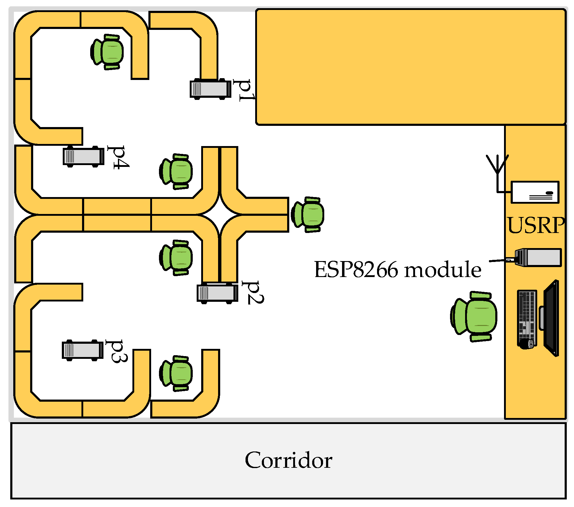
The experiment was carried out in a laboratory of 10 m × 9 m with a corridor outside it, and there is a wall between the laboratory and the corridor. The schematic diagram of the laboratory is shown in Figure 3. A number of tables, chairs and partitions are placed in the laboratory as obstacles, and the experiment modules can be moved inside and outside the laboratory, so that the wireless signal may be blocked from the process of transmitting to receiving by obstacles or walls, which can simulate the LOS and NLOS situations, as well as moving multipath scenarios.
During the experiment, the USRP is placed in a fixed position on the table shown in the figure, the ESP8266 module set to AP or client mode is placed near it, and another module that communicates with the module in the fixed position is placed on the mobile trolley. The experiment allows one or more modules to simultaneously communicate with the module in the fixed position on the table, and the USRP can collect the signals of several modules at the same time. In this experiment, the signals of the ESP8266 module are collected in three scenes of static state, indoor LOS moving state and partition NLOS moving state to test the RFF features extraction and recognition performance. The environment of the three experimental scenes and the placement or moving route of the communication module are described in detail as follows:
- Static state: The modules are placed at the four fixed static positions p1 to p4 marked in Figure 3. The distances between these four positions and the USRP are different, hence the received signal strength and the signal-to-noise ratios in each position are also different. At some points, there are obstacles in the path between the USRP and the transmitting modules with rich channel multipath effect, which is closer to the real communication environment. The reference signals for classifier training can be obtained in this state and can be also used for comparison with the moving state signals.
- Indoor LOS moving state: The to-be-identified communication modules are placed on the mobile trolley and the experimenter pushes the mobile trolley to walk arbitrarily in the laboratory shown in Figure 3. The average moving speed is 1 m/s, and the moving route and moving direction are random and irregular. As a result, the uncertainty of movement makes the wireless channel time-varying when the USRP receives the signal. In addition, another experimenter is allowed to walk around the laboratory freely during the movement process to simulate the disturbances by external movement. Since there is no wall obstruction in the room, it belongs to the moving multipath scene under the LOS situation.
- Partition NLOS moving state: The experimenter pushes the mobile trolley to randomly walk along the corridor separated by a wall with the laboratory as shown in Figure 3. The movement form is also an average of 1 m/s uniform motion with random moving path and moving direction including straight lines, curves, circles and other motion modes. In the whole partition wall experiment, there is no direct path between the receiving device and the transmitting device, and the signal needs to be transmitted through the wall. The experimental data in this state can be used to verify the devices classification and identification effect based on RFF features under the NLOS condition.
In the above three scenes, after the PPDU signal frames of eight modules are collected and captured, time synchronization and frequency offset compensation are completed for each frame of signal according to the preprocessing process described in Section 3. Then, the RFF feature vectors are extracted and divided into training set and test set to classify and identify different modules according to the method introduced in Section 4, and the identification accuracy in different experimental scenes is calculated and analyzed to verify the feasibility and superiority of the proposed RFF-based DSRC devices identification mechanism.
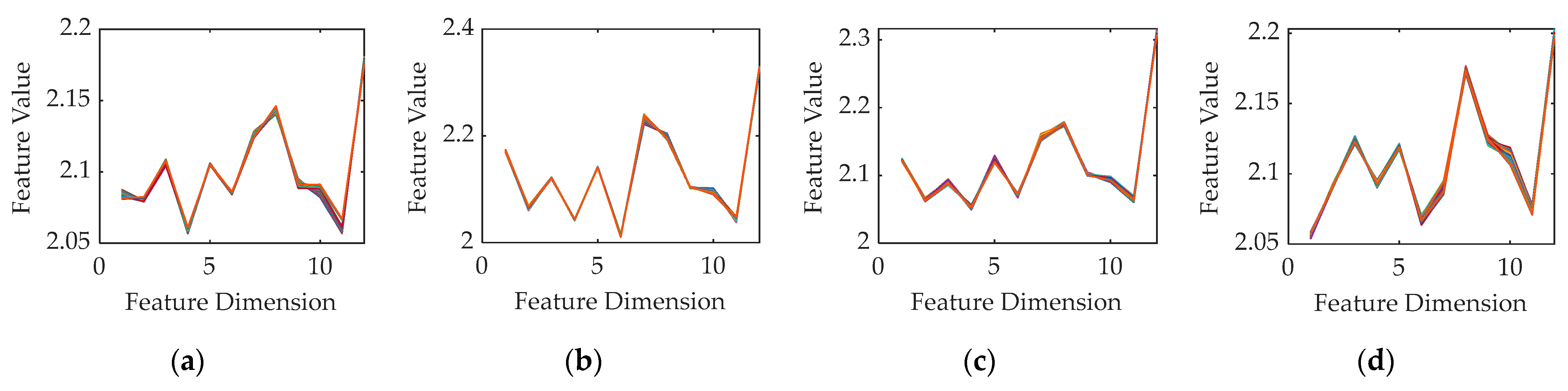
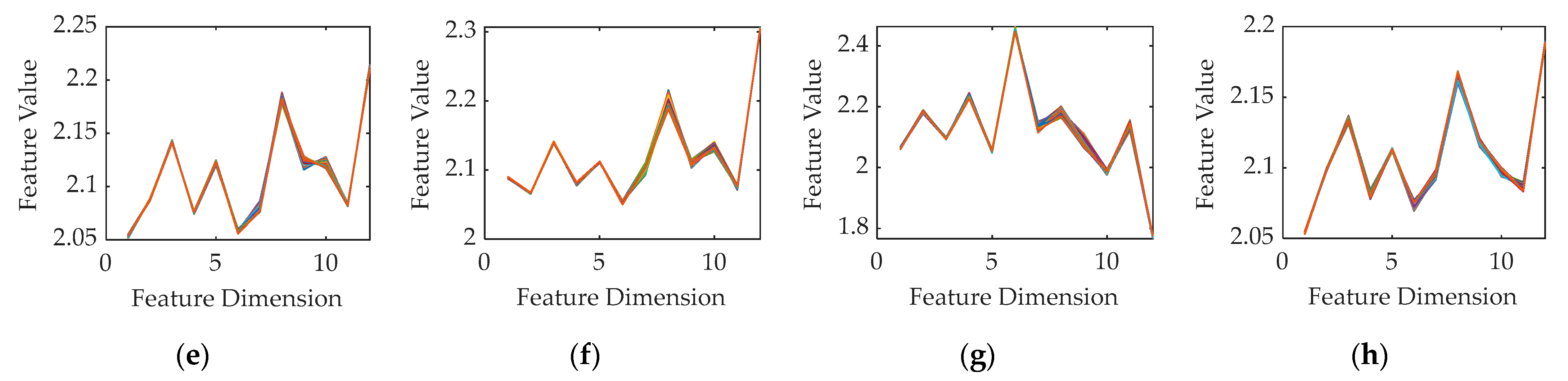
Firstly, the collected data in LOS moving state are taken as an example, and the RFF characteristic vectors of eight ESP8266 modules are drawn in Figure 4. Each module is selected 100 frames of signals, and the feature vectors extracted from each frame of each module are superimposed and drawn on the same figure. As can be seen from the figure, the amplitudes in different dimensions of the eigenvector of different modules are different, and the waveform trend and concave-convex characteristics also have obvious differences, indicating that the module RFF characteristics of the same model also have a certain degree of differentiation. On the other hand, the waveform trends of features extracted from the multiple frames of the same module in the mobile multipath environment are basically the same. After superimposing the characteristic curves of a plethora of signal frames on the same figure, it can be approximatively regarded as falling on the same curve, which indicates that the fingerprint characteristics of the same module are still relatively stable and consistent in the mobile environment and are less affected by the channel.
Next, the extracted RFF feature vectors are trained and tested, and the identification accuracy is used for quantitative comparison and analysis. The 500 PPDU frames per module collected in position p1 are used as the training set, and the 500 frames collected in position p2 to p4 in the static state, 500 frames collected in indoor LOS moving state, and 1000 frames collected in partition NLOS moving state per module are used as the test set. Only the feature vectors of the signals in a fixed position are used for training, and the features of the signals acquired in the remaining fixed positions and moving scenes are used for testing, which can verify that the fingerprint features are independent of position and moving state. The selection of the training set and test set samples above also corresponds to the practical application scenarios. Generally speaking, signal acquisition and training in a static position is achievable, but the moving situation of the V2X devices in the actual working state is variable, which results that the channel and environment during identification are different from those during training. The identification accuracy rates of the three scenes using the random forest and sequential detection methods proposed in this paper are shown in the following Table 1. The accuracy rates in the static state and LOS moving state are both 100%, with a slight drop in the NLOS moving state but still exceeding 99%, which demonstrates that the RFF feature vectors extracted by this method in different positions and different experimental scenes still have a high degree of similarity and are less influenced by the mobility environment.
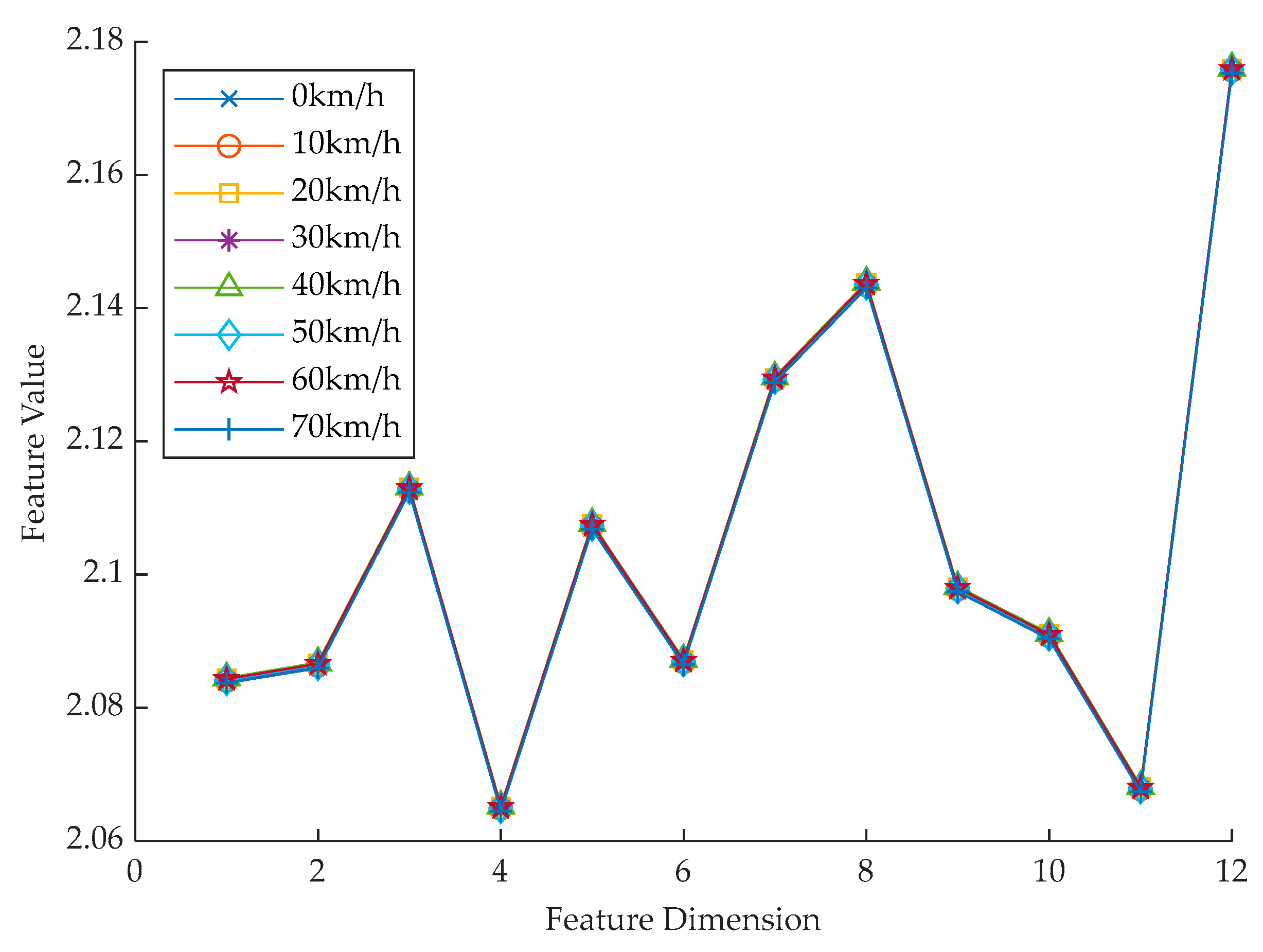
Then, the simulated channel is added through MATLAB to emulate a high-speed moving scene and test the recognition performance in high mobility environment. The frames captured in the static state pass through the Rayleigh channel model, and the mobile Doppler frequency shift is added. The relative moving speed between the module and the USRP is set in the range of 0–70 km/h, increasing every 10 km/h, so that the signal after going through the mobile channel with different speeds can be obtained from the output. Figure 5 below shows the RFF characteristic vectors waveforms of one frame signal of ESP8266 module No. 1 passing through the mobile environment at different speeds from 0 to 70 km/h which reveals that the extracted characteristic value curves of the same frame of signal after experiencing different mobile speeds are basically coincident and are hardly affected by the high-speed movement. Subsequently, the collected and simulated data are used to train and test to calculate the recognition rate. The training set utilizes 500 frames of received signals acquired from each module in the static position p1, while the test set utilizes the 500 frames of signals acquired in the static position p1 to p4 per module which have passed through the simulated channel after they are collected. There is no overlap between the training set samples and the initial samples of the test set that has not experienced the channel. From the test results in Table 2 below, it can be seen that the identification accuracy rate can reach 100% when the relative moving speed is below 20 km/h, and it starts to decrease slightly after the speed exceeds 30 km/h, but the accuracy rate is always above 99% when the speed is between 30–70 km/h. Thus, it can be seen that in the simulated high mobility scenario, the proposed identification mechanism based on RFF still shows strong anti-moving and anti-multipath performance and the recognition rate for eight modules of the same model can still achieve more than 99% when the vehicle speed reaches 70 km/h.
In general, according to the experiments under static and low-speed moving scenes and high-speed simulation tests, the RFF extraction method based on the preamble field features proposed in this paper can extract device fingerprint characteristics with high discrimination and stability for distinguishing and authenticating different devices in a mobile multipath environment at vehicle speed level. Furthermore, the previous research on RFF identification have not focused on the mobile multipath factor in the V2X environment and lack experiments in the case of a high-speed moving state. Thus, the research done in this paper takes special account of the relative movement scene, in which the communication modules are placed in the motion of random path for data collection, and high mobility simulation tests are carried out to make the experimental results more persuasive. The identification accuracy rates of the eight modules in the LOS and NLOS moving state experiments and high-speed simulation tests all exceed 99%, indicating that the method proposed in this paper has the ability to extract the inherent physical characteristics of V2X devices based on DSRC technologies and realize identity recognition.
6. Conclusions
In this paper, a novel identification scheme based on radio frequency fingerprints is presented for DSRC intelligent vehicle networking devices adopting IEEE 802.11p protocol, in which the preamble field features of PPDU frames sent by the DSRC devices are extracted as device fingerprints, and the random forest algorithm and sequential detection method are used to realize the distinction and authentication of different devices. Compared with the existing V2X authentication technologies, the physical layer security technology based on RFF authentication utilizes the unique hardware characteristics of the devices, which can improve the performance against identity forgery without adding extra computation overhead.
The identification method proposed in this article focuses on the impact of mobile multipath channels on RFFs. In the LOS and NLOS mobile experiment scenes and the simulated high-speed scenario up to 70 km/h, the recognition rate of eight DSRC modules of the same model can reach more than 99%. Thus, it can be seen that the RFF features extracted by this method can maintain good stability and location invariance with less influence by mobile channel, and this method has a high practical value in the field of authentication and identification of V2X devices. In future research, the number and model of devices to be identified can be further increased, and the experiment can be conducted in a more complex and changeable environment.
Author Contributions
Conceptualization, T.C., A.H. and Y.J.; Data Curation, T.C.; Formal Analysis, T.C., A.H. and Y.J.; Funding Acquisition, A.H. and Y.J.; Investigation, T.C.; Methodology, T.C., A.H. and Y.J.; Project Administration, A.H. and Y.J.; Resources, A.H. and Y.J.; Software, T.C.; Supervision, A.H. and Y.J.; Validation, T.C.; Visualization, T.C.; Writing—Original Draft, T.C.; Writing—Review and Editing, T.C. and A.H. All authors have read and agreed to the published version of the manuscript.
Funding
This research was funded in part by Jiangsu Provincial Key Laboratory of Network and Information Security No. BM2003201, Jiangsu Key R & D Plan No. BE2019109, the National Natural Science Foundation of China under Grant 61601114, 61602113, 61801115, 61941115, 62001106, Natural Science Foundation of Jiangsu Province under Grant BK20160692, BK20200350, BK20200352, and the Purple Mountain Laboratories for Network and Communication Security.
Institutional Review Board Statement
Not applicable.
Informed Consent Statement
Not applicable.
Data Availability Statement
Not applicable.
Conflicts of Interest
The authors declare no conflict of interest.
References
- Huang, X.; Zhao, D.; Peng, H. Empirical Study of DSRC Performance Based on Safety Pilot Model Deployment Data. IEEE Trans. Intell. Transp. Syst. 2017, 18, 2619–2628. [Google Scholar] [CrossRef] [Green Version]
- Zhao, Z.; Zhang, S.; Lu, Q.; Du, Z.; Ding, Y.; Shen, X. C-V2X Communication Standards: From LTE-V2X to NR-V2X; Posts & Telecom Press: Beijing, China, 2021; pp. 2–7. [Google Scholar]
- Anwar, W.; Franchi, N.; Fettweis, G. Physical Layer Evaluation of V2X Communications Technologies: 5G NR-V2X, LTE-V2X, IEEE 802. 11bd, and IEEE 802.11p. In Proceedings of the 2019 IEEE 90th Vehicular Technology Conference (VTC2019-Fall), Honolulu, HI, USA, 22–25 September 2019; pp. 1–7. [Google Scholar] [CrossRef]
- Hameed Mir, Z.; Filali, F. LTE and IEEE 802.11p for Vehicular Networking: A Performance Evaluation. EURASIP J. Wirel. Commun. Netw. 2014, 2014, 89. [Google Scholar] [CrossRef] [Green Version]
- China Academy of Information and Communications Technology. White Paper on Vehicle Networking; China Academy of Information and Communications Technology: Beijing, China, 2018. [Google Scholar]
- Hu, A.; Li, G. Physical Layer Security in Wireless Communication: Survey. J. Data Acquis. Process. 2014, 29, 341–350. [Google Scholar] [CrossRef]
- Kebande, V.R.; Awaysheh, F.M.; Ikuesan, R.A.; Alawadi, S.A.; Alshehri, M.D. A Blockchain-Based Multi-Factor Authentication Model for Cloud-Enabled Internet of Vehicles. Sensors 2021, 21, 6018. [Google Scholar] [CrossRef] [PubMed]
- Sadiq, A.; Javaid, N.; Samuel, O.; Khalid, A.; Haider, N.; Imran, M. Efficient Data Trading and Storage in Internet of Vehicles using Consortium Blockchain. In Proceedings of the 2020 International Wireless Communications and Mobile Computing (IWCMC), Limassol, Cyprus, 15–19 June 2020; pp. 2143–2148. [Google Scholar] [CrossRef]
- Gao, P.; Yang, R.; Gao, X. Research on “Cloud-Edge-End” Security Protection System of Internet of Things Based on National Secret Algorithm. In Proceedings of the 2019 IEEE 4th Advanced Information Technology, Electronic and Automation Control Conference (IAEAC), Chengdu, China, 20–22 December 2019; pp. 1690–1693. [Google Scholar] [CrossRef]
- Wang, C.; Luo, W.; Mo, X.; Yang, W. Survey on Mutual Trust Authentication and Secure Communication of Internet of Vehicles. Comput. Sci. 2020, 47, 1–9. [Google Scholar] [CrossRef]
- Zhu, W.; Lin, J. Generating Correlated Digital Certificates: Framework and Applications. IEEE Trans. Inf. Forensics Secur. 2016, 11, 1117–1127. [Google Scholar] [CrossRef]
- Agudo, I.; Montenegro-Gómez, M.; Lopez, J. A Blockchain Approach for Decentralized V2X (D-V2X). IEEE Trans. Veh. Technol. 2021, 70, 4001–4010. [Google Scholar] [CrossRef]
- Zeng, K.; Govindan, K.; Mohapatra, P. Non-cryptographic Authentication and Identification in Wireless Networks. IEEE Wirel. Commun. 2010, 17, 56–62. [Google Scholar] [CrossRef]
- Wang, N.; Wang, P.; Alipour-Fanid, A.; Jiao, L.; Zeng, K. Physical Layer Security of 5G Wireless Networks for IoT: Challenges and Opportunities. IEEE Internet Things J. 2019, 6, 8169–8181. [Google Scholar] [CrossRef]
- Yuan, H.L. Research on the Key Technologies of Wireless Network Physical Layer Authentication Based on RF Fingerprint. Ph.D. Dissertation, Southeast University, Nanjing, China, 2011. [Google Scholar]
- Li, G.; Yu, J.; Hu, A. Research on Physical-layer Security Based on Device and Channel Characteristics. J. Cryptologic Res. 2020, 7, 224–248. [Google Scholar] [CrossRef]
- Zeng, Y.; Chen, X.; Lin, Y.; Hao, X.; Xu, X.; Wang, L. Review of Radio Frequency Fingerprint Identification. Chin. J. Radio Sci. 2020, 35, 305–315. [Google Scholar] [CrossRef]
- Ali, A.; Uzundurukan, E.; Kara, A. Improvements on Transient Signal Detection for RF Fingerprinting. In Proceedings of the 2017 25th Signal Processing and Communications Applications Conference (SIU), Antalya, Turkey, 15–18 May 2017; pp. 1–4. [Google Scholar] [CrossRef]
- Kennedy, I.; Scanlon, P.; Buddhikot, M. Passive Steady State RF Fingerprinting: A Cognitive Technique for Scalable Deployment of Co-Channel Femto Cell Underlays. In Proceedings of the 2008 3rd IEEE Symposium on New Frontiers in Dynamic Spectrum Access Networks, Chicago, IL, USA, 14–17 October 2008; pp. 1–12. [Google Scholar] [CrossRef]
- Wheeler, C.G.; Reising, D.R. Assessment of the Impact of CFO on RF-DNA Fingerprint Classification Performance. In Proceedings of the 2017 International Conference on Computing, Networking and Communications (ICNC), Silicon Valley, CA, USA, 26–29 January 2017; pp. 110–114. [Google Scholar] [CrossRef]
- Williams, M.; Munns, S.; Temple, M.; Mendenhall, M. RF-DNA Fingerprinting for Airport WiMax Communications Security. In Proceedings of the 2010 Fourth International Conference on Network and System Security, Melbourne, VIC, Australia, 1–3 September 2010; pp. 32–39. [Google Scholar] [CrossRef]
- Peng, L.; Hu, A.; Zhang, J.; Jiang, Y.; Yu, J.; Yan, Y. Design of a Hybrid RF Fingerprint Extraction and Device Classification Scheme. IEEE Internet Things J. 2019, 6, 349–360. [Google Scholar] [CrossRef]
- Chatterjee, B.; Das, D.; Maity, S.; Sen, S. RF-PUF: Enhancing IoT Security through Authentication of Wireless Nodes Using In-Situ Machine Learning. IEEE Internet Things J. 2019, 6, 388–398. [Google Scholar] [CrossRef] [Green Version]
- Zhou, X.; Hu, A.; Li, G.; Peng, L.; Xing, Y.; Yu, J. Design of a Robust RF Fingerprint Generation and Classification Scheme for Practical Device Identification. In Proceedings of the 2019 IEEE Conference on Communications and Network Security (CNS), Washington, DC, USA, 10–12 June 2019; pp. 196–204. [Google Scholar] [CrossRef]
- Xing, Y.; Hu, A.; Zhang, J.; Yu, J.; Li, G.; Wang, T. Design of a Robust Radio-Frequency Fingerprint Identification Scheme for Multimode LFM Radar. IEEE Internet Things J. 2020, 7, 10581–10593. [Google Scholar] [CrossRef]
- Wang, S.; Peng, L.; Fu, H.; Hu, A.; Zhou, X. A Convolutional Neural Network-Based RF Fingerprinting Identification Scheme for Mobile Phones. In Proceedings of the IEEE INFOCOM 2020—IEEE Conference on Computer Communications Workshops (INFOCOM WKSHPS), Toronto, ON, Canada, 6–9 July 2020; pp. 115–120. [Google Scholar] [CrossRef]
- IEEE Standard 802.11p-2010; IEEE Standard for Information Technology—Local and Metropolitan Area Networks—Specific Requirements—Part 11: Wireless LAN Medium Access Control (MAC) and Physical Layer (PHY) Specifications Amendment 6: Wireless Access in Vehicular Environments. IEEE: New York, NY, USA, 2010; 11p. [CrossRef]
- Fernandez, J.A.; Borries, K.; Cheng, L.; Vijaya Kumar, B.V.K.; Stancil, D.D.; Bai, F. Performance of the 802.11p Physical Layer in Vehicle-to-Vehicle Environments. IEEE Trans. Veh. Technol. 2012, 61, 3–14. [Google Scholar] [CrossRef]
- IEEE Standard 802.11-2016; IEEE Standard for Information Technology—Telecommunications and Information Exchange Between Systems—Local and Metropolitan Area Networks—Specific Requirements—Part 11: Wireless LAN Medium Access Control (MAC) and Physical Layer (PHY) Specifications. IEEE: New York, NY, USA, 2016. [CrossRef]
- Yu, J.; Li, G.; Hu, A. Time-domain Baseband Modeling of Radio Frequency Fingerprint for Zero-IF Digital Communication Transmitter. J. Terahertz Sci. Electron. Inf. Technol. 2021, 19, 603–616, 622. [Google Scholar] [CrossRef]
- Zhou, Z. Machine Learning; Tsinghua University Press: Beijing, China, 2016; pp. 178–181. [Google Scholar]
Figure 1.
Flow chart of DSRC radio frequency fingerprint extraction and identification.

Figure 2.
IEEE 802.11p OFDM PPDU frame format.

Figure 3.
Schematic diagram of laboratory.

Figure 4.
Multiple frames superimposed RFF features of eight ESP8266 modules in indoor LOS moving state: (a) No. 1; (b) No. 2; (c) No. 3; (d) No. 4; (e) No. 5; (f) No. 6; (g) No. 7; (h) No. 8.
Figure 4.
Multiple frames superimposed RFF features of eight ESP8266 modules in indoor LOS moving state: (a) No. 1; (b) No. 2; (c) No. 3; (d) No. 4; (e) No. 5; (f) No. 6; (g) No. 7; (h) No. 8.


Figure 5.
RFF features of one frame signal of ESP8266 module No. 1 in simulated high mobility environment.
Figure 5.
RFF features of one frame signal of ESP8266 module No. 1 in simulated high mobility environment.


Table 1.
Identification accuracy rate (%) of eight ESP8266 modules based on RFF features in static and moving states.
Table 1.
Identification accuracy rate (%) of eight ESP8266 modules based on RFF features in static and moving states.
| Module Number | Experimental Scene | ||
|---|---|---|---|
| Static State | LOS Moving State | NLOS Moving State | |
| 1 | 100 | 100 | 99.60 |
| 2 | 100 | 100 | 100 |
| 3 | 100 | 100 | 100 |
| 4 | 100 | 100 | 100 |
| 5 | 100 | 100 | 99.50 |
| 6 | 100 | 100 | 98.70 |
| 7 | 100 | 100 | 100 |
| 8 | 100 | 100 | 100 |
| Overall Average | 100 | 100 | 99.73 |
Table 2.
Identification accuracy rate (%) of eight ESP8266 modules based on RFF features in simulated high mobility environment.
Table 2.
Identification accuracy rate (%) of eight ESP8266 modules based on RFF features in simulated high mobility environment.
| Module Number | Speeds (km/h) | |||||||
|---|---|---|---|---|---|---|---|---|
| 0 | 10 | 20 | 30 | 40 | 50 | 60 | 70 | |
| 1 | 100 | 100 | 100 | 100 | 100 | 100 | 100 | 99.90 |
| 2 | 100 | 100 | 100 | 100 | 100 | 100 | 100 | 100 |
| 3 | 100 | 100 | 100 | 100 | 100 | 100 | 100 | 100 |
| 4 | 100 | 100 | 100 | 99.50 | 100 | 100 | 99.90 | 96.70 |
| 5 | 100 | 100 | 100 | 100 | 100 | 100 | 100 | 100 |
| 6 | 100 | 100 | 100 | 100 | 100 | 100 | 100 | 100 |
| 7 | 100 | 100 | 100 | 100 | 100 | 100 | 100 | 100 |
| 8 | 100 | 100 | 100 | 99.25 | 100 | 94.95 | 97.55 | 99.45 |
| Overall Average | 100 | 100 | 100 | 99.84 | 100 | 99.37 | 99.68 | 99.51 |
Publisher’s Note: MDPI stays neutral with regard to jurisdictional claims in published maps and institutional affiliations. |
© 2022 by the authors. Licensee MDPI, Basel, Switzerland. This article is an open access article distributed under the terms and conditions of the Creative Commons Attribution (CC BY) license (https://creativecommons.org/licenses/by/4.0/).
Share and Cite
MDPI and ACS Style
Chen, T.; Hu, A.; Jiang, Y. Radio Frequency Fingerprint-Based DSRC Intelligent Vehicle Networking Identification Mechanism in High Mobility Environment. Sustainability 2022, 14, 5037. https://0-doi-org.brum.beds.ac.uk/10.3390/su14095037
AMA Style
Chen T, Hu A, Jiang Y. Radio Frequency Fingerprint-Based DSRC Intelligent Vehicle Networking Identification Mechanism in High Mobility Environment. Sustainability. 2022; 14(9):5037. https://0-doi-org.brum.beds.ac.uk/10.3390/su14095037
Chicago/Turabian StyleChen, Tianshu, Aiqun Hu, and Yu Jiang. 2022. "Radio Frequency Fingerprint-Based DSRC Intelligent Vehicle Networking Identification Mechanism in High Mobility Environment" Sustainability 14, no. 9: 5037. https://0-doi-org.brum.beds.ac.uk/10.3390/su14095037
Note that from the first issue of 2016, this journal uses article numbers instead of page numbers. See further details here.