Article

Load Frequency Control and Automatic Voltage Regulation in a Multi-Area Interconnected Power System Using Nature-Inspired Computation-Based Control Methodology

1
Department of Electrical Engineering, FET, International Islamic University, Islamabad 44000, Pakistan
2
Department of ICT and Natural Sciences, Norwegian University of Science and Technology, Larsgårdsve-gen, 2, 6009 Ålesund, Norway
3
School of Information Science and Engineering, Ningbotech University, Ningbo 315100, China
4
Department of Computer Engineering, Taif University, Taif 21944, Saudi Arabia
5
College of Computer and Information Sciences, Prince Sultan University, Riyadh 11586, Saudi Arabia
6
Automated Systems and Soft Computing Lab (ASSCL), Prince Sultan University, Riyadh 12435, Saudi Arabia
7
Faculty of Computers and Artificial Intelligence, Benha University, Benha 13518, Egypt
*
Authors to whom correspondence should be addressed.
Sustainability 2022, 14(19), 12162; https://0-doi-org.brum.beds.ac.uk/10.3390/su141912162
Submission received: 19 August 2022 / Revised: 10 September 2022 / Accepted: 20 September 2022 / Published: 26 September 2022
(This article belongs to the Special Issue Smart Grid Analytics for Sustainability and Urbanization in Big Data)

Abstract

:
The stability control of nominal frequency and terminal voltage in an interconnected power system (IPS) is always a challenging task for researchers. The load variation or any disturbance affects the active and reactive power demands, which badly influence the normal working of IPS. In order to maintain frequency and terminal voltage at rated values, controllers are installed at generating stations to keep these parameters within the prescribed limits by varying the active and reactive power demands. This is accomplished by load frequency control (LFC) and automatic voltage regulator (AVR) loops, which are coupled to each other. Due to the complexity of the combined AVR-LFC model, the simultaneous control of frequency and terminal voltage in an IPS requires an intelligent control strategy. The performance of IPS solely depends upon the working of the controllers. This work presents the exploration of control methodology based on a proportional integral–proportional derivative (PI-PD) controller with combined LFC-AVR in a multi-area IPS. The PI-PD controller was tuned with recently developed nature-inspired computation algorithms including the Archimedes optimization algorithm (AOA), learner performance-based behavior optimization (LPBO), and modified particle swarm optimization (MPSO). In the earlier part of this work, the proposed methodology was applied to a two-area IPS, and the output responses of LPBO-PI-PD, AOA-PI-PD, and MPSO-PI-PD control schemes were compared with an existing nonlinear threshold-accepting algorithm-based PID (NLTA-PID) controller. After achieving satisfactory results in the two-area IPS, the proposed scheme was examined in a three-area IPS with combined AVR and LFC. Finally, the reliability and efficacy of the proposed methodology was investigated on a three-area IPS with LFC-AVR with variations in the system parameters over a range of  ± 50%. The simulation results and a comprehensive comparison between the controllers clearly demonstrates that the proposed control schemes including LPBO-PI-PD, AOA-PI-PD, and MPSO-PI-PD are very reliable, and they can effectively stabilize the frequency and terminal voltage in a multi-area IPS with combined LFC and AVR.

1. Introduction

Research efforts and specializations in power systems are increasing day by day to acquire reliable power with nominal voltage and frequency. In a power system, the main goal is to provide nominal voltage and frequency to all consumers without any interruption. The simultaneous control of load frequency and terminal voltage in an interconnected electrical power system is the fundamental area of research for all practicing engineers. The mutilation of frequency or voltage can spoil the performance and life expectancy of equipment associated with IPS [1]. The active and reactive powers can change with load demands in IPS. The active power can be adjusted by a speed governor in an LFC loop, whereas reactive power can be controlled by an exciter in an AVR loop. In order to fulfill the active power demand, a turbine input is continuously regulated in LFC, or else the changing frequency will vary the machine’s speed. In AVR, terminal voltage remains within the prescribed limit if the excitation of generators is regulated properly to match the reactive power demand. A lot of literature is available on individual AVR or LFC systems; however, relatively less research work has been carried out on combined LFC-AVR due to its complex design. The PID controller was extensively used in multi-area IPS due to its simple design and easier installation. For instance, the artificial electric field algorithm-based hybridized approach to tune the fuzzy PID controller was suggested for combined LFC and AVR with the incorporation of different energy storage devices [1]. A particle swarm-optimized Ziegler–Nicholas (PSO-ZN)-based PID controller was examined for AVR-LFC control in PV integration and a conventional power system [2]. PI and PID with filter (PIDF) controllers based on the sine cosine algorithm were also inquired for a two-area, two-source IPS. The redox flow batteries were assimilated for further improvements in the system dynamics [3]. The doctor and patient optimization (DPO)-based accelerating PID controller (PIDA) was proposed for the LFC-AVR problem in a multi-area IPS with renewable energy sources [4]. The PID controller was employed for collective AVR-LFC in a two-area IPS. A nonlinear threshold-accepting algorithm was explored to find the optimum parameters of the PID controller [5]. PI and I controllers for AVR and an LFC loop were also investigated for a single-area IPS [6]. In [7], due to the inclusion of deregulated environments in IPS, a fuzzy logic controller (FLC) was recommended for a two-area LFC-AVR problem. A fractional order controller (PIDµF) based on the lightning search algorithm (LSA) was also proposed for LFC-AVR with wind and a reheat thermal plant as the generating companies (GENCOs) of area-1,and with diesel and a nonlinear reheat thermal plant as the GENCOs of area-2 under deregulated environments [8].The PID controller was optimized with the hybridization of the artificial electric field algorithm and differential evolution for a two-area IPS with a joint LFC-AVR [9,10]. In [11], PID with the firefly algorithm was employed for a two-area IPS with AVR-LFC. The moth flame optimization (MFO)-based fractional order PID controller was proposed for both LFC and AVR loops [12]. For a single-area synchronous generator, the combined LFC-AVR was explored using a hardware environment [13]. In [14,15], the authors inspected the firefly algorithm, particle swarm optimization, and the genetic algorithm-based PID controller for AVR-LFC loops. The novel state-observer (SO)-based integral double-derivative controller based on magneto-tactic-bacteria optimization (MBO) was presented for voltage–frequency control in a hybrid IPS [16]. The model predictive controller (MPC) was also used to improve AVR-LFC responses [17]. In [18], the heuristic computation-based two degrees of freedom state-feedback PI controller was exploited for the AVR loop in synchronous generators. A combination of the bacterial foraging optimization algorithm and particle swarm optimization was utilized to tune the PI controller for the AVR system with a static synchronous compensator [19]. In [20], a sliding mode controller with the addition of a gene ralized extended state observer was successfully explored to optimize the LFC loop in a multi-area IPS. The PID controller tuned with the many optimizing liaisons (MOL) algorithm was applied to a two-area IPS with non-reheat thermal sources in the presence of GDB [21]. Moreover, a comprehensive research work was presented for individual LFC loops as presented in [22,23,24,25,26,27,28,29,30,31,32,33,34,35,36,37]. A brief literature summary of AVR-LFC is provided in Table 1. It can be seen that much less attention has been given to the combined LFC-AVR problem in multi-area IPS due to its complex structure. The literature survey also depicts that modified forms of the PID controller were explored very rarely for combined AVR-LFC. Different modified forms such as PI, PIDF, PIDµF, and FO-IDF have been explored due to their excellent time response characteristics with fast convergence, but the PI-PD controller has not been employed for combined LFC-AVR multi-area IPS. Due to its modified structure having a control branch in the feedback path, complex systems can be well optimized with PI-PD as compared to classical control schemes such PI and PID, etc. To obtain optimal controller parameters, an intelligent tuning algorithm is needed, which can optimize the controller with minimum error/fitness. In the past, nature-inspired optimization algorithms have received a lot of attention from researchers because of their strengths and abilities to tackle a variety of complex optimization issues in engineering. These strategies have also been used successfully to obtain optimal controller parameters. The classical nature-inspired computing techniques have shown very satisfactory performances for both individual and combined LFC-AVR. Moreover, researchers have also presented some novel nature-computing algorithms such as dandelion optimizer [38], modified particle swarm optimization (MPSO), bald eagle search (BES) [39], the transient search algorithm (TSO) [40], learner performance-based behavior optimization (LPBO) [41], the Archimedes optimization algorithm (AOA) [42], etc. These recently introduced techniques such as MPSO, LPBO, and AOA have not been considered for the optimal tuning of the PI-PD control scheme. It will be worth choosing these nature-inspired techniques for the optimization of multi-area IPS with combined LFC-AVR. Keeping in mind the existing research gap, the nature-inspired computation-based PI-PD control scheme is proposed in this research for multi-area IPS with combined AVR-LFC. The main contributions of this work are:
  • The modeling of combined AVR-LFC for two-area and three-area IPS;
  • The modeling of the PI-PD control scheme and its optimization using the Archimedes optimization algorithm (AOA), learner performance-based behavior optimization (LPBO), and modified particle swarm optimization (MPSO);
  • The formulation of fitness functions for the optimization of proposed controller;
  • Further, a comprehensive performance comparison is carried out between LPBO-PI-PD, AOA-PI-PD, and MPSO-PI-PD in two-area IPS. Moreover, the efficacy of the proposed control schemes has been tested in a three-area IPS with a combined LFC-AVR problem;
  • The reliability of the proposed control methodology has been illustrated by altering the system parameters of three-area IPS over a range of  ± 50%.
Table 2 demonstrates the nomenclature used in this study. This research paper is organized in following way: The power system model is described in Section 2. The proposed control methodology is presented in Section 3. Section 4 contains a description and flow charts of nature-inspired computation algorithms including LPBO, AOA, and MPSO. The implementation and results of the proposed techniques are summarized in Section 5. Lastly, conclusions and future guidelines are given in Section 6.

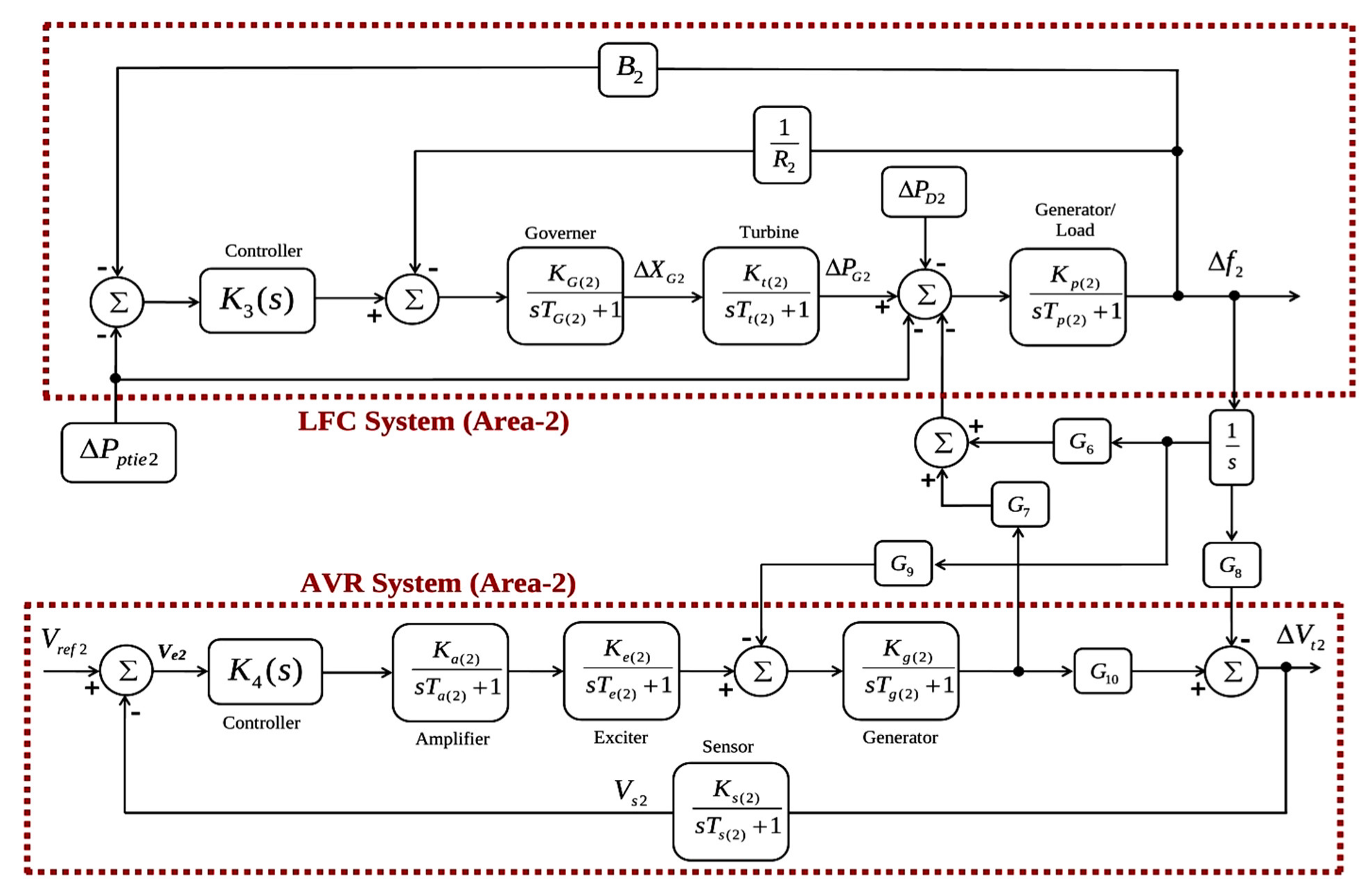
2. Power System Model

The multi-area IPS model under study is shown in Figure 1. The terminal voltage was maintained at nominal value by stabilizing the generator fields, while the load frequency was regulated by controlling real power. Figure 1a represents the AVR-LFC model of a power system for a single area, where i and j represent area-1 and area-2, respectively [5].
V t ( i ) , V e ( i ) , V r e f ( i ) , and V s ( i ) refer to the terminal output, error, reference, and sensor voltage in area-1, respectively. The AVR system of area-i consists of a controller ( K 1 ( i ) ( s ) ), amplifier ( K a ( i ) s T a ( i ) + 1 ), generator ( K g ( i ) s T g ( i ) + 1 ), exciter ( K e ( i ) s T e ( i ) + 1 ), and sensor ( K s ( i ) s T s ( i ) + 1 ). Area-1′s LFC system has a controller K 2 ( i ) ( s ) , turbine ( K t ( i ) s T t ( i ) + 1 ), governor ( K G ( i ) s T G ( i ) + 1 ), speed regulation ( R i ), and generator/load ( K p ( i ) s T p ( i ) + 1 ). Δ f ( i ) denotes frequency deviation (Hz), Δ X G ( i ) shows the valve position of the governor (p.u.MW), Δ P G ( i ) represents the deviation in the output of the generator (p.u.MW), Δ P D ( i ) (p.u.MW) denotes the deviation in load, speed regulation is represented by R ( i ) (Hz p.u.MW−1), and Δ P t i e ( i ) is the tie–line power. The purpose of tie–line is to interconnect multiple areas in IPS. Figure 1b shows the tie–line connections. The synchronization coefficient between area-i and area-j is represented by Tij.

3. Proposed Control Methodology

The proportional integral derivative (PID) controller is commonly utilized in industrial applications owing to its easier implementation and simpler structure. The PID controller provides a satisfactory performance in most of the systems; however, the modified forms of the PID control structure have shown improved performance in many control systems, such as the AVR-LFC interconnected power system. The proportional integral–proportional derivative controller (PI-PD) is a modified version of PID, which is designed in such a way to eliminate system errors with optimum transient and steady state response [43]. The PI part of PI-PD exists in a feed forward path and directly responds to the error signal coming from the summing junction. The PD part is located in the feedback path, and it is unaffected by sudden changes in the set point specification. The closed-loop response can be improved significantly with the addition of a controller part in the feedback path. The PI-PD controller has been successfully employed in the recent past in different applications [44,45,46,47,48,49,50]. The proposed control methodology with the combined LFC-AVR system is given in Figure 2. The transfer function of PI-PD controllers is represented as:
U ( s ) = ( K p 1 + K i s ) E ( s ) ( K p 2 + K d s ) Y ( s )
E ( s ) = Y ( s ) R ( s )
where U(s), Y(s), R(s), and E(s) denote the control, output, reference, and error signals, respectively. The cost function (J) is minimized to obtain the best possible parameters of the controllers. J depends upon E(s), which is basically the difference between the output and reference signal.
In order to minimize the error signal, different types of performance indices can be used such as the integral of the squared value of the error signal (ISE), the integral of the time multiplied with the absolute value of the error signal (ITAE), the integral of the time multiplied with the squared value of the error signal (ITSE), and the integral of the absolute value of error (IAE) represented by the following equations:
J ISE , two - area = 0 T [ Δ f 1 2 + Δ f 2 2 + Δ V t 1 2 + Δ V t 2 2 + Δ P t i e 12 2 ] d t
J ITAE , two - area   = 0 T t [ | Δ f 1 | + | Δ f 2 | + | Δ V t 1 | + | Δ V t 2 | + | Δ P p t i e 12 | ] d t
J ITSE , two - area = 0 T t [ Δ f 1 2 + Δ f 2 2 + Δ V t 1 2 + Δ V t 2 2 + Δ P t i e 12 2 ] d t
J IAE , two - area = 0 T [ | Δ f 1 | + | Δ f 2 | + | Δ V t 1 | + | Δ V t 2 | + | Δ P p t i e 12 | ] d t
For three-area IPS, we can write:
J ISE , three - area = 0 T [ Δ f 1 2 + Δ f 2 2 + Δ f 3 2 + Δ V t 1 2 + Δ V t 2 2 + Δ V t 3 2 + Δ P t i e 1 2 + Δ P t i e 2 2 + Δ P t i e 3 2 ] d t
J IAE , three - area = 0 T [ | Δ f 1 | + | Δ f 2 | + | Δ f 3 | + | Δ V t 1 | + | Δ V t 2 | + | Δ V t 3 | + | Δ P p t i e 1 | + | Δ P p t i e 2 | + | Δ P p t i e 3 | ] d t
J ITSE , three - area = 0 T t [ Δ f 1 2 + Δ f 2 2 + Δ f 3 2 + Δ V t 1 2 + Δ V t 2 2 + Δ V t 3 2 + Δ P t i e 1 2 + Δ P t i e 2 2 + Δ P t i e 3 2 ] d t
J ITAE , three - area = 0 T t [ | Δ f 1 | + | Δ f 2 | + | Δ f 3 | + | Δ V t 1 | + | Δ V t 2 | + | Δ V t 3 | + | Δ P p t i e 1 | + | Δ P p t i e 2 | + | Δ P p t i e 3 | ] d t
where,
Δ V t 1 = V r e f V t 1 Δ V t 2 = V r e f V t 2 Δ V t 3 = V r e f V t 3
Δ P p t i e 1 = Δ P p t i e 12 + Δ P p t i e 13 Δ P p t i e 2 = Δ P p t i e 21 + Δ P p t i e 23 Δ P p t i e 3 = Δ P p t i e 31 + Δ P p t i e 32
When the cost function is minimized, the algorithm returns the best optimum parameters of the controller. To optimize the cost function (J), nature-inspired computation algorithms including LPBO, AOA, and MPSO were adapted.

4. Nature-Inspired Computation Algorithms

Due to their ability to solve complex valued problems, nature-inspired computation algorithms have gained brilliant attention in IPS. Keeping in view their remarkable contribution, an effort was made in this research to optimize the combined LFC and AVR-based IPS using nature-inspired computation techniques.

4.1. Learner Performance-Based Behavior Optimization

Rashid and Rahman presented a novel nature-inspired learner performance-based behavior optimization (LPBO) technique in 2020. The basic concept behind this algorithm is based on the fact that how students are admitted to different departments of a university is based on their high school performance. After admission, students must be able to improve their intellectual level to improve their skills. In this way, both exploitation and exploration phases are preserved. In this algorithm, a random population is generated with various ranges of grade point average (GPA). The applications of some of these learners will be rejected or accepted based on their fitness. After that, the population is divided in to subpopulation. Fitness is calculated and is then sorted into separate groups. The new population’s structure is changed using crossover and mutation operators. A specified number of learners is acquired by different departments based on the minimum GPA criteria. This rejection and acceptance process is continued until all departments have their vacancies filled. Population fitness is improved in each iteration based on group learning, intellectual level, and teaching level [41]. Figure 3 presents the flow chart of the LPBO algorithm. Note that the LPBO population represents the PI-PD controller’s parameters in this case.

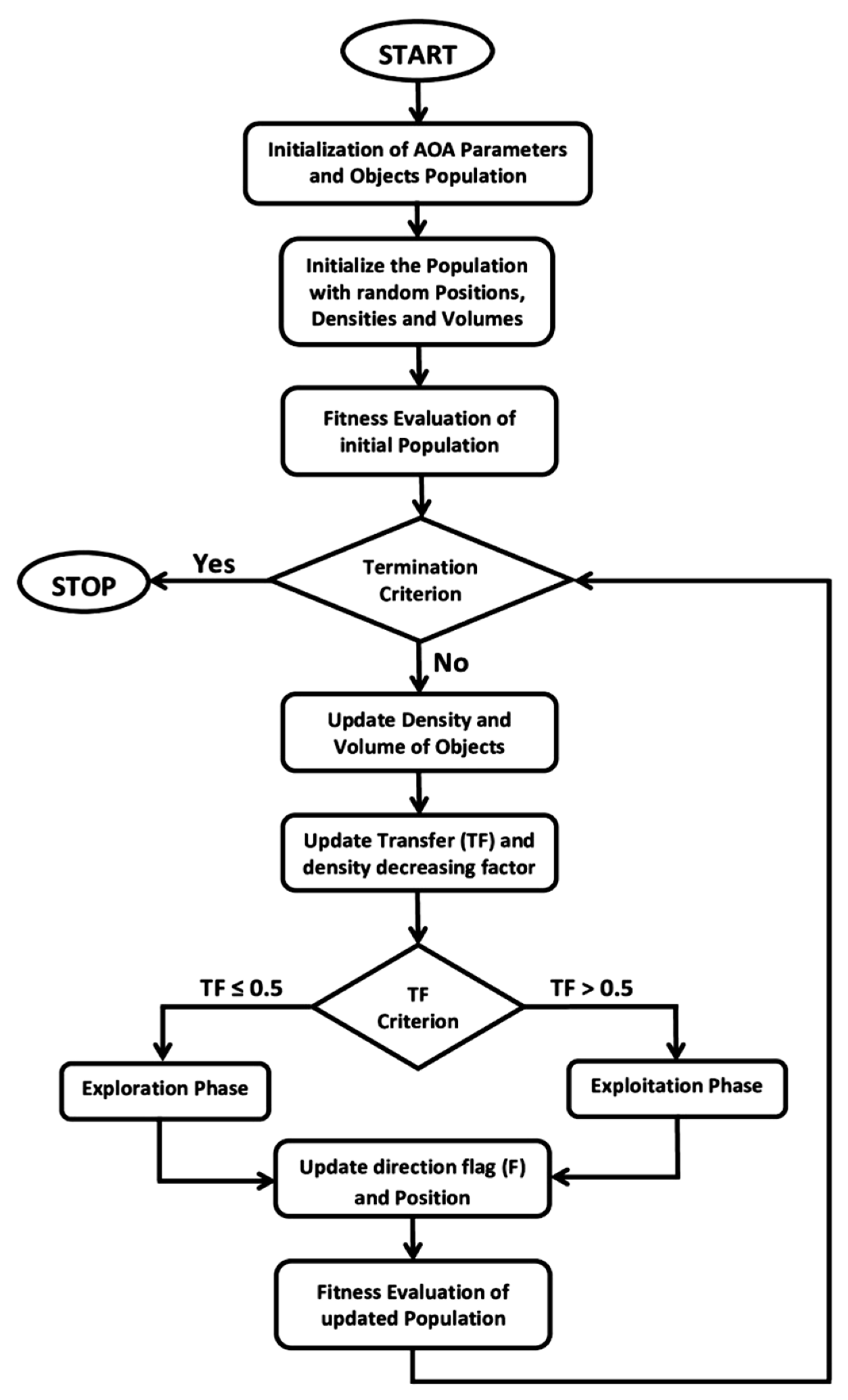
4.2. Archimedes Optimization Algorithm

The Archimedes optimization algorithm (AOA) is a new state-of-the-art algorithm based on the Archimedes principle. It deals with both convex and non-convex problems. It was invented in 2021 by Fatmaand Houssein. It defines the relationship between a buoyant force and an object submerged in water. The object will sink if the displaced fluid weight is less than the weight of the object. Similarly, if the displaced fluid and object weight are equal, the object floats on the fluid. An object has volume, acceleration, and density that results in the buoyancy force, as a result fluid’s net force is always zero. AOA is a very effective nature-inspired algorithm in a way that it analyzes a problem with a global optimum solution. AOA fences in both exploitation and exploration phases since it is a global optimization algorithm. A comprehensive area must be examined to identify the global optimum solution of a given problem. Firstly, the fluid’s random position is initialized, and then AOA evaluates the initial population fitness to discover the best possible solution until the selection criteria are met. The density and volume of each object changes at each AOA iteration. The new density, volume, and acceleration are obtained using the object’s fitness. The AOA population represents the PI-PD controller’s parameters [42]. Figure 4 presents a flow chart diagram of AOA.

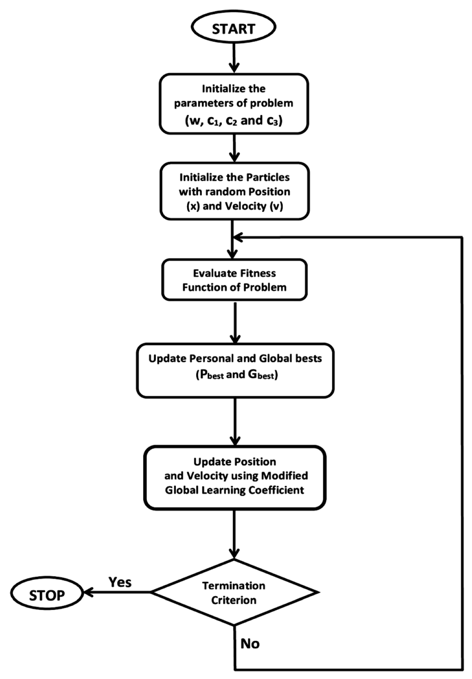
4.3. Modified Particle Swarm Optimization (PSO)

Drawing inspiration from swarm intelligence, Eberhart and Kennedy proposed the particle swarm optimization (PSO) algorithm in 1995. In PSO, the movement of particles (candidate solutions) over a defined search space depends upon their velocity and position. The movement of particles is incited by the best possible positions known as local bests. These local bests lead particles toward the best possible position [51]. In modified particle swarm optimization (MPSO), the global learning coefficient is updated using a combination of existing local and global learning coefficients. The modification in the PSO algorithm is being made to improve the convergence characteristics of the controller. Figure 5 depicts the flow chart of the MPSO algorithm. Remember that in this research work, the particles represent the PI-PD controller’s parameters.

5. Implementation and Results Discussion

Multiple simulations were carried out in MATLAB/Simulink to express the validation of the proposed control methodology. Firstly, a two-area, two-source IPS with combined LFC and AVR was optimized using LPBO, AOA, and MPSO. ITSE was chosen as the error criterion, due to efficient error convergence characteristics. After achieving successful results, the proposed methodology was applied to a three-area, three-source IPS with LFC-AVR loops.

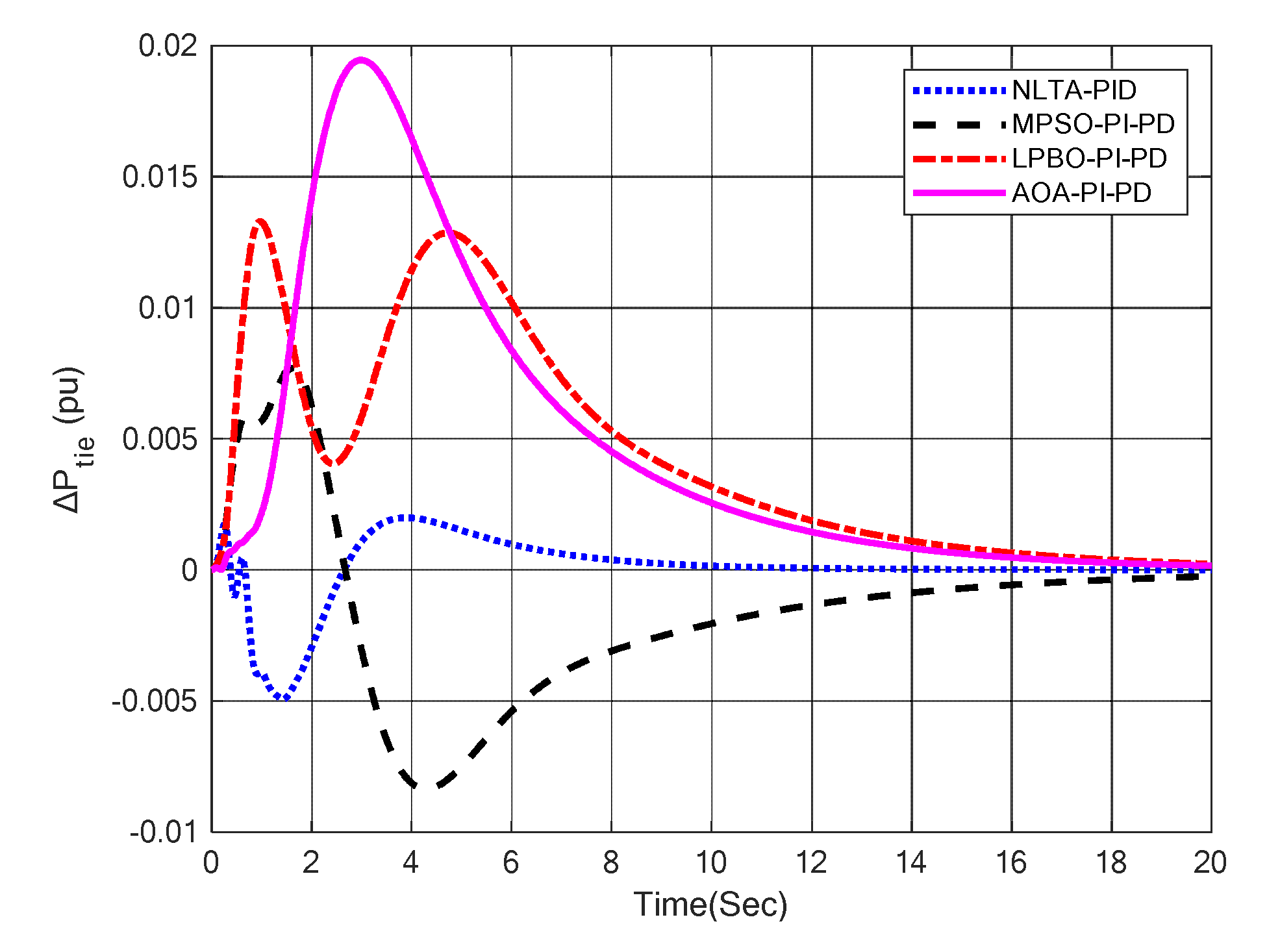
5.1. Optimization of Two-Area Interconnected Power System

The two-area IPS model under investigation with a collective LFC-AVR system is shown in Figure 6. The system parameters of the two-area IPS are specified in Appendix A. The system parameters of area-1 and area-2 were chosen from [5] for a direct comparison of the proposed methodology with the NLTA-PID controller. The parameters of optimization algorithms such as MPSO, LPBO, and AOA used in simulations are given in Table 3. The tie–line connection between area-1 and are-2 can be established using Figure 7. The optimal parameters of MPSO-PI-PD, LPBO-PI-PD, and AOA-PI-PD control schemes are given in Table 4. For the sake of the assessment of the proposed control schemes, the evaluation of the time response of each schemes was carried out and comparisons were made with the results of NLTA-PID [5]. Further, a comparison between the proposed control schemes such as MPSO-PI-PD, LPBO-PI-PD, and AOA-PI-PD is also presented in detail in this section.
Figure 8 shows the frequency deviation curves of area-1 and area-2 using NLTA-PID [5], MPSO-PI-PD, LPBO-PI-PD, and AOA-PI-PD control techniques in a two-area IPS, respectively. It can be seen that the proposed control schemes provided a very satisfactory frequency deviation response. For the area-1 LFC, the settling time of NLTA-PID [5] was lower than the proposed schemes but at the cost of a high undershoot. NLTA-PID provided an undershoot of −0.285, whereas the proposed MPSO-PI-PD, LPBO-PI-PD, and AOA-PI-PD provided−0.130, −0.135, and −0.115, respectively. It can be noticed that the proposed MPSO-PI-PD, LPBO-PI-PD, and AOA-PI-PD provided 54%, 52.6%, and 60%, respectively, better undershoot responses as compared to the NLTA-PID controller in area-1. For area-2, NLTA-PD provided a quick settling, but it provided an undershoot of −0.275, whereas the proposed MPSO-PI-PD, LPBO-PI-PD, and AOA-PI-PD provided−0.135, −0.170, and −0.120, respectively. It was verified that the proposed MPSO-PI-PD, LPBO-PI-PD, and AOA-PI-PD provided 51%, 38%, and 56%, respectively, better undershoot responses as compared to the NLTA-PID controller. The percentages of overshoots and steady state (s-s) errors were almost zero with each proposed technique.
Figure 9 shows the terminal voltage of area-1 and area-2 using the NLTA-PID, MPSO-PI-PD, LPBO-PI-PD, and AOA-PI-PD control techniques in a two-area IPS, respectively. It is clear that the proposed control schemes provided a very satisfactory transient response in both area-1 and area-2. It is identified that NLTA-PID provided 18% and 17% overshoot in area-1 and area-2, respectively, but the proposed technique provided a negligible overshoot percentage at the cost of the settling time with all tuning techniques. It can be observed that the proposed LPBO-PI-PD and AOA-PI-PD control schemes produced settling times approximately the same as those achieved by NLTA-PID.
Figure 10 shows the tie–line power response using NLTA-PID, MPSO-PI-PD, LPBO-PI-PD, and AOA-PI-PD control techniques in a two-area IPS, respectively. It can be observed from the results that LPBO-PI-PD and AOA-PI-PD provided tie–line power responses with no undershoot; however, this was at the cost of a slightly small overshoot. In addition, the tie–line power responses yielded by MPSO-PI-PD, LPBO-PI-PD, and AOA-PI-PD were satisfactory.
Table 5 and Table 6 show the summary of LFC and AVR responses using NLTA-PID, MPSO-PI-PD, LPBO-PI-PD and AOA-PI-PD control schemes in a two-area IPS, respectively.
Figure 11 shows the graphical comparison of the performance parameters of NLTA-PID, MPSO-PI-PD, LPBO-PI-PD, and AOA-PI-PD control techniques in a two-area IPS, respectively. It is very clear that the proposed PI-PD control schemes provided relatively better responses in terms of the undershoot in LFC and overshoot percentage in AVR as compared to the NLTA-PID controller. From Table 5 and Table 6 and Figure 11, it is concluded that the proposed MPSO-PI-PD, LPBO-PI-PD, and AOA-PI-PD were effective for maintaining the frequency and voltage within the prescribed values with a satisfactory performance in a two-area IPS.

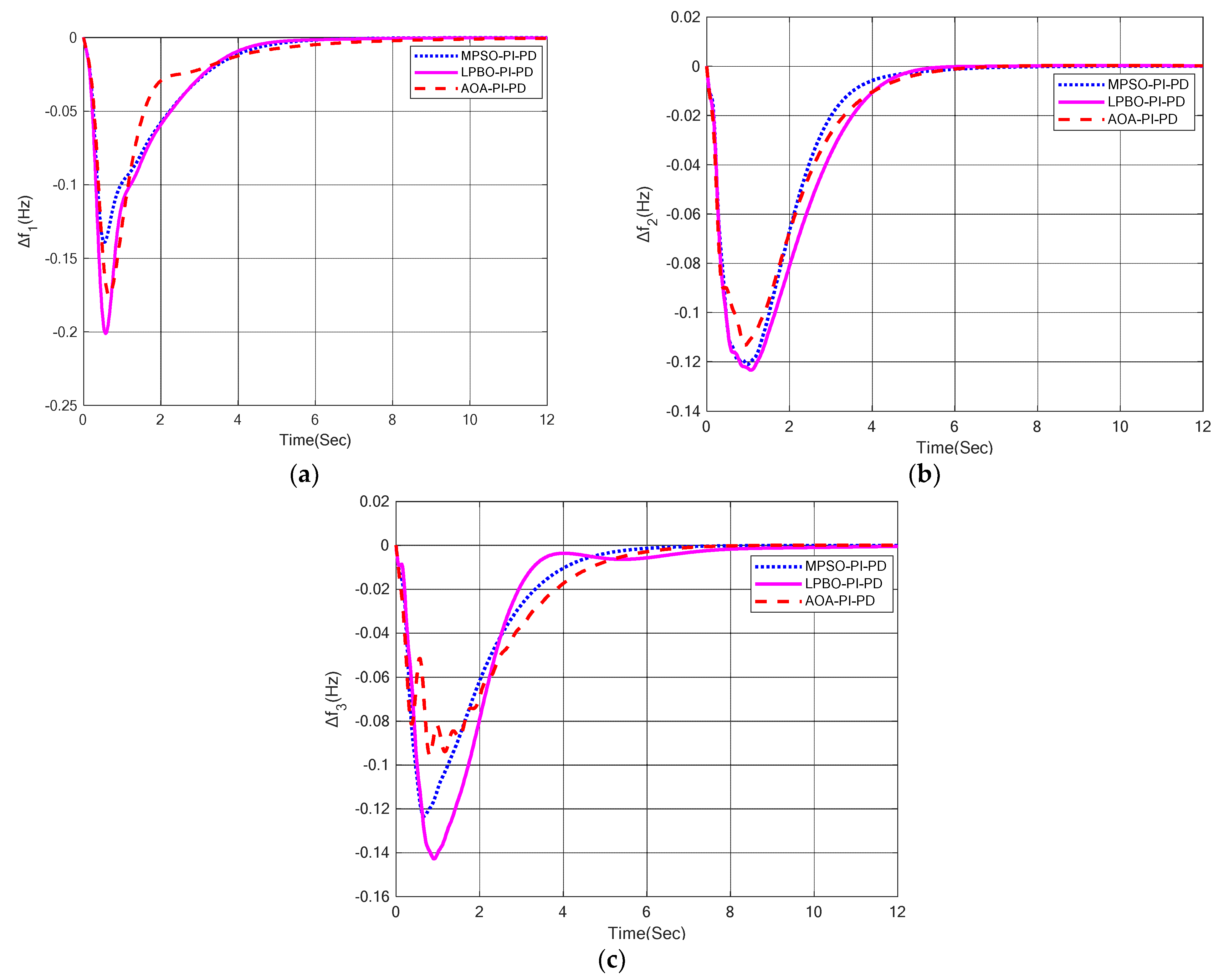
5.2. Three-Area, Three-Source System

In this section, the proposed methodology is applied to a three-area IPS model with combined LFC-AVR. The model under study is presented in Figure 12, while the model parameters are provided in Appendix B.
The optimal values of MPSO-PI-PD, LPBO-PI-PD, and AOA-PI-PD for a three-area IPS with combined LFC and AVR are given in Table 7. Figure 13 shows the frequency deviation response using MPSO-PI-PD, LPBO-PI-PD, and AOA-PI-PD control techniques in a three-area IPS, respectively.
Table 8 shows the summary of LFC responses of area-1, area-2, and area-3 using MPSO-PI-PD, LPBO-PI-PD, and AOA-PI-PD control techniques, respectively. For area-1, LPBO-PI-PD provided 14% and 31% quick settling times as compared to the MPSO-PI-PD and AOA-PI-PD control schemes, respectively. The overshoot percentage and steady state error were zero in each case.
Further, MPSO-PI-PD exhibited 30% and 20% better undershoot responses as compared to the LPBO-PI-PD and AOA-PI-PD control techniques, respectively. For area-2, LPBO-PI-PD yielded 3.3% and 11% quick settling times, as compared to the MPSO-PI-PD and AOA-PI-PD control schemes, respectively. The overshoot percentage and steady state error were zero in each case. Further, AOA-PI-PD exhibited 4.16% and 5.74% better undershoot responses as compared to the MPSO-PI-PD and LPBO-PI-PD control schemes, respectively. For area-3, MPSO-PI-PD provided 25% and 16% quick settling times as compared to the LPBO-PI-PD and AOA-PI-PD control techniques, respectively. The overshoot percentage and steady state error were again zero in each case. Further, AOA-PI-PD exhibited 22% and 34% better undershoot responses as compared to the MPSO-PI-PD and LPBO-PI-PD control schemes, respectively. Figure 14 shows the terminal voltage responses of area-1, area-2, and area-3 using MPSO-PI-PD, LPBO-PI-PD, and AOA-PI-PD control techniques in a three-area IPS, respectively.
Table 9 shows the summary of AVR responses of area-1, area-2, and area-3 using the MPSO-PI-PD, LPBO-PI-PD, and AOA-PI-PD control schemes, respectively. For area-1, AOA-PI-PD provided 26% and 2% quick rise times as compared to the MPSO-PI-PD and LPBO-PI-PD control techniques, respectively. Moreover, AOA-PI-PD yielded 38% and 29% fast settling times as compared to the MPSO-PI-PD and LPBO-PI-PD control schemes, respectively. Further, it was observed that the percentage of overshoot and steady state error were almost zero with each tuning technique. For area-2, MPSO-PI-PD offered 3% and 13% quick rise times as compared to the LPBO-PI-PD and AOA-PI-PD control techniques, respectively. Moreover, AOA-PI-PD provided 21% and 19% fast settling times as compared to the MPSO-PI-PD and LPBO-PI-PD control schemes, respectively. Further, it can be seen that the overshoot percentage and steady state error were almost zero with each tuning technique. For area-3, LPBO-PI-PD produced 64% and 73% quick rise times as compared to the MPSO-PI-PD and AOA-PI-PD control techniques, respectively. Moreover, AOA-PI-PD provided 0.3% and 5.45% fast settling times as compared to the MPSO-PI-PD and LPBO-PI-PD control schemes, respectively. Further, it can be seen that the overshoot percentage and steady state error were negligible with each tuning technique. Figure 15 shows the graphical comparison of the performance parameters of the MPSO-PI-PD, LPBO-PI-PD, and AOA-PI-PD control techniques in a three-area interconnected system.
Figure 16 shows the tie–line power responses of area-1, area-2, and area-3 using the MPSO-PI-PD, LPBO-PI-PD and AOA-PI-PD control schemes in a three-area IPS, respectively. It can be inferred that PI-PD-based control schemes including MPSO-PI-PD, LPBO-PI-PD, and AOA-PI-PD yielded satisfactory tie–line powers responses with negligible undershoots and overshoot percentages in the three-area IPS.

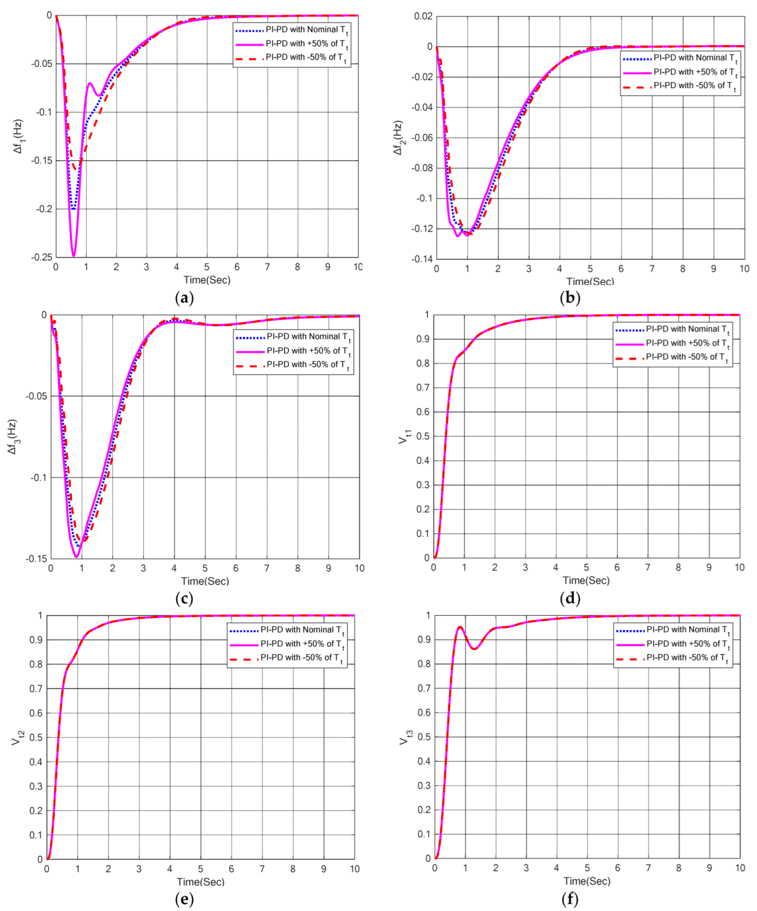
5.3. Sensitivity Analysis

In this section, the robustness of the proposed nature-inspired computation-based PI-PD control techniques were tested with large variations in the system parameters of the three-area IPS with combined LFC-AVR. The generator time constant (Tg) and turbine time constant (Tt) were varied to  ± 50% of their nominal values. The newer values of Tg and Tt after  ± 50% variations are given in Appendix B. The optimum parameters of the PI-PD control scheme were the same as those used in Case 2. The AVR and LFC responses of the PI-PD control scheme with variations in Tt and Tg are depicted in Figure 17 and Figure 18, respectively. Table 10 and Table 11 show the summary of the performance parameters of LFC and AVR responses under parametric variations. From the obtained results, it is evident the overshoot percentages and steady state error were almost zero in each case. The AVR responses are almost indistinguishable to each other, despite the variation in system parameters. Figure 19 shows the graphical comparison of the performance parameters under this scenario. It is clearly observed that the system response under  ± 50% variations was very identical to response with nominal values. This indicates that the proposed LPBO-PI-PD control technique was very realistic and robust under variations in the system parameters. These results clearly reveal that the re-tuning of the proposed controller is not necessary with large variations of at least  ± 50%.

6. Conclusions and Future Work

The multi-area IPS included numerous control areas, which are connected through the AC tie–line. The transient and steady state performance of a multi-area IPS with AVR-LFC was thoroughly investigated in this research.Nature-inspired computation including MPSO-, LPBO-, and AOA-based PI-PD control technique was proposed for the optimization of the multi-area system. From the findings of Case 1, it is concluded that all proposed schemes provided relatively better undershoot responses as compared to the NLTA-PID controller [5] for LFC. Particularly, the AOA-PI-PD control scheme exhibited 60% and 56% better undershoots in the area-1 and area-2 LFC, respectively, as compared to the NLTA-PID controller. Similarly, NLTA-PID provided 18% and 17% overshoot in the area-1 and area-2 AVR, respectively, but the proposed PI-PD control scheme completely eliminated the overshoot percentage with each tuning algorithm. The results of Case 2 reveal that LPBO-PI-PD provided 14% and 31% quick settling times in area-1, whereas 3.3% and 11% quick settling times were provided in the area-2 LFC as compared to the MPSO-PI-PD and AOA-PI-PD control techniques, respectively. In the area-3 LFC, MPSO-PI-PD provided relatively lower settling times (25% and 16%) as compared to the LPBO-PI-PD and AOA-PI-PD control schemes, respectively. MPSO-PI-PD provided relatively better undershoot (30% and 20%) in the area-1 LFC, whereas the AOA-PI-PD control technique provided better undershoot in the area-1 (4.16% and 5.74%) and area-2 (22% and 34%) LFC, respectively. Moreover, the AOA-PI-PD control scheme provided 26% and 2% quick rise times, and 38% and 29% fast settling times in the area-1 AVR as compared to the MPSO-PI-PD and LPBO-PI-PD control schemes, respectively. Further, MPSO-PI-PD provided 3% and 13% fast rise times in the area-2 AVR as compared to the LPBO-PI-PD and AOA-PI-PD control schemes, respectively. AOA-PI-PD provided 21% and 19% quick settling times in the area-2 AVR, and 0.3% and 5.45% fast settling times in the area-3 AVR as compared to the MPSO-PI-PD and AOA-PI-PD control schemes, respectively. For the area-3 AVR, LPBO-PI-PD provided 64% and 73% fast rise times as compared to the MPSO-PI-PD and AOA-PI-PD control schemes, respectively. Finally, the resilience of the PI-PD control technique was assessed by varying the system parameters (Â ± 50%), and a comprehensive sensitivity analysis was carried out to confirm its robustness. The results confirm the superiority of the proposed PI-PD control scheme when applied to multi-area IPS with combined LFC and AVR. Keeping in mind the value of the present work, IPS with a combined LFC-AVR can be analyzed by incorporating multi-source and various energy storage devices to enhance the dynamic response of the power systems. Further, neuro-fuzzy and hybrid ANN controllers can also be utilized for multi-area multi-sources IPS. It will be worth employing PI-PD, neuro-fuzzy, or hybrid ANN to multi-area IPS under nonlinearity constraints. Moreover, very recently introduced nature-inspired computing techniques such as dandelion optimization, artificial rabbits optimization, and sea-horse optimization can be explored to find the optimal parameters of controllers in such types of application.

Author Contributions

Conceptualization, T.A., S.A.M., A.T.A.; Data curation, T.A., S.A.M., A.D., H.M.; Formal analysis, T.A., S.A.M., A.D., H.M., A.T.A., I.A.H.; Investigation, A.T.A., I.A.H.; Methodology, T.A., S.A.M., A.D., H.M., A.T.A., I.A.H.; Project administration, A.T.A., I.A.H.; Resources, T.A., S.A.M., A.D., H.M.; Supervision, A.T.A., I.A.H.; Validation, T.A., S.A.M., A.D., H.M.; Visualization, A.D., H.M.,A.T.A., I.A.H.; Writing—original draft, T.A., S.A.M., A.D., H.M.; Writing—review & editing, T.A., S.A.M., A.D., H.M., A.T.A., I.A.H.; Funding Acquisition, I.A.H. All authors have read and agreed to the published version of the manuscript.

Funding

This research was funded by Norwegian University of Science and Technology.

Institutional Review Board Statement

Not applicable.

Informed Consent Statement

Not applicable.

Acknowledgments

The authors would like to acknowledge the support of Norwegian University of Science and Technology for paying the Article Processing Charges (APC) of this publication. Special acknowledgment to Automated Systems & Soft Computing Lab (ASSCL), Prince Sultan University, Riyadh, Saudi Arabia. In addition, the authors wish to acknowledge the editor and anonymous

Conflicts of Interest

The authors declare no conflict of interest.

Appendix A

Table A1. Area-2 [5].
Sr. No.Area-1Area-2
System’s ParameterValueSystem’s ParameterValue
1B11B21
2R12.4R21.2
3KG11KG21
4TG10.08TG20.12
5Kt11Kt21
6Tt10.3Tt20.15
7ΔPD10.02ΔPD20.02
8Kp1120Kp2100
9Tp120Tp210
10Ka110Ka210
11Ta10.1Ta20.1
12Ke11Ke21.5
13Te10.4Te20.6
14Kg11Kg21.5
15Tg11Tg21.5
16Ks11Ks21
17Ts10.01Ts20.01
18G11.5G61.5
19G20.3G70.3
20G30.1G80.1
21G41.4G91.4
22G50.5G100.5
23T120.545T210.545

Appendix B

Table A2. System parameters of area-1, area-2, and area-3.
Sr. No.Area-1Area-2 Area-3
System’s ParameterValueSystem’s ParameterValueSystem’s ParameterValue
1B11B21B31
2R12.4R21.20R31.20
3KG11KG21KG31
4TG10.08TG20.12TG30.12
5Kt11Kt21Kt31
6Tt10.3Tt20.15Tt30.15
7ΔPD10.02ΔPD20.02ΔPD30.02
8Kp1120Kp2100Kp3100
9Tp120Tp210Tp310
10Ka110Ka210Ka310
11Ta10.1Ta20.1Ta30.1
12Ke11Ke21.5Ke31.8
13Te10.4Te20.6Te30.8
14Kg11Kg21.5Kg31.8
15Tg11Tg21.5Tg31.8
16Ks11Ks21Ks31
17Ts10.01Ts20.01Ts30.01
18G11.5G61.5G111.5
19G20.3G70.3G120.3
20G30.1G80.1G130.1
21G41.4G91.4G141.4
22G50.5G100.5G150.5
23T120.545T210.545T310.545
24T130.545T230.545T320.545
Table A3. System parameters after  ± 50% variations in Tg and Tt.
Sr. No.Area-1Area-2 Area-3
System’s ParameterValueSystem’s ParameterValueSystem’s ParameterValue
1Tg1 (+50%)1.5Tg2 (+50%)2.25Tg3 (+50%)2.7
Tg1 (Nominal)1Tg2 (Nominal)1.5Tg3 (Nominal)1.8
Tg1 (−50%)0.5Tg2 (−50%)0.75Tg3 (−50%)0.9
2Tt1 (+50%)0.45Tt2 (+50%)0.225Tt3 (+50%)0.225
Tt1 (Nominal)0.3Tt2 (Nominal)0.15Tt3 (Nominal)0.15
Tt1 (−50%)0.15Tt2 (−50%)0.075Tt3 (−50%)0.075

References

  1. Kalyan, C.N.S.; Goud, B.S.; Reddy, C.R.; Bajaj, M.; Sharma, N.K.; Alhelou, H.H.; Siano, P.; Kamel, S. Comparative Performance Assessment of Different Energy Storage Devices in Combined LFC and AVR Analysis of Multi-Area Power System. Energies 2022, 15, 629. [Google Scholar] [CrossRef]
  2. Ghosh, A.; Ray, A.K.; Nurujjaman; Jamshidi, M. Voltage and frequency control in conventional and PV integrated power systems by a particle swarm optimized Ziegler–Nichols based PID controller. SN Appl. Sci. 2021, 3, 1–13. [Google Scholar] [CrossRef]
  3. Prakash, A.; Parida, S.K. Combined Frequency and Voltage Stabilization of Thermal-Thermal System with UPFC and RFB. In Proceedings of the 2020 IEEE 9th Power India International Conference (PIICON), Sonepat, India, 28 February–1 March 2020; pp. 1–6. [Google Scholar] [CrossRef]
  4. Fayek, H.H.; Rusu, E. Novel Combined Load Frequency Control and Automatic Voltage Regulation of a 100% Sustainable Energy Interconnected Microgrids. Sustainability 2022, 14, 9428. [Google Scholar] [CrossRef]
  5. Nahas, N.; Abouheaf, M.; Sharaf, A.M.; Gueaieb, W. A Self-Adjusting Adaptive AVR-LFC Scheme for Synchronous Generators. IEEE Trans. Power Syst. 2019, 34, 5073–5075. [Google Scholar] [CrossRef]
  6. Gupta, A.; Chauhan, A.; Khanna, R. Design of AVR and ALFC for single area power system including damping control. In Proceedings of the 2014 Recent Advances in Engineering and Computational Sciences (RAECS 2014), Chandigarh, India, 6–8 March 2014; pp. 6–8. [Google Scholar] [CrossRef]
  7. Chandrashekar, M.J.; Jayapal, R. AGC and AVR implementation in a deregulated power system using optimized controller with Renewable integrated DC link. In Proceedings of the 2019 1st International Conference on Advanced Technologies in Intelligent Control, Environment, Computing & Communication Engineering (ICATIECE 2019), Bangalore, India, 19–20 March 2019; pp. 355–364. [Google Scholar] [CrossRef]
  8. Rajbongshi, R.; Saikia, L.C. Coordinated performance of interline power flow controller and superconducting magnetic energy storage in combined ALFC and AVR system under deregulated environment. J. Renew. Sustain. Energy 2018, 10, 044102. [Google Scholar] [CrossRef]
  9. Kalyan, C.N.S.; Rao, G.S. Combined frequency and voltage stabilisation of multi-area multisource system by DE-AEFA optimised PID controller with coordinated performance of IPFC and RFBs. Int. J. Ambient Energy 2020, 1–17. [Google Scholar] [CrossRef]
  10. Kalyan, C.N.S.; Rao, G.S. Frequency and voltage stabilisation in combined load frequency control and automatic voltage regulation of multiarea system with hybrid generation utilities by AC/DC links. Int. J. Sustain. Energy 2020, 39, 1009–1029. [Google Scholar] [CrossRef]
  11. Sahani, A.K.; Raj, U.; Shankar, R.; Mandal, R.K. Firefly Optimization Based Control Strategies for Combined Load Frequency Control and Automatic Voltage Regulation for Two-Area Interconnected Power System. Int. J. Electr. Eng. Inform. 2019, 11, 747–758. [Google Scholar] [CrossRef]
  12. Lal, D.K.; Barisal, A.K. Combined load frequency and terminal voltage control of power systems using moth flame optimization algorithm. J. Electr. Syst. Inf. Technol. 2019, 6, 1–24. [Google Scholar] [CrossRef]
  13. Grover, H.; Verma, A.; Bhatti, T.S. Load frequency control & automatic voltage regulation for a single area power system. In Proceedings of the 2020 IEEE 9th Power India International Conference (PIICON 2020), Sonepat, India, 28 February–1 March 2020; pp. 1–5. [Google Scholar] [CrossRef]
  14. Salman, G.; Jafar, A.S.; Ismael, A.I. Application of artificial intelligence techniques for LFC and AVR systems using PID controller. Int. J. Power Electron. Drive Syst. (IJPEDS) 2019, 10, 1694–1704. [Google Scholar] [CrossRef]
  15. Kouba, N.E.Y.; Menaa, M.; Hasni, M.; Boudour, M. Optimal control of frequency and voltage variations using PID controller based on Particle Swarm Optimization. In Proceedings of the 2015 4th International Conference on Systems and Control (ICSC), Sousse, Tunisia, 28–30 April 2015; pp. 424–429. [Google Scholar] [CrossRef]
  16. Safiullah, S.; Rahman, A.; Lone, S.A. State-observer based IDD controller for concurrent frequency-voltage control of a hybrid power system with electric vehicle uncertainties. Int. Trans. Electr. Energy Syst. 2021, 31, e13083. [Google Scholar] [CrossRef]
  17. Mohammadikia, R.; Nikoofard, A.; Tavakoli-Kakhki, M. Application of MPC for an automatic voltage regulator and load frequency control of interconnected power system. In Proceedings of the 2020 28th Iranian Conference on Electrical Engineering (ICEE), Tabriz, Iran, 4–6 August 2020. [Google Scholar] [CrossRef]
  18. Eke, I.; Saka, M.; Gozde, H.; Arya, Y.; Taplamacioglu, M.C. Heuristic optimization based dynamic weighted state feedback approach for 2DOF PI-controller in automatic voltage regulator. Eng. Sci. Technol. Int. J. 2021, 24, 899–910. [Google Scholar] [CrossRef]
  19. Wagle, R.; Sharma, P.; Sharma, C.; Gjengedal, T.; Pradhan, C. Bio-inspired hybrid BFOA-PSO algorithm-based reactive power controller in a standalone wind-diesel power system. Int. Trans. Electr. Energy Syst. 2021, 31. [Google Scholar] [CrossRef]
  20. Prasad, S.; Purwar, S.; Kishor, N. Load frequency regulation using observer based non-linear sliding mode control. Int. J. Electr. Power Energy Syst. 2018, 104, 178–193. [Google Scholar] [CrossRef]
  21. Panigrahi, N.; Nayak, A.; Mishra, S.R. Morphology of the Alumina Nanoparticles for the Arrangement of the KF Stacked Nano–γ–Al2O3 as Catalyst for Conversion of Biomass to Fuel. In Advances in Energy Technology; Springer: Berlin/Heidelberg, Germany, 2021; pp. 125–132. [Google Scholar]
  22. Daraqz, A.; Malik, S.A.; Waseem, A.; Azar, A.T.; Haq, I.U.; Ullah, Z.; Aslam, S. Automatic generation control of multi-source interconnected power system using FOI-TD controller. Energies 2021, 14, 5867. [Google Scholar] [CrossRef]
  23. Guo, J. Application of a novel adaptive sliding mode control method to the load frequency control. Eur. J. Control 2020, 57, 172–178. [Google Scholar] [CrossRef]
  24. Arya, Y.; Kumar, N. Design and analysis of BFOA-optimized fuzzy PI/PID controller for AGC of multi-area traditional/restructured electrical power systems. Soft Comput. 2016, 21, 6435–6452. [Google Scholar] [CrossRef]
  25. Daraz, A.; Malik, S.A.; Mokhlis, H.; Haq, I.U.; Laghari, G.F.; Mansor, N.N. Fitness Dependent Optimizer-Based Automatic Generation Control of Multi-Source Interconnected Power System with Non-Linearities. IEEE Access 2020, 8, 100989–101003. [Google Scholar] [CrossRef]
  26. Raj, U.; Shankar, R. Deregulated Automatic Generation Control using Novel Opposition-based Interactive Search Algorithm Cascade Controller Including Distributed Generation and Electric Vehicle. Iran. J. Sci. Technol. Trans. Electr. Eng. 2020, 44, 1233–1251. [Google Scholar] [CrossRef]
  27. Kose, E. Optimal Control of AVR System with Tree Seed Algorithm-Based PID Controller. IEEE Access 2020, 8, 89457–89467. [Google Scholar] [CrossRef]
  28. Kalyan, C.N.S.; Goud, B.S.; Reddy, C.R.; Ramadan, H.S.; Bajaj, M.; Ali, Z.M. Water Cycle Algorithm Optimized Type II Fuzzy Controller for Load Frequency Control of a Multi-Area, Multi-Fuel System with Communication Time Delays. Energies 2021, 14, 5387. [Google Scholar] [CrossRef]
  29. Tripathy, S.; Debnath, M.K.; Kar, S.K. Optimal Design of Fractional Order 2DOF-PID Controller for Frequency Control in Interconnected System. In Green Technology for Smart City and Society; Springer: Singapore, 2020; pp. 23–33. [Google Scholar] [CrossRef]
  30. Sahu, P.C.; Prusty, R.C.; Sahoo, B.K. Modified sine cosine algorithm-based fuzzy-aided PID controller for automatic generation control of multiarea power systems. Soft Comput. 2020, 24, 12919–12936. [Google Scholar] [CrossRef]
  31. Ajithapriyadarsini, S.; Mary, P.M.; Iruthayarajan, M.W. Automatic generation control of a multi-area power system with renewable energy source under deregulated environment: Adaptive fuzzy logic-based differential evolution (DE) algorithm. Soft Comput. 2019, 23, 12087–12101. [Google Scholar] [CrossRef]
  32. Çelik, E. Design of new fractional order PI–fractional order PD cascade controller through dragonfly search algorithm for advanced load frequency control of power systems. Soft Comput. 2020, 25, 1193–1217. [Google Scholar] [CrossRef]
  33. Daraz, A.; Malik, S.A.; Mokhlis, H.; Haq, I.U.; Zafar, F.; Mansor, N.N. Improved-Fitness Dependent Optimizer Based FOI-PD Controller for Automatic Generation Control of Multi-Source Interconnected Power System in Deregulated Environment. IEEE Access 2020, 8, 197757–197775. [Google Scholar] [CrossRef]
  34. Daraz, A.; Malik, S.A.; Haq, I.U.; Khan, K.B.; Laghari, G.F.; Zafar, F. Modified PID controller for automatic generation control of multi-source interconnected power system using fitness dependent optimizer algorithm. PLoS ONE 2020, 15, e0242428. [Google Scholar] [CrossRef] [PubMed]
  35. Biswas, S.; Roy, P.K.; Chatterjee, K. FACTS-based 3DOF-PID Controller for LFC of Renewable Power System Under Deregulation Using GOA. IETE J. Res. 2021, 1–14. [Google Scholar] [CrossRef]
  36. Fathy, A.; Kassem, A.M.; Abdelaziz, A.Y. Optimal design of fuzzy PID controller for deregulated LFC of multi-area power system via mine blast algorithm. Neural Comput. Appl. 2018, 32, 4531–4551. [Google Scholar] [CrossRef]
  37. Daraz, A.; Malik, S.A.; Azar, A.T.; Aslam, S.; Alkhalifah, T.; Alturise, F. Optimized Fractional Order Integral-Tilt Derivative Controller for Frequency Regulation of Interconnected Diverse Renewable Energy Resources. IEEE Access 2022, 10, 43514–43527. [Google Scholar] [CrossRef]
  38. Zhao, S.; Zhang, T.; Ma, S.; Chen, M. Dandelion Optimizer: A nature-inspired metaheuristic algorithm for engineering applications. Eng. Appl. Artif. Intell. 2022, 114. [Google Scholar] [CrossRef]
  39. Alsattar, H.A.; Zaidan, A.A.; Zaidan, B.B. Novel meta-heuristic bald eagle search optimisation algorithm. Artif. Intell. Rev. 2019, 53, 2237–2264. [Google Scholar] [CrossRef]
  40. Qais, M.H.; Hasanien, H.M.; Alghuwainem, S. Transient search optimization: A new meta-heuristic optimization algorithm. Appl. Intell. 2020, 50, 3926–3941. [Google Scholar] [CrossRef]
  41. Rahman, C.M.; Rashid, T.A. A new evolutionary algorithm: Learner performance based behavior algorithm. Egypt. Inform. J. 2020, 22, 213–223. [Google Scholar] [CrossRef]
  42. Fathy, A.; Alharbi, A.G.; Alshammari, S.; Hasanien, H.M. Archimedes optimization algorithm based maximum power point tracker for wind energy generation system. Ain Shams Eng. J. 2021, 13, 101548. [Google Scholar] [CrossRef]
  43. Zou, H.; Li, H. Tuning of PI–PD controller using extended non-minimal state space model predictive control for the stabilized gasoline vapor pressure in a stabilized tower. Chemom. Intell. Lab. Syst. 2015, 142, 1–8. [Google Scholar] [CrossRef]
  44. Raja, G.L.; Ali, A. New PI-PD Controller Design Strategy for Industrial Unstable and Integrating Processes with Dead Time and Inverse Response. J. Control. Autom. Electr. Syst. 2021, 32, 266–280. [Google Scholar] [CrossRef]
  45. Kaya, I. Optimal PI–PD Controller Design for Pure Integrating Processes with Time Delay. J. Control. Autom. Electr. Syst. 2021, 32, 563–572. [Google Scholar] [CrossRef]
  46. Irshad, M.; Ali, A. Robust PI-PD controller design for integrating and unstable processes. IFAC-PapersOnLine 2020, 53, 135–140. [Google Scholar] [CrossRef]
  47. Peram, M.; Mishra, S.; Vemulapaty, M.; Verma, B.; Padhy, P.K. Optimal PI-PD and I-PD Controller Design Using Cuckoo Search Algorithm. In Proceedings of the 5th International Conference on Signal Processing and Integrated Networks, Delhi, India, 22–23 February 2018; pp. 643–646. [Google Scholar] [CrossRef]
  48. Deniz, F.N.; Yüce, A.; Tan, N. Tuning of PI-PD Controller Based on Standard Forms for Fractional Order Systems. J. Appl. Nonlinear Dyn. 2018, 8, 5–23. [Google Scholar] [CrossRef]
  49. Zheng, M.; Huang, T.; Zhang, G. A New Design Method for PI-PD Control of Unstable Fractional-Order System with Time Delay. Complexity 2019, 2019, 1–12. [Google Scholar] [CrossRef]
  50. Ali, T.; Adeel, M.; Malik, S.A.; Amir, M. Stability Control of Ball and Beam System Using Heuristic Computation Based PI-D and PI-PD Controller. Tech. J. Univ. Eng. Technol. 2019, 24, 21–29. [Google Scholar]
  51. Tian, D.; Shi, Z. MPSO: Modified particle swarm optimization and its applications. Swarm Evol. Comput. 2018, 41, 49–68. [Google Scholar] [CrossRef]
Figure 1. (a) Single-area AVR−LFC [5]. (b) Connections of two-area tie–line.
Sustainability 14 12162 g001aSustainability 14 12162 g001b
Figure 2. Proposed control methodology with combined LFC−AVR system.
Sustainability 14 12162 g002
Figure 3. Flow chart of LPBO algorithm.
Sustainability 14 12162 g003
Figure 4. Flow chart of AOA.
Sustainability 14 12162 g004
Figure 5. Flow chart of MPSO algorithm.
Sustainability 14 12162 g005
Figure 6. Two-area IPS with combined LFC−AVR.
Sustainability 14 12162 g006aSustainability 14 12162 g006b
Figure 7. Tie–line connection.
Sustainability 14 12162 g007
Figure 8. LFC response with PI−PD control scheme. (a) Δf1; (b) Δf2.
Sustainability 14 12162 g008
Figure 9. AVR response with PI-PD control scheme. (a) Vt1; (b) Vt2.
Sustainability 14 12162 g009
Figure 10. Tie–line power response in two−area IPS with combined LFC−AVR.
Sustainability 14 12162 g010
Figure 11. Graphical comparison of performance parameters. (a) Δf1; (b) Δf2; (c) Vt1; (d) Vt2.
Sustainability 14 12162 g011
Figure 12. Three−area IPS with combined LFC−AVR.
Sustainability 14 12162 g012aSustainability 14 12162 g012b
Figure 13. LFC response with PI−PD control scheme. (a) Δf1; (b) Δf2; (c) Δf3.
Sustainability 14 12162 g013
Figure 14. AVR response with PI-PD control scheme. (a) Vt1; (b) Vt2; (c) Vt3.
Sustainability 14 12162 g014aSustainability 14 12162 g014b
Figure 15. Graphical comparison of performance parameters. (a) Δf1; (b) Δf2; (c) Δf3;(d) Vt1; (e) Vt2; (f) Vt3.
Sustainability 14 12162 g015
Figure 16. Tie−line power responses with PI−PD control scheme. (a) ΔPtie1; (b) ΔPtie2; (c) ΔPtie3.
Sustainability 14 12162 g016
Figure 17. LFC and AVR responses with variations in Tt. (a) Δf1 in area−1; (b) Δf2 in area−2; (c) Δf3 in area−3; (d) Vt1 in area−1; (e) Vt2 in area−2 and (f) Vt3 in area−3.
Sustainability 14 12162 g017
Figure 18. LFC and AVR responses with variations in Tg. (a) Δf1 in area−1; (b) Δf2 in area−2; (c) Δf3 in area−3; (d) Vt1 in area−1; (e) Vt2 in area−2 and (f) Vt3 in area−3.
Sustainability 14 12162 g018
Figure 19. Graphical comparison of performance parameters in three-area IPS with variations in Tg and Tt. (a) Settling time; (b) undershoot.
Sustainability 14 12162 g019
Table 1. Literature on ALR-LFC.
ReferenceYearResearch AreaControllerTuning SchemesArea/SystemNonlinearitiesAdditional Incorporation
[2]2021AVR-LFCPIDPSO-ZNTwo Area--
[3]2020AVR-LFCPI, PIDFCSATwo Area-RFBs, UPFC
[4]2022AVR-LFCPIDADPOTwo Area -
[5]2019AVR-LFCPIDNLTASingle Area--
[6]2014AVR-LFCPINot givenSingle Area-Damper Winding
[7]2019AVR-LFCPID, FLCFuzzy LogicTwo Area-DC Link,
Deregulated Environment
[8]2018AVR-LFCPIDF, PIDµFLSATwo AreaGDB, GRCSMES, IPFC,
Deregulated Environment
[9]2020AVR-LFCPIDDE-AEFATwo AreaGRCIPFC and RFBs
[10]2020AVR-LFCPIDDE-AEFATwo AreaGRCHVDC link with
the existing AC tie-line
[11]2019AVR-LFCPIDFOTwo Area--
[12]2019AVR-LFCFO-PIDMFOTwo AreaGDB, BD-
[13]2020AVR-LFCPIHIL
Strategy
Single Area--
[14]2019AVR-LFCPIDFA, GA, PSOSingle Area--
[15]2015AVR-LFCPIDPSOTwo Area--
[16]2018AVR-LFCSO-IDD MBOTwo AreaGRC, GDB-
[17]2020AVR-LFCMPCMPCTwo Area--
[18]2020AVR2DOF state-feedback PI controlVSA, WOA, SCA
GWO, SSA, WCA
AVR for Synchronous Generator--
[19]2021AVRPIHybrid BFOA-PSOStandalone Wind–Diesel Power System-STATCOM
[20]2019LFCObserver-based nonlinear sliding mode
control
LMITwo AreaGRC, GDB-
[21]2021LFCPIDMOLTwo AreaGDB-
Proposed Work2022AVR-LFCPI-PDAOA, LPBO, MPSOTwo Area,
Three Area
--
Table 2. Nomenclature.
AcronymDefinitionAcronymDefinition
AOAArchimedes optimization algorithmIPSInterconnected power system
NLTANonlinear threshold-accepting algorithmLPBOLearner performance-based behavior optimization
AVRAutomatic voltage regulatorΔPtieTie-line power deviation
PI-PDProportional integral–proportional derivativeVtTerminal voltage
MPSOModified particle swarm optimizationLFCLoad frequency control
RiSpeed regulationΔfFrequency deviation
KGGovernor gainBArea bias factor
TGTime constant of governorΔPDLoad deviation
KaAmplifier gainKtTurbine gain
TaTime constant of amplifierTtTime constant of turbine
KgGenerator gainKeExciter gain
TgTime constant of generatorTeTime constant of exciter
KpPower system gainΔXGValve position of governor
TpTime constant of power systemΔPGDeviation in the output of generator
T12, T21Tie-line synchronizing time constantsKiCoupling coefficient of AVR-LFC loops
Table 3. Parameters of optimization techniques.
MPSOLPBOAOA
ParameterValueParameterValueParameterValue
Population size20Population size20Population size20
Iterations10Iterations10Iterations10
Inertia Weight Damping Ratio1Crossover Percentage0.7C1 (constant)2
Personal Learning Coefficient2.74Mutation Percentage0.3C2 (constant)6
Global Learning Coefficient2.88Mutation Rate0.03C3 (constant)2
Max. Velocity Limit0.2Number of Mutants6C4 (constant)0.5
Min. Velocity Limit−0.2Number of Offspring14Range of Normalization (u,l)0.9, 0.1
Table 4. Optimal values of controller parameters (area-2).
AreaController ParametersNLTA-PID [5]Controller ParametersProposed Control Schemes
MPSO-PI-PDLPBO-PI-PDAOA-PI-PD
Area-1Kp11.995Kp11.0611.0641.61
Ki11.943Ki10.6301.3961.512
Kd11.079Kp21.1621.0711.88
Kp21.994Kd11.6211.7951.263
Ki21.295Kp31.0631.8501.01
Kd21.107Ki21.4190.7721.68
--Kp40.8120.1400.68
--Kd20.2830.4830.37
Area-2Kp31.956Kp50.5640.9650.90
Ki31.919Ki30.7920.6670.67
Kd30.655Kp60.7750.6701.44
Kp41.283Kd31.1060.6161.60
Ki40.586Kp71.9031.5221.50
Kd40.819Ki41.3761.3251.85
--Kp80.7990.5070.74
--Kd40.8220.5260.52
ITSE2.84ITSE0.2500.1640.1892
Table 5. LFC responses (area-2).
Area-1Area-2
Control SchemeSettling Time% OvershootUndershoots-s
Error
Settling Time% OvershootUndershoots-s
Error
NLTA-PID [5]2.12040.0005−0.28502.5920−0.2750
MPSO-PI-PD4.54070−0.1304.920−0.1350
LPBO-PI-PD6.94780.005−0.13504.0430−0.170
AOA-PI-PD6.67520−0.11504.690−0.120
Table 6. AVR responses (area-2).
Control SchemeArea-1Area-2
Rise TimeSettling Time% Overshoots-s
Error
Rise TimeSettling Time% Overshoots-s
Error
NLTA-PID [5]0.12871.2418.8000.1540.88717.750
MPSO-PI-PD0.65323.30001.0773.173.2971 × 10−40
LPBO-PI-PD0.45461.220.2800.4641.38100
AOA-PI-PD0.6101.230.2700.4351.49900
Table 7. Optimal values of controller parameters (area-3).
AreaController ParametersProposed Control Schemes
MPSO-PI-PDLPBO-PI-PDAOA-PI-PD
Area-1Kp11.09950.661.51
Ki11.10280.591.29
Kp21.27370.96−0.38
Kd10.8310.530.55
Kp31.53711.560.88
Ki21.9651.621.91
Kp41.25430.851.13
Kd20.59360.560.5
Area-2Kp51.11060.770.86
Ki30.90760.610.71
Kp60.86391.481.55
Kd31.31181.030.86
Kp71.79171.681.91
Ki41.82861.571.97
Kp80.90680.831.074
Kd40.68820.731.071
Area-3Kp90.79140.781.9
Ki51.07951.121.26
Kp101.27410.661.64
Kd50.85811.560.42
Kp111.22821.291.63
Ki61.43261.31.69
Kp120.95270.771.43
Kd60.58740.451.33
ITSE 0.35070.344850.4853
Table 8. LFC responses (area-3).
AreaControl SchemeSettling Time% OvershootUndershoots-s
Error
Area-1MPSO-PI-PD5.430−0.140
LPBO-PI-PD4.650−0.200
AOA-PI-PD6.730−0.1750
Area-2MPSO-PI-PD5.040−0.1200
LPBO-PI-PD4.870−0.1220
AOA-PI-PD5.460−0.1150
Area-3PSO-PI-PD5.400−0.1220
LPBO-PI-PD7.160−0.1430
AOA-PI-PD6.400−0.0950
Table 9. AVR responses (area-3).
AreaControl SchemeRise TimeSettling Time% Overshoots-s
Error
Area-1MPSO-PI-PD1.533.485.8225 × 10−60
LPBO-PI-PD1.153.014.5973 × 10−40
AOA-PI-PD1.132.150.0830
Area-2MPSO-PI-PD0.952.4400
LPBO-PI-PD0.982.3700
AOA-PI-PD1.091.920.370
Area-3MPSO-PI-PD1.323.3000
LPBO-PI-PD0.483.480.0010
AOA-PI-PD1.753.2900
Table 10. Settling time responses of PI-PD control scheme with variations in system parameters.
Parameters/VariationSettling Time (LFC and AVR)
Δf1Δf2Δf3Vt1Vt2Vt3
Nominal Tg, Tt4.654.877.163.012.373.48
Tg1, Tg2, Tg3/+50%4.604.767.022.742.113.56
Tg1, Tg2, Tg3/−50%4.714.957.323.252.593.56
Tt1, Tt2, Tt3/+50%4.635.017.183.032.383.48
Tt1, Tt2, Tt3/−50%4.604.717.112.992.363.48
Table 11. Overshoot and undershoot responses of PI-PD control scheme with variations in system parameters.
Parameters/Variation%Overshoot (LFC and AVR)%Undershoot (LFC)
Δf1Δf2Δf3Vt1Vt2Vt3Δf1Δf2Δf3
Nominal Tg, Tt000000−0.2−0.122−0.143
Tg1, Tg2, Tg3/+50%000003.4−0.185−0.13−0.155
Tg1, Tg2, Tg3/−50%000000−0.215−0.125−0.13
Tt1, Tt2, Tt3/+50%000000−0.245−0.125−0.15
Tt1, Tt2, Tt3/−50%000000−0.16−0.125−0.135
Publisher’s Note: MDPI stays neutral with regard to jurisdictional claims in published maps and institutional affiliations.

