
Nonlinear Modelling and Control of a Power Smoothing System for a Novel Wave Energy Converter Prototype


1
Graduate Center of Engineering and Design (GC-ED), Technical University of Munich (TUM) and SINN Power GmbH, 85748 Munich, Germany
2
Laboratory for Mechatronic and Renewable Energy Systems (LMRES), Hochschule München (HM) University of Applied Sciences, 80335 Munich, Germany
*
Author to whom correspondence should be addressed.
Sustainability 2022, 14(21), 13708; https://0-doi-org.brum.beds.ac.uk/10.3390/su142113708
Submission received: 9 August 2022
/
Revised: 6 October 2022
/
Accepted: 19 October 2022
/
Published: 22 October 2022
(This article belongs to the Special Issue Intelligent Mechatronic and Renewable Energy Systems)
Abstract
:This contribution presents the control of the electrical system of a Wave Energy Converter (WEC) prototype developed by SINN Power. Due to the movement of the waves, the generated power has a very high fluctuation with a period of a few seconds. To be able to use this power, it has to be smoothed. The used Energy Storage System (ESS) is a supercapacitor bank, which is directly connected to the DC-link. Therefore, the DC-link voltage has to fluctuate according to the generated power, to charge and discharge the capacitors. The smoothed power is used to charge batteries with a DC/DC converter, which is typically used for photovoltaic applications. The DC-link voltage can be controlled with the current through the DC/DC converter, yielding a nonlinear control system where a stability analysis is carried out to prove a safe and stable operation. Measurement results at the prototype under typical sea conditions are presented, which fit the simulation results. With the presented control system, smooth power output can be guaranteed.
1. Motivation and Problem Statement
Due to the climate crisis, renewable energy resources must play a fundamental role in the future energy system. As wave energy has a higher continuity than both solar and wind energy, it has the potential to become an important part of the energy generation of tomorrow ([1] Section 2.2), [2,3].
SINN Power has developed a Wave Energy Converter (WEC) and installed their third prototype. The WEC works as a point absorber. The prototype of a single module of the power plant is mounted on the harbour wall of Heraklion on the Greek island of Crete, as shown in Figure 1. It consists of a floating buoy, a rod and generator units.
A common challenge for wave energy converters is power smoothing. The fluctuations of ocean waves range from a second-by-second basis (from wave to wave), to hourly, daily and seasonal fluctuations [4,5]. The generated electrical power fluctuates with the waves’ movement and a period of a few seconds. In [6], optimal control of a WEC is proposed, where it is assumed that power smoothing is already handled internally in the mechanical or electrical power take-off components of the WEC. However, a lot of effort is required to smooth the second-by-second fluctuations. It can be shown that an arrangement of multiple WECs in a wave energy farm leads to a more uniform overall power, due to their spatial positioning and the resulting time delay of the waves at the single WEC modules [7,8,9,10]. The integration of WEC farms into offshore wind energy farms also offers strong synergies [11,12,13].
Despite the general challenge of power smoothing, in particular, for the proposed novel WEC prototype, the most power is generated when the wave pushes the floating buoy upwards. In the downward movement, only the gravitation force of the floating buoy and the rod produce power. During the reversal points, where the speed is zero, the power is zero as well. Hence, the electrical power must be smoothed before it is fed into the grid. In the grid, fluctuating power could cause instability, like large voltage variations, flickers and harmonics [14,15,16,17].
To smooth this fluctuation with battery storage, it must be sized for the peak current, which can be costly. Furthermore, the very high number of cycles reduces the lifetime of the battery. When using a hybrid system consisting of batteries and supercapacitors, the battery storage can be smaller and will last longer. The supercapacitors, with their high power density, can withstand the high current peaks, while the batteries, with their high energy density, can provide or store the power over a long period of time [18,19,20].
In renewable energy applications, supercapacitors are used to smooth the power variations and to fulfil the grid requirements, such as the Low Voltage Ride Through (LVRT) capability [18,21,22]. In [17,23,24,25,26], different technologies such as flywheel, Superconducting Magnetic Energy Storage (SMES) and a hybrid system with a combination of flywheel and battery were considered to smooth the output power of a wave energy application.
Because of their simplicity, supercapacitors are often chosen for the short-time Energy Storage System (ESS) in WECs. In [16,27,28,29,30,31], the supercapacitors are connected to the DC-link with a bidirectional DC/DC converter. This allows separate control of power flow and DC-link voltage, which also leads to better utilization of the storage. In [32], a hybrid ESS with Li-ion batteries and supercapacitors is used to smooth the output power of WEC that generates a bidirectional power flow, due to its control strategy.
However, the publications mentioned above lack a detailed model and explanation of the control system for power smoothing, which will be addressed here. In this work, the supercapacitor is directly connected to the DC-link, due to its simplicity and the absence of a bidirectional DC/DC converter, at the time the prototype had to be installed. A unidirectional DC/DC converter is used to charge the battery storage.
The contributions of this paper are: (i) a detailed explanation of the electrical system of a novel full-sized WEC, (ii) introduction of a new DC-link voltage controller with the additional objective of power smoothing; furthermore, (iii) derivation of a nonlinear state-space model, (iv) a stability analysis is conducted to proof a safe and reliable operation, (v) validation by real measurement results at the prototype under harsh sea conditions and (vi) comparison of the measurement results with the simulation to prove the correctness of the model.
In the following, the control of the electrical system of the single WEC module is presented. First, the electrical system with its components will be explained, followed by a stability analysis in Section 4. Section 3 describes how the power smoothing is done and how the control of the DC-link works. Finally, in Section 5, the measurement results are presented and compared to the simulation results.
2. Electrical System of the Wave Energy Converter
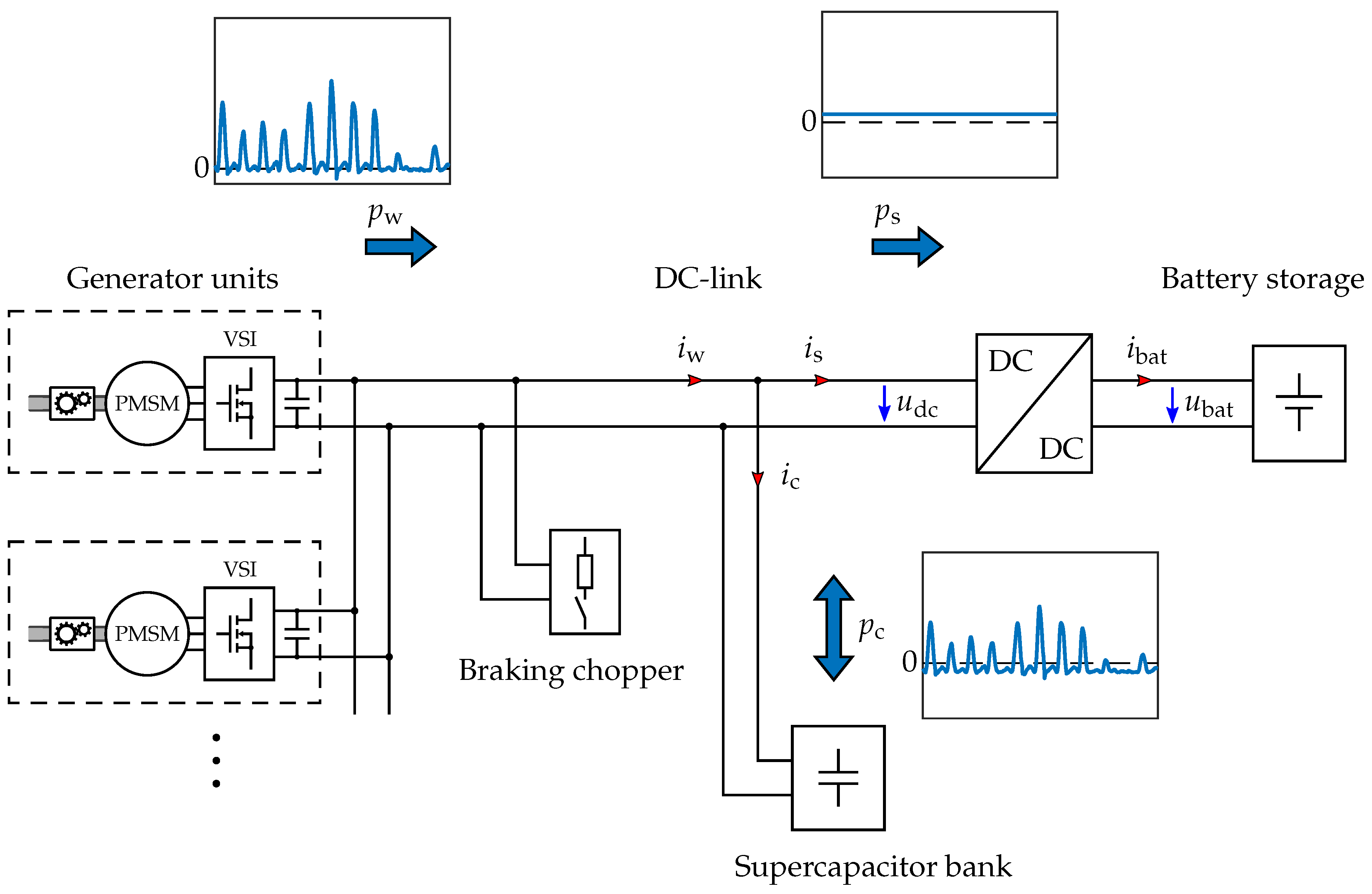
Figure 2 shows the simplified schematic of the WEC’s electrical system as it is realised at the test site. The supercapacitor bank and the DC/DC converter are described in more detail in the following.
The generated energy is used to charge batteries. This allows for more flexibility and is more tolerant to fluctuations, which can occur during the tests of different control strategies. The energy in the batteries is used for various peripherals, which ensures that the batteries do not become fully charged, so that the energy generated by the WEC can always be stored. The charging is done by means of a unidirectional DC/DC converter, connected to the DC-link.
Power smoothing requires energy storage that stores the power peaks in the upwards movement and releases it during time periods of less power generation. Here, a supercapacitor bank is used, which is directly connected in parallel to the DC-link.
A braking chopper is integrated as a safety measure to dissipate excess energy. This prevents the voltage to rise over a specified limit. The chopper works completely independently and is therefore considered a disturbance to the control system. Moreover, if the control system is working correctly, the chopper does not need to intervene.
2.1. Generator Units
The floating buoy of the WEC swims on the water and moves up and down with each wave. The rod is attached to the buoy and moves with it. Over the rolls of multiple generator units, which are pressed on the rod with springs, the vertical movement is converted into a rotary movement. The main components of the generator unit are a gearbox, a Permanent-Magnet Synchronous Machine (PMSM), and a Voltage Source Inverter (VSI). The rated power of one generator unit is about .
The current through the PMSM is controlled by the VSI, which allows the torque of the generator rolls to be controlled. Thus, the mechanical power can be converted into electrical power by braking the movement of the rod. All DC outputs of the generator units are connected in parallel to the DC-link, which is also the connection to the shore.
The maximum allowed DC-link voltage is , due to the voltage rating of the electrical components in the VSI. For additional safety, the voltage is limited to . The VSI requires minimal voltage for the current control, which is related to the rotational speed of the PMSM. Here, the voltage should not fall below . The nominal voltage is .
The generator unit and the implemented current control were presented and optimized in a previous work [33].
2.2. Supercapacitor Bank
A supercapacitor, also called an ultracapacitor or Electric Double-Layer Capacitor (EDLC), is characterized by its very high capacitance, reaching up to several . Consequently, the voltage rating is rather low, typically under . The electrical parameters of the used supercapacitor cell are listed in Table 1.
To achieve more dielectric strength, the capacitors can be connected in series. Due to component tolerances and ageing, different voltages can occur at the single capacitors during charging and discharging. Hence, to avoid overvoltage, the cells must be balanced [35,36].
Here, the maximum allowed DC-link voltage is . Therefore, at least 149 cells in series are necessary. The developed supercapacitor bank consists of in series connected cells, divided into 16 modules with 10 cells each.
The balancing of the cells is achieved by a parallel connection of a balancing circuit to each cell. It consists of a resistor and a serially connected bipolar transistor. An analogue circuit compares the voltage of two consecutive cells and uses the transistor to control the current through the resistor. The supercapacitor bank is shown in Figure 3.
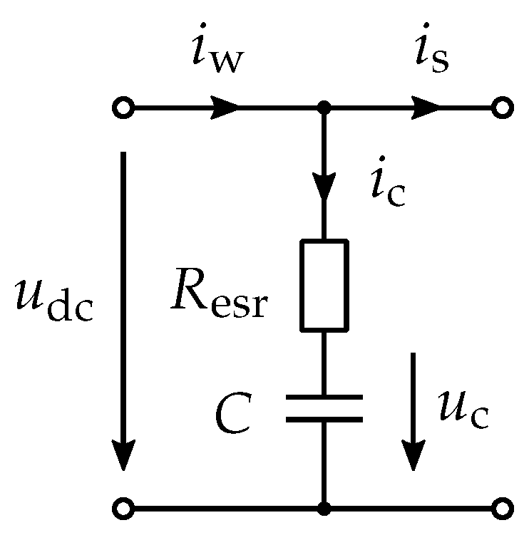
The bank is modelled as an RC model, as shown in Figure 4. More detailed models, such as the RC parallel branch model, are not considered, as the dynamic behaviour of the RC model is sufficient for this case [37,38]. The current induced by self-discharging and balancing is neglected in the model, as it occurs over a longer period of time during which several waves appear, and is, therefore, not relevant to the dynamic behaviour.
Due to the series connection of the cells, the equivalent series resistors of each cell are summed up, resulting in the overall resistance
The overall capacitance C is given by
Assuming that each cell has the same capacitance, the calculation can be simplified to
The VSI of the generator units has a DC-link capacitor to stabilize the voltage at their terminals. However, they are very small compared to the capacitance of the supercapacitor bank and can be neglected. The other parameters are calculated in the same way, leading to the electrical parameters of the supercapacitor bank, listed in Table 2.
Due to the limits of the DC-link voltage , the stored energy in the supercapacitors cannot be utilized entirely. The maximally available energy is
which can be used for power smoothing and represent about 38% of the possibly stored energy. There are several methods to estimate the necessary storage size [27,39,40]. For a rough estimation, it is assumed that the WEC produces the maximal power over , which is a typical duration of a power pulse. In the prototype, 8 generator units with a rated power of are installed. To estimate the worst case, it is assumed that all generators deliver their rated power over two seconds. Subtracting a realistic average power of for this condition results in energy of about , which can be covered by the installed supercapacitor bank (see Equation (4)). This energy needs to be stored during the assumed two seconds and is then continuously discharged until the next wave arrives. Thus, a power fluctuation of about 7 times the average power can be suppressed.
2.3. DC/DC Converter
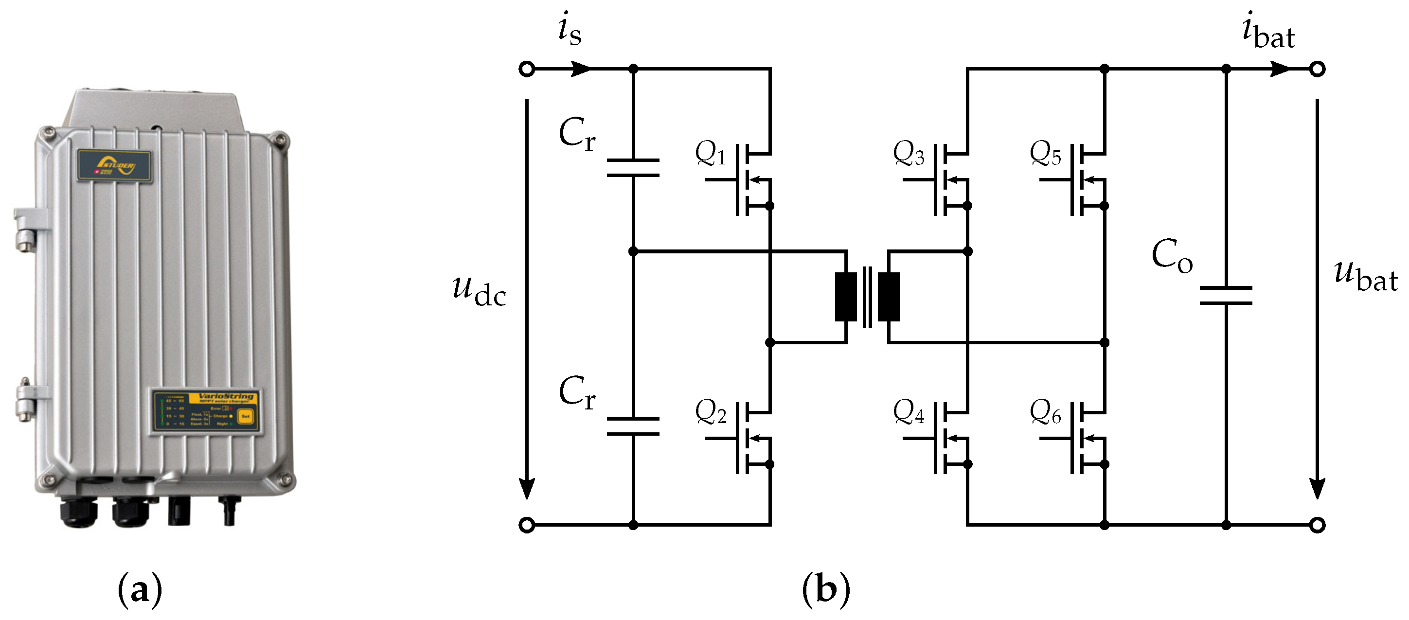
Figure 5a shows the DC/DC converter VarioString VS-70, made by Studer Innotec, which is used to charge 48-V-batteries from the DC-link. The VarioString is designed to be installed in a photovoltaic application, however, the specifications, listed in Table 3, are perfectly suited for the application considered here. The very high efficiency is made possible by an LLC resonant half-bridge topology, shown in Figure 5b. This topology allows Zero Voltage Switching (ZVS), which leads to very low switching losses [41].
The DC/DC converter can be configured to operate current controlled, which allows us to control the current . The reference value is transmitted over a serial RS-232 communication bus from a Programmable Logic Control (PLC), where the control of the DC-link is implemented. The PLC, made by B&R, can measure the currents and voltages in the system, as well as the waves’ elevation and the position of the floating buoy.
3. Control of the DC-Link
The control of the DC-link has to fulfil two objectives. On one hand, the battery current should be as constant as possible to increase the lifetime of the battery [43]. On the other hand, the DC-link voltage should remain within the limits and keep the nominal value on average. In this case, the nominal voltage is chosen, see Section 2.1. Hence, the amount of stored energy from the nominal voltage to the upper voltage limit is approximately the same as from the nominal voltage to the lower voltage limit.
The stored energy
in the capacitor bank is proportional to the square of the capacity voltage . That means, if energy needs to be stored, the DC-link voltage must increase. If the energy should be reduced, the voltage must decrease.
The DC-link voltage
results from the current through the capacitor bank. The voltage is the initial voltage over the capacitance C at .
The DC-Link voltage can be controlled with the current
flowing into the energy storage system through the DC/DC converter. The current from the WEC is interpreted as a disturbance. The dynamics of the DC/DC converter are approximated by a first-order transfer function with the time constant . Experiments in the laboratory showed, that this assumption describes the behaviour sufficiently well. The dynamic of the DC-link voltage can be described by
The system shows an integral behaviour, so that a proportional (P) controller would be sufficient. However, since the disturbing current is acting on the system, still, a stationary control deviation can occur. This can be compensated for by a controller with integral control action ([44], Section 7), resulting in a Proportional-Integral (PI) controller with transfer function
Due to the double integrator, the controller is tuned according to the Symmetrical Optimum (SO) to achieve a maximum phase margin ([45], Section 1.3.2), which yields
The control of the DC-link voltage allows now to control the energy in the supercapacitor bank, see Equation (5). To keep the battery current constant, the power through the DC/DC converter must be constant as well. This power is converted to the lower voltage level of the batteries. Since the battery voltage is nearly constant, the constant power flow implies a constant charging current of the batteries. Hence, the power should be the average of the generated power . Filtering the generated power with a low pass filter, which has a very low cutoff frequency, gives the averaged power . The desired power through the capacitance of the bank can be calculated as
where
is the dissipated power in the equivalent series resistor . With the nonlinear differential equation
the desired voltage over the capacitance C can be calculated. To control the voltage , a feedforward control is required, which is achieved by adding the voltage to the reference voltage , yielding the reference DC-link voltage
This feedforward control with the voltage over the ESR of the supercapacitors allows us to control the voltage and thus direct control of the stored energy in the supercapacitor bank.
A restoring current is introduced, which should cause the voltage to fluctuate around the nominal value on average. Otherwise, the voltage would drift away. If energy should be stored in the supercapacitors () and the DC-link voltage is already above the nominal voltage (), then the power through the DC/DC converter should increase. If energy is required () and the DC-link voltage is below the nominal voltage (), then should decrease. The restoring current is defined as
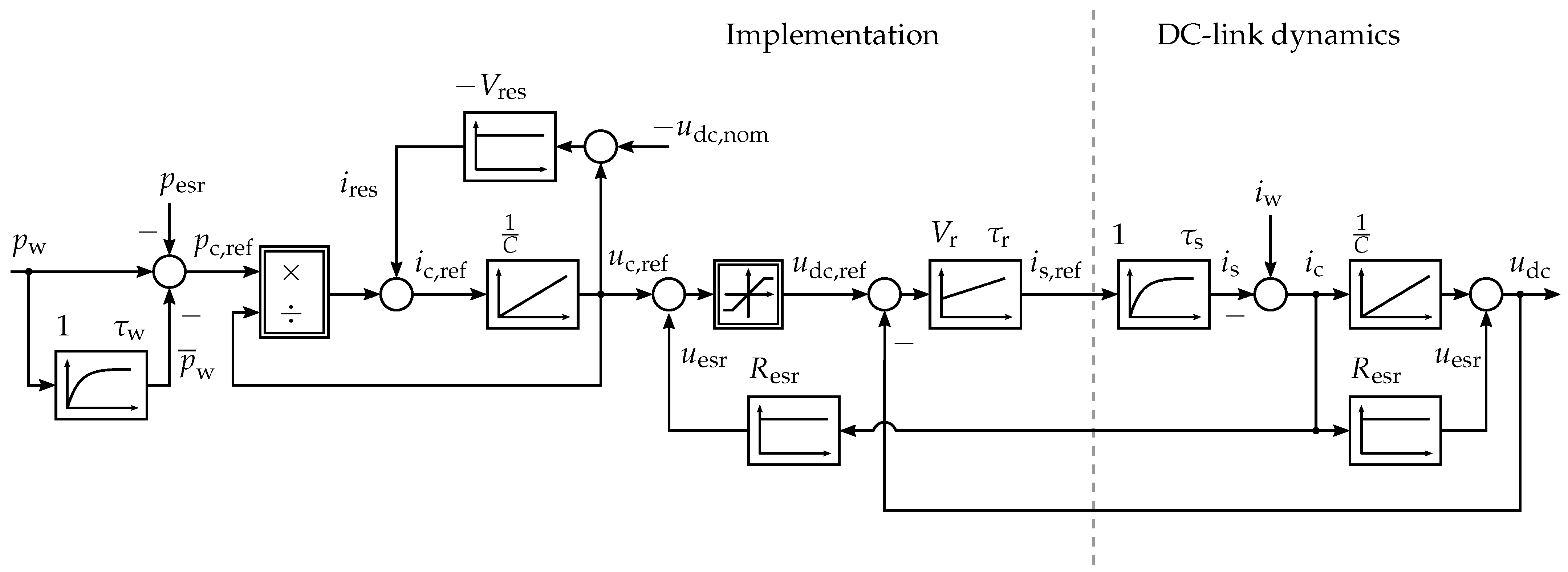
In Figure 6, the block diagram of the whole control system is shown. The restoring current is added to the reference current before the integrator, which leads to an integrating, as well as a filtering behaviour of this restoring term. The crossover frequency of the transfer function
is given by
which yields the proportional gain . The crossover frequency is set to one-tenth of the lowest frequency of the waves, which can occur, which is approximately .
Finally, the resulting voltage is limited to the desired operating range. This ensures, that the DC-link voltage does not exceed the limits, even if more energy needs to be stored due to very high power peaks. The fast voltage control loop guarantees, that this excess energy is fed directly into the batteries. The alternative would be to have it dissipated by the braking chopper, which should be avoided, as it would lead to efficiency loss.
4. Stability Analysis
To prove the stability of the nonlinear control system with multiple feedback, a stability analysis is conducted in the state space. The nonlinear dynamics of the system are given by
where the state is introduced to represent the integral action of the PI-controller. The saturation is defined by
For the system to be analysed for stability, it must be linearised around the operation point. Since the operational DC-link voltage lies between the limits and , the saturation can be neglected, yielding
Notice, that and do not appear in (20), as they are compensated for by feedforward control. Only the dissipated power remains in the dynamic of , which must be subtracted from the incoming power of the WEC, as it is dissipated at the equivalent series resistor and cannot be used.
Furthermore, the expressions of the powers in (18) are replaced by the multiplication of their corresponding current and voltage. It is assumed that the averaged DC-link voltage and the operation point are constant and correspond to its nominal value , which is reasonable as the DC-link voltage changes little compared to the current from the WEC, as it can be seen from the results. The nonlinear dynamics of the reference voltage and the averaged input current are then given as follows
Linearization around the operation point yields the small signal state space representation of the DC-link control system as follows
with the coefficient
A Linear Time-Invariant (LTI) system is exponentially stable if and only if its characteristic polynomial a Hurwitz polynomial, which here is given as
with
The term can be factored out. It is stable for all and therefore does not have to be considered for the stability analysis, which reduces the order of the polynomial to four. According to the Hurwitz criterion, the system is stable if ([44] Section 5.4.2)
- (i)
- all coefficients are positive (i.e., for ) and
- (ii)
- all leading principal minors of the Hurwitz matrix are positive.
Due to the redundancy of the Hurwitz criterion and according to the Liénard-Chipart criterion, for a fourth-order polynomial, it is sufficient to evaluate only the leading principal minors
for positivity in addition to the coefficients ([46] Section 3.4.5).
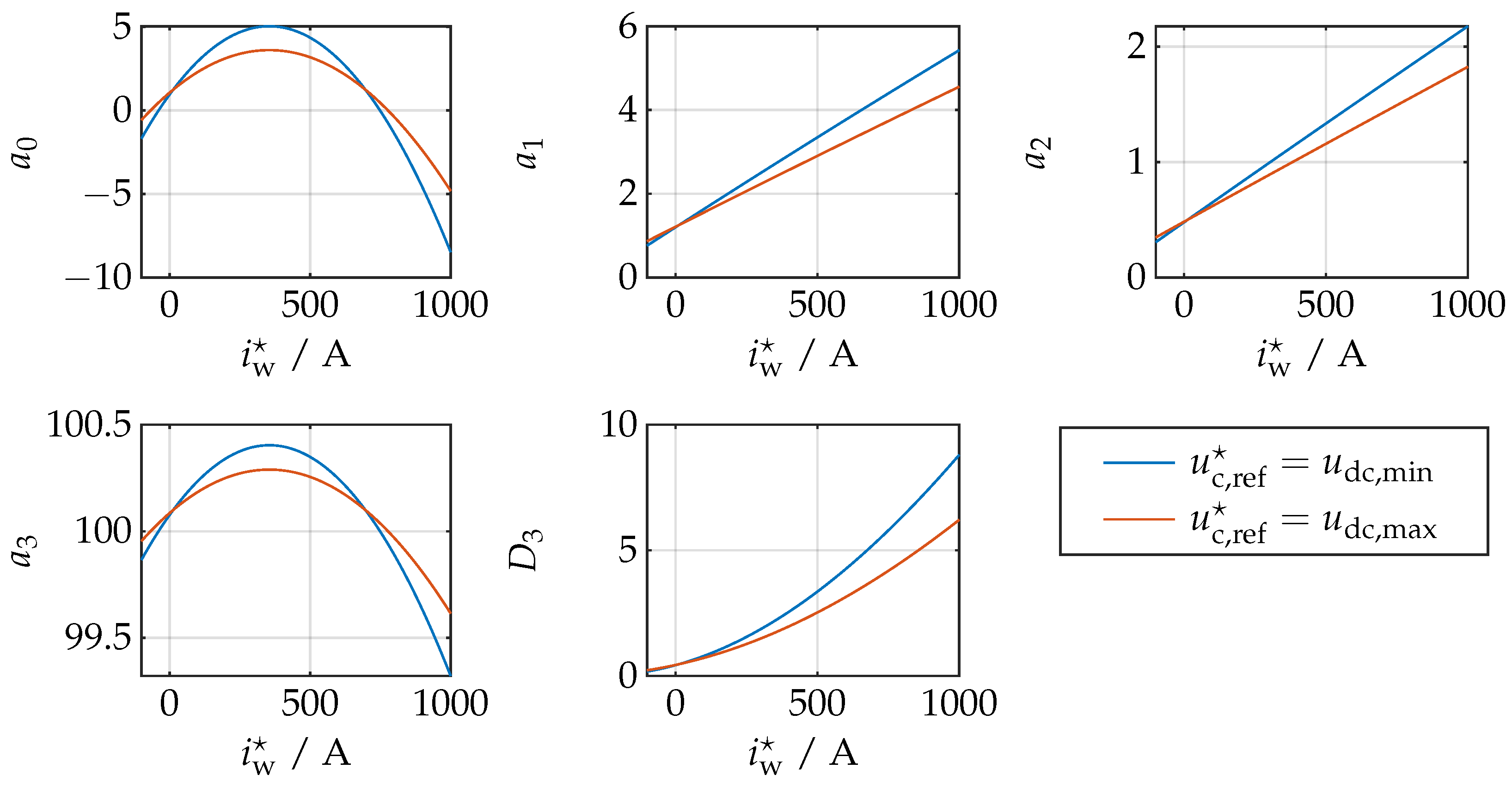
The determinate also leads to a fourth-order polynomial in the arguments , and (due to squaring of ), which is why a numerical approach is chosen to prove the positivity for various operation points. Therefore, the physical constraints are included and used accordingly to account for the worst-case. Figure 7 shows the coefficients to and the determinant over the input operational current and for two different reference voltages and . Further analysis shows, that the worst-case of stability is if the reference voltage is set to the minimum DC-link voltage , the current flowing into the DC/DC converter is set to and the current is set to zero, which is shown by the blue curves in Figure 7.
Each value is positive at least in the range . Physically, it is impossible for these limits to be exceeded, which is why the analysed system is exponentially stable.
5. Results
In this section, the results of the DC-link control are presented, where the measured quantities under typical sea conditions are compared to the simulated ones. The measured current and power of the generator units are used as inputs for the simulation.
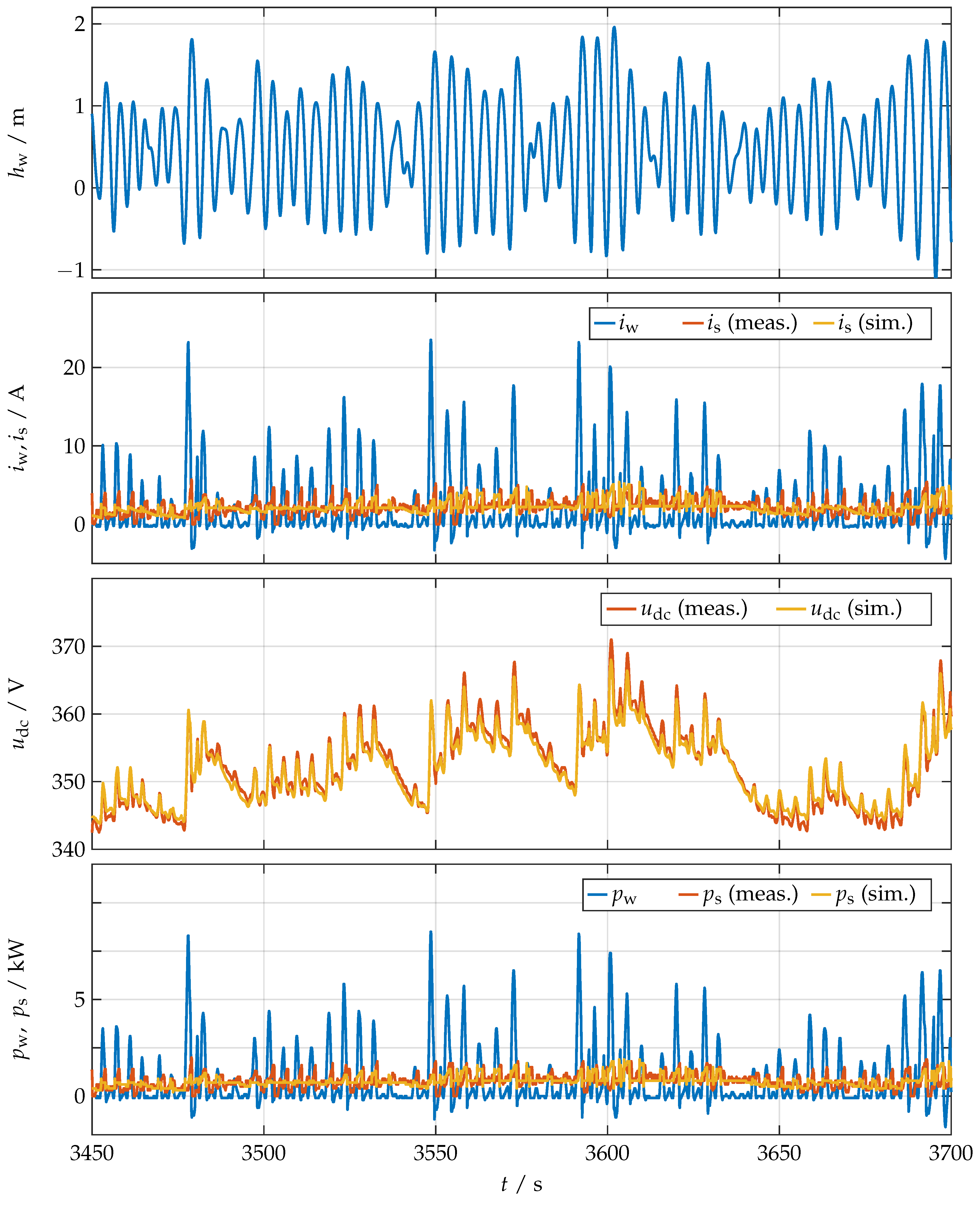
Figure 8 shows the results, beginning with the relative rod position at the top, to illustrate the movement of the point absorber. A laser sensor, mounted on the WEC structure, measures the distance to a reflector on the lifting rod. The analogue signal from the sensor is connected to the PLC, which converts and records all data. The next subplot shows the currents, where the blue line is the measured current , coming from the generator units. The red line is the measured current and the yellow line is the simulated current . The currents are measured indirectly via shunt resistors. The voltage over the shunt resistor is connected via an operational amplifier circuit to the PLC.
In the third subplot, the DC-link voltage is shown, where, as before, the red signal is the measured voltage and the yellow signal is the simulated voltage. The voltage is also measured and fed to the PLC via an operational amplifier circuit. At the bottom, the power of the generator units and the resulting smoothed power from the measurement and the simulation are shown.
The measurement was made, when the generated power was very high and the significant wave period with about was very short, as this is the most challenging condition for power smoothing. The peaks in the current from the generator units occur when the rod is moving upwards. This is where the most power is produced, as seen in the last subplot. The shapes of the currents and the corresponding powers are very similar. This is due to the high capacitance, so the change in the DC voltage does not significantly affect the power. Thus, the power is mainly determined by the current. The measured, smoothed power fluctuates slightly more than the simulated one. This is mainly caused by parameter uncertainties and noise.
The DC-link voltage , shown in the third subplot can be reproduced very well by the simulation. The average voltage is about the aimed , which is achieved by the restoring component , defined in Equation (15). The DC-link voltage can be used to determine the power generated. Each wave causes a high current flow into the supercapacitor bank, resulting in a voltage peak, induced by the ESR of the capacitors. Therefore, its modelling is especially important to calculate the reference voltage correctly. Disregarding these voltage peaks, there are grouped time intervals where more energy is generated than in others. This results from the tendency for larger waves to be grouped together, which is called wave groupiness ([1] Section 3.3.4), [47]. This can also be concluded from the movement of the lifting rod. Thus, power smoothing must not only smooth the power between two waves but also over these sets of waves for a longer period of time.
The resulting power into the energy storage system is well smoothed, also over multiple sets of waves, as seen in the last subplot. This confirms that both the system parameters and the designed controller were chosen correctly and are working very well. Thus, the extended lifetime of the batteries can be guaranteed. Furthermore, the simulation can reproduce the measured quantities very well, which validates the used model and allows further development of the system.
6. Conclusions
The electrical system of a wave energy converter prototype was presented. To smooth the highly fluctuating power, generated by the waves’ movements, a supercapacitor bank was directly connected to the DC-link. A unidirectional DC/DC converter was used to charge batteries from the DC-link.
To charge and discharge the supercapacitor bank during the period of a wave, the DC-link voltage must change, according to the fluctuating power. The DC-link voltage is controlled by the current through the DC/DC converter, where the reference current is computed in a PLC and transmitted to the converter. The control system is divided into two parts. The first part measures the generated power and calculates the reference DC-link voltage, yielding a nonlinear control system. The subsequent voltage control loop ensures that the DC-link voltage follows this reference. To prove a safe and stable operation, a stability analysis was conducted. The nonlinear dynamics were linearised around the operational point, yielding the small signal state space representation of the DC-link control system. Numerical analysis showed that the analysed system is exponentially stable.
The presented results in Section 5 show a nicely smoothed power. Under the given wave conditions, even the power fluctuation resulting from wave groupiness can be smoothed over multiple wave groups and a longer period of time, which indicates a proper system and controller design. The simulation results match the measurement results, on the bases of which further development can be initiated. As next steps, a bidirectional DC/DC converter shall be installed to connect the supercapacitor bank to the DC-link. This allows a more constant voltage in the DC-link, which is better for the control of the generator units and reduces the transmission losses. In addition, supercapacitors can be utilized more efficiently.
Author Contributions
Conceptualization, S.K. and C.M.H.; methodology, S.K. and C.M.H.; software, S.K.; validation, S.K. and C.M.H.; formal analysis, S.K. and C.M.H.; investigation, S.K.; resources, S.K. and C.M.H.; data curation, S.K.; writing—original draft preparation, S.K.; writing—review and editing, S.K. and C.M.H.; visualization, S.K.; supervision, C.M.H.; project administration, S.K. All authors have read and agreed to the published version of the manuscript.
Funding
This research received no external funding.
Institutional Review Board Statement
Not applicable.
Informed Consent Statement
Not applicable.
Data Availability Statement
Not applicable.
Conflicts of Interest
The authors declare no conflict of interest.
Nomenclature
| natural and real numbers | |
| column vector, (where means “is defined as” and means “transposed”) | |
| Eucilidean norm of | |
| real matrix with n rows and m columns, n, | |
| zero matrix | |
| identity matrix | |
| reference value of e.g., voltage, current and power | |
| nominal value of e.g., voltage, current and power | |
| maximum value of e.g., voltage, current and power | |
| minimum value of e.g., voltage, current and power | |
| average value of e.g., voltage, current and power | |
| DC-link voltage | |
| battery voltage and current | |
| current and power from the generator units | |
| current and power flowing into the DC/DC converter | |
| quantity, representing the integral action of the PI-controller | |
| C | capacitance of the supercapacitor bank |
| equivalent series resistors (ESR) of the supercapacitor bank | |
| voltage and current of the capacitance | |
| voltage and power of the ESR | |
| stored energy in the supercapacitor bank | |
| time constant of the current dynamics of the DC/DC converter | |
| time constant of the low pass filter to filter | |
| parameter of the PI-controller | |
| restoring current, factor and frequency | |
| quantity vector of the operation point |
References
- Pecher, A.; Kofoed, J. Handbook of Ocean Wave Energy; Springer: Cham, Switzerland, 2017. [Google Scholar] [CrossRef] [Green Version]
- Kempener, R.; Neumann, F. Ocean Energy Technology Brief; Technical Report; IRENA—International Renewable Energy Agency: Abu Dhabi, United Arab Emirates, 2014. [Google Scholar]
- Mørk, G.; Barstow, S.; Kabuth, A.; Teresa Pontes, M. Assessing the Global Wave Energy Potential. In Proceedings of the 29th International Conference on Ocean, Offshore Mechanics and Arctic, Shanghai, China, 6–11 June 2010; Volume 3. [Google Scholar] [CrossRef]
- Reguero, B.G.; Losada, I.J.; Méndez, F.J. A global wave power resource and its seasonal, interannual and long-term variability. Appl. Energy 2015, 148, 366–380. [Google Scholar] [CrossRef]
- Fairley, I.; Lewis, M.; Robertson, B.; Hemer, M.; Masters, I.; Horrillo-Caraballo, J.; Karunarathna, H.; Reeve, D.E. A classification system for global wave energy resources based on multivariate clustering. Appl. Energy 2020, 262, 114515. [Google Scholar] [CrossRef]
- Yetkin, M.; Kalidoss, S.; Curtis, F.E.; Snyder, L.V.; Banerjee, A. Practical optimal control of a wave-energy converter in regular wave environments. Renew. Energy 2021, 171, 1382–1394. [Google Scholar] [CrossRef]
- Rahm, M.; Svensson, O.; Bostrom, C.; Waters, R.; Leijon, M. Experimental results from the operation of aggregated wave energy converters. IET Renew. Power Gener. 2012, 6, 149–160. [Google Scholar] [CrossRef] [Green Version]
- Sjolte, J.; Tjensvoll, G.; Molinas, M. Power Collection from Wave Energy Farms. Appl. Sci. 2013, 3, 420–436. [Google Scholar] [CrossRef]
- Bailey, H.; Robertson, B.; Ortiz, J.; Buckham, B. Stochastic Methods to Predict WEC Array Power for Grid Integration. In Proceedings of the 11th European Wave and Tidal Energy Conference, Nantes, France, 6–11 September 2015. [Google Scholar]
- Göteman, M.; Engström, J.; Eriksson, M.; Isberg, J.; Leijon, M. Methods of reducing power fluctuations in wave energy parks. J. Renew. Sustain. Energy 2014, 6, 043103. [Google Scholar] [CrossRef] [Green Version]
- Astariz, S.; Iglesias, G. Output power smoothing and reduced downtime period by combined wind and wave energy farms. Energy 2016, 97, 69–81. [Google Scholar] [CrossRef]
- Veigas, M.; Iglesias, G. A Hybrid Wave-Wind Offshore Farm for an Island. Int. J. Green Energy 2015, 12, 570–576. [Google Scholar] [CrossRef]
- Gao, Q.; Ding, B.; Ertugrul, N.; Li, Y. Impacts of mechanical energy storage on power generation in wave energy converters for future integration with offshore wind turbine. Ocean Eng. 2022, 261, 112136. [Google Scholar] [CrossRef]
- Santos, M.; Salcedo, F.; Haim, D.B.; Mendia, J.L.; Ricci, P.; Villate, J.; Khan, J.; Leon, D.; Arabi, S.; Moshref, A.; et al. Integrating Wave and Tidal Current Power: Case Studies through Modelling and Simulation; Research Report Document No: T0331; International Energy Agency Implementing Agreement on Ocean Energy Systems: Paris, France, 2011. [Google Scholar]
- Blavette, A.; O’Sullivan, D.L.; Lewis, A.W.; Egan, M.G. Impact of a wave farm on its local grid: Voltage limits, flicker level and power fluctuations. In Proceedings of the 2012 Oceans-Yeosu, Yeosu, Korea, 21–24 May 2012; pp. 1–9. [Google Scholar] [CrossRef] [Green Version]
- Murray, D.B.; Egan, M.G.; Hayes, J.G.; O’Sullivan, D.L. Applications of Supercapacitor Energy Storage for a Wave Energy Converter System. In Proceedings of the 8th European Wave and Tidal Energy Conference, Uppsala, Sweden, 7–11 September 2009. [Google Scholar]
- Barelli, L.; Bidini, G.; Ciupageanu, D.; Ottaviano, A.; Pelosi, D.; Gallorini, F.; Alessandri, G.; Atcheson Cruz, M. An effective solution to boost generation from waves: Benefits of a hybrid energy storage system integration to wave energy converter in grid-connected systems. Open Res. Eur. 2022, 2, 40. [Google Scholar] [CrossRef]
- Glavin, M.E.; Chan, P.K.W.; Armstrong, S.; Hurley, W.G. A stand-alone photovoltaic supercapacitor battery hybrid energy storage system. In Proceedings of the 2008 13th International Power Electronics and Motion Control Conference, Poznan, Poland, 1–3 September 2008; pp. 1688–1695. [Google Scholar] [CrossRef]
- Burke, A. Ultracapacitors: Why, how, and where is the technology. J. Power Sources 2000, 91, 37–50. [Google Scholar] [CrossRef] [Green Version]
- Lijun Gao, R.A.D.; Liu, S. Power Enhancement of an Actively Controlled Battery/Ultracapacitor Hybrid. IEEE Trans. Power Electron. 2005, 20, 236–243. [Google Scholar] [CrossRef]
- Abbey, C.; Joos, G. Supercapacitor Energy Storage for Wind Energy Applications. IEEE Trans. Ind. Appl. 2007, 43, 769–776. [Google Scholar] [CrossRef]
- Li, W.; Joos, G.; Abbey, C. A Parallel Bidirectional DC/DC Converter Topology for Energy Storage Systems in Wind Applications. In Proceedings of the 2007 IEEE Industry Applications Annual Meeting, New Orleans, LA, USA, 23–27 September 2007; pp. 179–185. [Google Scholar] [CrossRef]
- Falcão, A.O. Control of an oscillating-water-column wave power plant for maximum energy production. Appl. Ocean Res. 2002, 24, 73–82. [Google Scholar] [CrossRef]
- Yoshida, T.; Sanada, M.; Morimoto, S.; Inoue, Y. Study of Flywheel Energy Storage System for Power Leveling of Wave Power Generation System. In Proceedings of the 2012 15th International Conference on Electrical Machines and Systems (ICEMS), Sapporo, Japan, 21–24 October 2012; pp. 1–5. [Google Scholar]
- Nie, Z.; Xiao, X.; Kang, Q.; Aggarwal, R.; Zhang, H.; Yuan, W. SMES-Battery Energy Storage System for Conditioning Outputs From Direct Drive Linear Wave Energy Converters. IEEE Trans. Appl. Supercond. 2013, 23, 5000705. [Google Scholar] [CrossRef]
- Zhou, Z.; Benbouzid, M.; Charpentier, J.F.; Scuiller, F.; Tang, T. A review of energy storage technologies for marine current energy systems. Renew. Sustain. Energy Rev. 2013, 18, 390–400. [Google Scholar] [CrossRef] [Green Version]
- Aubry, J.; Bydlowski, P.; Multon, B.; BEN AHMED, H.; Borgarino, B. Energy Storage System Sizing for Smoothing Power Generation of Direct Wave Energy Converters. In Proceedings of the 3rd International Conference on Ocean Energy, Bilbao, Spain, 6 October 2010; ISBN 978-84-693-5467-4. [Google Scholar]
- Moreno-Torres, P.; Blanco, M.; Navarro, G.; Lafoz, M. Power Smoothing System for Wave Energy Converters by means of a Supercapacitor-Based Energy Storage System. In Proceedings of the 17th European Conference on Power Electronics and Applications (EPE’15 ECCE-Europe), Geneva, Switzerland, 8–10 September 2015; pp. 1–9. [Google Scholar] [CrossRef]
- Nie, Z.; Xiao, X.; Hiralal, P.; Huang, X.; McMahon, R.; Zhang, M.; Yuan, W. Designing and Testing Composite Energy Storage Systems for Regulating the Outputs of Linear Wave Energy Converters. Energies 2017, 10, 114. [Google Scholar] [CrossRef] [Green Version]
- Rajapakse, G.; Jayasinghe, S.; Fleming, A.; Negnevitsky, M. Grid Integration and Power Smoothing of an Oscillating Water Column Wave Energy Converter. Energies 2018, 11, 1871. [Google Scholar] [CrossRef] [Green Version]
- Navarro, G.; Blanco, M.; Torres, J.; Nájera, J.; Santiago, A.; Santos-Herran, M.; Ramírez, D.; Lafoz, M. Dimensioning Methodology of an Energy Storage System Based on Supercapacitors for Grid Code Compliance of a Wave Power Plant. Energies 2021, 14, 985. [Google Scholar] [CrossRef]
- Masuda, A.; Goto, H. Control Strategy for Power Smoothing Converter with Energy Storage for Maximum Power Controlled Wave Energy Converter. In Proceedings of the 2021 10th International Conference on Renewable Energy Research and Application (ICRERA), Ankara, Turkey, 26–29 September 2021; pp. 235–238. [Google Scholar] [CrossRef]
- Krüner, S.; Hackl, C.M. Experimental Identification of the Optimal Current Vectors for a Permanent-Magnet Synchronous Machine in Wave Energy Converters. Energies 2019, 12, 862. [Google Scholar] [CrossRef] [Green Version]
- Maxwell Technologies. BC Series Ultracapacitors-BCAP0350. Datasheet. Available online: https://maxwell.com/products/ultracapacitors/cells/ (accessed on 18 October 2022).
- Linzen, D.; Buller, S.; Karden, E.; De Doncker, R.W. Analysis and Evaluation of Charge-Balancing Circuits on Performance, Reliability, and Lifetime of Supercapacitor Systems. IEEE Trans. Ind. Appl. 2005, 41, 1135–1141. [Google Scholar] [CrossRef]
- Diab, Y.; Venet, P.; Rojat, G. Comparison of the Different Circuits Used for Balancing the Voltage of Supercapacitors: Studying Performance and Lifetime of Supercapacitors. ESSCAP; HAL: Lausanne, Switzerland, 2006. [Google Scholar]
- Shi, L.; Crow, M.L. Comparison of Ultracapacitor Electric Circuit Models. In Proceedings of the 2008 IEEE Power and Energy Society General Meeting—Conversion and Delivery of Electrical Energy in the 21st Century, Pittsburgh, PA, USA, 20–24 July 2008; pp. 1–6. [Google Scholar] [CrossRef]
- Fletcher, S.; Kirkpatrick, I.; Dring, R.; Puttock, R.; Thring, R.; Howroyd, S. The modelling of carbon-based supercapacitors: Distributions of time constants and Pascal Equivalent Circuits. J. Power Sources 2017, 345, 247–253. [Google Scholar] [CrossRef]
- Daratha, N.; Polinder, H.; de Sousa Prado, M. A first-order energy storage requirements estimation for an Archimedes Wave Swing Park. In Proceedings of the 2008 IEEE International Conference on Sustainable Energy Technologies, Singapore, 24–27 November 2008; pp. 1161–1165. [Google Scholar] [CrossRef]
- Wu, E.; Knight, A.M. Considerations for sizing energy storage technologies in wave energy systems. In Proceedings of the 2017 20th International Conference on Electrical Machines and Systems (ICEMS), Sydney, Australia, 11–14 August 2017; pp. 1–6. [Google Scholar] [CrossRef]
- Di Domenico, F.; Steiner, A.; Catly, J. Design of a 600 W HB LLC Conver ter Using 600 V CoolMOSTM P6; Technical Report; Infinion: Singapore, 2015. [Google Scholar]
- Studer Innotec. VarioString VS-70. Datasheet. Available online: https://www.studer-innotec.com/de/produkt-details/variostring-reihe/vs-70-313 (accessed on 18 October 2022).
- IEEE Std 1561-2019 (Revision of IEEE Std 1561-2007); IEEE Guide for Optimizing the Performance and Life of Lead-Acid Batteries in Remote Hybrid Power Systems. IEEE: New York, NY, USA, 2019; pp. 1–34. [CrossRef]
- Hackl, C.M. Non-identifier Based Adaptive Control in Mechatronics: Theory and Application; Springer International Publishing: Basel, Switzerland, 2017. [Google Scholar]
- Schröder, D.; Böcker, J. (Eds.) Elektrische Antriebe–Regelung von Antriebssystemen; Springer: Berlin/Heidelberg, Germany, 2020. [Google Scholar] [CrossRef]
- Ludyk, G. Theoretische Regelungstechnik 1; Springer: Berlin/Heidelberg, Germany, 1995. [Google Scholar]
- List, J.H. Wave groupiness variations in the nearshore. Coast. Eng. 1991, 15, 475–496. [Google Scholar] [CrossRef]
Figure 1.
Picture of the WEC prototype in Crete.

Figure 2.
Simplified schematic of the electrical system of the wave energy converter and illustration of the power flow, where is the fluctuating power from the WEC, is the power flowing in and out of the supercapacitors and is the smoothed power flow to the battery.
Figure 2.
Simplified schematic of the electrical system of the wave energy converter and illustration of the power flow, where is the fluctuating power from the WEC, is the power flowing in and out of the supercapacitors and is the smoothed power flow to the battery.

Figure 3.
CAD figure of the supercapacitor bank with a photograph of one supercapacitor module of the prototype.
Figure 3.
CAD figure of the supercapacitor bank with a photograph of one supercapacitor module of the prototype.

Figure 4.
Equivalent circuit of the supercapacitor bank.

Figure 5.
(a) Picture of the DC/DC converter VarioString VS-70 and (b) LLC resonant topology of the VarioString VS-70 DC/DC converter with a split resonant capacitor technique.
Figure 5.
(a) Picture of the DC/DC converter VarioString VS-70 and (b) LLC resonant topology of the VarioString VS-70 DC/DC converter with a split resonant capacitor technique.

Figure 6.
Block diagram of the voltage control loop for power smoothing.

Figure 7.
Numerical stability analysis of the coefficients to and the determinant over the input operational current and for two different reference voltages [![Sustainability 14 13708 i001]() ] and [
] and [![Sustainability 14 13708 i002]() ], where accounts for the worst-case.
], where accounts for the worst-case.
 ] and [
 ], where accounts for the worst-case.
Figure 7.
Numerical stability analysis of the coefficients to and the determinant over the input operational current and for two different reference voltages [![Sustainability 14 13708 i001]() ] and [
] and [![Sustainability 14 13708 i002]() ], where accounts for the worst-case.
], where accounts for the worst-case.
] and [], where accounts for the worst-case.
Figure 8.
Comparison of the measured [![Sustainability 14 13708 i002]() ] and simulated [
] and simulated [![Sustainability 14 13708 i003]() ] quantities of the DC-link control, with the rod position at the top, followed by the current and the smoothed current , the DC-link voltage and the power of the generator units and the smoothed power . The measured current and the power of the generator units are used as inputs for the simulation [
] quantities of the DC-link control, with the rod position at the top, followed by the current and the smoothed current , the DC-link voltage and the power of the generator units and the smoothed power . The measured current and the power of the generator units are used as inputs for the simulation [![Sustainability 14 13708 i001]() ].
].
] and simulated [ ] quantities of the DC-link control, with the rod position at the top, followed by the current and the smoothed current , the DC-link voltage and the power of the generator units and the smoothed power . The measured current and the power of the generator units are used as inputs for the simulation [].
Figure 8.
Comparison of the measured [![Sustainability 14 13708 i002]() ] and simulated [
] and simulated [![Sustainability 14 13708 i003]() ] quantities of the DC-link control, with the rod position at the top, followed by the current and the smoothed current , the DC-link voltage and the power of the generator units and the smoothed power . The measured current and the power of the generator units are used as inputs for the simulation [
] quantities of the DC-link control, with the rod position at the top, followed by the current and the smoothed current , the DC-link voltage and the power of the generator units and the smoothed power . The measured current and the power of the generator units are used as inputs for the simulation [![Sustainability 14 13708 i001]() ].
].
] and simulated [] quantities of the DC-link control, with the rod position at the top, followed by the current and the smoothed current , the DC-link voltage and the power of the generator units and the smoothed power . The measured current and the power of the generator units are used as inputs for the simulation [].

Table 1.
Eletrical parameters of the used supercapacitor cell, produced by Maxwell Technologies [34].
Table 1.
Eletrical parameters of the used supercapacitor cell, produced by Maxwell Technologies [34].
| Electrical Parameter | Symbol | Value |
|---|---|---|
| Rated Capacitance | ||
| Equivalent Series Resistor | ||
| Rated Voltage | ||
| Absolute Maximum Voltage | ||
| Absolute Maximum Current | ||
| Maximum Leakage Current |
Table 2.
Electrical parameters of a supercapacitor bank.
| Electrical Parameter | Symbol | Value |
|---|---|---|
| Rated Capacitance | C | |
| Equivalent Series Resistor | ||
| Rated Voltage | ||
| Absolute Maximum Voltage | ||
| Absolute Maximum Current |
Table 3.
Eletrical parameters of the VarioString VS-70 [42].
Table 3.
Eletrical parameters of the VarioString VS-70 [42].
| Electrical Parameter | Symbol | Value |
|---|---|---|
| Maximum Input Power | ||
| Maximum Input Voltage | ||
| Maximum Input Current | ||
| Nominal Battery Voltages | ||
| Maximum Battery Current | ||
| Maximum Efficiency | >98% |
Publisher’s Note: MDPI stays neutral with regard to jurisdictional claims in published maps and institutional affiliations. |
© 2022 by the authors. Licensee MDPI, Basel, Switzerland. This article is an open access article distributed under the terms and conditions of the Creative Commons Attribution (CC BY) license (https://creativecommons.org/licenses/by/4.0/).
Share and Cite
MDPI and ACS Style
Krüner, S.; Hackl, C.M. Nonlinear Modelling and Control of a Power Smoothing System for a Novel Wave Energy Converter Prototype. Sustainability 2022, 14, 13708. https://0-doi-org.brum.beds.ac.uk/10.3390/su142113708
AMA Style
Krüner S, Hackl CM. Nonlinear Modelling and Control of a Power Smoothing System for a Novel Wave Energy Converter Prototype. Sustainability. 2022; 14(21):13708. https://0-doi-org.brum.beds.ac.uk/10.3390/su142113708
Chicago/Turabian StyleKrüner, Simon, and Christoph M. Hackl. 2022. "Nonlinear Modelling and Control of a Power Smoothing System for a Novel Wave Energy Converter Prototype" Sustainability 14, no. 21: 13708. https://0-doi-org.brum.beds.ac.uk/10.3390/su142113708
Note that from the first issue of 2016, this journal uses article numbers instead of page numbers. See further details here.