1. Introduction
In many countries, including Poland, single-family houses are still the most popular type of residential buildings, and the demand for them further increased after the COVID-19 pandemic. According to the Central Statistical Office in Poland, in 2021 single-family houses accounted for 97.3% of all the buildings that were commissioned for use, with their number increasing by 17.8% when compared to the previous year. In total, 109,212 buildings were completed, including 106,261 single-family houses, with the average usable area of which being 133.3 m
2 [
1]. According to the International Energy Agency (IEA), buildings account for about 30% of used final energy and more than 55% of global electricity consumption. Energy use in the building sector has increased steadily since 2000 and has an annual average growth rate of around 1.1%. This is mainly driven by the fact that there has been an increase in floor area, which has grown by around 65% since 2000. Moreover, the rapidly growing demand for energy-consuming equipment and services in buildings in emerging economies has also contributed to this growth [
2].
The above data clearly prove that there is an ever-growing demand for individual forms of housing. At the same time, these data confirm the scale of the problem and the great need to look for alternative solutions that will reduce the negative impact of housing on the environment, especially in the case of single-family housing. Due to sustainable development goals (SDGs), radical action in the housing sector is needed on many levels. One of them is the search for innovative solutions and processes that allow for, e.g., a change in the consumption behavior of users, the reduction of energy consumption from non-renewable sources, the reduction of the demand for built-in and usable energy, and also the reduction of greenhouse gas emissions.
In Poland, steps are being taken to implement mechanisms in order to improve this difficult situation. To meet social expectations, the Polish government has introduced a special program that aims to simplify construction procedures for people who want to build a house with a small area [
3]. Therefore, from September 2021, a single-family detached building with a gross floor area of up to 70 m
2 and with no more than two stories can be built quickly—bypassing many burdensome formal procedures. This applies to houses with a usable area of up to 90–120 m
2 that are located on a plot with a minimum area of 500 m
2.
In addition, under the recast Energy Performance Building Directive (EPBD), efforts are also underway to improve the energy efficiency of buildings. In 2014, a three-stage phase of increasing the requirements for, among others, the parameters of the thermal insulation of building partitions, as well as reducing the index of the annual demand for non-renewable primary energy, was launched. This means that from 1 January 2021, single-family buildings must be designed in such a way as to achieve an EP index of no more than 70 kWh/(m
2y) for heating, ventilation, and hot water preparation [
4]. These provisions aim to implement nearly zero-energy buildings (NZEB) and plus-energy buildings (PEB), which can be achieved thanks to the use of, e.g., renewable energy sources (RES).
There is a deeply justified need to search for contemporary innovative solutions for single-family houses with respect to sustainability. A lot of research is being conducted in this direction, both around the world and in Poland. Bibliometric analysis of 2592 articles conducted by Bibal Manzoor and others (with the use of the Scopus database) showed that there are 252 publications in the field of the energy efficiency of buildings with regards to sustainability [
5]. An important role in this transformation is played by the change in the approach and mentality of architects regarding designing in the old formula and also their transition to an integrated design process [
6,
7,
8]. Moreover, the acceptance of the necessity to use renewable energy sources (RES) and the recognition of the opportunities they offer are also crucial. It is important to study the possibility of integrating photovoltaics (PV) with NZEB with regards to architecture [
9,
10]—especially building integrated photovoltaics (BIPV) systems [
11].
Plus energy buildings (PEBs) are the next step beyond the current EPBD requirements. However, they are not yet widely used and do not have a clear definition. They can be referred to as “buildings that produce more energy from renewable energy sources (RES) than they import over a year” [
12] or as “NZEBs that produce 30% or more of the required energy using on-site renewable energy” [
13]. Tuerk A. et al. reported that PEBs have the potential to be used in cities in plus energy districts (PEDs) [
14]. Research is being conducted concerning the operation of PV with battery energy storage systems (BESS) in urban residential buildings in various parts of the world [
15,
16]. There are studies related to PV systems and their energy potential in individual countries [
17]. Another category of research concerns life cycle assessment (LCA) and life cycle carbon footprint analyses, which show that PV systems in various forms have a carbon footprint similar to that of geothermal energy. This is worse than solar collectors, wind farms, and hydroelectric plants [
18].
Of particular importance are studies of the general possibilities of storing thermal energy in buildings [
19] and also the possibilities of using and storing solar energy in single-family buildings in the Polish climate. Bac A. et al. [
20] discussed ways of integrating the storage stack with the functional and spatial plan of a detached single-family house. From the point of view of energy efficiency, the best space for the location of the storage stack is inside the house. This is due to the fact that heat losses from the storage stack can be used for passive heating of the interior. Żabnieńska-Góra A. et al. [
21] analyzed photovoltaic and thermal systems. They came to the conclusion that, apart from cooperation with seasonal energy storage, such installations are not optimal in terms of energy during periods of lower insolation. Nemś et al. [
22,
23] studied the storage of sensible heat in a ceramic brick stack that used air as the working medium for heating a single-family house. They determined that with intelligent control of the airflow rate, the efficiency of such a storage system can be maximized. According to this analysis, heat storage in ceramic bricks was characterized by high efficiencies—ranging from 74% to 96% at an airflow rate of 0.0068 m
3/s. Several advantages of using ceramic bricks as a storage material were also highlighted, including their non-toxicity, affordability, and resistance to high temperatures.
Ocloń et al. [
24] described a system in which a set of photovoltaic thermal (PVT) hybrid solar panels and an evacuated solar collector with a water-to-water heat pump supplied heat to underground thermal storage tanks. This system provided domestic hot water and heating for a building in mountainous conditions in Poland. Yildiz et al. [
25] analyzed the amounts of PV energy that are used on average for heating domestic hot water. For this purpose, they created a unique dataset from 410 households and presented a comprehensive analysis of electricity and hot water consumption. On average, the excess generation of electricity from a 4.5 kW PV system was able to provide 48% of a household’s daily energy. Nordgård-Hansen E. et al. [
26] focused on detached residential houses in Norway, which were equipped with PV systems connected to electric batteries and optional ground-source heat pump systems for thermal energy storage. It was revealed that in the case of a variable electricity tariff, it is optimal to use seasonal thermal storage. It was also found that ground heat pumps contribute to greater heating stability, but they may not be economically beneficial for single-family houses. Pintanel M.T. et al. [
27] described a case study of a facility in Zaragoza (Spain), which had a photovoltaic and thermal hybrid solar field with a seasonal storage tank coupled to a water-to-water heat pump. The authors stated that this innovative heating system is a good solution for social housing. Its construction costs were found to be low, especially when subsidized by the state. Ghanem R.S. et al. [
28] analyzed a complex energy system for residential buildings in Amman (Jordan). The system was equipped with PV panels connected to electric batteries, a solid oxide fuel cell (SOFC) system that operated in a combined heat and power (CHP) mode, a solar thermal plant, and a thermal storage tank. Excess energy produced in the summer by the PV system was stored for later use (in winter) in a fuel warehouse. In terms of construction, the cost of SOFC-based micro-CHP systems has proven to be much higher than that of traditional technologies; however, they can be seen to provide energy self-sufficiency. Thinsurat K. et al. [
29] described a hybrid solar photovoltaic thermal collector that was integrated with a strontium chloride–ammonia thermo-chemical sorption storage system. The system under analysis was located in Newcastle upon Tyne in England. The energy analyses of the authors suggested that the use of hybrid solar photovoltaic thermal collectors (with an area of 26 m
2), which are integrated with a thermochemical sorption storage system, can fully meet the annual demand for hot water for an average single-person household. Moreover, they can cover at least half of the annual electricity consumption. Chwieduk B. and Chwieduk D. [
30] analyzed the utilization of energy for a PV system with a heat pump. The system was evaluated in the case of a low-energy house in the Polish climate during winter. The analyses were based on meteorological data for Warsaw. The authors showed that the reduction of primary energy consumption was not significant. However, to give a definite answer regarding the reduction of energy consumption, a study of the operation of the system over a whole year is required.
The authors of this article, in their previous publications, considered the use of a concentrating solar collector and a granite seasonal storage stack in order to provide heating for a single-family building [
20]. The obtained technical solution met the requirements regarding energy but strongly interfered with the architecture of the building. In addition, this solution did not meet the needs of residents in terms of electricity. Moreover, it did not create an energy-plus house. In the last few years, home PV installations have become very popular in Poland. They produce very useful electric energy, but not thermal energy, which is actually relatively more simple to produce. In addition, PV technologies are subject to systematic technological evolution, and every decade the efficiency of PV energy conversion increases by several percent when compared to previous years. It can therefore be expected that the use of PV technologies will continue to increase in the future. For this reason, the authors turned to the concept of using PV systems.
The issue of cooperation between PV panels and a thermal storage stack that is placed inside a single-family house is not recognized in the subject literature. The aim of this study is to propose an innovative concept of a plus-energy single-family house that was built in accordance with the latest legal regulations in Poland. The house is equipped with seasonal heat storage located in its residential space. Such a house will use solar energy and some form of seasonal heat storage, which will be analyzed later in the article.
2. Materials and Methods
2.1. The Concept of a Small Plus-Energy House
In the warm temperate climate that occurs in Poland, the basic problem of using solar energy for utility purposes is its small amount at the time that heating energy is needed. Therefore, storing the energy obtained in periods of very good availability of solar radiation is a challenge. Based on the aforementioned latest legal act concerning significant facilitations in the construction of houses in Poland, an “almost tiny house” was designed. This detached single-family house meets the requirements of sustainability thanks to the use of photovoltaics and a seasonal energy storage system and is in line with the idea of downsizing living spaces, simplifying such spaces, and essentially “living with less”. It combines minimal construction and operating costs and, at the same time, responds to the needs of modern residents. Thanks to the cooperation of the architect and engineers during the integrated design process (IDP), the house has been optimized in order to achieve the energy plus standard, i.e., it produces more energy than it consumes. The IDP was used at the very beginning of preparing the early sketch design, which gave an opportunity for obtaining synergy between the architecture and the energy system.
2.2. The Shape of the House and Its Technology
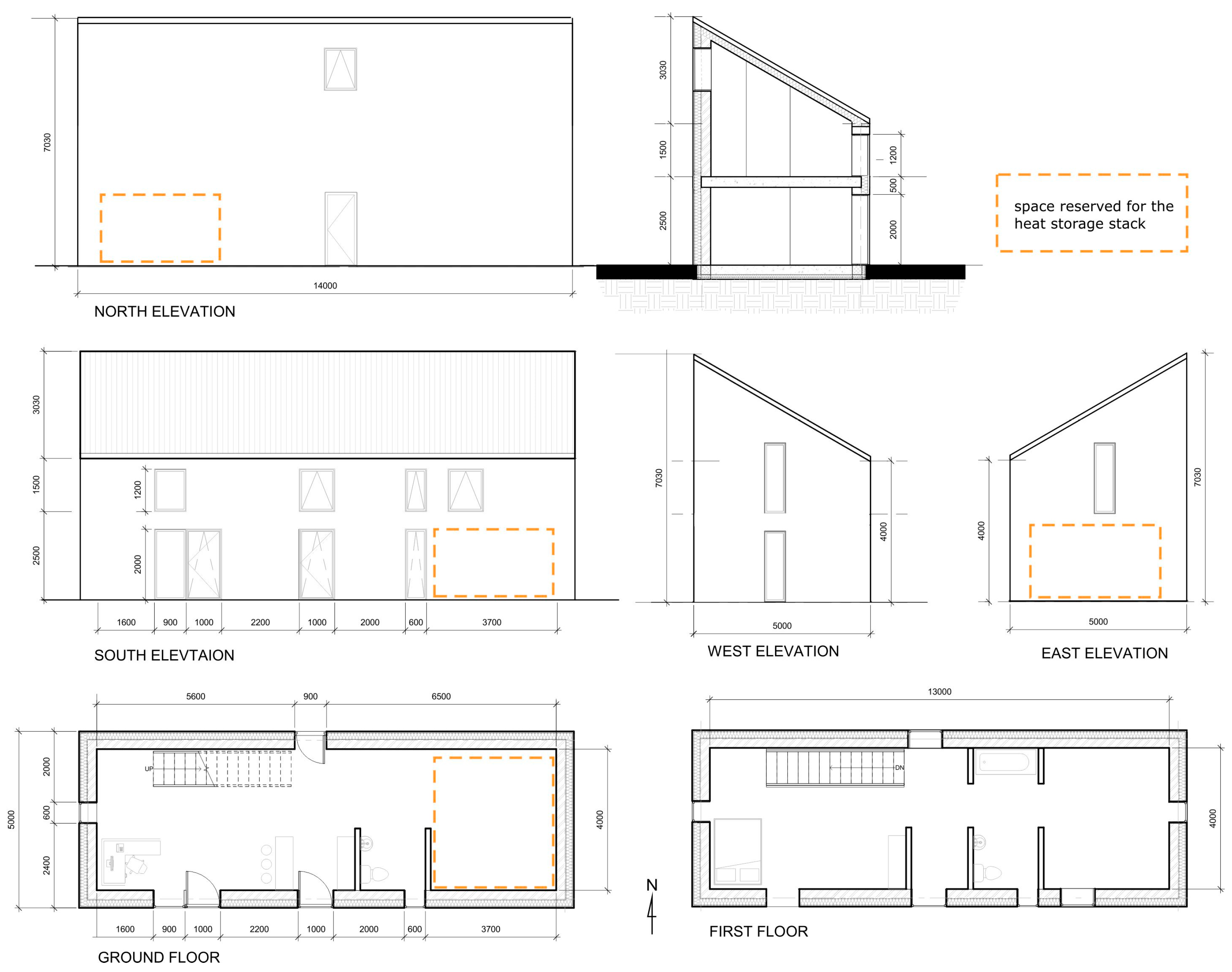
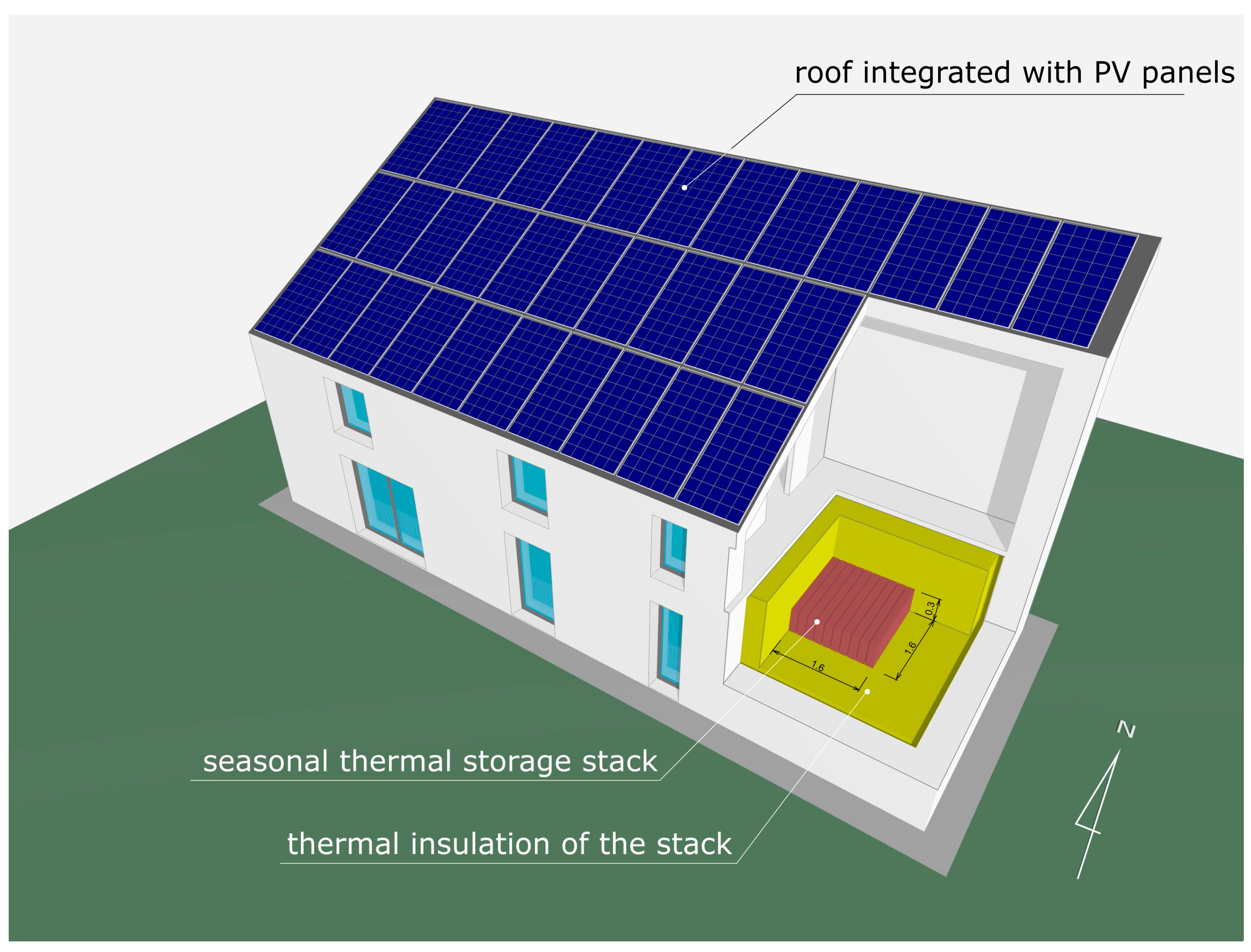
The house has external dimensions of 5.00 × 14.00 m (see
Figure 1). It is a two-story building with a shed roof, which is intended for full integration with photovoltaics. The total usable area of the ground floor and first floor is 98 m
2. This is a result of the gross floor area of the house, which is reduced by the building’s envelope and the surface of the internal partitions and stairs. The house is designed for comfortable living for a maximum of four residents. On the ground floor there is a common space, a living room, dining room, kitchen, and bathroom, and upstairs there is a space for individual use and a second bathroom.
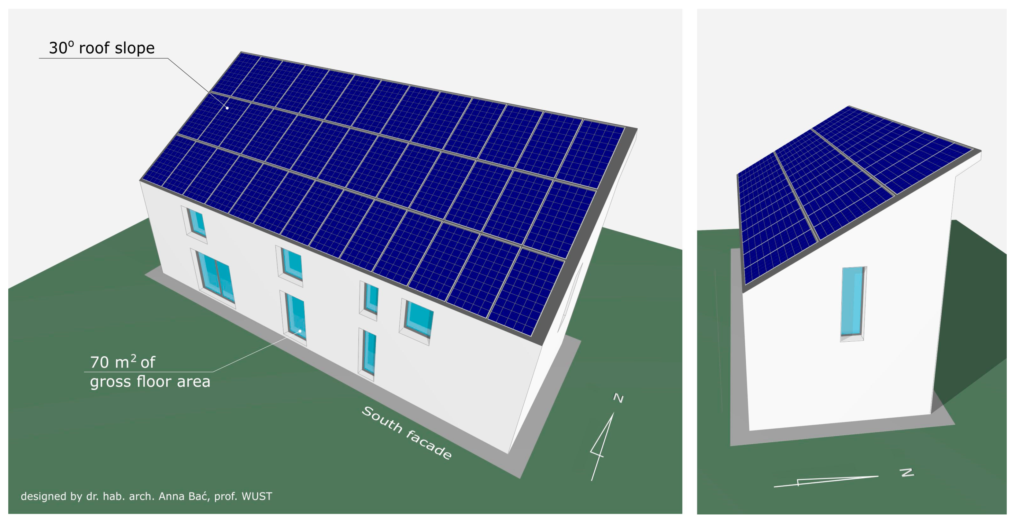
The elongated shape of the building (see
Figure 2) is meant to provide optimal space for both living and the assembly of PV panels on the roof. The minimalist area of the ground floor results from law restrictions. The extension of the first-floor area was abandoned in order to reduce the heated area and the volume of the building. The compact body is designed to reduce potential thermal bridges. The windows of the house face mainly south for the purpose of passive solar gains. For the same reason, there are small windows to the east and west and no windows to the north. The size of the windows has been optimized in terms of the required insolation and daylight illumination of 1/8 of the floor area.
The storage stack is located inside the building and constitutes the building’s integral part on the ground floor. The storage stack’s location is due to both its weight and the benefits of such an interior layout. During the heating season, heat losses through the thermal insulation of the storage stack are used to passively heat the rooms, and it can therefore be considered that waste heat is used. Access to the storage stack was provided from inside the house. Photovoltaic panels cover the entire roof area, which has southern exposure. An angle of inclination of 30° was adapted to enable the optimal use of solar radiation.
2.3. The Choice of Energy Storage Technology
There are currently many ways to store energy. Some of them are only suitable for industrial applications (hydrogen and flywheels), while others can be used for individual purposes (including single-family houses). In the case of mobile installations such as cars, planes, ships, and mobile phones, it is important to optimize energy storage technology with regard to the mass-energy stored (kJ/kg). Its value should be as high as possible. In the case of buildings, it is important to analyze the volumetric energy stored (MJ/m
3), which is due to the fact the installation should occupy as little living space as possible. Based on a review of the scientific literature and the authors’ own research,
Table 1 lists selected parameters of energy storage systems in the case of four technologies (sensible heat, latent heat (PCM), thermo-chemical, and an electric battery). Four basic parameters were analyzed:
Mass energy stored (kJ/kg),
Volumetric energy stored (MJ/m3),
Cost (USD/kJ),
Lifetime (years or cycles).
Table 1.
Selected features of energy storage technologies.
Table 1.
Selected features of energy storage technologies.
| Storage Technology | Storage Medium | Useful Temp.
Difference *
(°C) | Mass
Energy Stored (kJ/kg) | Volumetric
Energy Stored (MJ/m3) | Efficiency
of
Storage
(%) | Cost
(USD/kJ) | Lifetime (Years
or
Cycles) | Hazard |
|---|
Sensible
Heat | Water | 0–100 | 335.2 | 335.2 | | | | |
| Granite [31] | 450 | | 978 | | 0.000038 | 80 cycl. [32] | |
| Concrete [33,34] | 200 | 210 | 504 | | 0.00022 | | |
| Magnesite bricks [35] | 600 | 690 | 2 070 | | 0.00014 | | |
Latent
Heat
(PCM) | Paraffin wax [36] | 72–76 | 223 | 191 | | 0.047 | | |
| Erythritol [37,38] | 117 | 340 | 493 | | 0.01 | | |
| Palmitic acid [39,40] | 61 | 222 | 219 | | 0.28 | | |
| Adipic acid [41] | 152 | 275 | 374 | | 0.041 | | |
| CH3COONa3H2O [42] | 58 | 265 | | | 0.025 | | |
| Termochemical | Zeolite [43] | | 900 | 1980 | | 0.0006 | | |
Electric
battery ** | Lead–acid | | 180 | 360 | 80 | 0.024 | 8 years | fire |
| LiFePO4 | | 393 | 360 | | 0.096 | | fire |
| NiMH | | 277 | 650 | | 0.21 | | fire |
| Li-ion [44] | - | 720 | 800 | 95 | 0.092 | 40 years [45] | fire |
As shown in the table, the individual parameters vary greatly. In the case of sensible and latent heat storage technologies, the highest values of mass energy stored (690 kJ/kg) and volumetric energy stored (2070 MJ/m3) are achieved in the case of magnesite bricks. Thermochemical technology with zeolite also obtains similar parameters; however, it is several times more expensive than magnesite bricks. Batteries based on Li-ion technology also achieve favorable parameters (720 kJ/kg and 800 MJ/m3, respectively), but Li-ion technology is over 600 times(!) more expensive than magnesite bricks when it comes to construction costs. This technology also poses a significant fire hazard in the case of large installations and additionally, the production of batteries significantly burdens the environment. When considering energy (heat) storage in magnesite bricks, their additional advantage is the lack of emission of harmful or explosive gases, as well as their durability, which is estimated to be several dozen years of operation. The production of these bricks only affects the natural environment to a negligible extent. The high values of parameters calculated for magnesite bricks primarily result from the high density of this material and the very high temperature to which it can be heated. Due to it having so many advantages, it was decided to use this type of heat storage technology.
2.4. The Concept of the Energy System
Based on the experience and knowledge of the authors, and the conclusions resulting from the review of the latest publications, the elements of the energy system, which according to the authors should be used in the proposed system, were summarized. This system is proposed in order to meet the demands of space heating (without space cooling and domestic hot water usage) for the whole year. In order to properly understand the system, the main components are explained individually in the following paragraphs:
It was decided to use PV panels (although they are less efficient than a thermal solar collector) because they produce very useful electrical energy, and not thermal energy, which is relatively more simple to achieve. In addition, PV technology has become very popular in Poland in the last few years, and there is also a social demand for it. The system consists of a network of half-cut, p-type, monocrystalline cells of white composite foil, with anodized aluminum photovoltaic panels arranged serially on the South-end elevation of the roof of the building in order to generate electrical energy from solar radiation. The efficiency of these panels was tested to be around 20%, with the rated maximum power being 450 Wp/panel. Thirty-nine panels were used due to the fact that this number of panels provides the maximum coverage of the roof surface of the building.
The heater receives energy from the photovoltaic panels and converts it to thermal energy, which is then used to heat up the thermal storage stack.
This storage stack is an enlargement of an already-existing daily thermal energy storage device (described in the next chapter). The enlargement here applies to volume and weight, as well as its charging and discharging time.
The building was equipped with a foundation slab and thick thermal insulation placed under the slab, on the external walls, and on the roof of the building. Triple-pane windows were used, and there is a possibility of covering them with external blinds. The heat recovery system helps to recover waste heat from ventilation, as well as to maintain the quality of air. The heat recovery unit is powered by waste energy from the air leaving the building, and it is transferred in a counter-flow heat exchanger to the fresh air entering the building. Thanks to this, clean air is kept inside the living space. The counter-flow heat exchanger was chosen because of both its high efficiency and suitability for the building space.
The authors chose to call the innovative energy system described above a photovoltaic powered seasonal thermal storage system (PVPSTS). The intention of the authors is to analyze the energy possibilities of the proposed concept. For this purpose, a mathematical model was made and calculations were carried out, and the authors then attempted to evaluate the obtained results.
2.5. Thermal Storage with Air Heating
In Poland, electricity users can choose between tariffs marked as G11 and G12. The G11 tariff has a uniform cost of energy consumption around the clock. The G12 tariff has two prices: day, which is about 10% more expensive than G11, and night, which is about 50% cheaper than G12. The G12 tariff is cheaper at those times of the day when industry uses little electricity. Users can decide which tariff they want to use. The G11 tariff is intended for users who only use lighting and basic household technical equipment. In turn, the G12 tariff is intended for users who do not use gas heating, for those who heat their apartments or houses with electric dual-tariff air space heaters, and/or for those who heat (at night) domestic hot water in boilers with a large volume.
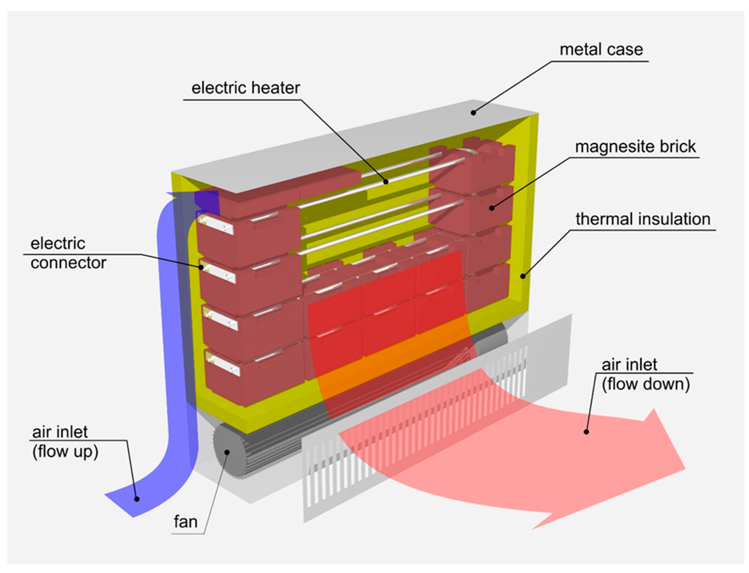
The electric dual-tariff heaters shown in
Figure 3 are relatively small (approx. 20 × 50 × 80 cm) and are filled with special shaped bricks made of magnesite ceramic that has a high density. Ceramic materials of this type are resistant to high temperatures and heat up to 600 °C (and even up to 650 °C in some solutions) in electric dual-tariff heaters. The heating process is carried out by a set of electric heaters placed between the bricks. These heaters are mainly powered at night by electricity that is charged at a cheaper night tariff. The heat storage in the bricks is used to heat the rooms with hot air for 24 h a day. Heat storage bricks are surrounded by a thin (about 3 cm) layer of thermal insulation, through which a certain amount of heat flux passively penetrates for 24 h a day. In addition, when more power for heating rooms is needed, a fan is activated in the heater. It forces cold air onto the bricks from below, which is then heated up by the bricks and blown out from the bottom of the heater into a room. The air inlet and outlet are located at the bottom of the heater in order to reduce the convective escape of hot air when the fan is not operating. The small size of heaters of this type allows for a daily period of heat storage.
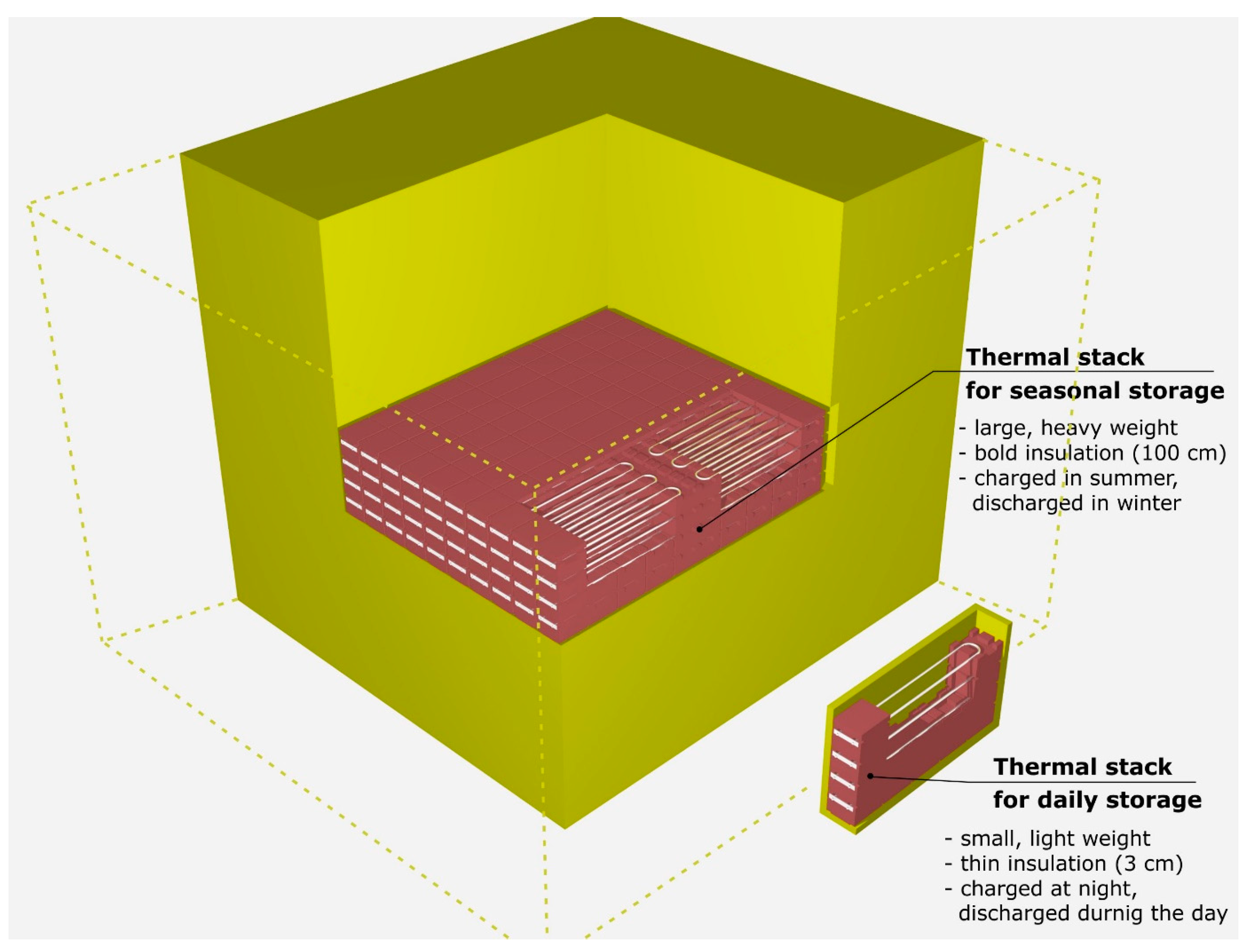
The technology of electric heaters with 24 h heat storage has been known for many years and is still used today in Poland. If there is a need to use heaters of this type, but with heat storage for periods of longer than one day, they should be enlarged. Based on the preliminary calculations that were carried out by the authors of this publication, the ceramic bed storage would have to be several dozen times larger. Ceramic blocks are arranged in a lattice structure with electric heaters running parallel through the blocks. However, it is not only the number of bricks and electric heaters that would have to be increased but also the thickness of the thermal insulation. It would be necessary to use approx. 100 cm of insulation, which is due to the intended long heat retention period. However, the maximum temperature of the bricks, and the way of receiving heat from the storage stack, would not change passive heat loss through the insulation and the active heat collection by the forcing of air between the bricks using a fan.
Figure 4 shows a storage stack that is suitable for the period of annual heat storage and which has a typical heater for daily heat storage.
2.6. The Proposed Innovative HVAC–PVPSTS System
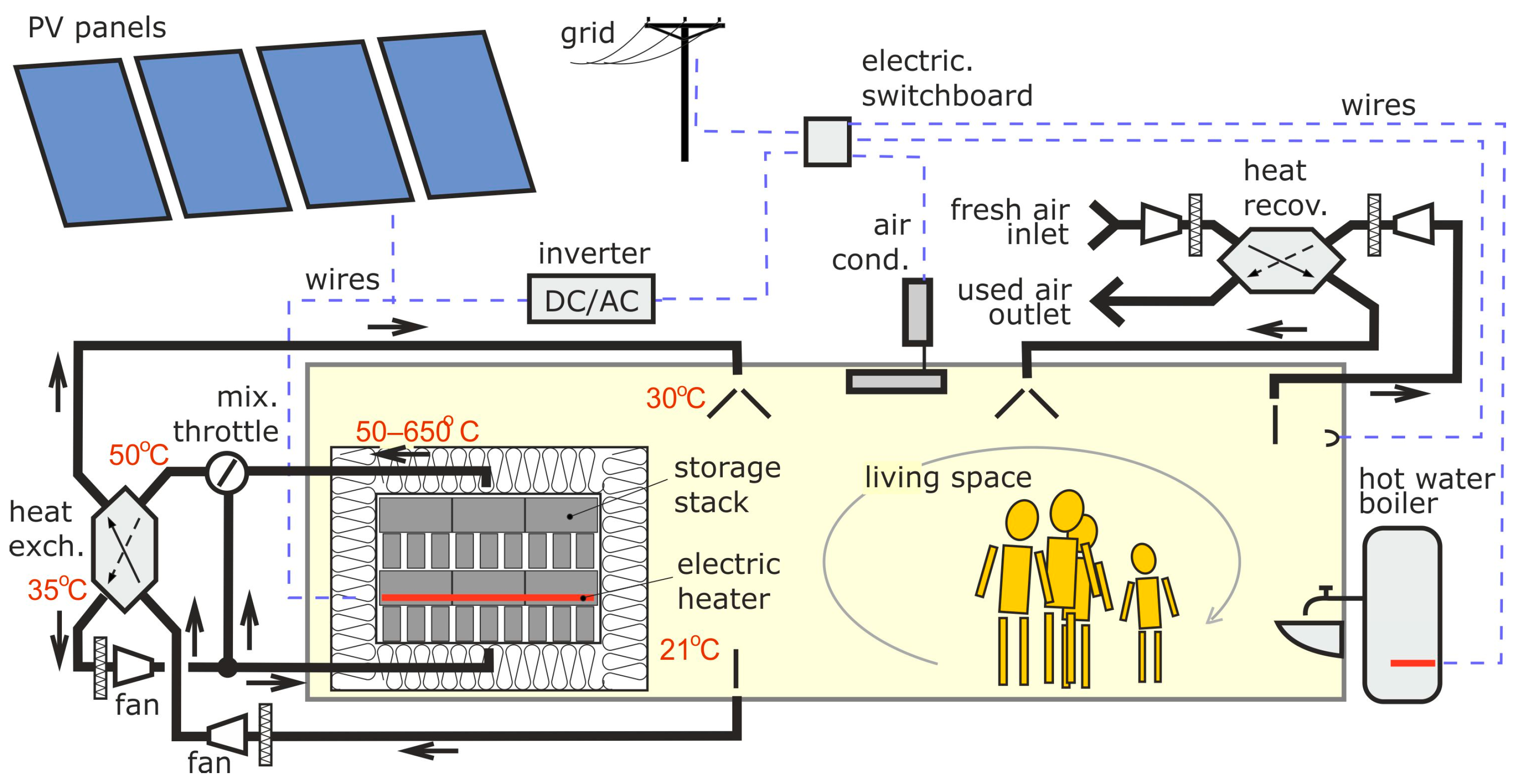
As illustrated in
Figure 5, the system receives solar energy through the south-facing photovoltaic panels installed on the roof of the building. These photovoltaic panels convert the received solar energy into electrical energy, which is then used to heat up the electric heaters running along the magnesite blocks. The electric heater heats up the blocks to a maximum of 600 °C.
The storage stack is located in the living space of the house in order to take advantage of the passive heat transfer (losses) through the thermal insulation of the stack. When there is a need to actively use the heat from the storage stack, the fan is used. However, the temperature of the storage stack during the year can vary from 50 to 600 °C, depending on the level it is charged to. To stabilize the operation of the heating system, hot air from the thermal storage system is sent to the mixing throttle valve (on the left in
Figure 5), where it then mixes with cold air. This automatically maintains a stable air temperature of 50 °C at the outlet of the mixing valve. This hot air (at a temperature of 50 °C) is ducted into a counter-flow heat exchanger, where it crosses the air that is leaving the living space. This meeting of fluids results in a further reduction in the temperature of this hot air to about 30 °C. The heat exchanger also functions as a dust separator in order to protect the storage stack from dust contamination from the living space. Such dust could be ignited by entering the high temperature area. The purified 30 °C air is then sent into the living space, while the cold air, along with the excess hot air separated by the mix throttle valve, is directed through a fan back into the thermal storage stack to restart the cyclical movement all over again. The air returning to the thermal storage stack is once again filtered in order to prevent the system from being contaminated with dust at such high temperatures.
An important element of PV systems is their cooperation with the grid system. In the adopted solution, in order to maintain the highest efficiency of energy conversion, the power supply for the storage stack heaters is located on the DC side of the electrical installation. The generated electricity is mainly intended for heating the thermal storage. If its temperature is already too high, or further heating of the thermal storage is not needed, then the generated electricity is exported via an inverter and an electric switchboard to the grid. On the grid side, the hot water production systems and the AC unit are also supplied. The energy balancing that was conducted for the purpose of the article was focused on the needs of heating the living space.
2.7. Mathematical Modelling of the System
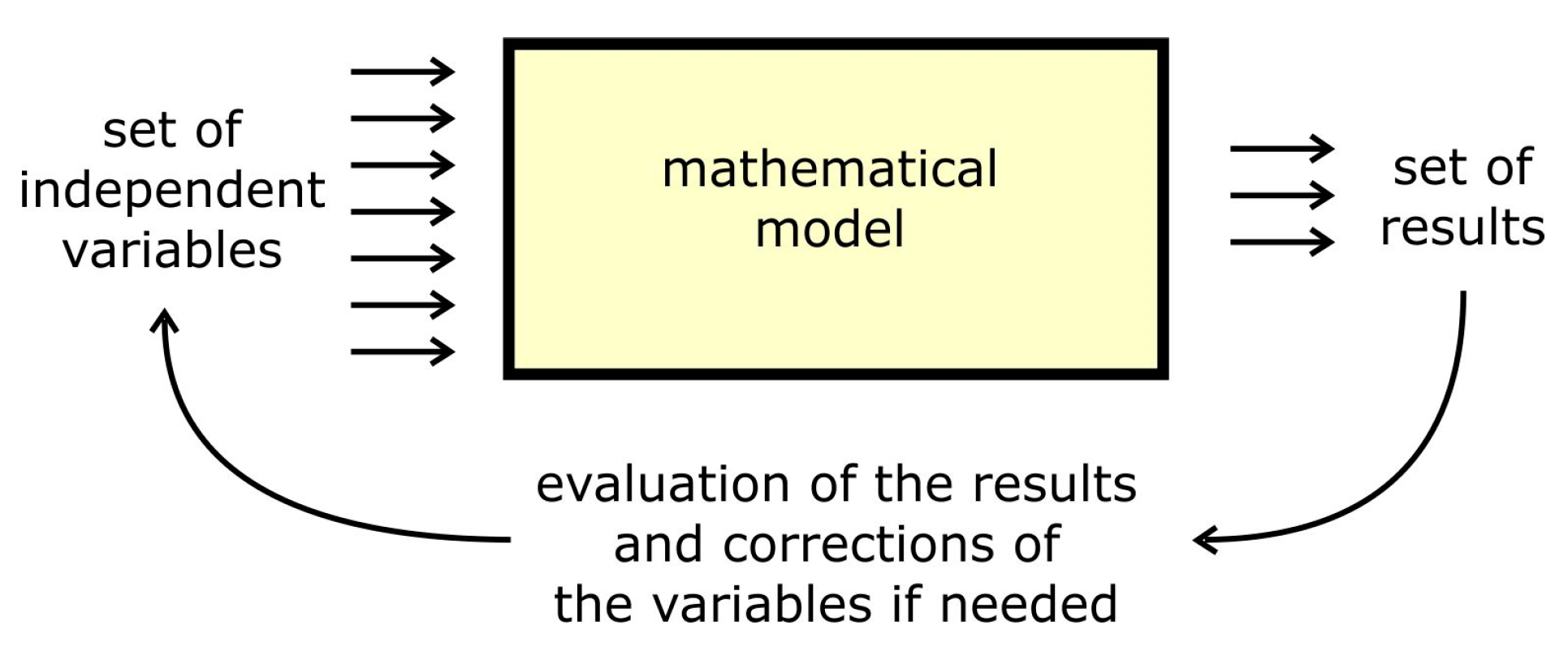
The “trial-and-error” method was used to find the required parameters of the energy system. According to E. G. Mbonipa et al. [
46], the method involves:
Selecting independent model parameters on the basis of previous knowledge and experience;
Adjusting parameter values and manually changing the model input files;
Running the model;
Evaluating the model and comparing it with observed data trends.
Repeating the last three steps until an acceptable calibration is achieved, or until the model performance criteria are met, is what actually forms the “trial-and-error” process of the method, as can be seen in
Figure 6.
In the presented case, several assumptions had to be made in order to facilitate the design of the system. One of them is the location of the building, which is related to the availability of typical meteorological year (TMY) data for selected locations in Poland. Other assumptions, including, among others, the technology and design of the building, the defining of the heating and cooling season, and the selection of the photovoltaic panel model, can be seen in
Table 2. The most important of the assumed data is the number of panels that is necessary to generate the electricity required for the entire year of the building’s operation, the size of the storage stack, and the choice of the day of starting the heating of the storage stack.
2.8. Energy Balance
The mathematical model was based on a detailed analysis of the heat exchange between the building’s elements, the environment, and the thermal storage stack. The calculations took into account:
Heat exchange through the walls with the ambient air;
Heat exchange through the roof with the ambient air;
Heat exchange through the floor with the heat from the ground under the building;
Heat exchange through the windows and doors with the ambient air;
Solar radiation coming through the windows with solar shading;
Loss of heat and air infiltration;
Loss of heat through intentional ventilation with heat recovery;
Heat gains from the residents;
Heat gains from working electrical devices;
Loss of heat from the ceramic storage stack through its insulation to the room.
The heat exchange through the walls, floor, and roof took into account both the thickness and the material of the building structure, as well as the applied layer of thermal insulation. In the case of solar radiation entering through the windows, it was assumed that they would not be covered during the winter in order to maximize the passive gains from radiation energy. In the summer, to reduce the consumption of cold air from the air-conditioning system, up to 25% of the surface of the windows was covered (when solar radiation exceeds 500 W/m2).
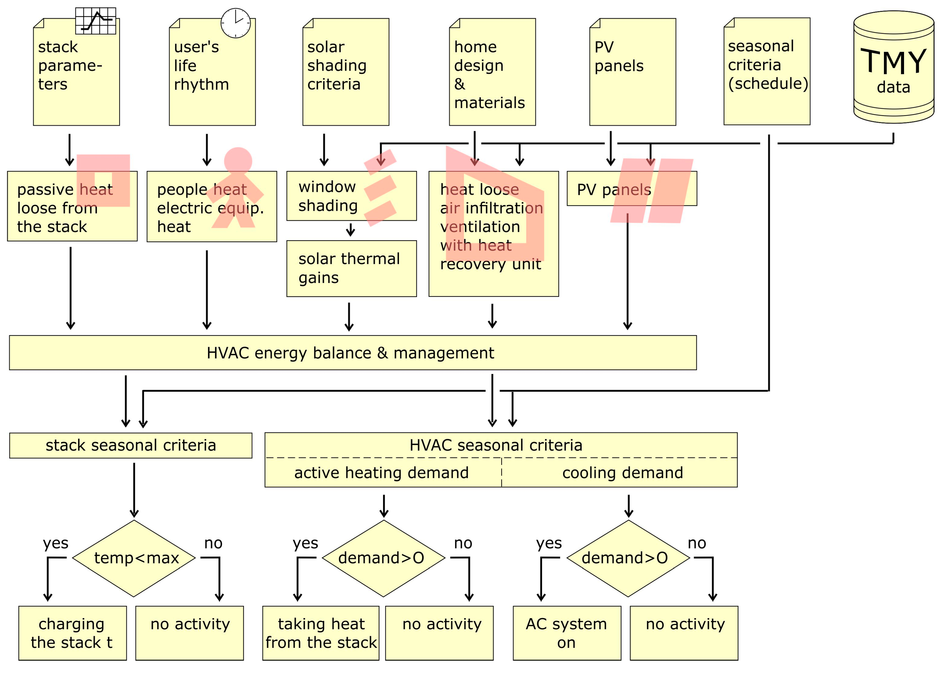
Ventilation heat recovery was assumed at a level of 80%. Heat gains from the residents and working electrical devices were considered for the purpose of calculating the work balance of the air-conditioning system in the summer. In order to carry this out, a 24 h plan of the time that people stay in the rooms of the building, including the type of activity that they perform, was created. A similar schedule was prepared for typical building equipment, i.e., high-power electrical devices (kitchen stove, oven, microwave oven, dishwasher, washing machine, fridge, electric kettle, vacuum cleaner, computer, lighting, etc.). On the basis of the obtained HEB results (see
Figure 7), it was decided if the HVAC system would take energy from the storage stack and actively heat up the living space in the winter season and also whether it would activate the air-conditioning device in the summer season.
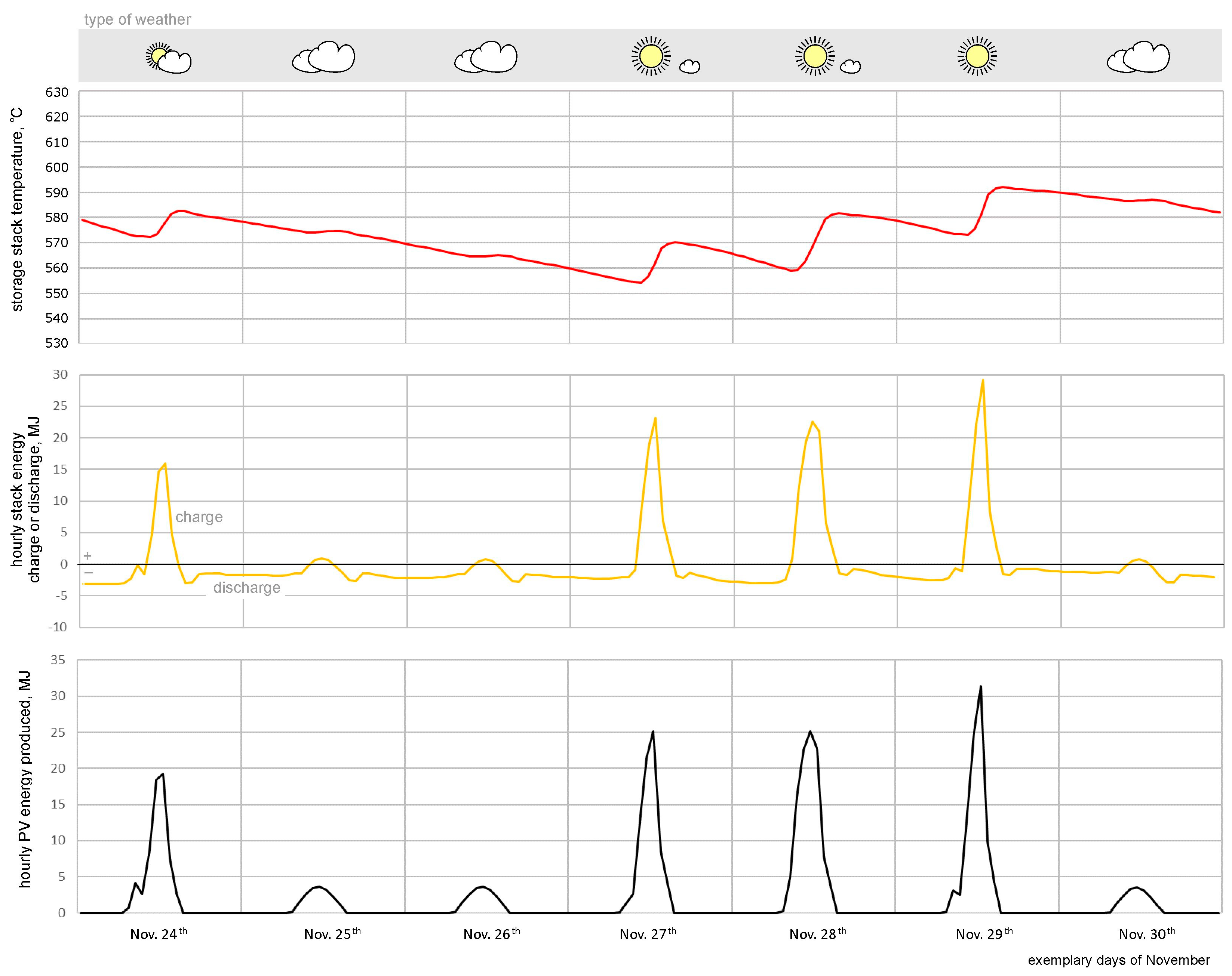
The HEB calculations were carried out in one-hour steps for 24 h of the day, successively for all 365 days of the year. An example of the calculations for selected days in November is shown in
Figure 8. It can be concluded from this figure that the temperature of the storage stack (red line) is variable and that it depends on the current energy balance of the HVAC–PVPSTS installation (yellow line). If the energy balance is negative (in November the building requires heating), the appropriate amount of energy is taken from the storage stack and as a result, the temperature of the storage stack decreases. If the energy balance is positive, which is the case around noon when there is solar radiation on a given day, the PV installation generates significant amounts of electricity, which in turn heats the storage stack and increases its temperature.
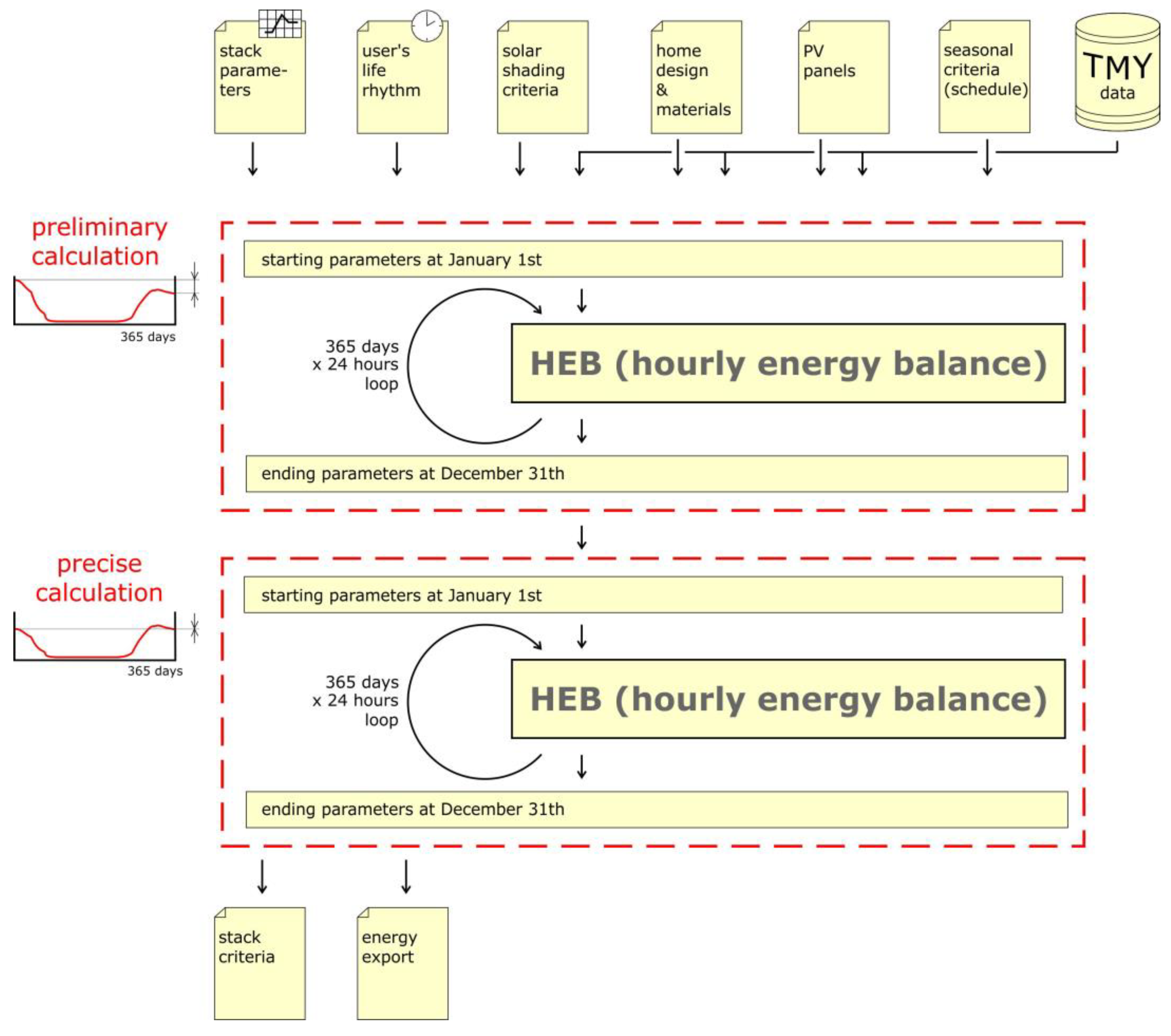
Energy calculations for the whole year require the determination of an appropriately selected value of the storage stack’s temperature (before starting the calculations). A well-selected initial value of the temperature for 1 January, 00:00, occurs when the year calculations end with the same value at 23:00 on 31 December. In order for the calculations to maintain this compliance of temperatures, two cycles of annual calculations were carried out: a preliminary and a precision one, as shown in
Figure 9. In the precision calculation cycle, the value calculated in the preliminary cycle at the end of the year was assumed as the value of the initial temperature of the storage stack. After calculating the temperature for the entire year, the condition of the storage stack was assessed, and the production and export of electricity from the PV installation were summed up.
The adopted method of searching for a solution for the proposed heating system was to search for a storage stack of an appropriate size. The size of the storage stack can be correctly selected by observing the curve of changes in its temperature throughout the year. The storage stack, which is preheated in the autumn, should gradually lower its temperature until the end of the heating period (15 May). In turn, during the heating period, the temperature may fluctuate, depending on the solar radiation that is available in winter. A storage stack that is too small will cool down too quickly, without providing heating at the end of winter, whereas a storage stack that is too large will remain heated until summer, unnecessarily burdening the building’s air conditioning system with its heat losses. The presented calculation method does not allow for simple calculations of how big the storage stack should be; however, it is possible to determine the required size of the storage stack using the “trial-and-error” method. When using this method, it is necessary to determine the values for all the input variables, while at the same time changing only one of them (the size of the storage stack) and evaluating each time whether the obtained results meet the needs of the correct operation of the system.
3. Results and Discussion
After conducting a series of calculations, the correct results were obtained for the ceramic storage stack, the parameters of which are shown in
Table 3.
The entire heat storage (with the obtained external dimensions) fits within the space intended for the storage stack, which is shown by the orange dashed line in
Figure 1. The ratio of the size of the storage stack to the living space of the building is shown in the cross-section in
Figure 10.
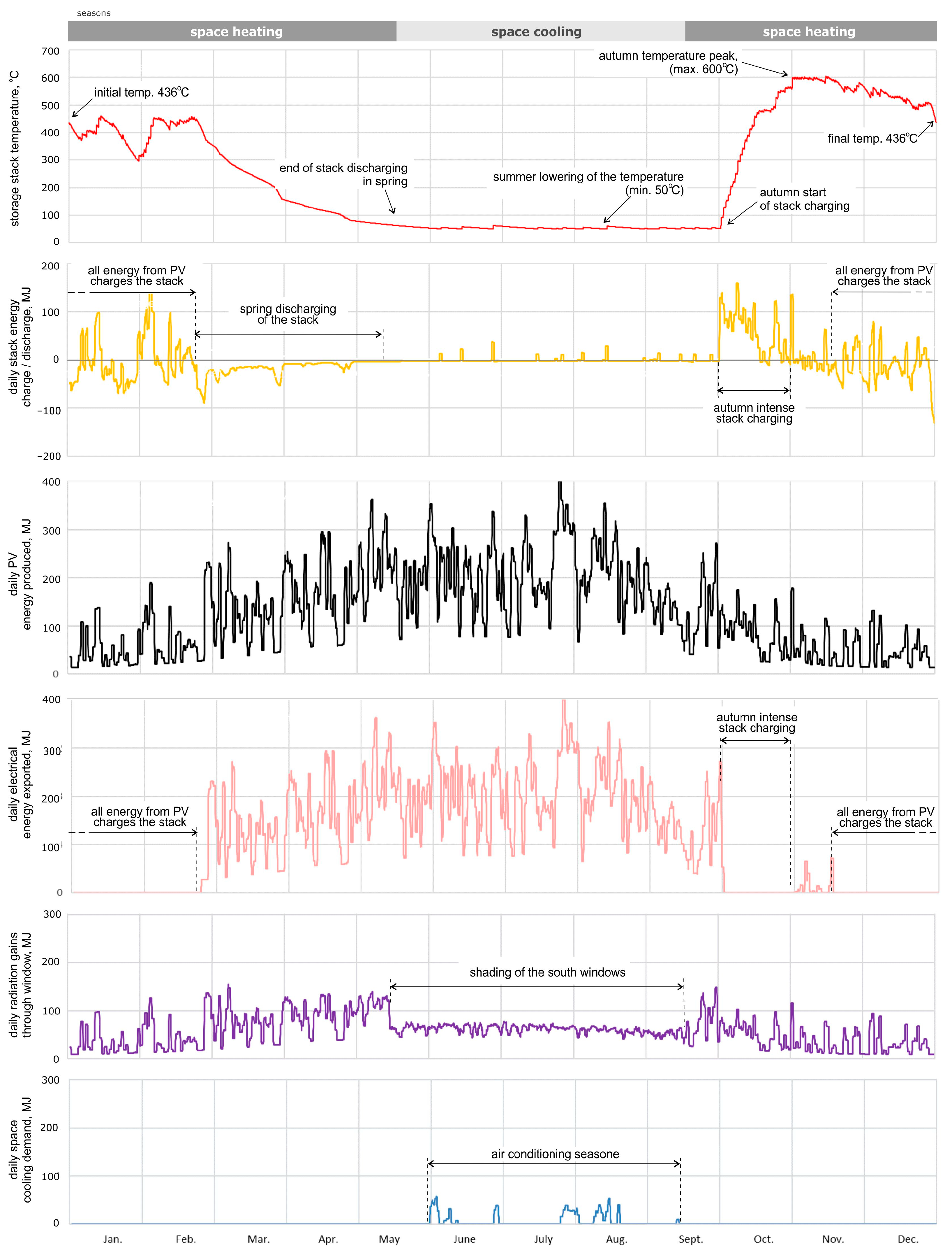
Figure 11 presents the results of the calculations of the installation’s operation over the whole year. The course of changes in the temperature of the storage stack is marked with a red line. It starts with a temperature of 436 °C in the first hour of 1 January and ends with the same temperature in the last hour of 31 December. This means that the calculations were balanced for the whole year and can be considered to be precise. The description of the operation of the installation should start from the last days of September when the storage stack is discharged to the minimum value (at the level corresponding to its temperature of 50 °C).
From the first day of October, the autumn process of charging the storage stack begins. It is an intensive process due to the fact that the storage stack must be fully charged quickly before the winter period. The process of intensive charging of the storage stack lasts for about one month, after which (from the beginning of November to the end of February) the availability of solar radiation significantly decreases, and the building’s heating needs are at their greatest. At this time, the temperature of the storage stack drops, but there are also sunny days when the generated electricity allows for the storage stack to be recharged. As can be seen, the storage stack maintains the necessary state of charging throughout the heating period due to the fact that it cools down only at the beginning of the summer period.
In the diagram (
Figure 11), the yellow line shows the energy that charges the storage stack (positive values) and also the energy that is taken from the storage stack through the ventilation system to heat the living space (negative values). This diagram clearly shows both the moment of the intensive charging of the storage stack in October and the period of the gradual discharge of the storage stack (lasting from March to May). After this time, for the summer months from May to September, the storage stack is kept at its minimum temperature, which aims to facilitate the operation of the air-conditioning system.
The amount of energy produced by the PV installation on the roof of the building is marked in
Figure 11 with a black line. Understandably, with a 30° pitched roof, the largest amounts of energy are generated in the summer and the smallest are generated in the winter. As already mentioned, the electricity generated by the PV installation is only used to heat the storage stack in certain months. These are the months from the beginning of October to the end of February, which can be seen in the diagram (pink line) that shows the electricity exported from the installation to the power grid. This is surplus energy, which is not necessary for the correct operation of the building’s heating system, but instead can be used for the needs of its users, e.g., for the production of hot utility water, the operation of installed electrical devices, and the operation of the air conditioning in the summer.
The amount of solar radiation energy that is acquired passively through the windows of the building is marked in purple in
Figure 11. As can be seen, this energy is relatively level throughout the year, which is due to the vertical position of the windows in the walls, and the lack of windows in the roof’s slope. In addition, in order to aid the work of the air-conditioning system in the summer, 75% of the area of the windows on the south side was shaded when the radiation density exceeded 500 W/m
2. In this case, the graph shows a more than two-fold decrease in passive solar gains in the period from mid-May to mid-September.
The amount of energy needed to cool the building using the air-conditioning system is marked in blue in
Figure 11. It is apparent that such air-conditioning needs occur from June to mid-September, but they are not significant, which is partly due to the window shading system described above. The calculation of the annual energy balance of the installation for the above calculations is presented in
Table 4.
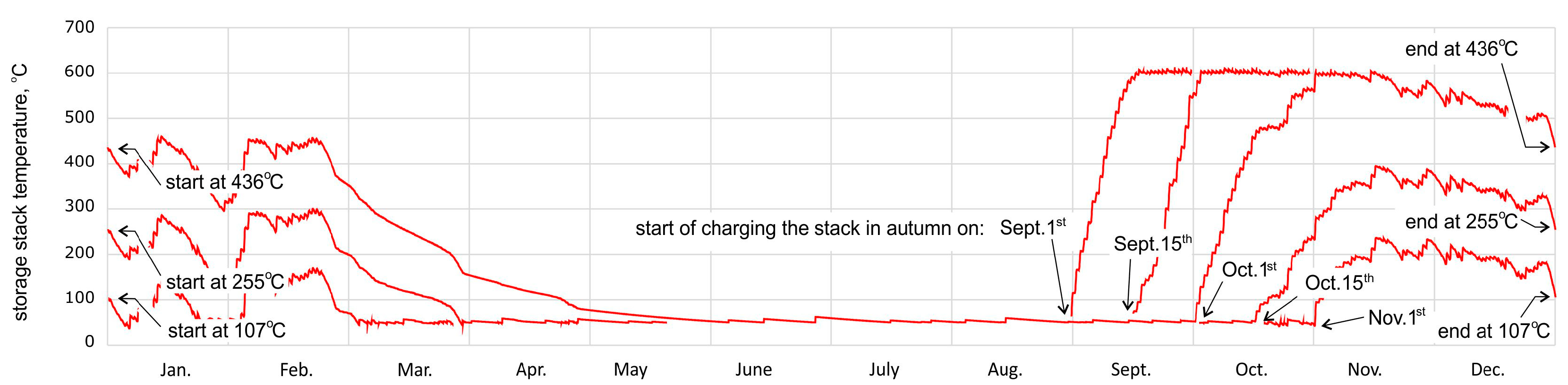
The selection of the day of when to start the intensive charging of the storage stack requires some discussion. Graphs showing the changes in the temperature of the storage stack with regard to the day of starting the charging process are shown in
Figure 12. The conducted analysis covered five different days of when the intensive charging period started:
1 September;
15 September;
1 October;
15 October;
1 November.
When looking at the obtained lines that correspond with the changes in the temperature of the storage stack, it can be seen that the first three moments of the intensive autumn charging of the storage stack have no effect on its temperature in the winter and spring. However, starting the charging of the storage stack from mid-October or later results in its incomplete charging and therefore in an earlier lack of energy at the end of winter. The obtained results concern the calculations made using the TMY database, and it is thus not known what day should be recommended to the user of the considered system (for any real climatic year) for starting the charging of the storage stack. Earlier start times guarantee a greater certainty of its stable operation; however, air-conditioning of the rooms in September and October may still be required. This is due to the passive escape of heat to the living space from the prematurely heated storage stack.
Figure 12.
Influence of the day of when starting the charging of the stack.
Figure 12.
Influence of the day of when starting the charging of the stack.
From the obtained results, it can be seen that it is possible to build an energy installation that ensures stable heating of the building throughout the year. This type of installation is based on an HVAC–PVPSTS system that is powered by a photovoltaic installation located entirely on the roof of the building and also a heat storage stack cooperating with it. The designated size of the heat storage stack fits in the space of the building and does not dominate over the living space. On the basis of the obtained calculations, it was determined that the installation generates approx. 48 GJ (13.3 MWh) of energy, which exceeds (by several times) the heating needs of the building in the winter season (amounting to approx. 10.7 GJ (3.0 MWh)). However, the amount of electricity that can be produced in the winter season is too small, and it is necessary to store some of the required energy in the stack. There is also a need to charge the selected storage stack early enough. Taking into account that some of the exported electricity will be used for the needs of the building’s inhabitants (used electric devices and the production of hot utility water), the energy balance of the installation is still positive and amounts to approx. 11.7 GJ (3.2 MWh), which in turn accounts for 24% of the energy produced by the PV installation per year. It can therefore be concluded that the building in the proposed architectural form, which is equipped with the considered energy installation, is an energy-plus building.
In future research, the authors would like to deal with energy simulations for other locations, as well as the relationship between the upper temperature of the storage stack and its volume. The developed model is also meant to be the basis for the implementation of an experimental facility.


