On the Computation of the Dispersion Diagram of Symmetric One-Dimensionally Periodic Structures


1
Department of Applied Physics 1, ETS de Ingeniería Informática, Universidad de Sevilla, Av. Reina Mercedes s/n, 41012 Sevilla, Spain
2
Department of Electronics & Electromagetism; Facultad de Física, Universidad de Sevilla, Av. Reina Mercedes s/n, 41012 Sevilla, Spain
*
Author to whom correspondence should be addressed.
†
These authors contributed equally to this work.
Symmetry 2018, 10(8), 307; https://0-doi-org.brum.beds.ac.uk/10.3390/sym10080307
Submission received: 13 July 2018
/
Revised: 26 July 2018
/
Accepted: 27 July 2018
/
Published: 1 August 2018
(This article belongs to the Special Issue Symmetry in Electromagnetism)
Abstract
:A critical discussion on the computation of the dispersion diagram of electromagnetic guiding/radiating structures with one-dimensional periodicity using general-purpose electromagnetic simulation software is presented in this work. In these methods, full-wave simulations of finite sections of the periodic structure are combined with appropriate simplifying network models. In particular, we analyze the advantages and limitations of two different combined methods, with emphasis on the determination of their range of validity. Our discussion is complemented with several selected numerical examples in order to show the most relevant aspects that a potential user of these methods should be aware of. Special attention is paid to the relevant role played by the high-order coupling between adjacent unit cells and between the two halves of unit cells exhibiting reflection, inversion, and glide symmetries.
1. Introduction
Many practical microwave/antenna devices find their fundamental operating mechanisms in the behavior of electromagnetic waves in a periodic environment [1,2,3,4]. Examples of this are waveguide/printed-line periodic filters [2,5], metamaterial-inspired transmission lines [6,7], periodic leaky-wave antennas [8], frequency selective surfaces (FSS) [9], reflect/transmit-arrays [10,11], metasurfaces [12], etc. In all these problems, many of the relevant transmission, reflection, and/or absorption characteristics of the periodic (or quasi-periodic) finite device can be explained from the knowledge of the dispersion diagram of the corresponding infinitely periodic structure. As is well known, the treatment of these structures can be reduced to deal only with the unit cell of the periodic structure. Thus, in every of the above mentioned problems we can identify a basic propagation and/or radiation problem involving discontinuities in a generalized waveguiding system subject to periodic boundary conditions. The waveguiding system can be a standard metallic waveguide [2], a generalized waveguide [13,14] (as the one typically found in the treatment of FSSs [15,16]), printed lines [7,17], substrate integrated waveguides [18,19,20], etc. The periodic boundary conditions can appear either in the walls of the waveguiding system (transverse periodicity) and/or along the propagation direction (longitudinal periodicity). If none of the boundaries of the waveguiding system is open to free space, the periodic electromagnetic wave problem can be solved by means of a Floquet analysis of the structure [21,22] that involves only a discrete spectrum [23]. If there are open boundaries in the waveguiding system, the continuous spectrum should also be taken into account by means of its necessary integral representation [3,23,24]. In any case, the dispersion diagram of the periodic structure can be obtained after solving the non-linear eigenvalue problem that results from the application of Maxwell’s equations with the appropriate boundary conditions to the considered unit cell [3,23].
Likewise other non-linear electromagnetic eigenvalue problems, the obtaining of the eigenvalues requires the searching for complex zeros of a given determinantal equation. In the present problem, the eigenvalues correspond to the wavenumbers of the propagating modes, say , with being the phase constant and the attenuation constant ( accounts either for the evanescent/complex nature of the mode or for the presence of material and/or radiation losses). As well reported in the literature, the zero-searching task in the complex plane is not trivial at all because of its intrinsic difficulty to be systematized into a general algorithm that can easily be implemented in an unattended computer code [25,26,27]. Also, to the best of the authors’ knowledge, commercial electromagnetic simulators (for instance [28,29]) provide systematically the frequency behavior of only the real part of the complex wavenumber (an eigenvalue problem is defined by imposing a given phase shift between the boundaries of the unit cell, and the corresponding eigen-frequency is then computed).
As an alternative to solving the above non-linear eigenvalue problem with its intrinsic cumbersome task of searching for zeros in the complex plane, different procedures that make use of general-purpose electromagnetic simulators (or even measurements) have been reported in the literature. One of these procedures involves the analysis of one or two sections of the periodic structure involving several unit cells in order to extract the dispersion relation from the different values of the associated transmission matrices [18,19,30,31,32]. Implicit in the above method is the modeling of the periodic structure as a cascade of identical two-port (or multi-port) equivalent networks [3,4]. The decomposition in two-port equivalent networks is valid when the interaction between adjacent cells is well accounted for by only the fundamental mode of the waveguiding structure. If higher order modes and/or the continuous spectrum take part in this interaction, then multi-port equivalent networks are necessary [3,33]. In many published works on this topic, the application of the above procedures requires the implementation of in-house computer codes [34,35,36]. Usually these codes are not easy to be reproduced by (or distributed to) other authors and also hard to be generalized to cases other than the particular ones treated in the corresponding papers. Certainly, wide distribution and versatility of the software tool are two well-known and very relevant characteristics of commercial electromagnetic simulators. In consequence, the development of combined approaches that can take advantage of these features of commercial simulators and can be complemented with a simple in-house post-processing stage is becoming more and more convenient [37,38,39,40]. Some more-simplified approaches involving the simulation of a single unit cell (or even half unit cell) have also been proposed [41]. Thus, the main goal of the present work will be to go over some of these approaches in order to discuss what is the optimized hybrid method that, making use of commercial software, can efficiently provide the dispersion relation of periodic structures. The presence of internal symmetries in the unit cell will be of special interest in the frame of this research.
The paper is organized as follows. Section 2 gives an overview of two of the most usual methods to deal with one-dimensionally periodic guiding structures and also discusses how to take advantage of the possible symmetries in the unit cell. Section 3 discusses the conclusions derived in the previous section in connection with the numerical results obtained for two different structures: printed periodic microstrip lines and paralle-plate waveguides with periodic corrugations. Finally, a summary of our main conclusions is reported in Section 4.
2. Methods of Analysis
As it has been mentioned above, there are basically two possible rigorous procedures to obtain the dispersion diagram of periodic structures [3,4]: (i) the solution of the corresponding eigenvalue problem associated with a unit cell subject to periodic boundary walls (PBW); and (ii) the extraction of the dispersion curves from the post-processing of the ABCD matrix of a cascade of multi-modal (multi-port) equivalent networks. This second approach is the one reported in the literature when the dispersion diagram of the periodic structure is computed from the full-wave simulation results of a macro-cell made up of several unit cells [18,19,37,38,39], and will be the subject of discussion of the present work. Certainly, the full-wave simulator employed to characterize the macro-cell does take into account all the possible interactions between adjacent cells (which justifies its identification with a cascade of multi-port equivalent networks). This method has several drawbacks such as the intense computational load required to analyze a macro-cell involving many unit cells (as required in many practical problems) [39,41], the appearance of spurious solutions, and the ambiguity of the phase constant outside the first fictitious Brillouin zone imposed by the repetition of the unit cell [39]. These inherent difficulties have motivated the search for approaches that can overcome them, as for example those reported in [39,41]. The procedure given in [39] can solve the drawback related to the appearance of spurious solutions at the expense of increasing the computational load. However, the procedure reported in [41] apparently overcomes all the mentioned drawbacks given that it only involves full-wave simulations of a single unit cell (or even half this unit cell under appropriate symmetry conditions) bounded by electric and/or magnetic walls along the direction of periodicity. Unfortunately, the authors of the present work have not been able to reproduce the expected good results of [41] in their own research and have found some reasons to justify this fact. The theoretical and numerical results of the authors in this research are discussed below.
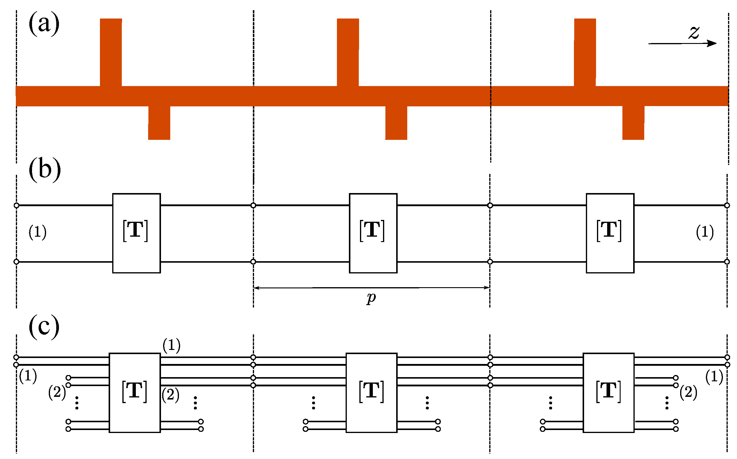
An example of a possible periodic configuration of interest within the frame of the present work is schematically shown in Figure 1a. This arrangement consists of a section of three unit cells of a longitudinally (along z-direction) periodic structure. The figure could represent either the longitudinal cut of a rectangular or parallel-plate waveguide (PPW) with vertical (E-plane) stubs (in such case the solid color represents the interior of the metallic waveguide) or the top view of the layout corresponding to a printed microstrip line periodically loaded with stubs at the right and left sides. In any case, the structure can be modeled by a cascade of equivalent networks as shown in Figure 1b,c. Panel (b) corresponds to a cascade of two-port networks and panel (c) to a cascade of multi-port networks. In Figure 1c it is assumed that port (1) is associated with the fundamental mode, port (2) with the first higher-order mode, and so on. As usual, the input and output ports of the whole structure are associated with the fundamental mode. In the example of Figure 1c, the interaction between adjacent cells is assumed to be accounted for by both the first and second modes, with the remaining modes being considered “localized” modes and therefore only contributing as lumped elements in the equivalent network [15,33,42]. Clearly, the network shown in Figure 1b is a simplification of the one in Figure 1c provided that the fundamental mode is the only relevant mode in the interaction between adjacent cells, as implicitly or explicitly assumed in many works in the literature [43]. Note that although, in principle, the boundaries of the unit cell along the z-direction can be arbitrarily defined (provided the period is respected), it is convenient to set such boundaries far apart from the discontinuities (stubs in this case), in a region where the uniform housing guiding system (rectangular waveguide, PPW or microstrip) is clearly recognizable. If the unit cell has internal symmetries, the boundaries should be chosen in such a way that these symmetries are preserved. Thus, for instance, the limits of the unit cell might have been chosen between the two stubs represented in Figure 1a, but this would not be a good choice if a model like the one in Figure 1b or Figure 1c is intended to be used.
Next, two commonly used methods reported in the literature to obtain the dispersion relation of waveguiding periodic structures along the longitudinal direction will be presented and critically discussed. Both methods combine full-wave simulations coming from commercial electromagnetic solvers with some post-processing to give the dispersion relation of the structures in a systematic way.
2.1. Method A
For a generic periodic configuration as the one in Figure 1a, and assuming that an appropriate deembedding procedure has been implemented [18,19] to cancel out the undesirable effects caused by the practical feeding of the structure, a very general and efficient method proposed in the literature to obtain the dispersion diagram is based on the full-wave simulation of the finite N-cell structure to obtain, in a first step, the corresponding total transmission matrix associated with the input and output fundamental mode. Here it should again be noted that the boundaries of the unit cell of the structure should conveniently be chosen, if possible, so that most of the interactions between cells is carried out by means of the fundamental mode (the unit cell shown in Figure 1a is an example of this convenient choice). The transmission matrix, , corresponding to a cascade of N unit cells can formally be written as
where stands for the unit-cell ABCD matrix corresponding to the fundamental mode in an scenario where the higher-order mode interaction between cells has been appropriately taken into account. It should be noted that, only under this assumption, the cascade of multi-port equivalent networks has formally been expressed as a cascade of “effective” two-port ABCD matrices (as in Figure 1b), which would be computed as
where the subindex p indicates that the elements refer to a region of length p (that is, the period of the unit cell). The term “effective” comes along with this matrix to point out that this matrix is not the standard ABCD matrix of an isolated unit cell interacting with adjacent cells only through the fundamental mode (indeed, the “effective” matrix depends on the number of unit cells in the cascade). The dispersion relation of the periodic configuration would then be given by [3,4]
or by the spurious-free procedure given in [39]. In the above equation is the propagation constant, which is related to the wavenumber by .
2.2. Method B
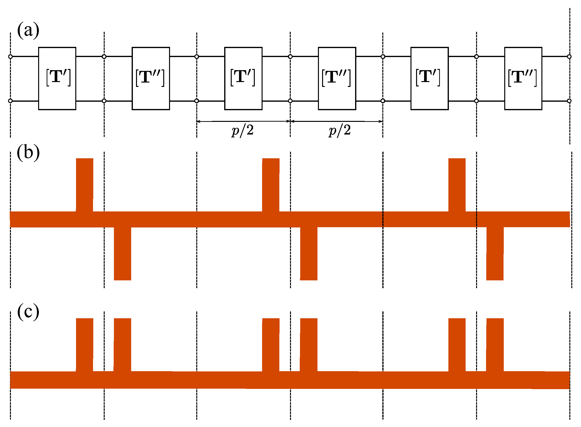
In the above discussion of the periodic generic configuration of Figure 1, it was implicitly assumed that the procedure reported in [41] could not be applied because of the lack of symmetry in the unit cell. However, if the unit cell does have symmetries as those shown in Figure 2b,c, then the authors in [41] propose to exploit such symmetries to express the dispersion relation in terms of the properties of just one half of the unit cell. In general, the smaller the structure to be analyzed with the full-wave simulator, the more accurate and spurious-free the computed numerical solution. Following [41] it will be assumed the existence of a cascade of two-port transmission matrices as in Figure 2a, where the symmetry of the unit cell is reflected by the following form of the matrices:
(subindex stands for the fact that only half the unit cell is considered for the definition of each of these auxiliary transfer matrices). The transmission matrix of the global unit cell is then given by
and the corresponding dispersion relation can be written as
(taking into account the general condition ). If we now consider the identity
it can be concluded that
This dispersion equation is exactly the same as the one given in ([41] Equation (6)) (note that the minimum period was denoted as in [41] and p in this work). In principle we can compute the product from the scattering parameters provided by the full-wave simulation of half the unit cell when considered isolated. However, if we proceed this way, all the higher-order interactions between the two halves of the unit cell would be ignored. (The two-port transmission matrices and should rather be considered again as “effective” transmission matrices, in the understanding that the fundamental mode might not be the only one that contributes to the interaction between the two halves of the unit cell.)
Alternatively we could have proceeded in the manner reported in [41] by introducing a short/open circuit in the structure in order to compute in terms of the auxiliary impedances and defined in [41]. These are the input impedances of the one-port network obtained by substituting the symmetry plane located at the center of the unit cell (see Figure 2) with a short circuit () or an open circuit (). This procedure is found equivalent to starting with the whole unit cell and then applying the even/odd excitation technique [3,4]. As this method implies the setting of electric/magnetic walls at the middle of the structure, both procedures are fully equivalent provided the actual existence of a reflection symmetry plane in the structure that allows for the application of the even/odd excitation procedure. As an example, this symmetry condition is satisfied for the geometry given in Figure 2c but not for the one in Figure 2b. This equivalence, or lack of equivalence, could be irrelevant if it were not for the fact that the presence of electric/magnetic walls in the full-wave simulation is what actually ensures that the higher-order interaction between the two symmetric halves of the unit cell is appropriately taken into account. It is also apparent that the use of these magnetic/electric walls does not imply that the higher-order interaction between adjacent whole unit cells is taken into account, since only one unit cell is indeed analyzed with the full-wave simulator. Moreover, the placing of a magnetic wall in the input port of the half unit cell imposed in [41] does not affect this discussion; actually this magnetic wall is not necessary when the input lumped port is taken at the middle of the unit cell [41] (this fact has repeatedly been checked by many numerical simulations carried out by the authors of the present work). In brief, the technique reported in [41] can, in principle, be applied to geometries of the type shown in Figure 2b,c, but the application of that technique to the geometry in Figure 2b would only account for the electromagnetic interactions between the two halves of the unit cell as long as this interaction is carried out exclusively by the fundamental mode (in other words, the two stubs in each unit cell should be sufficiently far apart so as to ensure the absence of interactions through high-order modes). It leads us to the somehow trivial finding that the higher-order interaction between adjacent cells can only be taken into account by simulating a cascade of multiple unit cells (as done in Method A) or, at most, by taking advantage of reflection symmetry planes (not inversion points, as it is the case shown in Figure 2b) to simulate half the cascade of unit cells terminated with electric/magnetic walls. This result will be numerically studied and validated in next section.
A general conclusion drawn above was that only method A can properly account for high-order interactions between different unit cells, and thus method B should be restricted to those situations where this interaction can be neglected. However, a possible and convenient way to account for the high-order interactions between adjacent cells, which takes advantage of the combination of methods A and B, is to apply method B to an extended cell of period . In this case, the ABCD parameters in (8) would correspond just to the unit cell of period p, which because of the presence of a reflection-symmetry wall in the middle of the extended cell () would lead to a dispersion equation completely equivalent to (3) if N had been set to 2 in method A. Certainly this combined procedure can be applied to cells of more extended periodicity with the purpose of accounting for inter-cell interactions with simulations that only involve half the number of cells.
Interestingly, the above discussion about symmetry in periodic structures turns out to be very relevant when dealing with the circuit modeling of structures with glide/twisted symmetry [44,45]. This topic has recently surged due to some interesting application papers [46,47,48,49], where it is clearly shown that the behavior of periodic structures with glide symmetry is not equivalent to their counterpart without this feature, thus giving an apparent clue on the different role played by the higher-order mode coupling when different types of symmetry are involved. Furthermore, this difference in coupling provided by the glide symmetry has been found to give advantageous features that can enhance the performance of many practical devices [46,48,49]. According to our discussion above, the periodic structure with glide symmetry (whose unit cell incorporates a central inversion point) cannot rigorously be modeled by the analysis of just one of the two subcells of the unit cell (unlike periodic structures whose unit cell does have a reflection symmetry plane). Actually, the authors of [47] claim that their circuit model is valid provided that the upper and lower stubs in ([47], Figure 2c,d) do not overlap. Our premise here is that their proposed simplified circuit modeling of the glide-symmetric structure is valid as long as the upper/lower position of the stubs is irrelevant; namely, when the higher-order coupling between the stubs is not very important. When both stubs overlap this possible difference in the higher-order coupling between upper/lower position is crucial, being less and less relevant as the distance between the stubs increases. In practice, as already reported in [50], there may be many practical situations where just the inclusion of the first high-order mode suffices to obtain accurate results.
Also, the above discussion can be related to a very recent contribution in the circuit modeling of non-symmetrical reciprocal network [51]. Although that paper deals with non-periodic structures, its underlying rationale can easily be extended to the periodic case, in which the general conclusions reached in [51] are found congruent with the discussions reported here.
3. Results
In this section the main issues discussed in previous sections will be numerically validated. First, the general advantage of using Method B will be pointed out when possible. Certainly Method A will provide, in principle, more accurate results since it deals with a more realistic electromagnetic scenario in which many of the couplings between different unit cells are taken into account. However, the unavoidable computational load implicit in the treatment of electrically large and complex structures may lead to very long computational times and non-negligible levels of numerical noise. This last effect can become very relevant when dealing, for instance, with leaky-wave 1-D periodic configurations, where the eventual high radiation leakage in the structure can make the power in the output port several orders of magnitude smaller than in the input port. This numerical noise is also very relevant when computing the attenuation constant of below-cutoff and/or complex modes in closed waveguiding system. A few selected examples will be discussed in the next subsections to clarify these points and provide some insights on the virtues and limitations of the proposed methods.
3.1. Periodic Printed Microstrip Lines
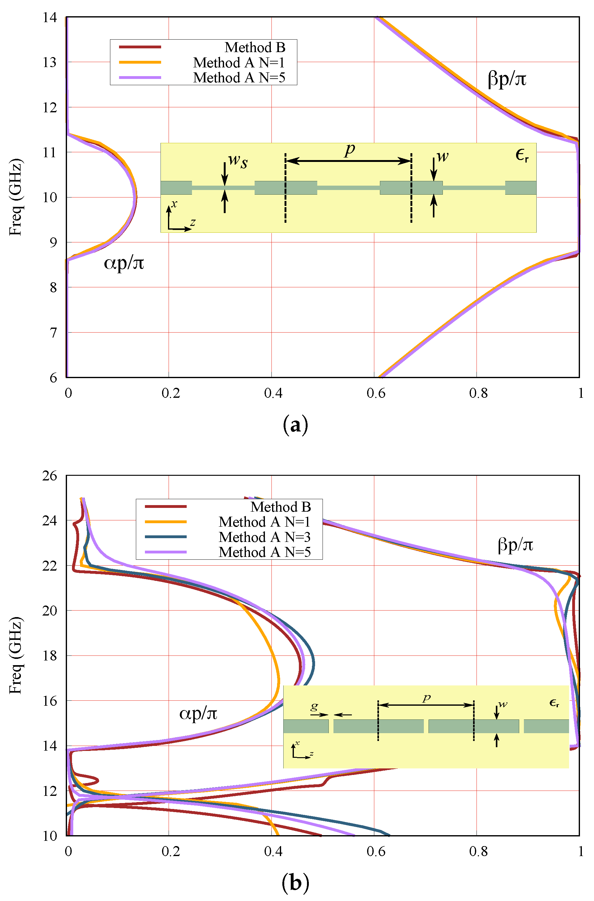
Our first case study in Figure 3 shows the comparison between the results of methods A and B for two printed microstrip lines periodically loaded with inductive/capacitive discontinuities. These lines were previously studied in [38,52] and, in this example, HFSS commercial software [29] has been used for the required full-wave simulations. Both structures exhibit a band gap starting when its period p equals half the line wavelength () (as shown in [35,38]). Although not explicitly shown in the figures, our results agree well with those reported in [38,52].
In Figure 3a the results for the dispersion diagram (both the phase, and the attenuation, , constants) corresponding to method A have been computed using one cell (N = 1) and five cells (N = 5). In this structure, the differences between the N = 1 and N = 5 cases are very small, clearly meaning that the inter-cell coupling is well accounted for by just the fundamental mode. The data corresponding to method B have been obtained by using the even-odd excitation procedure to study the unit cell (namely, just one of the two symmetric halves with electric/magnetic walls are simulated). Certainly, the results using this procedure are found identical to the ones obtained by the procedure proposed in ([41], Equation (12)) as well as to the “Method A N = 1” curve. The excellent agreement between the “Method B” curve and the results with N= 1 can be considered as a first validation of the congruence of methods A and B in this circumstance.
In the structure analyzed in Figure 3b, previously studied in [52], the results provided by method A for one, three, and five cells (denoted as N = 1, N = 3, and N = 5 respectively) are compared with those obtained by method B, taking now an extended period of (namely, the simulated subcell with electric/magnetic walls has a length of p, and thus the obtained results are found to be identical to the case “Method A N = 2”, although this fact is not explicitly shown in the figure since the two corresponding curves would overlap). It is interesting to observe the appearance of slight discrepancies between the results of method A when different number of cells are considered and, furthermore, that a clear convergence pattern is not observed in the analyzed frequency range. These facts are partly attributable to the high values of the attenuation constant in the stopband (there appear values of ), which causes the results with a few cells to be affected by numerical noise due to the very low level of power that reaches the output port (power along z is given by ; that is, an attenuation of , which means dB at 18 GHz, with N being the number of cells in the structure). In this situation, the convenient convergence test to ensure the reliability of the results provided by method A cannot be carried out. Actually, although not explicitly shown in Figure 3b, the results with a higher number of cells are found to increasingly deteriorate.
3.2. Corrugated Parallel-Plate Waveguide
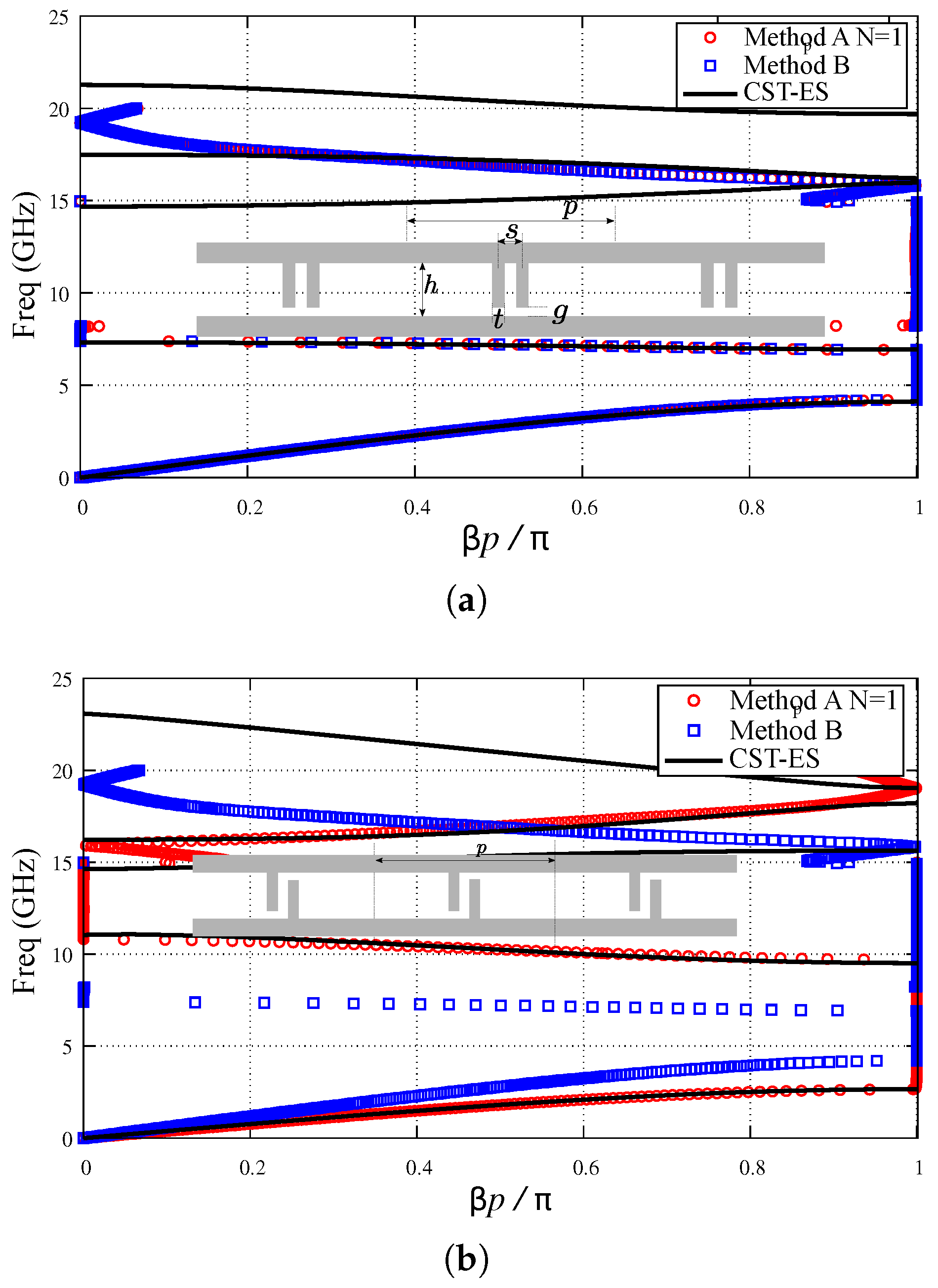
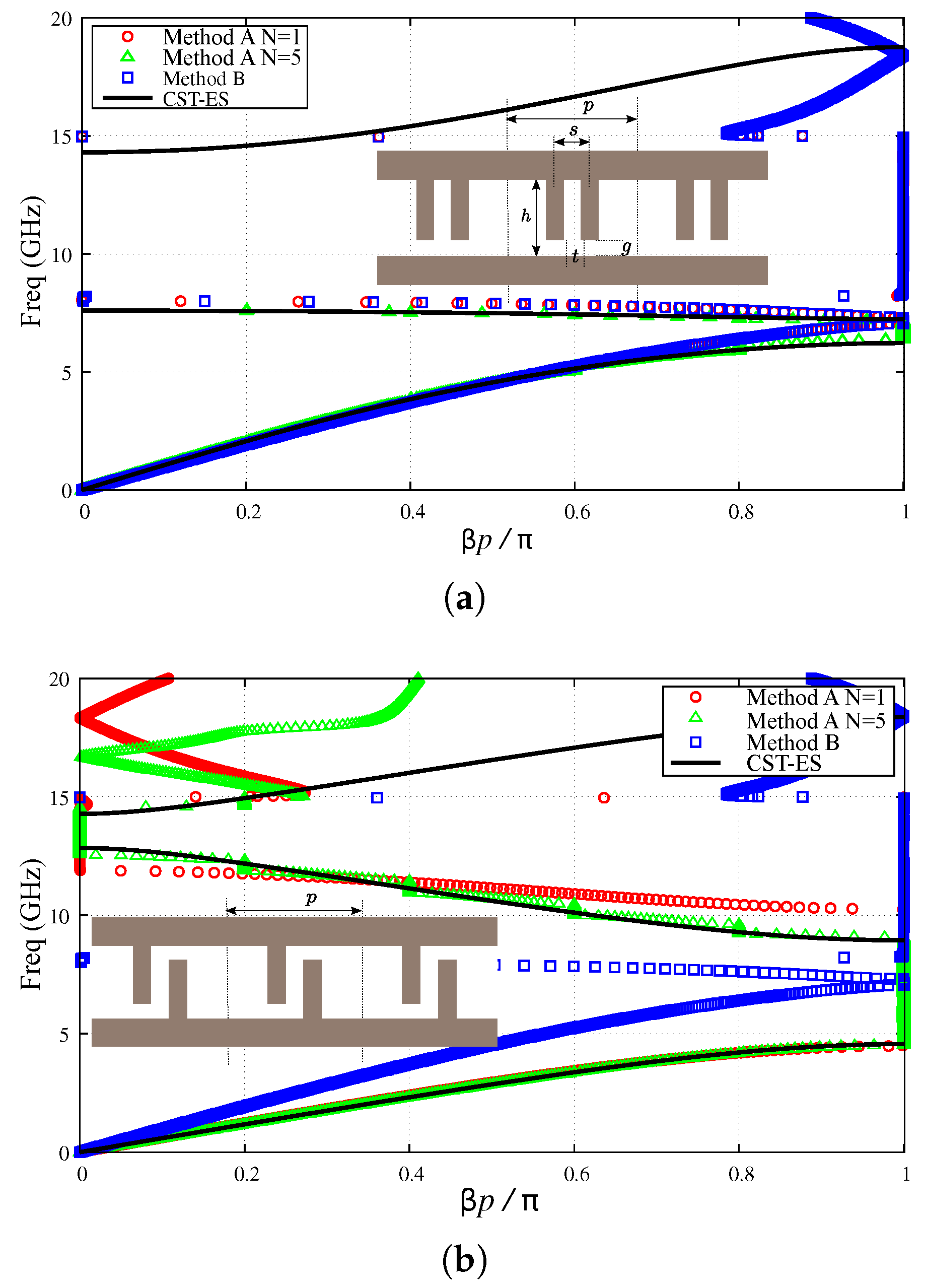
The following example to be examined is a parallel-plate waveguide (PPW) system with periodic metallic corrugations, which can be symmetrically and non-symmetrically distributed, as illustrated by the insets in Figure 4a,b respectively (here the term “symmetrically distributed” is employed to refer only to “reflection symmetry”). First, Figure 4 shows the case where the period of the structure is sufficiently long as to make the inter-cell coupling due to high-order modes almost negligible up to the cutoff frequency of the first high-order mode of the housing PPW. In this frequency range the use of two-port ABCD matrices is well justified and thus the present structure will be taken as a good benchmark to study the intra-cell high-order couplings and its relation to the symmetry properties of the unit cell. In this long period case, no method-A results with are shown since they are found to almost coincide with the case (although some small numerical noise appears because of the inherent more difficult simulation of electrically large structures). Our results will be compared with the data provided by the tool “Eigenmode-Solver” in CST [28]. The results provided by this tool for the frequency behavior of the phase constant are considered very reliable; however, as this tool does not straightforwardly generate results for the attenuation constant of reactive/complex/leaky modes, the comparison for is not carried out.
The reflection-symmetry case studied in Figure 4a clearly shows a very good agreement between the results of method A with just one period () and those given by the even-odd excitation procedure in method B in the whole considered frequency range. These results agree well with the data provided by the CST Eigenmode-Solver (CST-ES) up to 15 GHz; namely, the cutoff frequency of the first high-order mode in the housing uniform (without corrugations) PPW: , with c being the vacuum speed of light and h the height of the uniform PPW. As expected, discrepancies start to appear beyond this frequency, when the presence of this second propagative mode in the uniform sections of the PPW makes that the cascade of two-port ABCD matrices cannot properly account for the unavoidable multi-mode inter-cell coupling that will appear. It should be highlighted that, for frequencies where the regime is no longer monomode in the non-corrugated PPW, the cascade of single two-port transfer matrices is not presumed to work satisfactorily because of the propagative multi-mode nature of the guiding field rather than for possible neglected effects of high-order evanescent modes. Thus, beyond this monomode band, neither method A nor method B are expected to provide accurate results.
Let us now consider the inversion-symmetry structure shown in the inset of Figure 4b. The structure exhibits an inversion point at the center of the unit cell, circumstance that will have interesting consequences for a particular choice of the period, as it will be discussed later. The curves in Figure 4b show again a good agreement within the monomode band between the results of method A and those provided by the CST-ES. However, the data given by method B, which here completely ignores the inversion-symmetry nature of the unit cell, are in full disagreement with the above two set of results. It clearly proves that method B, as expected, drastically fails when high-order coupling between the two subcells forming the inversion-symmetry unit cell is significant and not properly incorporated to the model. This fact seems to be in contrast with the thesis apparently sustained in [41]. Of course, the method would properly work if the subcells only interact through the fundamental propagating mode, as it would be the case for relatively large separation between the stubs. In this latter case the structures with mirror symmetry and with inversion symmetry would have the same response.
Next, the short-period case is studied in Figure 5, where it is again shown the cases corresponding to the presence or absence of a reflection symmetry plane at the middle of the unit cell. In both cases it is now included the data for “Method A N = 5” since high-order inter-cell coupling is expected when the pair of corrugations of each unit cell is electrically close to adjacent ones. Figure 5a shows the symmetrically-distributed case and, again, a perfect agreement is found between “Method A N = 1” and “Method B”. These methods also show a good agreement with the “CST-ES” data in the first passband up to 5 GHz where . For higher frequencies, the inter-cell couplings cannot be well accounted for by the cascade of two-port ABCD matrices and, therefore, the methods are not expected to give accurate quantitative results (although they still provide a good qualitative picture of the band diagram of the structure). The data corresponding to “Method A N = 5” shows a significantly better agreement with the “CST-ES” curve in the whole first passband, although important discrepancies appear in the stopband due to the expected numerical noise caused by the strong attenuation in this band. There is neither a good agreement in the second passband because of the multi-mode nature of the band at higher frequencies. Due to the unreliability of these “Method A N = 5” data outside the first passband, they are not shown in the figure. Regarding the inversion-symmetry case in Figure 5b, the first relevant feature is the complete lack of agreement between the results of “Method A N = 1” and “Method B” even at very low frequencies, which clearly highlights the need of appropriately considering the multi-mode interactions that appear here between the two halves of the unit cell. Since the first passband in this case appears below 5 GHz, a very good agreement is now found between the “Method A N = 1” and “CST-ES”. For higher frequencies there is not such a good quantitative agreement, although the qualitative behavior is approximately captured until the onset of the multi-mode propagation regime. In this inversion-symmetry case, the “Method A N = 5” curve does show a good quantitative agreement within the entire single-band regime, agreement that extends up to the onset of the multi-mode regime. An interesting feature of this structure is the widening of the second bandpass of negative-group velocity nature [53], which now extends from 8 to 13 GHz approximately.
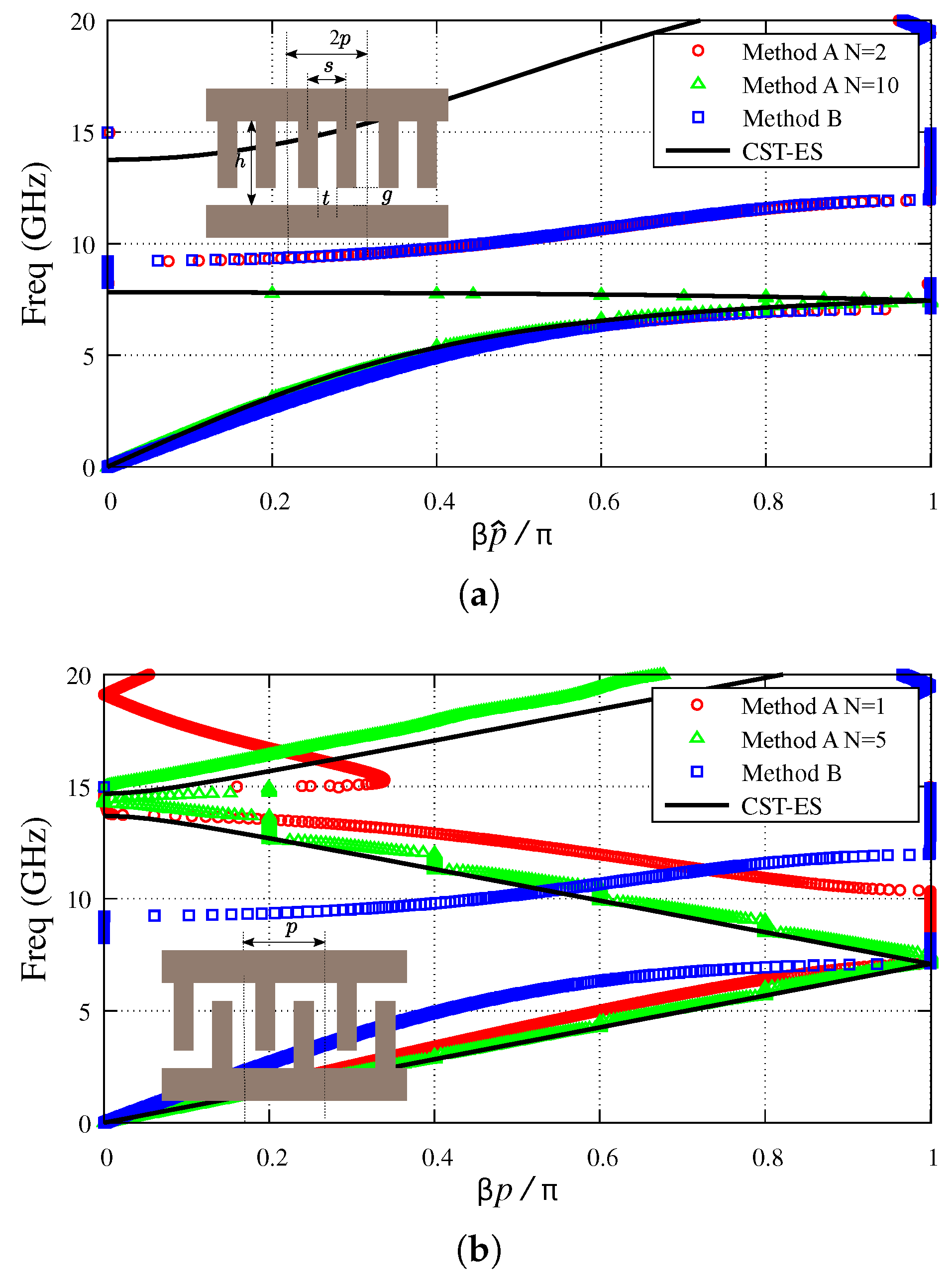
An interesting further step in the study of corrugated PPWs is the case presented in Figure 6, where the period of the structure is taken as twice the distance between the corrugations [47]. Actually, for the symmetrically-distributed corrugation case shown in Figure 6a, the true period of the structure is now , although the dispersion relation will be plotted for an “extended” period for the sake of comparison with the inversion-symmetry case in Figure 6b [the true period of which is ]. The CST-EC curve in Figure 6a shows a first passband that now extends up to about 8 GHz; interestingly, the onset of the second bandstop in Figure 5a. Actually, it is found that the first stopband in this structure disappears as the distance between corrugations approaches the true period of the structure (). In this figure it is also observed that the “Method A N = 2” gives sufficiently accurate quantitative results in this first passband but drastically fails for higher frequencies (in these calculations, a structure with two unit cells, , has been taken). The curve corresponding to “Method A N = 10” only improves the agreement with CST-ES in the first passband but also fails for higher frequencies (the data are not shown). In this case, the expected relevant inter-cell propagative and evanescent high-order coupling would make it necessary either the use of a multi-port approach or the solution of the corresponding non-linear eigenvalue problem to compute the complex propagation constant of the structure. The case considered in Figure 6b is an example of a structure having glide symmetry [46,47,48,49]. The curves of Figure 6b show, similarly to the previous inversion-symmetry unit-cell cases, a great disagreement between the results of Method A (N = 1) and Method B. Rather interesting is the comparison of the “Method A N = 5” and “CST-ES” curves. Now there appears a good agreement between both curves even for frequencies beyond 15 GHz. This good agreement outside the monoband regime is attributed to the fact that the first high-order mode of the housing PPW is not expected to be highly excited in the glide-symmetric structure. The existence of electrically-close periodic inversion points in this structure would presumably reduce the excitation level of modes with an even profile along the vertical direction. Apart from this reasonable good agreement in the quantitative results shown by both curves, they show that the passband of this structure has grown considerably, now extending up to 13.8 GHz. This surprising fact, already reported in [46,47,48,49], is one of the most relevant features of glide-symmetric structures and is likely to find more and more applications in the future (a similar widening of a stopband can also be found in other type of glide-symmetric structures).
4. Conclusions
In this work we have presented a thorough discussion on the pros and cons of computing the dispersion relation of 1-D periodic guiding/radiating structures by means of a combined method that makes use of full-wave simulations data obtained from commercial software tools along with a simplifying equivalent-network model. This method can take advantage of both the high flexibility of simulators to deal with general structures and the further analytical treatment of the data provided by the employed simplified electromagnetic model of the problem as a cascade of two-port equivalent networks.
Some general conclusions that have been discussed in this work are summarized below:
- The most general and reliable method to compute the dispersion diagram of periodic structures is the solution of Maxwell’s equations in the unit cell of the structure subject to periodic boundary conditions. The major disadvantage of this eigenvalue approach is that it involves the searching for complex zeros, a task that is not easily systematized in the form of general-purpose computer codes.
- The so-called Methods A and B in Section 2 are alternative combined approaches that avoid the searching of complex zeros. If the unit cell of the periodic structure has a reflection-symmetry plane, then a further combination of these two methods is proposed as a very convenient and efficient tool.
- Due to the simplification implicit in the modeling of the periodic structure as a cascade of two-port equivalent networks, the possible excitation of high-order propagative modes in the uniform sections of the housing structure will restrict the application of this technique to the so-called monoband regime.
- The combined technique would need to deal with structures with many unit cells in order to take into account the possible inter-cell coupling due to high-order evanescent modes. When inter-cell coupling due to either propagative or evanescent high-order modes can be neglected, this method is always expected to work properly.
- In contrast with the above fact, some authors have claimed that the convenient treatment of just one unit cell would suffice if a proper even-odd periodic excitation technique is applied. In this work it is discussed that this methodology can be used reliably only when there is a reflection-symmetry plane in the unit cell or the interaction between the two halves of the unit cell is carried out by only the fundamental mode.
- Finally, it has also been discussed that glide-symmetric structures, whose interesting properties have recently been the object of intensive study, will require the modeling of the unit cell as a multi-port equivalent network or the solution of the corresponding rigorous eigenvalue problem.
Author Contributions
The contributions of all of the authors were the same. All of them have worked together to develop the present manuscript.
Funding
This research was funded by [the Spanish Ministerio de Ciencia, Innovación y Universidades with European Union FEDER funds] grant number [TEC2017-84724-P].
Acknowledgments
The authors would like to express their gratitude to Alejandro Martínez-Ros for his contribution in the first steps of the present work.
Conflicts of Interest
The authors declare no conflict of interest.
Abbreviations
The following abbreviations are used in this manuscript:
| CST | Computer Simulation Technology |
| FSS | Frequency Selective Surface(s) |
| HFSS | High Frequency Structure Simulator |
| PPW | Parallel Plate Waveguide |
References
- Montgomery, C.G.; Dicke, R.H.; Purcell, E.M. Principles of Microwave Circuits; MIT Radiation Laboratory Series; McGraw-Hill: New York, NY, USA, 1948; Volume 8. [Google Scholar]
- Marcuvitz, N. Waveguide Handbook; MIT Radiation Laboratory Series; McGraw-Hill: New York, NY, USA, 1951; Volume 10. [Google Scholar]
- Collin, R. Field Theory of Guided Waves; McGraw Hill: New York, NY, USA, 1960. [Google Scholar]
- Pozar, D.M. Microwave Engineering, 3rd ed.; Wiley: Hoboken, NJ, USA, 2005. [Google Scholar]
- Cameron, R.J.; Kudsia, C.M.; Mansour, R.R. Microwave Filters for Communication Systems; Wiley: Hoboken, NJ, USA, 2007. [Google Scholar]
- Eleftheriades, G.V.; Balmain, K.G. Negative-Refraction Metamaterials: Fundamental Properties and Applications; Wiley: Hoboken, NJ, USA, 2005. [Google Scholar]
- Martín, F. Artificial Transmission Lines for RF and Microwave Applications; Wiley: Hoboken, NJ, USA, 2015. [Google Scholar]
- Jackson, D.R.; Oliner, A.A. Leaky-wave antennas. In Modern Antenna Handbook; John Wiley and Sons: Hoboken, NJ, USA, 2007; Chapter 7; pp. 325–367. [Google Scholar]
- Munk, B. Frequency Selective Surfaces: Theory and Design; John Wiley and Sons: Hoboken, NJ, USA, 2000. [Google Scholar]
- Huang, J.; Encinar, J.A. Reflectarray antennas; Wiley, Inter Science: Hoboken, NJ, USA, 2007. [Google Scholar]
- Gagnon, N.; Petosa, A.; McNamara, D.A. Research and development on phase-shifting surfaces (PSSs). IEEE Antennas Propag. Mag. 2013, 55, 29–48. [Google Scholar] [CrossRef]
- Martini, E.; Maci, S. Metasurface Transformation Theory. In Transformation Electromagnetics and Metamaterials; Springer: London, UK, 2014; pp. 83–116. [Google Scholar]
- Kurokawa, K. An Introduction to the Theory of Microwave Circuits; Academic Press: San Francisco, CA, USA, 1969. [Google Scholar]
- Varela, J.E.; Esteban, J. Characterization of waveguides with a combination of conductor and periodic boundary contours: Application to the analysis of bi-periodic structures. IEEE Trans. Microw. Theory Tech. 2012, 60, 419–430. [Google Scholar] [CrossRef]
- Rodríguez-Berral, R.; Mesa, F.; Medina, F. Analytical multimodal network approach for 2-D arrays of planar patches/apertures embedded in a layered medium. IEEE Trans. Antennas Propag. 2015, 63, 1969–1984. [Google Scholar] [CrossRef]
- Mesa, F.; Rodríguez-Berral, R.; Medina, F. Unlocking complexity with ECA. IEEE Microw. Mag. 2018, 19, 44–65. [Google Scholar] [CrossRef]
- Hong, J.S. Microstrip Filters for RF/Microwave Applications, 2nd ed.; Wiley: Hoboken, NJ, USA, 2011. [Google Scholar]
- Feng, X.; Ke, W. Guided-wave and leakage characteristics of substrate integrated waveguide. IEEE Trans. Microw. Theory Tech. 2005, 33, 66–73. [Google Scholar] [CrossRef]
- Bozzi, M.; Pasian, M.; Perregrini, L.; Wu, K. On the losses in substrate integrated waveguides and cavities. Int. J. Microw. Wirel. Technol. 2009, 1, 395–401. [Google Scholar] [CrossRef]
- Rubio, J.; Gómez-García, A.; Gómez-Alcalá, R.; Campos-Roca, Y.; Zapata, J. Overall formulation for multilayer SIW circuits based on addition theorems and the generalized scattering matrix. IEEE Microw. Wirel. Compon. Lett. 2018, 28, 485–487. [Google Scholar] [CrossRef]
- Collin, R.E.; Zucker, F.J. (Eds.) Antenna Theory; McGraw-Hill: New York, NY, USA, 1969. [Google Scholar]
- Peterson, A.F.; Ray, S.L.; Mittra, R. Computational Methods for Electromagnetics; IEEE Press: New York, NY, USA, 1998. [Google Scholar]
- Dudley, D.G. Mathematical Foundations for Electromagnetic Theory; IEEE Press: New York, NY, USA, 1994. [Google Scholar]
- Felsen, L.B.; Marcuvitz, N. Radiation and Scattering of Waves; Prentice-Hall: Upper Saddle River, NJ, USA, 1973. [Google Scholar]
- Rodríguez-Berral, R.; Mesa, F.; Medina, F. Systematic and efficient root finder for computing the modal spectrum of planar layered waveguides. Int. J. RF Microw. Comput. Eng. 2004, 14, 73–83. [Google Scholar] [CrossRef]
- Kowalczyk, P. Complex Root Finding Algorithm Based on Delaunay Triangulation. ACM Trans. Math. Softw. 2015, 41, 19. [Google Scholar] [CrossRef]
- Zouros, G.P. CCOMP: An efficient algorithm for complex roots computation of determinantal equations. Comput. Phys. Commun. 2018, 222, 339–350. [Google Scholar] [CrossRef]
- CST Microwave Studio. 2017. Available online: https://www.cst.com/products/cstmws (accessed on July 2018).
- ANSYS High Frequency Structure Simulator (HFSS). Available online: https://www.ansys.com/products/electronics/ansys-hfss (accessed on July 2018).
- Sampath, M.K. On addressing the practical issues in the extraction of RLGC parameters for lossy multiconductor transmission lines using S-parameter models. In Proceedings of the Electrical Performance of Electronic Packaging (EPEP), San Jose, CA, USA, 27–29 October 2008; pp. 259–262. [Google Scholar]
- Apaydin, N.; Zhang, L.; Sertel, K.; Volakis, J.L. Experimental validation of frozen modes guided on printed coupled transmission lines. IEEE Trans. Microw. Theory Tech. 2012, 60, 1513–1519. [Google Scholar] [CrossRef]
- Liu, Z.; Zhu, L.; Wu, Q.; Xiao, G. A short-open calibration (SOC) technique to calculate the propagation characteristics of substrate integrated waveguide. In Proceedings of the 2015 IEEE MTT-S International Microwave Workshop Series on Advanced Materials and Processes for RF and THz Applications, IEEE MTT-S IMWS-AMP, Suzhou, China, 1–3 July 2015. [Google Scholar]
- Conciauro, G.; Guglielmi, M.; Sorrentino, R. Advanced Modal Analysis; Wiley: Hoboken, NJ, USA, 1999. [Google Scholar]
- Esteban, J.; Rebollar, J.M. Characterization of corrugated waveguides by modal analysis. IEEE Trans. Microw. Theory Tech. 1991, 39, 937–943. [Google Scholar] [CrossRef]
- Baccarelli, P.; Di Nallo, C.; Paulotto, S.; Jackson, D.R. A full-wave numerical approach for modal analysis of 1D periodic microstrip structures. IEEE Trans. Microw. Theory Tech. 2006, 54, 1350–1362. [Google Scholar] [CrossRef]
- Paulotto, S.; Baccarelli, P.; Frezza, F.; Jackson, D.R. Full-Wave modal dispersion analysis and broadside optimization for a class of microstrip CRLH leaky-wave antennas. IEEE Trans. Microw. Theory Tech. 2008, 56, 2826–2837. [Google Scholar] [CrossRef]
- Mao, S.G.; Chen, M.Y. Propagation characteristics of finite-width conductor-backed coplanar waveguides with periodic electromagnetic bandgap cells. IEEE Trans. Microw. Theory Tech. 2002, 50, 2624–2628. [Google Scholar]
- Zhu, L. Guided-wave characteristics of periodic microstrip lines with inductive loading: Slow-wave and bandstop behaviors. Microw. Opt. Technol. Lett. 2004, 41, 77–79. [Google Scholar] [CrossRef]
- Valerio, G.; Paulotto, S.; Baccarelli, P.; Burghignoli, P.; Galli, A. Accurate Bloch analysis of 1-D periodic lines through the simulation of truncated structures. IEEE Trans. Antennas Propag. 2011, 59, 2188–2195. [Google Scholar] [CrossRef]
- Martínez-Ros, A.J.; Mesa, F. A study on the dispersion relation of periodic structures using commercial simulators. In Proceedings of the 2017 Computing and Electromagnetics International Workshop (CEM), Barcelona, Spain, 21–24 June 2017; pp. 15–16. [Google Scholar]
- Eberspacher, M.A.; Eibert, T.F. Dispersion analysis of complex periodic structures by full-wave solution of even-odd-mode excitation problems for single unit cells. IEEE Trans. Antennas Propag. 2013, 61, 6075–6083. [Google Scholar] [CrossRef]
- Monni, S.; Gerini, G.; Neto, A.; Tijhuis, A.G. Multi-mode equivalent networks for the design and analysis of frequency selective surfaces. IEEE Trans. Antennas Propag. 2007, 55, 2824–2835. [Google Scholar] [CrossRef]
- Kaipa, C.S.R.; Yakovlev, A.B.; Medina, F.; Mesa, F. Transmission through stacked 2-D periodic distributions of square conducting patches. J. Appl. Phys. 2012, 112, 033101. [Google Scholar] [CrossRef]
- Hessel, A.; Oliner, A.A.; Chen, M.; Li, R. Propagation in periodically loaded waveguides with higher symmetries. Proc. IEEE 1973, 61, 183–195. [Google Scholar] [CrossRef]
- Amari, S.; Vahldieck, R.; Bornemann, J. Accurate analysis of periodic structures with an additional symmetry in the unit cell from classical matrix eigenvalues. IEEE Trans. Microw. Theory Tech. 1998, 46, 1513–1515. [Google Scholar] [CrossRef]
- Quevedo-Teruel, O.; Ebrahimpouri, M.; Kehn, M.N.M. Ultra-wideband metasurface lenses based on off-shifted opposite layers. IEEE Antennas Wirel. Propag. Lett. 2016, 15, 484–487. [Google Scholar] [CrossRef]
- Valerio, G.; Sipus, Z.; Grbic, A.; Quevedo-Teruel, Q. Accurate equivalent-circuit descriptions of thin glide-symmetric corrugated metasurfaces. IEEE Trans. Antennas Propag. 2017, 65, 2695–2700. [Google Scholar] [CrossRef]
- Dahlberg, O.; Mitchell-Thomas, R.; Quevedo-Teruel, O. Reducing the dispersion of periodic structures with twist and polar glide symmetries. Sci. Rep. 2017, 7, 10136. [Google Scholar] [CrossRef] [PubMed]
- Ebrahimpouri, M.; Rajo-Iglesias, E.; Sipus, Z.; Quevedo-Teruel, O. Cost-Effective gap waveguide technology based on glide-symmetric holey EBG structures. IEEE Trans. Microw. Theory Tech. 2018, 6, 927–934. [Google Scholar] [CrossRef]
- Naqui, J.; Duran-Sindreu, M.; Fernandez-Prieto, A.; Mesa, F.; Medina, F.; Martin, F. Multimode propagation and complex waves in CSRR-based transmission-line metamaterials. IEEE Antennas Wirel. Propag. Lett. 2012, 11, 1024–1027. [Google Scholar] [CrossRef]
- Abdo-Sanchez, E.; Camacho-Peñalosa, C.; Martin-Guerrero, T.; Esteban, J. Equivalent circuits for non-symmetric reciprocal two-ports based on eigen-state formulation. IEEE Trans. Microw. Theory Tech. 2017, 65, 4812–4822. [Google Scholar] [CrossRef]
- Rodriguez-Berral, R.; Mesa, F.; Baccarelli, P.; Burghignoli, P. Excitation of a periodic microstrip line by an aperiodic delta-gap source. IEEE Antennas Wirel. Propag. Lett. 2009, 8, 641–644. [Google Scholar] [CrossRef]
- Hwang, R. Negative group velocity and anomalous transmission in a one-dimensionally periodic waveguide. IEEE Trans. Antennas Propag. 2006, 54, 755–760. [Google Scholar] [CrossRef]
Figure 1.
Periodic structure under study, period p. (a) Cascade of 1-port equivalent networks; (b) Cascade of multi-port equivalent networks; (c) Possible actual appearance of the physical periodic structure with just 3 unit cells.
Figure 1.
Periodic structure under study, period p. (a) Cascade of 1-port equivalent networks; (b) Cascade of multi-port equivalent networks; (c) Possible actual appearance of the physical periodic structure with just 3 unit cells.

Figure 2.
Periodic structure (period ) with a symmetry plane at the middle of the unit cell. (a) Cascade of 2-port equivalent networks that explicitly takes into account the presence of the symmetry plane in the unit cell; (b) Structure with a point of inversion symmetry; (c) Structure with a plane of reflection symmetry.

Figure 3.
Dispersion diagram of the periodic printed microstrip lines shown as insets. The substrate of the lines has thickness h and relative permittivity . (a) mm, mm, mm, and mm; (b) mm, mm, mm, and mm.
Figure 3.
Dispersion diagram of the periodic printed microstrip lines shown as insets. The substrate of the lines has thickness h and relative permittivity . (a) mm, mm, mm, and mm; (b) mm, mm, mm, and mm.

Figure 4.
Brillouin diagram of a parallel-plate waveguide (PPW) with periodic metallic corrugations (a) symmetrically and (b) non-symmetrically distributed. The inset structures represent longitudinal sections of the PPW’s with the grey color standing for the metallic parts of the structures. Long period: mm. Other parameters: mm, mm, mm and mm.

Figure 5.
Brillouin diagram of a parallel-plate waveguide with periodic metallic corrugations (a) symmetrically and (b) non-symmetrically distributed. Short period: mm. Other parameters: mm, mm, mm and mm.
Figure 5.
Brillouin diagram of a parallel-plate waveguide with periodic metallic corrugations (a) symmetrically and (b) non-symmetrically distributed. Short period: mm. Other parameters: mm, mm, mm and mm.

Figure 6.
Brillouin diagram of a parallel-plate waveguide with periodic metallic corrugations (a) symmetrically [ mm] and (b) glide-symmetrically distributed [ mm]. Other parameters: mm, mm, mm and mm.
Figure 6.
Brillouin diagram of a parallel-plate waveguide with periodic metallic corrugations (a) symmetrically [ mm] and (b) glide-symmetrically distributed [ mm]. Other parameters: mm, mm, mm and mm.

© 2018 by the authors. Licensee MDPI, Basel, Switzerland. This article is an open access article distributed under the terms and conditions of the Creative Commons Attribution (CC BY) license (http://creativecommons.org/licenses/by/4.0/).
Share and Cite
MDPI and ACS Style
Mesa, F.; Rodríguez-Berral, R.; Medina, F. On the Computation of the Dispersion Diagram of Symmetric One-Dimensionally Periodic Structures. Symmetry 2018, 10, 307. https://0-doi-org.brum.beds.ac.uk/10.3390/sym10080307
AMA Style
Mesa F, Rodríguez-Berral R, Medina F. On the Computation of the Dispersion Diagram of Symmetric One-Dimensionally Periodic Structures. Symmetry. 2018; 10(8):307. https://0-doi-org.brum.beds.ac.uk/10.3390/sym10080307
Chicago/Turabian StyleMesa, Francisco, Raúl Rodríguez-Berral, and Francisco Medina. 2018. "On the Computation of the Dispersion Diagram of Symmetric One-Dimensionally Periodic Structures" Symmetry 10, no. 8: 307. https://0-doi-org.brum.beds.ac.uk/10.3390/sym10080307
Note that from the first issue of 2016, this journal uses article numbers instead of page numbers. See further details here.