Article

Twist and Glide Symmetries for Helix Antenna Design and Miniaturization

by
Ángel Palomares-Caballero
1,*,
Pablo Padilla
2,
Antonio Alex-Amor
1,
Juan Valenzuela-Valdés
2 and
Oscar Quevedo-Teruel
3
1
Department of Languages and Computer Science, Universidad de Málaga, 29071 Málaga, Spain
2
Department of Signal Theory, Telematics and Communications, Universidad de Granada, 18071 Granada, Spain
3
Department of Electromagnetic Engineering, KTH Royal Institute of Technology, SE-100 44 Stockholm, Sweden
*
Author to whom correspondence should be addressed.
Submission received: 26 January 2019 / Revised: 17 February 2019 / Accepted: 4 March 2019 / Published: 8 March 2019

Abstract

:
Here we propose the use of twist and glide symmetries to increase the equivalent refractive index in a helical guiding structure. Twist- and glide-symmetrical distributions are created with corrugations placed at both sides of a helical strip. Combined twist-and glide-symmetrical helical unit cells are studied in terms of their constituent parameters. The increase of the propagation constant is mainly controlled by the length of the corrugations. In our proposed helix antenna, twist and glide symmetry cells are used to reduce significantly the operational frequency compared with conventional helix antenna. Equivalently, for a given frequency of operation, the dimensions of helix are reduced with the use of higher symmetries. The theoretical results obtained for our proposed helical structure based on higher symmetries show a reduction of 42.2% in the antenna size maintaining a similar antenna performance when compared to conventional helix antennas.

1. Introduction

Symmetrical structures are present in a huge number of natural phenomena. On occasion, symmetries have a positive impact in the physical response and properties of materials. Therefore, when symmetries are not spontaneously found in nature, engineers have found a manner to tailor them in an artificial manner [1]. The use of symmetrical geometries modifies the physical properties of materials, such as their mechanical, thermal or electromagnetic responses [2]. Among these properties, those related to electromagnetic behaviour are of great importance for conductive materials and dielectric substrates. The electromagnetic properties resulting from configurations with one-dimensional higher symmetries were initially studied in the 1960s and 1970s [3,4]. However, it has been in recent years, with the new developments on computational electromagnetics, that more complex structures, including two-dimensional and three-dimensional higher-symmetric structures, have been studied. These structures have demonstrated new possibilities for the design of microwave and millimeter-wave circuits and antennas [5]. Some of the key advantages of employing higher symmetries in the design of radiofrequency devices are: significant reduction of the frequency dispersion [6], accurate control of the equivalent refractive index [7], control and elimination of stop-bands in periodic structures [8].
A periodic structure possesses a higher symmetry when it is invariant under a translation and another spatial operator such as a rotation or mirroring. Two commonly used higher symmetries are glide and twist symmetries as illustrated in Figure 1. While the extra spatial operator for glide symmetries is a mirroring with respect to a glide line/surface [9,10], for the twist symmetries the operator is a rotation along a twist axis [10,11,12]. Twist symmetry is a more general concept than glide symmetry. For example, when the unit cell is symmetrical along the transversal direction, a 180° twist-symmetrical structure turns out to be glide-symmetrical too.
Twist and glide symmetries were demonstrated to reduce the dispersion of metasurfaces, providing unit cells with a flattened frequency dependence. This is advantageous for the design of wideband microwave devices, such as planar lenses [3]. Also, the use of glide symmetries in metallic holey structures, as reported in [4], increases the bandwidth of the electromagnetic bandgaps. These glide-symmetrical holey structures have been proposed for cost-effective gap waveguide technology at the millimeter-wave frequency range. Additionally, the combination of twist- and glide-symmetrical configurations increases the equivalent refractive index of periodic structures [5], enhances the linearity of the modes, and creates additional stop-bands at given frequencies [10]. In [13], the use of higher symmetries has been applied to produce a multibeam Luneburg lens antenna with low scan-losses and wide bandwidth. Gap waveguides with glide-symmetrical holey EBG structures were proposed in [14], creating cost-effective guiding structures at high frequencies. Using this technology, a wideband phase shifter was proposed in [15]. Finally, low-loss waveguide flanges were proposed in [16], with the use of glide-symmetric holes around the waveguide apertures. In this manner, the leakage at the waveguide joint is avoided. Lastly, a recent work about the application of glide-symmetry in printed double-sided parallel-strip lines demonstrated the potential of glide symmetry to produce low dispersion transmission lines and filter behavior by breaking the symmetry [9].
Here, we proposed the combination of glide and twist symmetries to reduce the size of helix antennas based on the increment of the equivalent refractive that the higher symmetries produce.

2. Materials and Methods

For antenna designs that are based on field guidance and progressive matching towards free space, as is the case in helix-based antennas, the use of higher-symmetrical configurations can be beneficial. In this section, we analyze the electromagnetic effects of including twist and glide corrugations of a metallic flat strip in a helix structure, defining the guidelines for antenna designs.

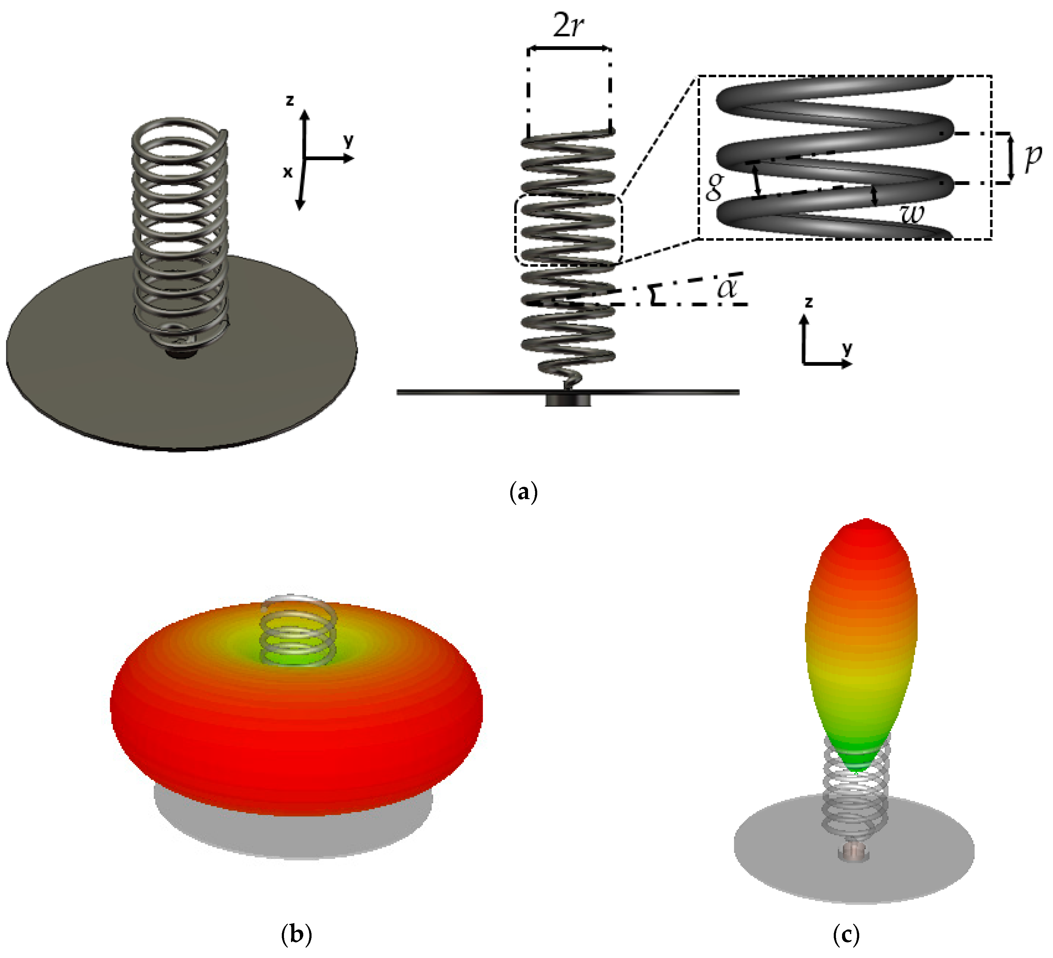
2.1. Baseline Helix Antenna Designs

The general structure of a helix antenna is shown in Figure 2a, and it is formed by a ground plane and a conducting helix structure. The basic parameters that define a helix antenna are: the radius (r), the pitch (p) and the pitch angle (α). The mathematical relation between these parameters is:
p = 2 π r tan ( α )
Depending on these parameters, the antenna can operate in two common modes of radiation: normal and axial mode. The antenna is operating in its normal mode (Figure 2b) if, for a certain working frequency fo, the helix circumference is considerably smaller than the wavelength (2πr << λo) [17]. The polarization in this mode is typically aimed to be circular. The antenna operates in its axial mode if the helix circumference is in the order of the wavelength (2πrλo) and the pitch distance p is a quarter of the wavelength (pλo/4) [18]. Therefore, for the axial mode, the pitch angle must be around 15 degrees, following Equation (1). This mode produces high directivity as illustrated in Figure 2c and provides circular polarization. The use of twist and glide symmetries, depicted in the following subsections, increase the propagation constant. This can be of interest for antenna miniaturization for a given frequency. The miniaturization of the helix antenna in axial mode is useful in applications with space restrictions, such as in antenna arrays.
A helix antenna can be made with a metallic strip instead of a wire. In this case, the strip width w plays a role on the antenna impedance matching [19]. Equations (2) and (3) show the mathematical relations of the pitch length (Lp) and gap between turns (g) regarding the basic helix parameters.
L p = 2 π r cos ( α )
g = p cos ( α ) w
Helix antennas are travelling wave antennas that can be classified as slow-wave since the phase velocity of the wave in the structure is smaller than the speed of light. However, this kind of antennas radiate in the curvatures similar to a conventional helix antenna. This radiation is affected by the discontinuities produced by the corrugations. A classical explanation of the operation of a helix antenna operating in the axial mode is that the radiation is similar to an array of loops whose phase distribution produces an end-fire radiation [20].

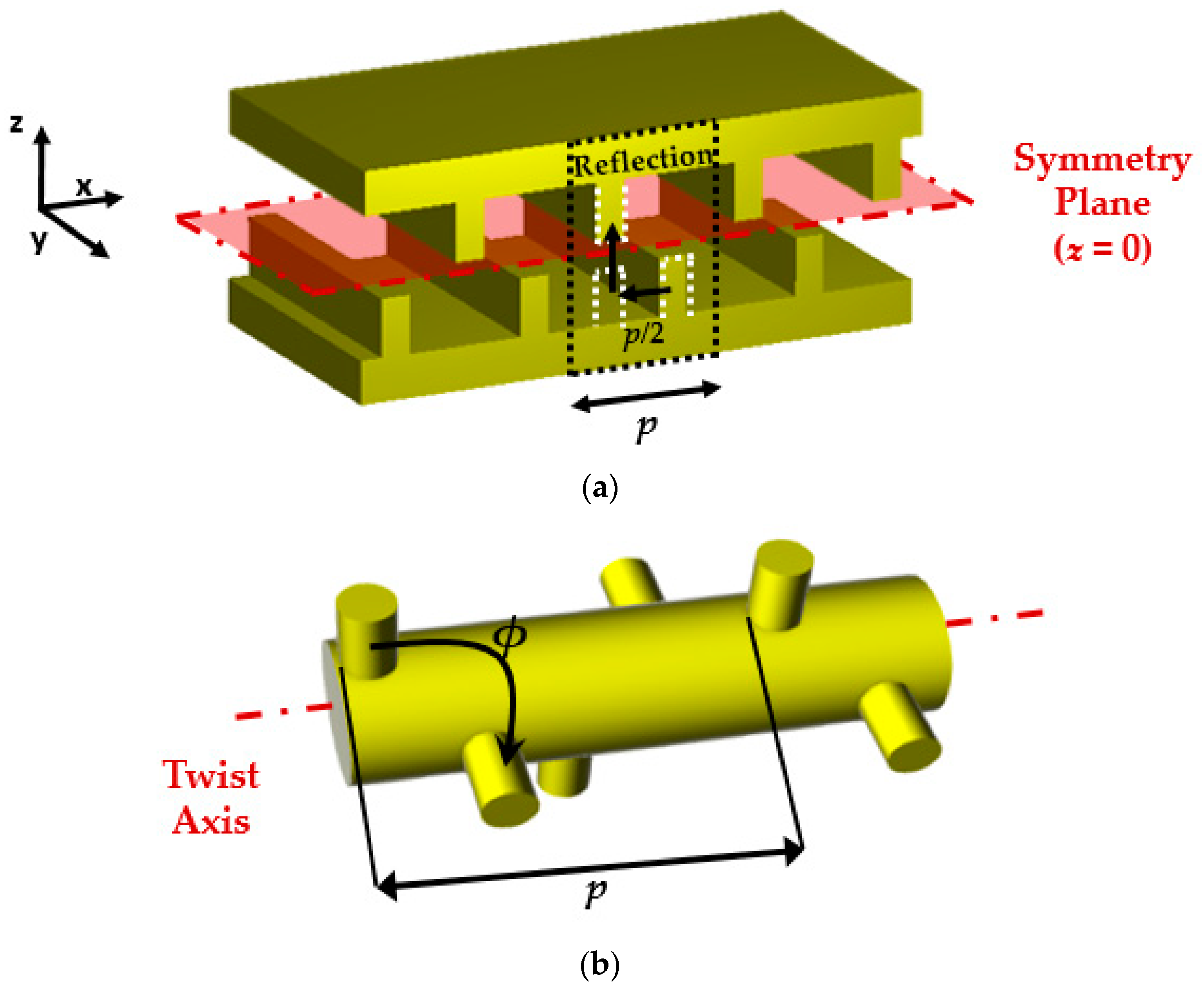
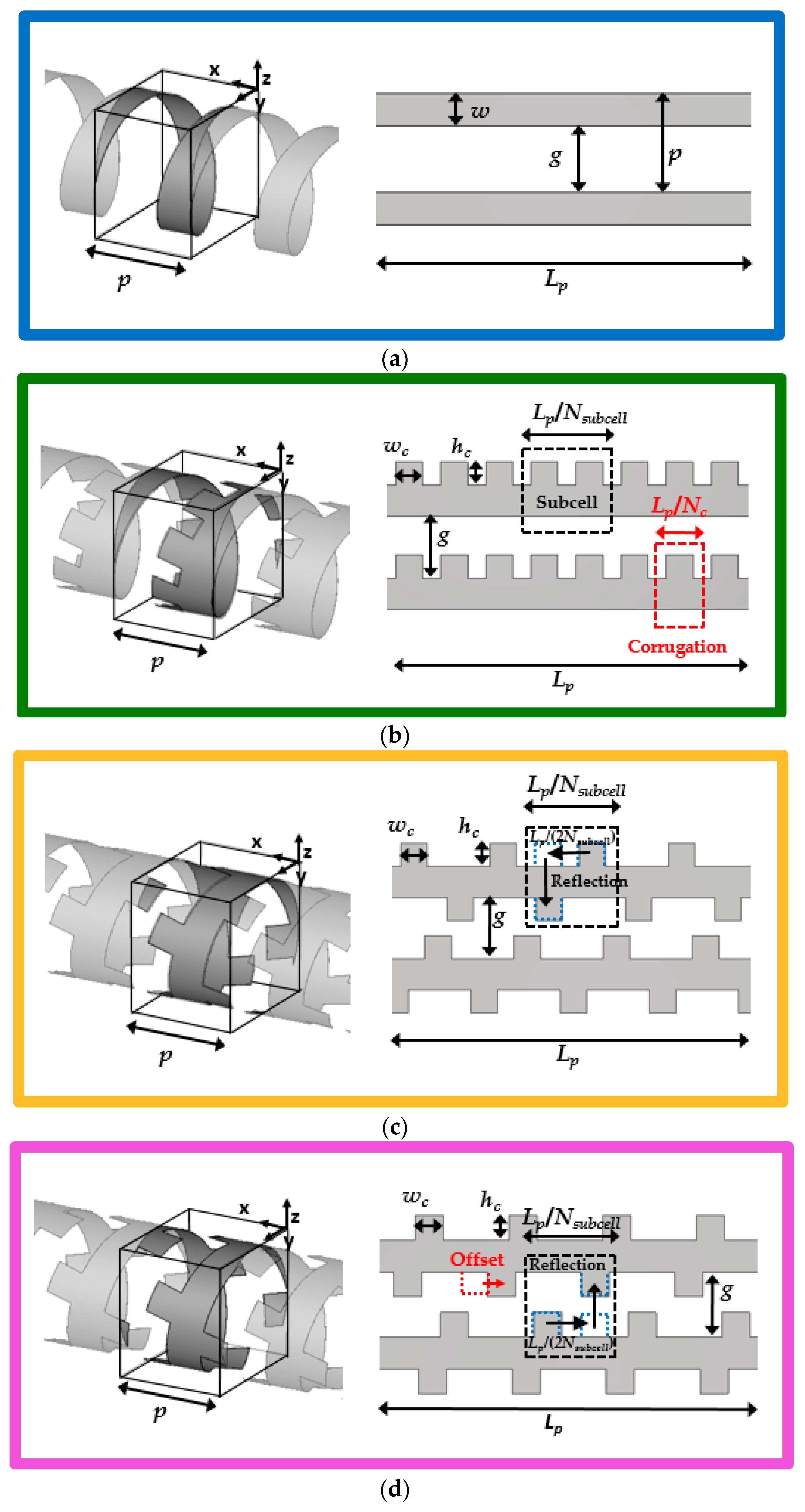
2.2. Periodic Glide-Symmetrical and Twist-Symmetrical Unitary Cells

The unitary cell corresponds to one turn of the helix. The basic parameters to be considered for the baseline periodic cell are: the periodicity (p), the metallic helix strip width (w), the gap space between the wrapped helix strip (g), and the unwrapped length of one turn of the helix strip (Lp). Figure 3a shows the baseline cell both in 3D and in a planar view.
The twist symmetry can be easily introduced to this basic helix cell by adding an integer number of corrugations per cell to any (or both) sides of the strip. These corrugations have inherent twist symmetry due to the helical configuration of the strip. Figure 3b depicts the parameters that characterize the twist-symmetrical strip, which are: the width of the corrugation (wc), its length (hc), and the number of corrugations per unit cell (Nc). The unit cell is composed by sub-cells that consist of a pair of adjacent corrugations.
A twist configuration can be modified to become also a glide. In this case, one corrugation of each pair of the consecutive corrugations is moved to the opposite side of the strip, as illustrated in Figure 3c. In that case, the glide-symmetric periodicity includes a pair of opposed corrugations and its unwrapped length is Lp/Nsubcell. Therefore, the number of glide periods is Nsubcell = Nc/2. It should be noted that, although this configuration is glide in its unwrapped version, once it is rolled, the relation between corrugations of the consecutive turns are not glide. This can be corrected by including a small misalignment (offset) of the corrugations in one of the strip sides so the corrugations of the structure, once wrapped, fit together again. The offset value that satisfies this condition is p·sin(α)-Lp/Nc as illustrated in Figure 3d. Notice that this case keeps a glide configuration, not regarding the strip, but between strip turns.
The electromagnetic behavior of this periodic structure can be characterized with the dispersion diagram of the unitary cell that, in this work, is calculated with the eigenmode analysis of CST Microwave Studio. Since this full-wave electromagnetic solver does not allow eigenmode simulations with open boundary conditions, this requirement in the y and z directions is satisfied by oversizing the simulation box in those directions and imposing an electric wall (Et = 0) at these boundaries. This does not have influence in the frequency range under study since the distance to the box boundaries is much larger than the helix diameter. In the x direction (the direction of the axis of the helix structure), the boundary condition is periodic.
Figure 3a–d provide the schematics under study of the helix unitary cell. Their dispersion diagrams are illustrated in Figure 3e. In this graph, the reference is the dispersion diagram of the helix cell without corrugations (blue line). The twist inclusions in the helix unitary cell increase the propagation constant value, which also becomes almost linear with respect to the frequency for the first propagating mode. Additionally, the closed stop-band between the first and second propagation mode is eliminated. The combination of twist and glide symmetries in the unitary cell slightly increases these effects. The glide case with offset presents similar results for the first mode, as illustrated in Figure 3e, but it permits a further increase of the length of the corrugations without the overlapping between turns.

2.3. Parametric Tuning Effects

The effect of modifying the parameters of the corrugated structure is here studied. This study is aimed to produce general guidelines that will be of use for the design of helix antennas.

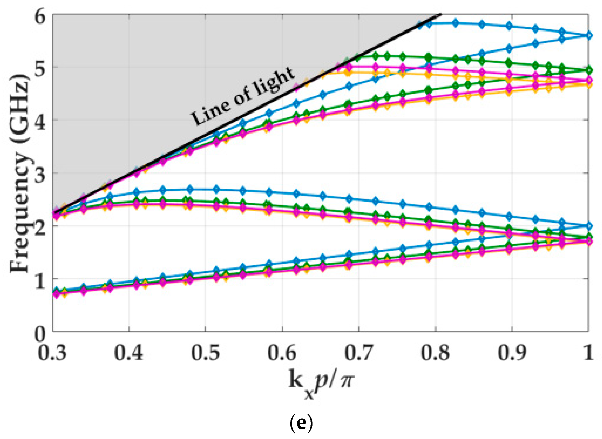
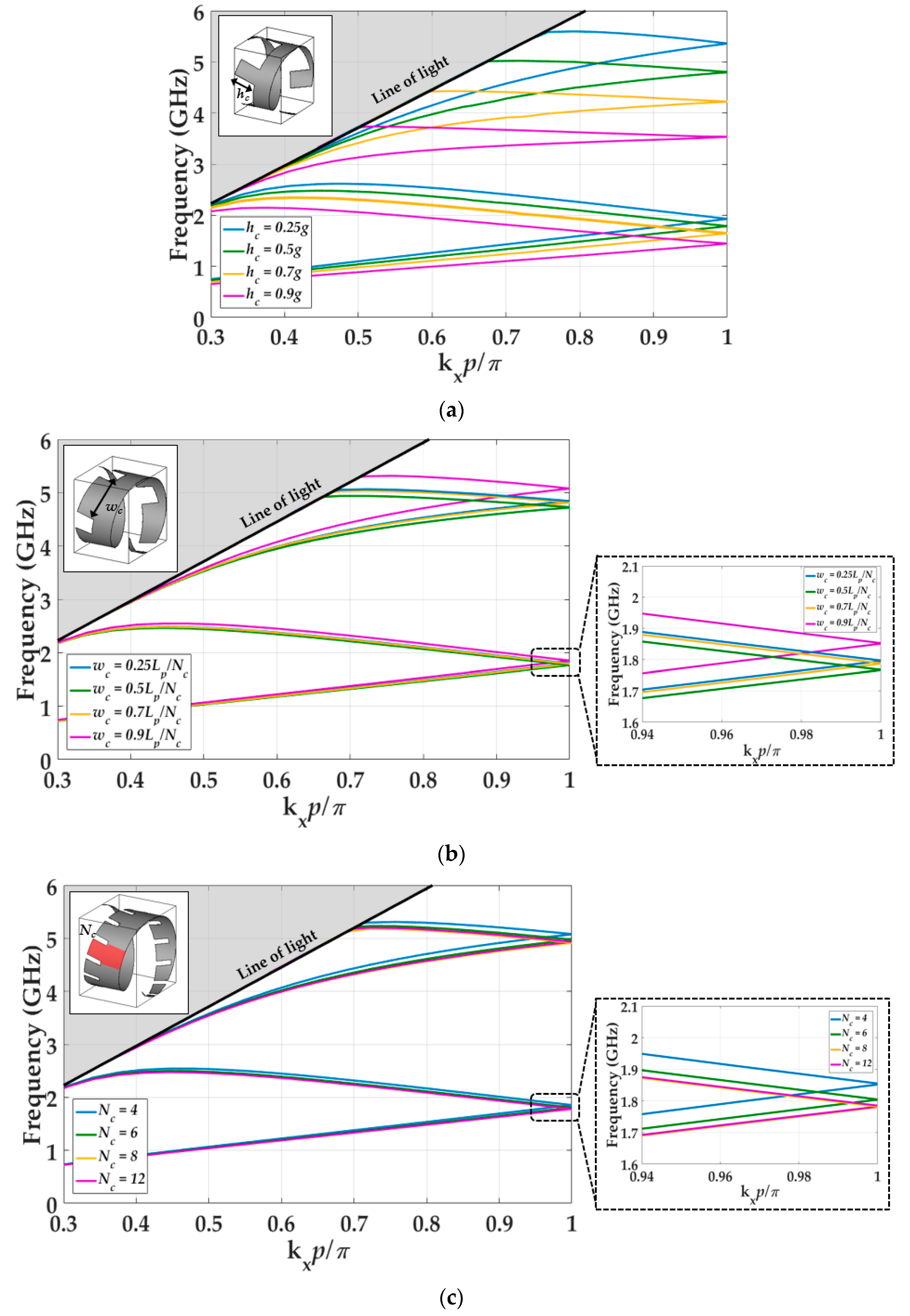
2.3.1. On the Twist Symmetry

The first parametric study, illustrated in Figure 4, is focused on the corrugations of the twist configuration. First, the results for the variation of the length of the corrugations (hc) are depicted in Figure 4a. The increase in the length produces a higher propagation constant, which means an increase of the effective refractive index of the structure. Figure 4b provides the results of modifying the width wc, while preserving the number of corrugations per turn (Nc). This effect is smaller than in the case of the length of the corrugations (hc). In Figure 4c, we illustrate the effect of the number of corrugations per turn (Nc) for a fixed corrugation width. Although the cell periodicity is the same for all the cases, the different dimensions and number of corrugations introduce a variation in the propagation constant. The parametric study carried out in Figure 4c reveals that the increase in the number of corrugations per turn has a small influence in the propagation constant.

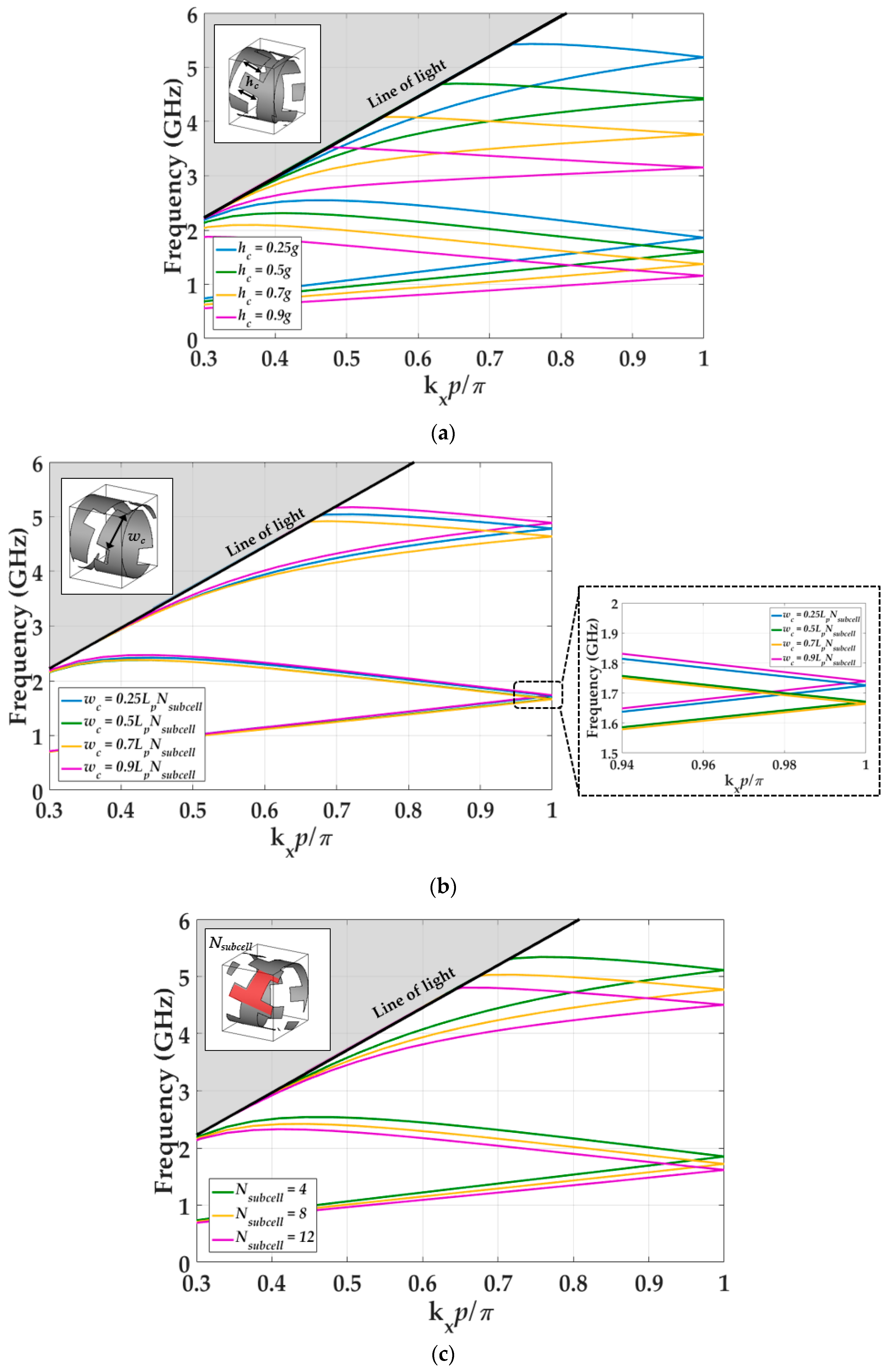
2.3.2. On the Combined Twist and Glide Symmetry

If glide symmetry is added, the effect previously reported in the twist case is enhanced as depicted in Figure 5a. In this configuration, a higher integration between corrugations is possible, so a higher value for the length of the corrugation can be achieved (hc). Variations in the width of the corrugations (Figure 5b) and the number of corrugations (Figure 5c) have a more limited effect.

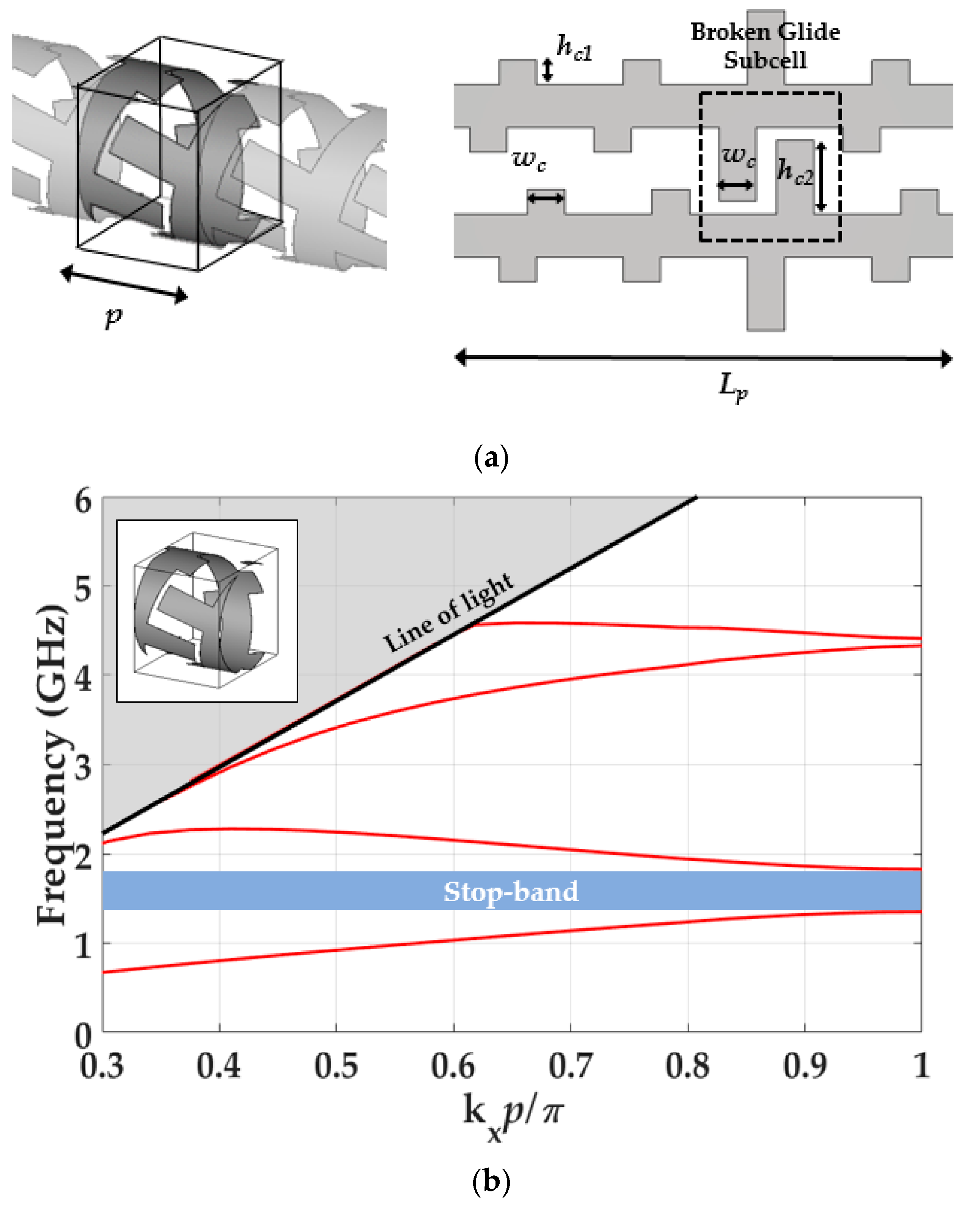
2.4. Symmetry Breakage

Finally we illustrate here the effect of the breakage of the higher symmetry in the structure. The presence of the bandgap when the symmetry is broken is useful for filtering purposes [9]. Although this symmetry breakage can be introduced in different ways, here we only show the effect of one representative case that is depicted in Figure 6a. The breakage is produced by increasing the length of the corrugation of one sub-cell. The dispersion diagram of this structure is illustrated in Figure 6b, in which a stop-band between the first and second modes is generated due to the rupture of the symmetry. Additionally, when the symmetry is broken, the frequency linearity of the propagation constant of the first mode is lost. Notice that in this subsection we only present a brief description of the possibility of breaking the symmetry for filtering purposes, but it is not used in the antenna design. In our specific antenna design, the main goal is miniaturization and filtering is not intended. Therefore, the importance relies in the position of the modes in the dispersion diagram that has to be in a lower position regarding to the position of the modes of the reference helix cell. Including a twist-and-broken glide-symmetrical unit cell in the helix antenna would imply a reduction of the operational bandwidth. Deeper studies regarding symmetry breakage can be found in [9].

3. Helix Antenna Miniaturization

The miniaturization of helix antennas has been the focus of several research studies, mainly for quadrifilar helix antennas [21,22,23,24]. The techniques that have been generally employed for their miniaturization are core dielectric loadings [25,26], meander lines [27] and loading of the pointed ends of the helix arms [28].
A straightforward consequence of increasing the propagation constant of the unitary helix cell is the miniaturization of the resulting helix antenna. A miniaturized helix antenna formed by twist-and-glide unitary cells is expected to radiate similar to a strip-only helix antenna, which is larger in dimension.
The following subsections show the comparison between two helix antenna designs operating at the same frequency. The first design is a conventional axial-mode helix strip antenna and the second design is the equivalent miniaturized twist-and-glide symmetric axial-mode helix antenna. Our proposed technique for miniaturization is fully-metallic, which means that there is no dielectric material in the structure. Therefore, dielectric losses are avoided and our miniaturized antenna can reach higher efficiency and gain at high frequency when compared to miniaturized antennas based on dielectric solutions.

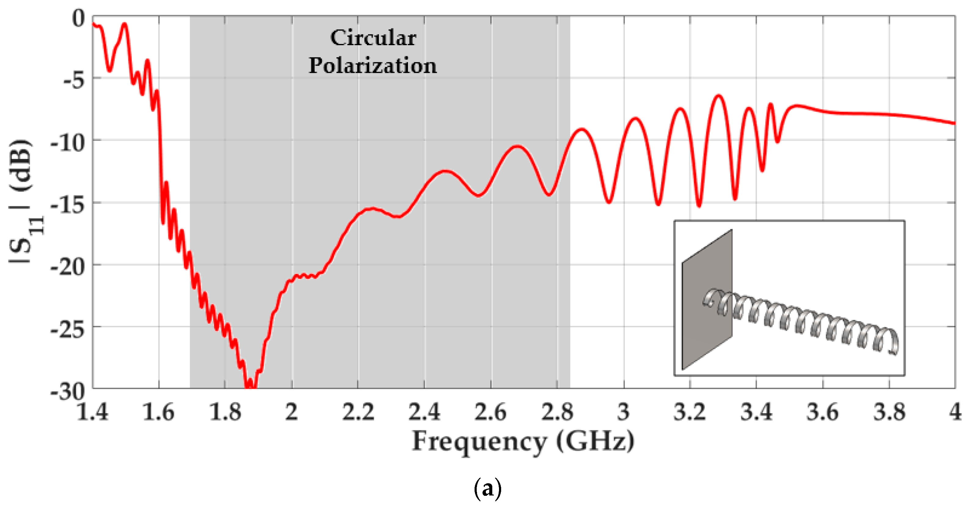
3.1. Conventional Helix Antenna Design

A conventional helix antenna made of strips can be designed based on the principles described in Section 2.1. In this case, the conventional strip helix antenna design has been designed to operate in 2.45 GHz. The radius of the helix is fixed at r = 19.5 mm, which is the parameter that mainly defines the antenna frequency. The pitch angle α has a value of 15 degrees to obtain a radiation in axial mode. The strip width (w) has a value of p/3. This parameter has no noticeable effect in the working frequency. The number of helix turns Nturns is chosen to be 12. A ground plane is located at the bottom of the antenna with a side dimension around one wavelength at the working frequency. A coaxial cable and a standard SMA-type transition, both of 50 Ω, are considered for the antenna feeding. These dimension values for the unit cell imply that the third mode is the one excited in our conventional antenna design.
Figure 7a illustrates the |S11| calculated in CST Microwave Studio. The circular polarization bandwidth is illustrated in grey. The circular polarization bandwidth represents the frequency range where the antenna has an axial ratio (AR) below 3 dB at the main direction of radiation and operates in axial mode.
The conventional helix antenna has an impedance bandwidth (−10 dB of the |S11|) of 54.5%, and an AR bandwidth (below 3dB) of 49%. Figure 7b–d illustrate the 3D radiation pattern of the helix antenna at different frequencies. An end-fire radiation pattern with a high directivity is achieved, as expected for the axial mode.

3.2. Twist-And-Glide Symmetrical Helix Antenna Design

The use of the twist-and-glide symmetrical configuration described in Section 2.3.2 can be used to miniaturize a helical antenna due to their ability to increase the propagation constant. The higher the propagation constant, the larger the effect of the miniaturization. Thus, using the twist-and-glide cell configuration illustrated in Figure 5a, choosing a long corrugation length value, the size reduction of the helix antenna can be remarkable.
The twist-and-glide symmetrical helix antenna has the same feed, ground plane and number of turns than the conventional version described in Section 3.1. The only difference between both antennas is the helical strip radius. The twist-and-glide symmetrical helix antenna radius is fixed to 14.8 mm in order to operate with the axial mode. According to Equation (1) and maintaining the pitch angle at 15 degrees, if the helix antenna radius r is smaller, the pitch period p must be smaller, reducing the length of the antenna. Therefore, this new antenna will have a reduced volume, since its length and radius are both smaller. Again, these dimension values for the unit cell imply that the third mode is the one excited in our miniaturized antenna design.
Figure 8a illustrates the simulated reflection coefficient, including the circular polarization bandwidth. A tapered twist-and-glide unit cell is needed in the first turn of the helix antenna for impedance matching.
The simulation results show an impedance bandwidth of 43.4%. Circular polarization is achieved and the AR bandwidth covers 38% maintaining the central frequency at 2.45 GHz. These bandwidths are slightly narrower than in the case of the conventional helix antenna. The loss in bandwidth in the miniaturized version is caused by the difficulty of matching the corrugated strips. The directivity and size comparisons are illustrated in Figure 9a,b. Both directivity levels are above 12 dBi but the directivity of the miniaturized design is lower due to a smaller antenna’s physical aperture. Regarding the size comparison, the volume size of the conventional helix antenna has been reduced in a 42.2%.

4. Conclusions

In this document, we introduce the use of higher symmetries for helix antenna design. Glide and twist symmetries can be employed to modify the propagation properties of periodic structures by increasing the value of the equivalent refractive index. This effect has been employed here to reduce the size of a helix antenna.
With the use of both twist and glide symmetries, the helix achieves a higher propagation constant of the helix, reducing its operational frequency and yielding a miniaturization in the structure. This effect is mainly controlled by the length of the added corrugations. Here, we have demonstrated a reduction of 42.2% in the antenna volume for a helix antenna operating at 2.45 GHz. Our miniaturized helix design achieves similar antenna performance to a conventional helix design in terms of directivity and AR bandwidth.

Author Contributions

P.P. and O.Q.-T. conceived the concept. Á.P.-C. designed the helix structures and carried out the simulations. A.A.-A. supported with the preparation of the figures. P.P. and J.V.-V. supervised the work. All authors discussed the content and reviewed and edited the manuscript.

Funding

This research was funded by the Spanish Ministerio de Ciencia, Innovación y Universidades with European Union FEDER funds, grant number TIN2016-75097-P, and by Universidad de Granada, under the project PPJI2017.15. Also, this work has been partially supported by the Universidad de Granada through the grant program “Becas de iniciación a la investigación” from Plan Propio de Investigación.

Conflicts of Interest

The authors declare no conflict of interest.

References

  1. Rosen, J. Symmetry in Science: An Introduction to the General Theory; Springer: Berlin/Heidelberg, Germany, 1995. [Google Scholar]
  2. Courtney, T.H. Mechanical Behavior of Materials, 2nd ed.; McGraw-Hill: New York, NY, USA, 2005. [Google Scholar]
  3. Crepeau, P.J.; McIsaac, P.R. Consequences of symmetry in periodic structures. Proc. IEEE 1964, 52, 33–43. [Google Scholar] [CrossRef] [Green Version]
  4. Hessel, A.; Chen, M.H.; Li, R.C.; Oliner, A.A. Propagation in periodically loaded waveguides with higher symmetries. Proc. IEEE 1973, 61, 183–195. [Google Scholar] [CrossRef]
  5. Quevedo-Teruel, O.; Ebrahimpouri, M.; Ghasemifard, F. Lens Antennas for 5G Communications Systems. IEEE Commun. Mag. 2018, 56, 36–41. [Google Scholar] [CrossRef]
  6. Quevedo-Teruel, O.; Ebrahimpouri, M.; Kehn, M.N.M. Ultrawideband metasurface lenses based on off-shifted opposite layers. IEEE Antennas Wirel. Propag. Lett. 2016, 15, 484–487. [Google Scholar] [CrossRef]
  7. Chen, Q.; Ghasemifard, F.; Valerio, G.; Quevedo-Teruel, O. Modeling and Dispersion Analysis of Coaxial Lines with Higher Symmetries. IEEE Trans. Microw. Theory Tech. 2018, 66, 4338–4345. [Google Scholar] [CrossRef]
  8. Ebrahimpouri, M.; Quevedo-Teruel, O.; Rajo-Iglesias, E. Design Guidelines for Gap Waveguide Technology Based on Glide-Symmetric Holey Structures. IEEE Microw. Wirel. Compon. Lett. 2017, 27, 542–544. [Google Scholar] [CrossRef]
  9. Padilla, P.; Herran, L.F.; Tamayo-Dominguez, A.; Valenzuela-Valdes, J.F.; Quevedo-Teruel, O. Glide Symmetry to Prevent the Lowest Stopband of Printed Corrugated Transmission Lines. IEEE Microw. Wirel. Compon. Lett. 2018, 28, 750–752. [Google Scholar] [CrossRef]
  10. Ghasemifard, F.; Norgren, M.; Quevedo-Teruel, O. Twist and Polar Glide Symmetries: An Additional Degree of Freedom to Control the Propagation Characteristics of Periodic Structures. Sci. Rep. 2018, 8, 11266. [Google Scholar] [CrossRef]
  11. Quevedo-Teruel, O.; Dahlberg, O.; Valerio, G. Propagation in Waveguides with Transversal Twist-Symmetric Holey Metallic Plates. IEEE Microw. Wirel. Compon. Lett. 2018, 28, 858–860. [Google Scholar] [CrossRef]
  12. Dahlberg, O.; Mitchell-Thomas, R.C.; Quevedo-Teruel, O. Reducing the Dispersion of Periodic Structures with Twist and Polar Glide Symmetries. Sci. Rep. 2017, 7, 10136. [Google Scholar] [CrossRef]
  13. Quevedo-Teruel, O.; Miao, J.; Mattsson, M.; Algaba-Brazalez, A.; Johansson, M.; Manholm, L. Glide-Symmetric Fully Metallic Luneburg Lens for 5G Communications at Ka-Band. IEEE Antennas Wirel. Propag. Lett. 2018, 17, 1588–1592. [Google Scholar] [CrossRef]
  14. Ebrahimpouri, M.; Rajo-Iglesias, E.; Sipus, Z.; Quevedo-Teruel, O. Cost-effective gap waveguide technology based on glide-symmetric holey EBG structures. IEEE Trans. Microw. Theory Tech. 2018, 66, 927–934. [Google Scholar] [CrossRef]
  15. Rajo-Iglesias, E.; Ebrahimpouri, M.; Quevedo-Teruel, O. Wideband Phase Shifter in Groove Gap Waveguide Technology Implemented with Glide-Symmetric Holey EBG. IEEE Microw. Wirel. Compon. Lett. 2018, 28, 476–478. [Google Scholar] [CrossRef]
  16. Ebrahimpouri, M.; Brazalez, A.A.; Manholm, L.; Quevedo-Teruel, O. Using glide-symmetric holes to reduce leakage between waveguide flanges. IEEE Microw. Wirel. Compon. Lett. 2018, 28, 473–475. [Google Scholar] [CrossRef]
  17. Kraus, J.D. The Helical Antenna. Proc. IRE 1949, 37, 263–272. [Google Scholar] [CrossRef]
  18. Kraus, J.D.; Marhefka, R.J. Antennas for All Applications, 3rd ed.; McGraw-Hill: New York, NY, USA, 2002. [Google Scholar]
  19. Tang, X.; Feng, B.; Long, Y. The Analysis of a Wideband Strip-Helical Antenna with 1.1 Turns. Int. J. Antennas Propag. 2016, 2016, 5950472. [Google Scholar] [CrossRef]
  20. Balanis, C.A. Antenna Theory: Analysis and Design, 3rd ed.; Wiley-Interscience: Hoboken, NJ, USA, 2005; pp. 566–573. [Google Scholar]
  21. Rabemanantsoa, J.; Sharaiha, A. Size Reduced Multi-Band Printed Quadrifilar Helical Antenna. IEEE Trans. Antennas Propag. 2011, 59, 3138–3143. [Google Scholar] [CrossRef]
  22. Takacs, A.; Aubert, H.; Belot, D.; Diez, H. Miniaturisation of quadrifilar helical antenna: Impact on efficiency and phase centre position. IET Microw. Antennas Propag. 2013, 7, 202–207. [Google Scholar] [CrossRef]
  23. Byun, G.; Choo, H.; Kim, S. Design of a Dual-Band Quadrifilar Helix Antenna Using Stepped-Width Arms. IEEE Trans. Antennas Propag. 2015, 63, 1858–1862. [Google Scholar] [CrossRef]
  24. Kazemi, R.; Palmer, J.; Quaiyum, F.; Fathy, A.E. Steerable miniaturised printed quadrifilar helical array antenna using digital phase shifters for BGAN/GPS applications. IET Microw. Antennas Propag. 2018, 12, 1196–1204. [Google Scholar] [CrossRef]
  25. Shi, Y.; Whites, K.W. Miniaturization of helical antennas using dielectric loading. In Proceedings of the IEEE-APS Topical Conference on Antennas and Propagation in Wireless Communications (APWC), Palm Beach, Netherlands Antilles, 3–9 August 2014; pp. 163–166. [Google Scholar]
  26. Neveu, N.; Hong, Y.; Lee, J.; Park, J.; Abo, G.; Lee, W.; Gillespie, D. Miniature Hexaferrite Axial-Mode Helical Antenna for Unmanned Aerial Vehicle Applications. IEEE Trans. Magn. 2013, 49, 4265–4268. [Google Scholar] [CrossRef]
  27. Chew, D.K.C.; Saunders, S.R. Meander line technique for size reduction of quadrifilar helix antenna. IEEE Antennas Wirel. Propag. Lett. 2002, 1, 109–111. [Google Scholar] [CrossRef]
  28. Tawk, Y.; Chahoud, M.; Fadous, M.; Costantine, J.; Christodoulou, C.G. The Miniaturization of a Partially 3-D Printed Quadrifilar Helix Antenna. IEEE Trans. Antennas Propag. 2017, 65, 5043–5051. [Google Scholar] [CrossRef]
Figure 1. Examples of higher symmetries: (a) glide-symmetrical corrugations. The corrugations are periodic along x axis, and the mirroring plane is z = 0; (b) Twist-symmetrical metallic rod with inclusions rotated φ = 90° along the twist axis.
Symmetry 11 00349 g001
Figure 2. Conventional helix antenna composed of a wire and a ground plane: (a) antenna model and scheme; (b) normal mode of radiation; (c) axial mode of radiation.
Symmetry 11 00349 g002
Figure 3. Periodic helix cell: (a) conventional helix (without corrugations); (b) twist-symmetrical helix; (c) combined twist- and glide-symmetrical helix; (d) combined twist-and-glide-symmetric helix with offset in the glide configuration; (e) Their dispersion diagrams. The reference dimensions are: r = 12 mm, α = 15°, p = 20.2 mm, Lp = 78.06 mm, g = 12.78 mm, w = p/3, Nc = 8, hc = 0.4g and wc = 0.3Lp/Nc.
Symmetry 11 00349 g003aSymmetry 11 00349 g003b
Figure 4. Simulated dispersion diagrams for the twist-symmetrical helix cell: (a) modification in the length of the corrugations (hc); (b) modification of the width of the corrugations (wc), while preserving the number of corrugations per turn (Nc = 4); (c) modification of the number of corrugations (Nc), for a given width, wc = 0.06Lp. The reference dimensions are: r = 12 mm, α = 15°, p = 20.2 mm, Lp = 78.06 mm, g = 12.78 mm, w = p/3, hc = 0.4g and wc = 0.3Lp/Nc.
Symmetry 11 00349 g004
Figure 5. Simulated dispersion diagrams for the twist- and glide-symmetrical helix cell: (a) modification of the length of the corrugations (hc); (b) modification of the width of the corrugations (wc), while preserving the number of glide periods (Nsubcell = 4) per turn; (c) modification of the number of glide periods (Nsubcell), for a given width, wc = 0.06Lp. The reference dimensions are: r = 12 mm, α = 15°, p = 20.2 mm, Lp = 78.06 mm, g = 12.78 mm, w = p/3, hc = 0.4g and wc = 0.3Lp/Nc.
Symmetry 11 00349 g005
Figure 6. Symmetry breakage: (a) twist-and-broken glide-symmetrical unit cell; (b) dispersion diagram. The reference dimensions are: r = 12 mm, α = 15°, p = 20.2 mm, Lp = 78.06 mm, g = 12.78 mm, w = p/3, Nc = 8, hc1 = 0.3g, hc2 = 0.9g and wc = 0.3Lp/Nc.
Symmetry 11 00349 g006
Figure 7. Simulated results of a conventional helix antenna in axial mode: (a) |S11| results; (b) 3D radiation pattern in axial mode at 2 GHz (c) 2.45 GHz and (d) 2.8 GHz. The conventional helix unit cell dimensions are: r = 19.5 mm, α = 15°, p = 32.82 mm, w = p/3 and Lp = 126.84 mm.
Symmetry 11 00349 g007aSymmetry 11 00349 g007b
Figure 8. Simulated results of the miniaturized glide- and twist-symmetrical helix antenna centered at 2.45 GHz: (a) Simulated |S11| (b) 3D radiation pattern in axial mode at 2 GHz (c) 2.45 GHz and (d) 2.8 GHz. The twist-and-glide symmetrical unit cell dimensions are: r = 14.8 mm, α = 15°, p = 24.91 mm, w = p/3, Lp = 96.27 mm, Nsubcell = 4, hc = 7.5 mm and wc = 0.3Lp/Nsubcell.
Symmetry 11 00349 g008aSymmetry 11 00349 g008b
Figure 9. (a) Directivity comparison (b) Antenna size comparison. The twist-and-glide symmetrical unit cell dimensions are: r = 14.8 mm, α = 15°, p = 24.91 mm, w = p/3, Lp = 96.27 mm, Nsubcell = 4, hc = 7.5 mm and wc = 0.3Lp/Nsubcell.
Symmetry 11 00349 g009

