Quantum Key Distillation Using Binary Frames


1
Sección de Posgrado de la Universidad Politécnica de Pachuca, Ex-Hacienda de Santa Bárbara, 43830 Zempoala, Hidalgo, Mexico
2
Cinvestav Querétaro, Libramiento Norponiente 2000, Real de Juriquilla, 76230 Santiago de Querétaro, Querétaro, Mexico
*
Author to whom correspondence should be addressed.
Symmetry 2020, 12(6), 1053; https://0-doi-org.brum.beds.ac.uk/10.3390/sym12061053
Submission received: 13 April 2020
/
Revised: 10 June 2020
/
Accepted: 19 June 2020
/
Published: 24 June 2020
Abstract
:We introduce a new integral method for Quantum Key Distribution to perform sifting, reconciliation and amplification processes to establish a cryptographic key through the use of binary matrices called frames which are capable to increase quadratically the secret key rate. Since the eavesdropper has no control on Bob’s double matching detection events, our protocol is not vulnerable to the Intercept and Resend (IR) attack nor the Photon Number Splitting (PNS) attack. The method can be implemented with the usual optical Bennett–Brassard () equipment allowing strong pulses in the quantum regime.
1. Introduction
Quantum cryptography has emerged as a promissory theoretical and technological paradigm for the quantum computing era. This is because the presence of an eavesdropper in QKD protocols produces a detectable disturbance on the quantum communication. Unfortunately, some technological loopholes have been found in the photo-detection system which have imposed new challenges to QKD systems.
Due to those technological loopholes most of the QKD systems have failed to be secure against some of the most challenging attacks: the Intercept-Resend with Faked States (IRFS) attack [1,2,3,4,5,6,7,8,9,10] and the Photon Number Splitting (PNS) attack [11]. IRFS attacks can be partially solved by monitoring the photo intensity at the receiver.
Previously, we have introduced the ack-state protocol in [12,13]. In addition, the nack-state protocol was first discussed in [14]. Such protocols constitute a generalization of the BB84 to resist the PNS attack [13] and the IRFS attack [14], respectively. Both methods are conceived under the basis of a new theoretical approach called quantum flows, denoted by Q [13,15].
In this work, we extend the Q approach to introduce a new distillation method based on binary matrices called frames. It is known that the distillation process generate a few secret bits after a high number of quantum pulses are transmitted from Alice (the sender) to Bob (the receiver).
Several algorithms are applied during the distillation process: sifting, error correction and privacy amplification among others. However, some of them have been developed from other research fields to attend specific requirements. Error correction algorithms are described in [16,17,18,19] and privacy amplification is analyzed in [20]. Up to our knowledge there is no integral method capable to perform the QKD distillation in a single process.
We will introduce here the frame distillation as an integral method for QKD to perform sifting, error correction and privacy amplification just in one process. Surprisingly, we have found that at least theoretically, this technique increases quadratically the size of the secret key allowing to raise up the secret key rate.
2. Related Work
We will describe briefly some reconciliation methods used in QKD, a summary of them is shown in Table 1:
- Binary protocol [16] is a reconciliation method that find and correct errors after the transmission of quantum pulses caused by the noise in the channel and possibly from the eavesdropper. After Alice and Bob obtain an error estimation based on a portion of their sifted key, they determine whether the error failure threshold has been breached. If the error rate is in excess of the fail threshold, Alice and Bob begin the raw key step again. If the estimated error rate is acceptable, Alice and Bob begin the first of a number of passes and use a predetermined random permutation, applying it to the sifted key bits.
- Cascade [17] is a reconciliation method that has become the de-facto standard for all QKD practical implementations. After a number of passes, permutations and cascades, the protocol finishes with low probability that errors still remain [21]. However, large communication overhead have raised methods based on error correcting codes which are more practical.
- The Winnow algorithm [18] is a reconciliation method based on Hamming codes which introduces additional errors because the Hamming algorithm can only reveal one single error in each block.
- LDPC [19] is a linear error correcting code that uses iterative decoding using the sum product soft decision decoder to correct transmission errors.
We conclude this section pointing out some of the challenges of interactive methods that could be summarized from [21] as follows:
- Cascade exhibits great efficiency at low error rates but is still robust up to error rate if required.
- Effective estimation of the error rate in the quantum channel.
- Interactivity could be high intensive in the number of passes to check parity.
- The number of required permutations of the shared bits could demand a persistent computational effort.
3. BB84 Protocol
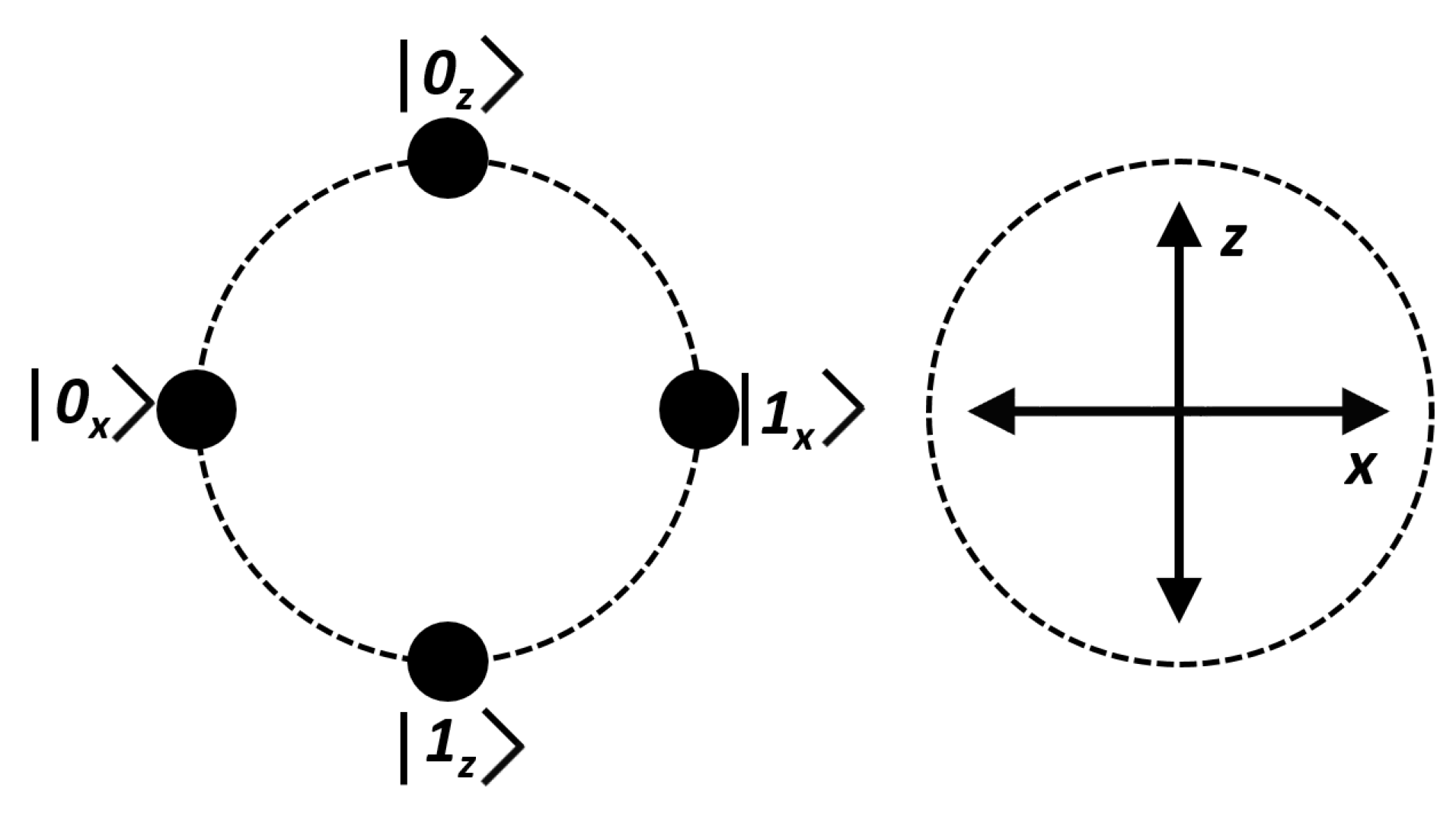
Figure 1 shows the quantum states and measurement bases of BB84 protocol. Here, Alice sends one of the following qubits: , , and . On the other side, Bob detects the incoming state choosing randomly the X or Z measurement basis. Bob’s station is equipped with four optical detectors, one for each qubit. If Bob chooses X to measure or he obtains 0 or 1, respectively and it is said that Bob has performed a compatible measurement because Bob’s measurement basis matches Alice’s preparation basis. Otherwise, if Bob chooses Z to measure or , the measurement is not compatible, the result is ambiguous and it must be discarded. States or behave according to the same principle.
In the BB84 protocol, when a single matching detection event is produced at Bob’s station, the information is derived from the compatible quantum measurement, otherwise the measurement result is ambiguous and it must be discarded.
4. Quantum Flows
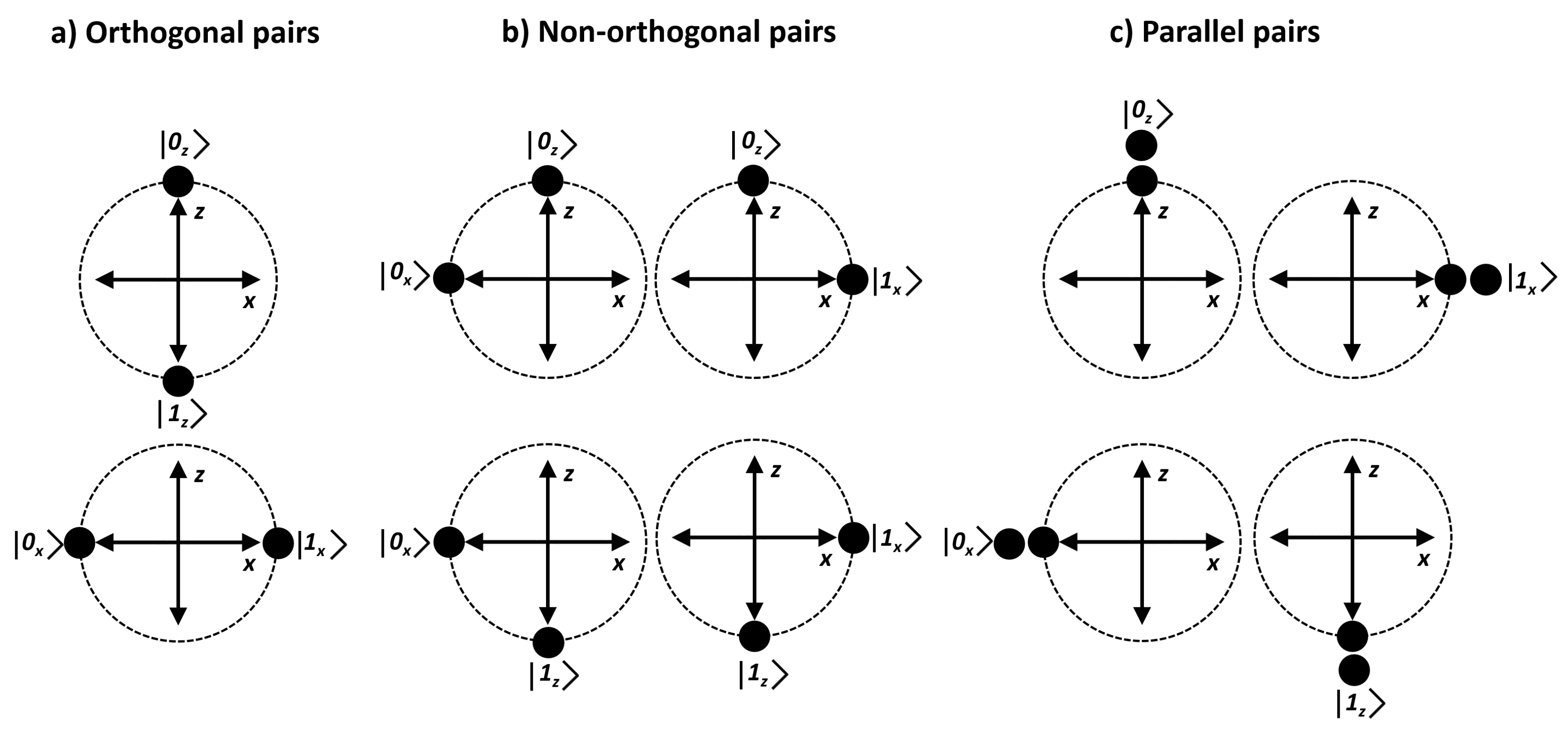
Let us introduce the simplest case of quantum flows approach [13,14]. Here, Alice sends to Bob a pair of quantum states, parallel or non-orthogonal (see Figure 2). The selection between parallel or non-orthogonal pair is performed randomly. On the other side, Bob measures the two quantum states with the same measurement basis, X or Z. If after Bob has measured the pair of quantum states he obtains the same result, a single bit has been successfully transmitted from Alice to Bob. This implies that two quantum states are used to encode a single bit.
After several rounds, pairs of non-orthogonal qubits are interleaved with pairs of parallel qubits. We define that a non-orthogonal quantum flow is interleaved with a parallel quantum flow. This scheme can be generalized to multiple parallel or non-orthogonal states [13,14].
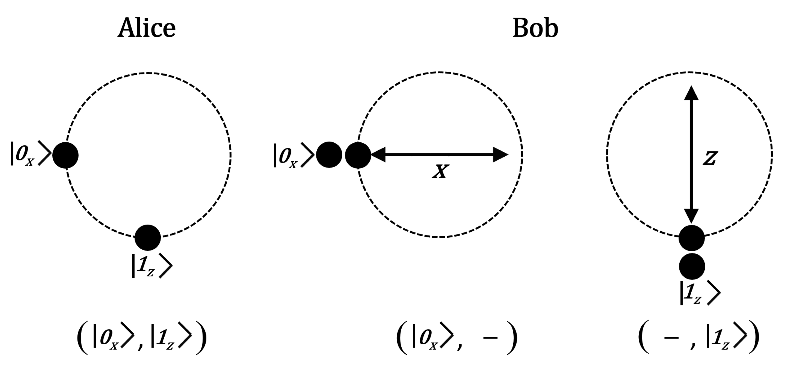
In quantum flows approach, the basic mechanism to transfer information from Alice to Bob is that Alice encodes one bit through a pair of non-orthogonal quantum states. On the other side, the bit is received successfully if a double matching detection event is produced at Bob’s optical station after he measures the pair of non-orthogonal quantum states with the same measurement basis (X or Z), so that the same detector clicks twice (see Figure 3).
Since the two qubits sent by Alice are non-orthogonal and Bob used the same measurement basis, necessarily Bob performs one compatible measurement (the measurement basis that matches the preparation basis chosen by Alice). Although the other measurement is non-compatible, that is, Bob’s measurement basis does not match Alice’s preparation basis, it has probability to produce click at the same detector chosen by Bob. Therefore, in case of a double matching detection event, the transferred bit comes from the compatible measurement. Here, the order between the compatible and the non-compatible measurement is irrelevant for our purposes.
4.1. Measurement of Non-Orthogonal Quantum States
Consider Alice sends to Bob a pair of the non-orthogonal states depicted in Figure 2: (, ), (, ), (, ), (, ). One of the following detection events will be registered at Bob’s optical system:
- Single detection: One of the two qubits is detected at Bob’s station. It could be processed as usually in BB84 protocol. However, in our context, this kind of detection will not be included as part of the distillation process.
- Double detection: The two non-orthogonal states are detected at Bob’s station.
In the matching case, the same detector produces a click for a given pair of non-orthogonal qubits. In the current protocol only this case will be exploited to derive secret bits.
In the non-matching case the qubits are registered at different photo detectors. These kind of results are ambiguous and they are not useful to derive secret bits.
- 3.
- No detection: No pulse is registered.
In case a double matching detection event is produced at Bob’s side, the shared bit comes from the compatible measurement (see Table 2). Therefore, non-matching results are ambiguous and they are not usable to distill secret bits.
For example, Figure 3 shows that Alice prepares and sends to Bob the pair of non-orthogonal states . He chooses randomly to measure both pulses with the X basis (or Z). The two possible double matching detection events are illustrated at right of Figure 3. First, we see the case when Bob chooses X and the double matching detection event produces . The other possibility is that Bob chooses Z and the double matching detection event gives .
This is equivalent to say that exists one bit encoded at each quantum measurement basis, however the transferred bit comes from the measurement basis chosen by Bob that matches the preparation basis chosen by Alice. This kind of quantum measurement is just possible with pairs of non-orthogonal qubits since measurement of parallel qubits using the non-compatible measurement basis will produce ambiguity.
4.2. Quantum Photonic Gains
Not taking into account losses in the quantum channel and the efficiency of optical detection system we can compute the gains of double pulses. In this context, represents the photonic gain of two non-empty pulses, is the gain of the pulses in which is produced a non-empty pulse and one vacuum pulse (whatever the order between them) and is the gain of two consecutive vacuum pulses [15]. Since the gains follow a Poisson’s distribution we can write them in Equation (1).
For example, for we have , and . Therefore, the gain of double pulses reduces considerably. Increasing to raises to . However, the detection system sometimes requires a recuperation time after it can register another detection event, so the probability to get two consecutively pulses reduces even more. Fortunately, quantum states inside a pair of non-orthogonal states can be sent temporally separated as it is represented in Figure 4 (for details see Section 4.2 of [14]).
5. Distillation Based in Non-Orthogonal Quantum States
To explain the distillation process to produce secret bits between Alice and Bob using non-orthogonal quantum states we must introduce a new concept based on binary matrices called frames.
5.1. Frames
Binary frames or simply frames, are binary matrices conceived to implement the sifting, error correction and amplification processes for non-orthogonal quantum states based QKD. We introduced the set of frames enumerated from 1 to 14 in Table 3. We have classified the frames into useful and useless frames but such distinction will be explained later. Each row of a frame contains the qubits of the non-orthogonal pair sent by Alice, basis X to the left, basis Z to the right (see Table 3).
After Bob measures a pair of non-orthogonal qubits and provided he get a double matching detection event, he obtains a bit from the corresponding detector. It means that Bob can obtain just one bit per row inside a frame, thus two bits per frame.
5.2. Matching Results (Mr)
We can see the overall purpose of the protocol saying that Alice transfers a specific frame to Bob. Then, after two matching detection events are produced at Bob’s station, the frame ends in a configuration we call Matching Result (MR). We list in Table 4 the four possible Bob’s Matching Results. Table 4 shows that each Matching Result contains two bits that encode Bob’s MR. The sifting process, we will introduce next, is intended to Alice would be capable to identify successfully Bob’s MR.
5.3. Sifting Protocol
Let us enumerate the first steps of the sifting protocol based on frames:
- Alice prepares and sends to Bob a pair of non-orthogonal qubits over the quantum channel. She chooses a pair randomly between , , and .
- Bob chooses randomly the measurement basis (X or Z) to measure the incoming pair of non-orthogonal qubits.
- After several rounds, using a classical channel, Bob announces to Alice the non-orthogonal pairs that produce double matching detection event (remember that Bob obtains a distribution of single and double detection events, which can be matching or non-matching). As indicated before, the states inside a quantum pair are temporally separated each other, so users must agree previously on the time difference.
These steps are not enough to distill secret bits. Alice needs a method to identify Bob’s Matching Results. Now, let us introduce the sifting bits.
5.4. Sifting Bits Based in the Xor Function
To compute the sifting bits it must be applied the usual xor function to the vertical bits inside each column of the frame, taking the vacuum state as a zero bit. The sifting bits are written at the bottom of each Matching Result (MR) in Table 5.
A simple example about the execution of the framed distillation can be found in the Appendix of this article. The most important property of the sifting bits is that they must not be redundant, otherwise they will become ambiguous. Therefore, the sifting bits of a given frame must not be derived from distinct Matching Results (MR). This condition can be verified in Table 5, where is evident that the sifting bits defines a complete set (no repetitions) over the xor function applied to the frame. At this point, it must result logical that not all the frames can be used during the sifting process. Actually there are only 6 usable frames which are shown in Table 3. Now, we can enumerate all the steps of the sifting framed protocol:
- Alice prepares and sends to Bob a pair of non-orthogonal qubits over the quantum channel. She chooses a pair randomly between , , and .
- Bob chooses randomly the measurement basis (X or Z) to measure the incoming pair of non-orthogonal qubits.
- After several rounds, using a classical channel, Bob announces to Alice the double matching detection events.
- Alice computes the usable frames where (see Figure 3) and sends to Bob the required information to construct such frames (Alice knows which pairs of qubits are paired into a frame).
- Bob constructs the frames grouping the pairs of qubits, then he computes the sifting bits of each frame and sends them back to Alice over a public channel.
- On the other side, Bob uses Table 4 to get the shared bits.
As a result, the bits Alice and Bob share are the bits that encode each Matching Result, according to Table 4.
5.5. Security of the Sifting Bits
For security reasons, the sifting bits must not be correlated with a unique Matching Result. This property must be achieved to avoid an attacker derives the secret bits from the sifting bits. The security property is demonstrated in Table 6.
6. Error Correction Method
The method discussed so far does not include an error detection mechanism to discard erroneous bits produced by the quantum channel or the optical detection system. To make the frame distillation protocol capable to identify erroneous bits we will proceed in the following manner: In addition to the sifting bits, Bob will reveal to Alice the measured bits obtained from detectors.
We define the Sifting String (SS) as a binary string composed by the sifting bits and the measured bits. Given a frame, a Sifting String SS is constructed as follows, sifting bits are written from left to right while measured bits from top to bottom.
To preserve security, the Sifting String must be correlated at least to two Matching Results (MR). Then, a secret bit (denoted as sb) can be assigned to each MR as represented in Table 7. For example, consider that Bob announces the Sifting String 00,00, then there are two possible MR for this SS: 10 and 11, we have sb = 0 for the first case and sb = 1 for the second one (see Table 7).
The Sifting String allows Alice to detect the erroneous bits because SS reveals the sifting bits but also the measured bits. Provided Alice has sent an specific frame to Bob, he returns the SS which must be one of the valid SS listed in Table 8, otherwise an error is detected. Table 8 shows Bob’s SS when the error is in the first (or second) bit of the measured bits. Although it is included detection when the two bits are erroneous, this case will be corrected taking them as two separated single errors. We will return soon to this point.
Despite Bob’s SS allows Alice to identify erroneous bits because a given SS is invalid, some errors keep undetected because the SS falls within the set of valid SS. In the following section we will demonstrate an strategy to detect and correct all the errors produced in the channel and detection system.
6.1. Picking up Undetected Errors
Before we describe the complete method to achieve error correction let us advertises that Alice generates all possible useful frames combining Bob’s double matching detection events. Thanks to this procedure (see privacy pre-amplification in the next section) double errors can be treated as single errors because each error is combined with the rest of the detection events.
Now, we can introduce the method to identify undetected errors written in Table 8. We separate such cases into two types (here the quantum state in ket notation represents a double matching detection event):
- is detected as or results in .
- is detected as or results in .
As an example consider Alice sends to Bob who reads it using MR=01 (see 6th row of Table 8). He must respond with SS which represents in ket notation SS because MR=01. In Equation (2) Alice’s frame is represented as . At Bob’s side it is written as while the erroneous case is denoted as .
The error in the first (double matching) detection event is produced when is detected as , as a result Bob responds which corresponds to SS a valid SS for when MR=00, so the error pass undetected.
As we will demonstrate soon, only errors of type I. can be detected. For this purpose, we will use the auxiliary quantum pair () to construct frames and (see Table 3). Frames will be used to identify errors produced when is detected as . Similarly, frames will be useful to detect errors when results in .
In Table 9 we demonstrate the effectiveness of the method. Here, Bob’s yields , then Bob responds SS = 10,10 but Alice finds the error because this is an invalid SS. Similarly, when results in , Alice identifies the error in because Bob’s SS = 01,10 is not valid. As shown in Table 9, these errors are detected half of the time but only one detection is sufficient to reveal the error. Provided we have several instances of the null quantum pair and provided a double detection event is combined with all of them, it is guaranteed that an error in such a double detection event will be found.
This procedure is consistent as long as the null quantum pair () does not contain error. However, correctness of null quantum pairs can be easily confirmed by Alice using several others null quantum pairs. A convenient method to catch this type of error is constructing several frames (see Table 3) that always yield SS = 00,00 otherwise such null quantum pairs are useless and must be discarded. Once an error is detected inside all the frames that contain these two null quantum pairs must be discarded. Then, the null pairs can be used to detect errors by means of frames and . Is important to note that Eve cannot separate individually Alice’s frames. Only Alice is capable to identify auxiliary frames among reconciliation frames. To the final she only says to Bob what cases must be discarded including , and some instances of , , and (see Table 10 and Table 11).
Errors of type II. cannot be detected because, generally speaking (a detailed analysis as type I. can be done), bit 1 flips into bit 0 and it does not produce a visible alteration in the Sifting String, so these cases must be removed. Therefore, effective auxiliary frames are , and . Our analysis shows that frames does not increase the error correction information. Frames contain the same rows of but inverted, so they do not increase information. Similarly, contains the rows of but inverted and the rows of , so they do not add useful information to correct errors. Finally, frames are useless because their qubits are all or .
6.2. Error-Correction Security Model
Since not all undetected errors in Table 7 can be identified as it is shown in Table 10 and Table 11 we define the error-correction security model as the method capable to achieve error correction completely while it preserves the security property stated from the beginning: frames are only known by Alice while she can deduce Bob’s MRs. The SS in the public channel can be correlated equally to a bit 0 or 1.
Before we define the security model, let us introduce the framing gain (FG) as the ratio between usable frames (4) and the total frames (14), so FG = .
- –
- To distill secret bits, Alice will use only 4 types of frames: , , and which are represented in Table 12. Alice will incorporate 3 auxiliary frames: , , .
- –
- In case of errors, SS are correctable as demonstrated in Table 10 and Table 11. As implied from these tables, half of the SS must be removed. After Alice informs to Bob which cases must be eliminated (those that come from ), they keep of the total frames, half of the framing gain. Thus, we say that the secret framing gain is . In addition, frames , and must be discarded because they are used to detect errors and they do not add up secret bits.
- –
- Since each SS comes from two different frames it can be correlated to one secret bit, this property is demonstrated in Table 13.
7. Privacy Pre-Amplification
If Bob informs Alice the positions of N double matching detection events she can pair the qubit pairs into all possible useful frames. Thus, she can generate frames. Since this procedure enhances the shared information during the reconciliation phase of the distillation process we call it privacy pre-amplification. Normally, amplification occurs as a separated stage after sifting and reconciliation have been performed.
Since , it implies that the shared information from the double matching detection events grows quadratically with N, the number of double detection events.
In the next section we will derive the secret key rate but before, let us introduce some important properties of the frame-based reconciliation protocol:
Throughput. The throughput of the framed reconciliation can be computed as . The throughput of the protocol varies quadratically with the number of the double matching detection events N.
Effective Throughput Speed. As discussed in the previous section, the secret framing gain is , so the number of secret bits will be . A running example of the framed reconciliation is shown in Appendix A. If , the number of secret bits is around 10. Since the errors can be removed in no more than tens of milliseconds, the throughput speed achieves 10 bps. Such speed can be further enhanced applying a bigger N and using more computational resources as shown in Table 14 (see also Figure 7).
Efficiency. The minimum number of required bits to reconcile the shared frames is bits (because there are four publicly revealed bits per frame), but also the total number of revealed bits is , so the efficiency of the protocol achieves unity.
Round Trips. Although this protocol is an interactive reconciliation protocol, it only requires four rounds to be completed. Just a single transmission (from Alice to Bob) is needed for correction bits (the indices of events that must removed and those of the erroneous detection events). No redundant information is required. Other protocols require tens of parity check passes [21]. No extra permutation or interleaving is required to achieve reconciliation.
Qber. As we will show in the security analysis section, the protocol remains secure although the eavesdropper could be equipped with unlimited quantum memory and multiple copies of Bob’s quantum states. It is known that the Photon Number Splitting attack (PNS) can be detected when the QBER of the channel is beyond due to Eve’s erroneous basis selection. By contrast, the security of the framed reconciliation method is invariant despite the number of copies that Eve obtains from the quantum channel therefore immune to the PNS attack. In this case, no estimation of the QBER from the quantum channel is needed. Remarkably, we do not see any limit in the QBER of the channel because a single auxiliary null quantum pair is enough to detect all the errors. Remember that each double detection event is combined with each other.
Since the gain of frames is there are frames of this type. To detect errors it must be at least one (error free) frame , thus we have where e is the error rate of the quantum channel. From here, we derived . Suppose , then errors can be detected if .
8. The Intercept and Resend (IR) Attack
In the Intercept and Resend (IR) attack, Eve firstly measures each pair of non-orthogonal quantum pulses in the quantum channel, then she sends another pair of quantum pulses to Bob prepared according to the same quantum states. Let us explain the IR attack over the framing protocol using the following example:
- –
- Alice sends to Bob the pair over the quantum channel. Eve measures them and let us assume she obtains a double matching detection event say .
- –
- Eve prepares and sends to Bob the quantum pair .
- –
- Suppose Eve makes sure that both quantum pulses arrive to Bob’s optical station. There are five possible outcomes: . Since only one case matches Eve’s double detection event, the probability to get the same result is (the same probability is present when Eve obtains and she resends those states to Bob).
As a consequence, Eve’s chance to impose her measurement results to Bob is . However, Bob can still recover the correct measurement sent by Alice with 0.2 probability. In the example above, the correct outcome corresponds to . Unfortunately for Eve she cannot distinguish (from the public discussion) if Bob got or , thus she is forced to guess this outcome. Moreover, the double detection event is combined with Bob’s remaining double detection events thus Eve’s information reduces even more.
Let us discuss the numerical rates. Suppose we have N double detection events, are captured by Eve. Half of the rest, that is , can be processed by Alice and Bob (the other half corresponds to useless double non-matching detection events). Thus, we have while where is the secret framing gain. The secret throughput speed is written in Equation (3).
As can be seen in Equation (3), the shared secret information does not depend on the distance between the two remote stations because Eve has no control on Bob’s double matching detection event. This idealized situation could be altered if Eve mounts an Intercept and Resend attack with Faked States (IRFS) where Eve forces the measurement results on Bob’s detectors. In the IRFS attack, Eve remains undetected provided she adjusts the gains of single and double detection events simultaneously, as indicated by Equations (4) and (5) and discussed in [14].
where is the expected photon number of the source and is the background noise. Here, and are the overall efficiency of Bob and Eve, respectively. Solving the system for , we obtain and , which cannot satisfied in practice [14].
Returning to the IR attack, the error rate introduced by Eve is . In BB84 and most QKD protocols, the attacker hides as noise in the quantum channel (assuming she implements a quantum channel substitution). Typically, the next step would be computing the distance allowed by the error rate caused by the eavesdropper. In our case, the IR attack cannot be completed successfully by Eve because she has no control over the double detection events produced at Bob’s station.
9. The Photon Number Splitting Attack
Suppose Eve has a copy of all the quantum states that arrives to Bob’s station because Alice sends attenuated (multi-photon) quantum pulses and Eve is equipped with a sufficiently large quantum memory. Since the sifting process does not reveal Bob’s bases choices, the following factors affects unfavorably to Eve:
- –
- because of the probability to get a double matching detection event.
- –
- due to basis matching. Eve must measure choosing between two different measurement basis (X or Z).

Therefore, the total matching ratio for Eve is and for Bob (see Figure 8). Assuming Bob’s station registers N double matching detection events, then we have and , thus . Since , the shared information between Alice and Bob remains secret.
Secret Throughput Speed. Let us represent the shared information between Alice and Bob after they executed privacy pre-amplification as where N is the number of double matching detection events. As discussed previously, Eve can obtain of the shared secret information, so Eve can distill , now we can derive the secret throughput speed as indicated by Equation (6).
9.1. Quantum Measurement Bases Choice Attack
Eve would decide to apply other quantum measurement bases to gain more information, then she uses the measurement bases or as depicted at right in Figure 9. Assuming Bob has registered a double matching detection event and Eve has a copy of those states sent by Alice, she can capture that information with 0.28125 probability. To see that, first consider that Eve chooses between the measurement bases ( or ) with 0.5 probability. Then, as shown in Figure 9 non-matching detection events are ambiguous for Eve, which occur with 0.375 probability. By contrast, she gets a double matching event with 0.5625 probability. As a result, the chance to get Bob’s information is 0.28125.
Secret Throughput Speed
We know that the information shared between Alice and Bob is . If we consider the optimal quantum measurement case as discussed previously, Eve can extract of double matching events represented as N, so . Therefore, we can compute the secret throughput speed as written in Equation (7).
In view of the above results, we deduced that IR and PNS attacks cannot be successfully implemented over the framing protocol. Moreover, it might be feasible to evaluate the use of less attenuated quantum pulses between the two remote stations. From here, our approach could be used in continuous quantum variable (CV) QKD because it does not require multiple matching detection events.
Other attacks are still under analysis and will be presented in a future work. In individual attacks the photons sent by Alice are intercepted and measured by Eve independently. IR attack is a case of an individual attack. Eve can entangle each qubit over the quantum channel with an auxiliary quantum state and then she measured them individually. In collective attacks, Eve prepares auxiliary independent states which then interact with the qubits individually but they are measured collectively. Furthermore, in coherent attacks, Eve performs a joint measurement on the auxiliaries after Alice and Bob have concluded their public discussion [23,24].
10. Conclusions
We have introduced a new method for QKD distillation. The framed reconciliation approach integrates the sifting, reconciliation and amplification stages in a unique process. The method can be implemented as a software level over the usual optical equipment of a BB84 system.
The protocol produces at least theoretically fast secret bits, convergence of the method is guaranteed, the method works under any QBER in the channel while the key is distilled secretly. So far functionality of the method has been demonstrated computationally. The key grows quadratically in the number of the double detection events. The method does not require additional bits to estimate channel’s parameters. Since Eve has no control on Bob’s double matching detection events, our analysis indicates that the protocol is not vulnerable to the IR attack neither the PNS attack. We leave for future work other attacks as the Intercept and Resend with Faked States (IRFS). This approach opens the possibility to use less attenuated quantum pulses in the context of continuous variable (CV) QKD.
Author Contributions
L.A.L.-P. conceived of the presented idea, he developed the theoretical formalism, performed the analytic calculations and numerical simulations. J.M.L. supervised the project and contributed to the interpretation of the results. All authors have read and agreed to the published version of the manuscript.
Funding
This research was funded by National Council of Science and Technology of Mexico (CONACyT) and Center for Research and Advanced Studies of the National Polytechnic Institute of Mexico (Cinvestav-IPN).
Conflicts of Interest
The authors declare no conflict of interest in this article.
Appendix A
In this appendix we demonstrate a running example of framed reconciliation using frames. For this simple example we assume that after measuring the quantum states that Alice sent to Bob, he has gotten 8 double matching events (enumerated from to in Table A1).

Table A1.
Bob announces to Alice eight double matching detection events N = 8 (enumerated from to ).
Table A1.
Bob announces to Alice eight double matching detection events N = 8 (enumerated from to ).
| Bob’s Detection | Bob’s Public Announcement | Alice’s Original Pair |
|---|---|---|
Alice proceeds to compute the total 28 combinations. Alice identifies just 10 useful frames (see Table A2). Then, she communicates to Bob the arrangement information to construct such frames. Now, Bob computes and returns the Sifting Strings, which contains the sifting bits and the measured bits (see Table A3). We show the resulting secret bits in Table A4. The secret bit (sb) of each Sifting String is derived according to Table 7.
Table A2.
Alice constructs the set of useful frames, then she sends to Bob the frame arrangement information: .
Table A2.
Alice constructs the set of useful frames, then she sends to Bob the frame arrangement information: .
| 1. | 5. | 9. |
| 2. | 6. | 10. |
| 3. | 7. | |
| 4. | 8. |
Table A3.
Bob publishes the Sifting String that contains the sifting bits and the measured bits. Alice deduces MR and associates the corresponding secret bit (sb) according to Table 7.
Table A3.
Bob publishes the Sifting String that contains the sifting bits and the measured bits. Alice deduces MR and associates the corresponding secret bit (sb) according to Table 7.
Table A4.
Alice and Bob derive the secret bits according to Table 7. In is this example the number of secret bits is 5 which is consistent with the relation .
Table A4.
Alice and Bob derive the secret bits according to Table 7. In is this example the number of secret bits is 5 which is consistent with the relation .
| Item | SS | Alice’s Frame | Bob’s MR | sb |
|---|---|---|---|---|
| 1. | SS | 00 | remove | |
| 2. | SS | 10 | remove | |
| 3. | SS | 11 | 0 | |
| 4. | SS | 01 | 1 | |
| 5. | SS | 10 | remove | |
| 6. | SS | 00 | 0 | |
| 7. | SS | 00 | 0 | |
| 8. | SS | 01 | remove | |
| 9. | SS | 11 | remove | |
| 10. | SS | 11 | 0 |
Let us introduce an error in the detection event . Alice must verify the presence of errors in the shared bits. When she evaluates with Table 9, Alice detects SS = 10,10 which indicates that has been measured with error. Alice corrects the error according to Table 10 and she communicates to Bob the erroneous event.
References
- Fung, C.H.F.; Qi, B.; Tamaki, K.; Lo, H.K. Phase-remapping attack in practical quantum-key-distribution systems. Phys. Rev. A 2007, 75, 032314. [Google Scholar] [CrossRef] [Green Version]
- Xu, F.; Qi, B.; Lo, H.K. Experimental demonstration of phase-remapping attack in a practical quantum key distribution system. New J. Phys. 2010, 12, 113026. [Google Scholar] [CrossRef]
- Makarov, V.; Hjelme, D.R. Faked states attack on quantum cryptosystems. J. Mod. Opt. 2005, 52, 691–705. [Google Scholar] [CrossRef]
- Makarov, V.; Anisimov, A.; Skaar, J. Effects of detector efficiency mismatch on security of quantum cryptosystems. Phys. Rev. A 2006, 74, 022313. [Google Scholar] [CrossRef] [Green Version]
- Makarov, V.; Skaar, J. Faked states attack using detector efficiency mismatch on SARG04, phase-time, DPSK, and Ekert protocols. Quantum Inf. Comput. 2008, 8, 622–635. [Google Scholar]
- Qi, B.; Fung, C.H.F.; Lo, H.K.; Ma, X. Time-shift attack in practical quantum cryptosystems. arXiv 2005, arXiv:0512080. [Google Scholar]
- Lydersen, L.; Wiechers, C.; Wittmann, C.; Elser, D.; Skaar, J.; Makarov, V. Hacking commercial quantum cryptography systems by tailored bright illumination. Nat. Photonics 2010, 4, 686–689. [Google Scholar] [CrossRef] [Green Version]
- Gerhardt, I.; Liu, Q.; Lamas-Linares, A.; Skaar, J.; Kurtsiefer, C.; Makarov, V. Full-field implementation of a perfect eavesdropper on a quantum cryptography system. Nat. Commun. 2011, 2, 349. [Google Scholar] [CrossRef] [Green Version]
- Wiechers, C.; Lydersen, L.; Wittmann, C.; Elser, D.; Skaar, J.; Marquardt, C.; Makarov, V.; Leuchs, G. After-gate attack on a quantum cryptosystem. New J. Phys. 2011, 13, 013043. [Google Scholar] [CrossRef] [Green Version]
- Weier, H.; Krauss, H.; Rau, M.; Fuerst, M.; Nauerth, S.; Weinfurter, H. Quantum eavesdropping without interception: An attack exploiting the dead time of single-photon detectors. New J. Phys. 2011, 13, 073024. [Google Scholar] [CrossRef] [Green Version]
- Scarani, V.; Acin, A.; Ribordy, G.; Gisin, N. Quantum cryptography protocols robust against photon number splitting attacks for weak laser pulse implementations. Phys. Rev. Lett. 2004, 92, 057901. [Google Scholar] [CrossRef] [PubMed] [Green Version]
- Lizama, L.; Lopez, J.M.; López, E.D.C.; Venegas-Andraca, S.E. Enhancing quantum key distribution (QKD) to address quantum hacking. Procedia Technol. 2012, 3, 80–88. [Google Scholar] [CrossRef] [Green Version]
- Lizama-Pérez, L.A.; López, J.M.; De Carlos-López, E.; Venegas-Andraca, S.E. Quantum Flows for Secret Key Distribution in the Presence of the Photon Number Splitting Attack. Entropy 2014, 16, 3121–3135. [Google Scholar] [CrossRef] [Green Version]
- Lizama-Pérez, L.A.; López, J.M.; De Carlos López, E. Quantum Key Distribution in the Presence of the Intercept-Resend with Faked States Attack. Entropy 2016, 19, 4. [Google Scholar] [CrossRef] [Green Version]
- Lizama-Pérez, L.A.; López, J.M. Quantum Flows for Secret Key Distribution. In Advanced Technologies of Quantum Key Distribution; IntechOpen: Wales, UK, 2018; p. 37. [Google Scholar]
- Kuritsyn, K. Modification of error reconciliation scheme for quantum cryptography. In Proceedings of the First International Symposium on Quantum Informatics; International Society for Optics and Photonics, Bellingham, WA, USA, 23 July 2003; Volume 5128, pp. 91–94. [Google Scholar]
- Brassard, G.; Salvail, L. Secret-key reconciliation by public discussion. In Workshop on the Theory and Application of Cryptographic Techniques; Springer: Berlin/Heidelberg, Germany, 1993; pp. 410–423. [Google Scholar]
- Buttler, W.T.; Lamoreaux, S.K.; Torgerson, J.R.; Nickel, G.; Donahue, C.; Peterson, C.G. Fast, efficient error reconciliation for quantum cryptography. Phys. Rev. A 2003, 67, 052303. [Google Scholar] [CrossRef] [Green Version]
- Van Assche, G.; Cardinal, J.; Cerf, N.J. Reconciliation of a quantum-distributed Gaussian key. IEEE Trans. Inf. Theory 2004, 50, 394–400. [Google Scholar] [CrossRef] [Green Version]
- Bennett, C.H.; Brassard, G.; Crépeau, C.; Maurer, U.M. Generalized privacy amplification. Inf. Theory IEEE Trans. 1995, 41, 1915–1923. [Google Scholar] [CrossRef] [Green Version]
- Calver, T.I. An Empirical Analysis of the Cascade Secret Key Reconciliation Protocol for Quantum Key Distribution. In Proceedings of the Seventh Annual Workshop on Cyber Security and Information Intelligence Research, Oak Ridge, TN, USA, 12–14 October 2011; p. 1. [Google Scholar]
- Benletaief, N.; Rezig, H.; Bouallegue, A. Toward efficient quantum key distribution reconciliation. arXiv 2020, arXiv:2002.04887. [Google Scholar] [CrossRef] [Green Version]
- Gisin, N.; Ribordy, G.; Tittel, W.; Zbinden, H. Quantum cryptography. Rev. Mod. Phys. 2002, 74, 145. [Google Scholar] [CrossRef] [Green Version]
- Bidgoli, H. Handbook of Information Security, Information Warfare, Social, Legal, and International Issues and Security Foundations; John Wiley & Sons: Hoboken, NJ, USA, 2006; Volume 2. [Google Scholar]
- Chen, G.; Brylinski, R.K. Mathematics of Quantum Computation; Chapman and Hall/CRC: Boca Raton, FL, USA, 2002. [Google Scholar]
- Xiang-bin, W. On the role of coherent attacks in a type of strategic problem related to quantum key distribution. arXiv 2001, arXiv:0110089. [Google Scholar]
Figure 1.
BB84 pulses represented in the Bloch sphere. The quantum states prepared by Alice (left) could be , , , and the measurement bases Bob could apply are X and Z (right).
Figure 1.
BB84 pulses represented in the Bloch sphere. The quantum states prepared by Alice (left) could be , , , and the measurement bases Bob could apply are X and Z (right).

Figure 2.
We represent pairs of quantum states: (a) orthogonal pairs (, ) and (, ), (b) non-orthogonal pairs (, ), (, ), (, ) and (, ) and (c) parallel pairs (, ), (, ),(, ) and (, ).
Figure 2.
We represent pairs of quantum states: (a) orthogonal pairs (, ) and (, ), (b) non-orthogonal pairs (, ), (, ), (, ) and (, ) and (c) parallel pairs (, ), (, ),(, ) and (, ).

Figure 3.
Alice sends the non-orthogonal pair to Bob. After a double matching detection event is produced at Bob’s optical system it could register or .
Figure 3.
Alice sends the non-orthogonal pair to Bob. After a double matching detection event is produced at Bob’s optical system it could register or .

Figure 4.
Quantum states inside a non-orthogonal pair are separated temporally to avoid losses due to consecutive detection events. The order between two non-orthogonal states is not relevant for the present discussion.
Figure 4.
Quantum states inside a non-orthogonal pair are separated temporally to avoid losses due to consecutive detection events. The order between two non-orthogonal states is not relevant for the present discussion.

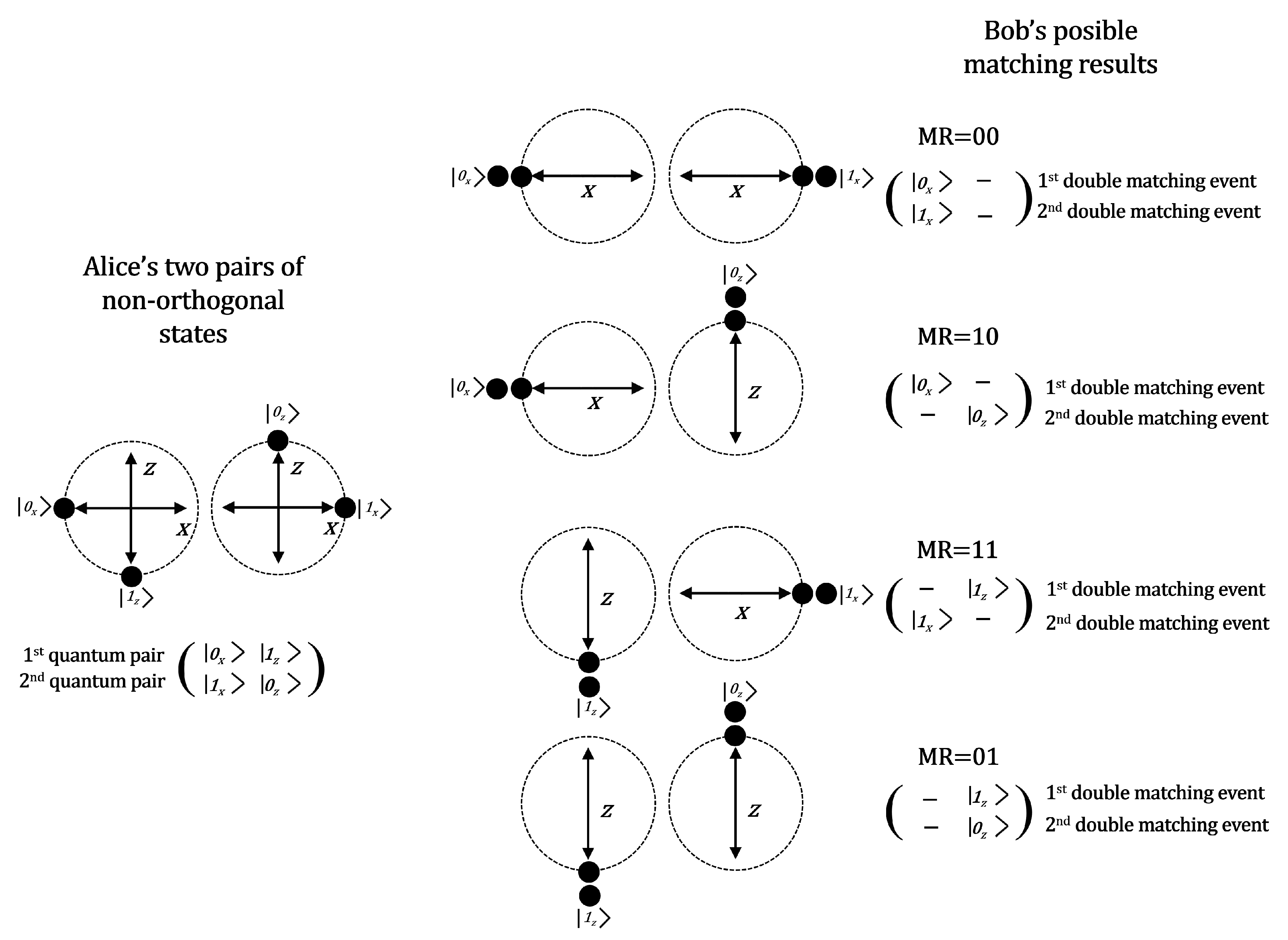
Figure 5.
We see (at left) the states prepared by Alice, two pairs of non-orthogonal states: and . After a double matching detection event is produced at Bob’s side (in this example two double detection events) the possible matching results are exhibited at the right.
Figure 5.
We see (at left) the states prepared by Alice, two pairs of non-orthogonal states: and . After a double matching detection event is produced at Bob’s side (in this example two double detection events) the possible matching results are exhibited at the right.

Figure 6.
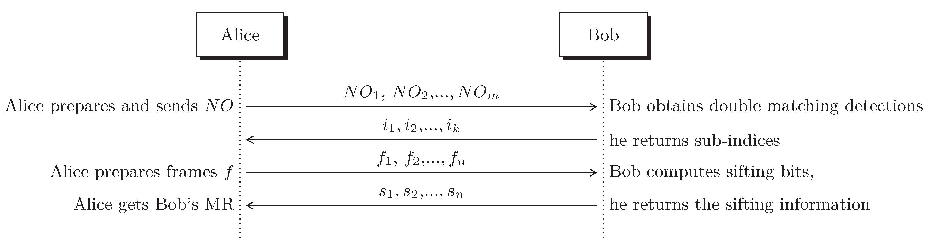
The exchange of messages assuming an error free protocol. represents the pairs of non-orthogonal qubits, the sub-indices k denote the double matching detection events at Bob’s station, f represents the the required information to construct the frames and s denotes the sifting bits computed by Bob.
Figure 6.
The exchange of messages assuming an error free protocol. represents the pairs of non-orthogonal qubits, the sub-indices k denote the double matching detection events at Bob’s station, f represents the the required information to construct the frames and s denotes the sifting bits computed by Bob.

Figure 7.
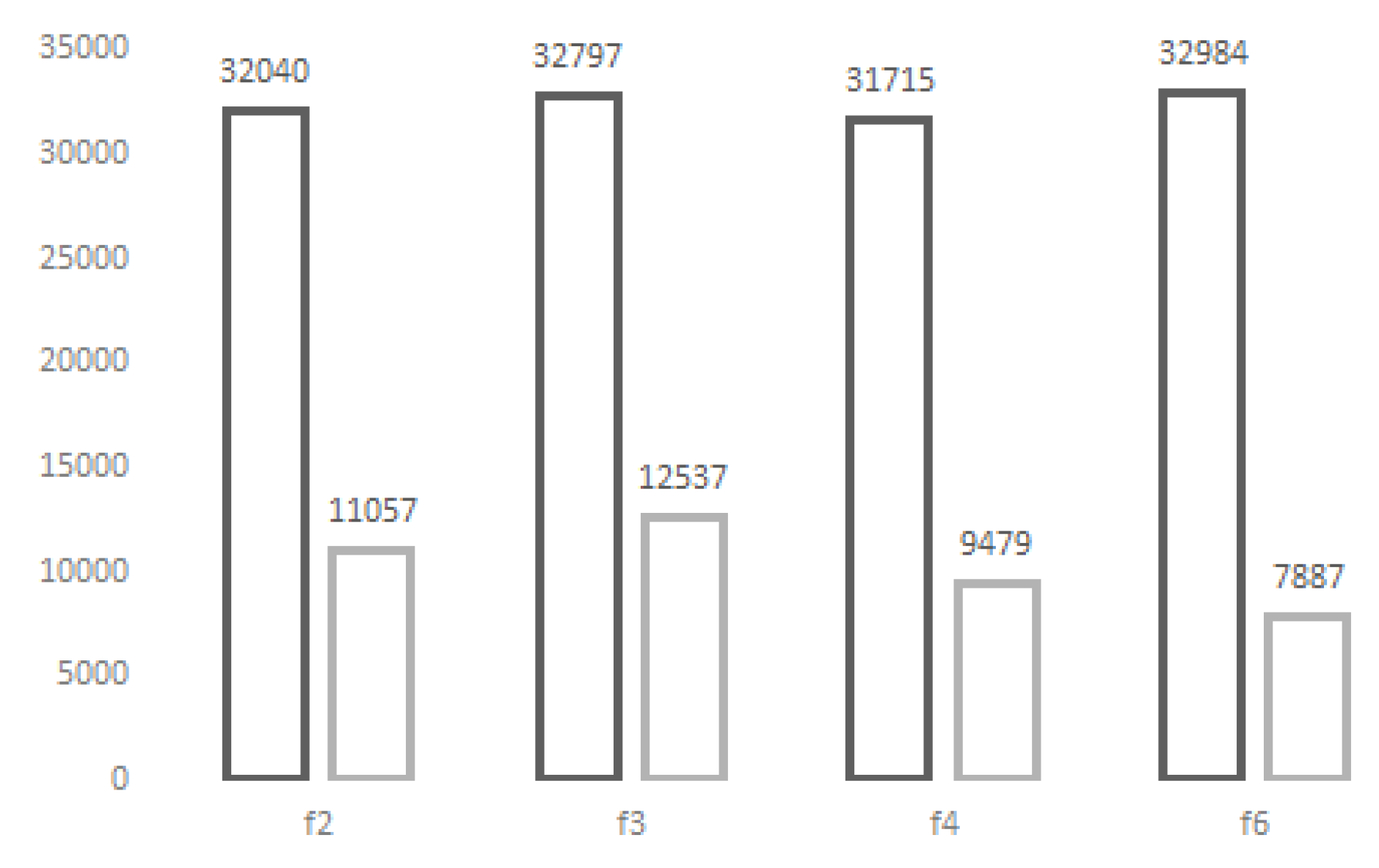
From the experimental simulation in Table 14 we show the frame contribution when QBER = 30%, 605,060 frames have been created and 237,762 correspond to auxiliary frames. For each frame , , and we show the number of frames created (left) and the frames after error correction (right).
Figure 7.
From the experimental simulation in Table 14 we show the frame contribution when QBER = 30%, 605,060 frames have been created and 237,762 correspond to auxiliary frames. For each frame , , and we show the number of frames created (left) and the frames after error correction (right).

Figure 8.
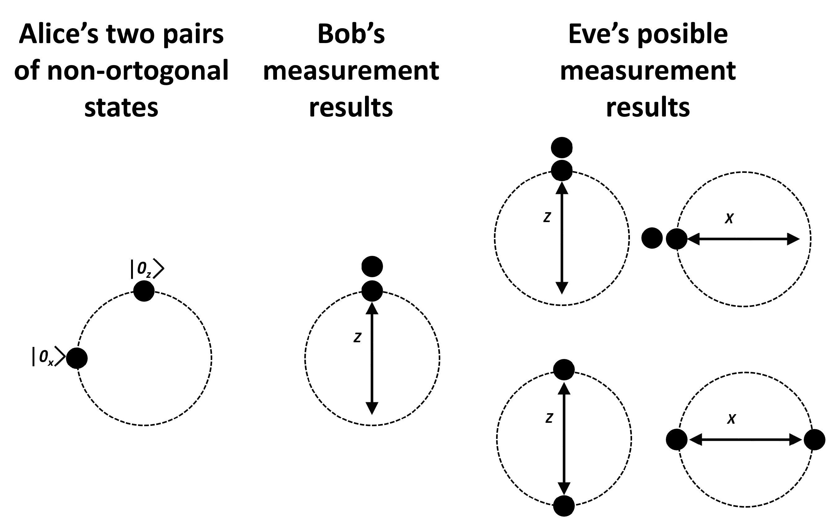
Alice sends a pair of non-orthogonal states to Bob who obtains a double matching detection at his optical detectors. Eve has a copy of such states, however she has a 0.5 chance to choose the correct measurement basis (X or Z). Furthermore, the probability to get a double matching detection event is 0.5. Therefore, Eve’s probability to get Bob’s result is just 0.25.
Figure 8.
Alice sends a pair of non-orthogonal states to Bob who obtains a double matching detection at his optical detectors. Eve has a copy of such states, however she has a 0.5 chance to choose the correct measurement basis (X or Z). Furthermore, the probability to get a double matching detection event is 0.5. Therefore, Eve’s probability to get Bob’s result is just 0.25.

Figure 9.
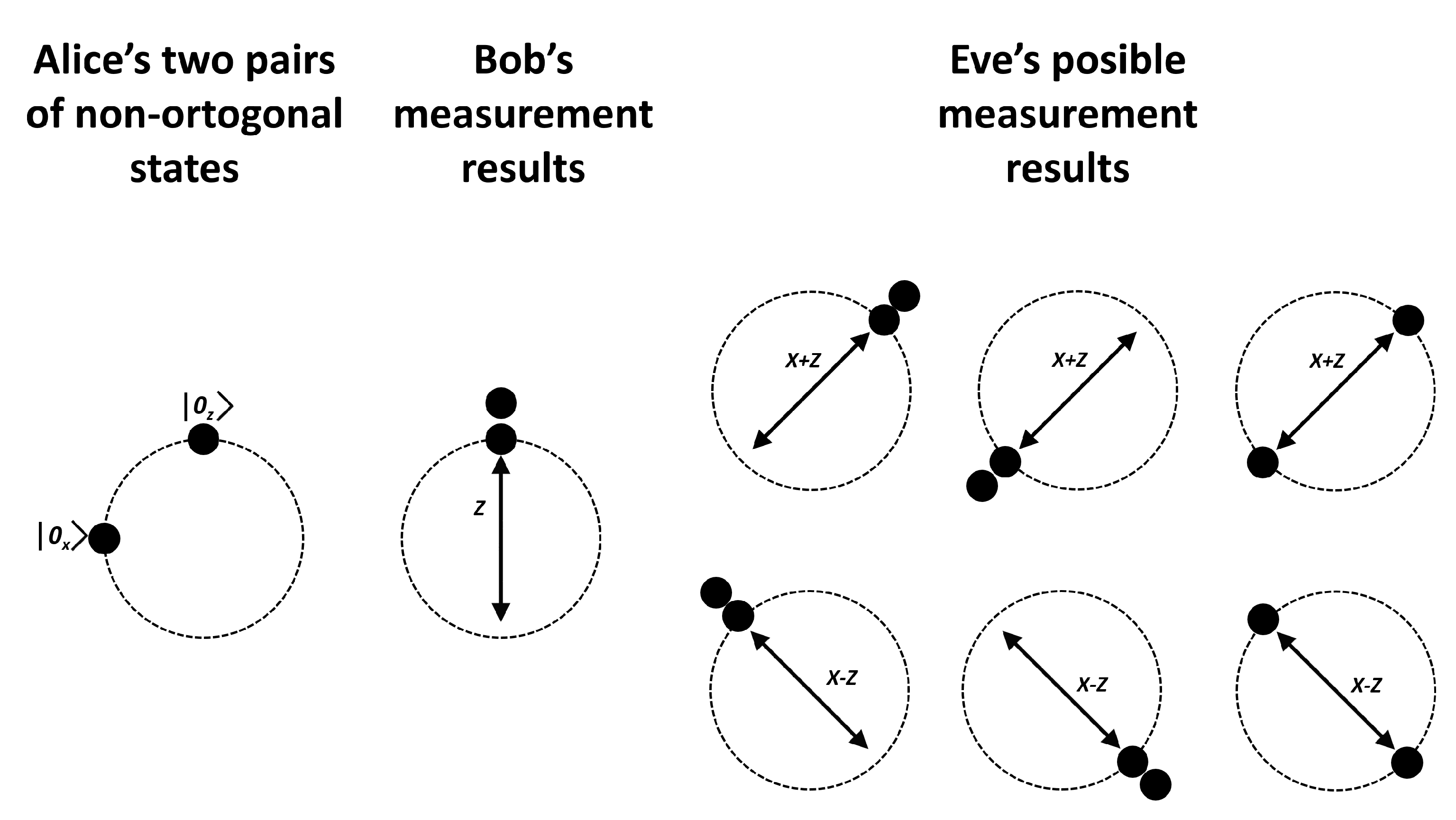
Alice sends a pair of non-orthogonal states to Bob who obtains a double matching detection event at his optical detectors. Eve has a copy of such states, however he has a 0.5 chance to choose the optimal measurement basis, in this case the basis. Despite Eve choose between bases or , the chance to guess Bob’s result is so she obtains an inconclusive result with . From here, the probability for Eve to obtain Bob’s measurement result is 0.28125.
Figure 9.
Alice sends a pair of non-orthogonal states to Bob who obtains a double matching detection event at his optical detectors. Eve has a copy of such states, however he has a 0.5 chance to choose the optimal measurement basis, in this case the basis. Despite Eve choose between bases or , the chance to guess Bob’s result is so she obtains an inconclusive result with . From here, the probability for Eve to obtain Bob’s measurement result is 0.28125.

Table 1.
Comparison of reconciliation methods as presented in [22].
Table 1.
Comparison of reconciliation methods as presented in [22].
| Reconciliation | Method | Advantages | Disadvantages |
|---|---|---|---|
| Interactive | Binary [16] | Easy and simple | Large communication overhead |
| Cascade [17] | Easy and simple | ||
| Strong ability of error correction | |||
| Code based | Winnow [18] | Communication time depending on the rate | Additional errors (Hamming) |
| Great Efficiency | |||
| LDPC [19] | Correction of errors as Cascade | ||
| Improvement of the safety of the protocol |
Table 2.
Measurement results after a double detection event (matching and non-matching). In the matching case, Bob measures the two quantum states with coincident results. Only double matching events encode a bit. The shared bit comes from the compatible measurement.
Table 2.
Measurement results after a double detection event (matching and non-matching). In the matching case, Bob measures the two quantum states with coincident results. Only double matching events encode a bit. The shared bit comes from the compatible measurement.
| Bob’s Basis Measurement | ||||
|---|---|---|---|---|
| Alice’s Non-Orthogonal Pairs | Matching Event | Non-Matching Event | ||
| X | Z | X | Z | |
| (, ) | (, ) | (, ) | (, ) | (, ) |
| (, ) | (, ) | (, ) | (, ) | (, ) |
| (, ) | (, ) | (, ) | (, ) | (, ) |
| (, ) | (, ) | (, ) | (, ) | (, ) |
Table 3.
There are 6 useful frames: , where and 8 useless frames , where .
| Useful Frames | Useless Frames | ||
|---|---|---|---|
Table 4.
There exist four possible Matching Results (MR) for frames. The bit produced by a double matching event is represented inside the ket notation with the symbol •. Additionally, each MR has been identified with a binary code left to each frame. After the sifting process such MR code will become part of the secret key.
| MR=00 | MR=10 |
| MR=01 | MR=11 |
Table 5.
To the left we see the 6 usable frames that Alice can prepare to be sent over the quantum channel. Provided Bob obtains the two (required) Matching Results he computes the sifting bits applying the xor function to each column (they are written at the bottom of each frame). The sifting bits which are publicly announced, conform the set that does not contain redundancy, so that Alice can identify without ambiguity Bob’s Matching Results.
| Alice | Bob | |||
|---|---|---|---|---|
Table 6.
The sifting bits obtained by Bob (written at the bottom of each frame) must be produced from at least two different Matching Results. At the right of each frame we have indicated the corresponding original Alice’s frame.
Table 6.
The sifting bits obtained by Bob (written at the bottom of each frame) must be produced from at least two different Matching Results. At the right of each frame we have indicated the corresponding original Alice’s frame.
Table 7.
The Sifting String (SS) which is publicly announced is constructed with the sifting bits and the measured bits. To achieve a secret bit (sb) each SS must be correlated at least to two Matching Results (MR).
Table 7.
The Sifting String (SS) which is publicly announced is constructed with the sifting bits and the measured bits. To achieve a secret bit (sb) each SS must be correlated at least to two Matching Results (MR).
| SS | MR | Frame | sb | MR | Frame | sb | |
|---|---|---|---|---|---|---|---|
| Sifting | Measured | (See Table 4) | (See Table 3) | (See Table 4) | (See Table 3) | ||
| 00 | 00 | 10 | 0 | 11 | 1 | ||
| 00 | 11 | 00 | 0 | 01 | 1 | ||
| 01 | 10 | 01 | 0 | 11 | 1 | ||
| 01 | 01 | 10 | 0 | 01 | 1 | ||
| 10 | 01 | 00 | 0 | 11 | 1 | ||
| 10 | 10 | 00 | 0 | 10 | 1 | ||
| 11 | 11 | 11 | 0 | 10 | 1 | ||
Table 8.
We list the set of valid Sifting Strings (SS) for each frame . Provided Alice has sent an specific frame to Bob, he returns the SS which must be one of the listed here, otherwise an error is detected. We analyze if an error is detectable when occurs in the 1st (or 2nd) measured bit.
Table 8.
We list the set of valid Sifting Strings (SS) for each frame . Provided Alice has sent an specific frame to Bob, he returns the SS which must be one of the listed here, otherwise an error is detected. We analyze if an error is detectable when occurs in the 1st (or 2nd) measured bit.
| Frame | Valid Sifting Strings (SS) | MR | 1st Bit | Detection | 2nd Bit | Detection | 1st and 2nd Bits | Detection |
|---|---|---|---|---|---|---|---|---|
| SS | 10 | 10,10 | yes | 01,01 | yes | 11,11 | no | |
| SS | 01 | 00,00 | no | 00,11 | yes | 01,01 | yes | |
| SS | 00 | 00,11 | yes | 00,00 | no | 10,10 | yes | |
| SS | 11 | 10,01 | no | 01,10 | no | 00,00 | no | |
| SS | 00 | 10,01 | no | 10,10 | yes | 00,00 | yes | |
| SS | 01 | 00,11 | no | 00,00 | yes | 01,10 | yes | |
| SS | 11 | 11,11 | no | 00,00 | yes | 01,10 | yes | |
| SS | 10 | 01,01 | no | 10,10 | yes | 00,00 | yes | |
| SS | 01 | 01,01 | no | 01,10 | yes | 00,00 | yes | |
| SS | 10 | 11,11 | no | 00,00 | yes | 10,10 | yes | |
| SS | 00 | 00,11 | no | 00,00 | yes | 10,10 | yes | |
| SS | 11 | 10,01 | no | 01,10 | yes | 00,00 | yes | |
| SS | 01 | 01,01 | yes | 01,10 | no | 00,00 | yes | |
| SS | 11 | 00,00 | yes | 11,11 | no | 10,01 | yes | |
| SS | 00 | 00,00 | yes | 00,11 | no | 10,01 | yes | |
| SS | 10 | 01,01 | yes | 10,10 | no | 00,00 | yes | |
| SS | 11 | 01,10 | yes | 10,01 | yes | 11,11 | no | |
| SS | 01 | 00,11 | yes | 00,00 | no | 01,10 | yes | |
| SS | 00 | 00,00 | no | 00,11 | yes | 10,01 | yes | |
| SS | 10 | 01,01 | no | 10,10 | no | 00,00 | no | |
| SS | 00 | 10,01 | yes | 10,10 | no | 00,00 | yes | |
| SS | 01 | 00,00 | yes | 00,11 | no | 01,01 | yes | |
| SS | 10 | 00,00 | yes | 11,11 | no | 01,01 | yes | |
| SS | 11 | 10,01 | yes | 01,10 | no | 00,00 | yes |
Table 9.
Bob measures the quantum pair (), but produces . This error is identified half of the times using . Similarly, Bob receives () but results in . This error is successfully managed half of the times using . The second and fourth rows show the erroneous cases. The errors are represented with bars above the bits: in and in .
| Alice | Bob | |||
|---|---|---|---|---|
Table 10.
Error correction map for undetected errors. From Table 8 we list all erroneous cases that keep undetected. The bit underlined in the ket notation flips into the the bit underlined in the Sifting String. Some errors are identified using the auxiliary frames and . If detection of error is not possible the frame must be removed. For this reason frame is ambiguous and must be removed.
| Frame | Quantum Pair | Sifting String | Detection Frame | Sifting String | Error-Bit | Correction Code |
|---|---|---|---|---|---|---|
| - | - | 1st | remove | |||
| - | - | 2nd | remove | |||
| - | - | 1st | remove | |||
| 01,10 | 1st | SS | ||||
| SS | ||||||
| - | - | 1st | remove | |||
| 10,10 | 1st | SS | ||||
| SS |
Table 11.
Error correction map for undetected errors (cont). Frame is ambiguous and will be discarded.
Table 11.
Error correction map for undetected errors (cont). Frame is ambiguous and will be discarded.
| Frame | Quantum Pair | Sifting String | Detection Frame | Sifting String | Error-Bit | Correction |
|---|---|---|---|---|---|---|
| - | - | 2nd | remove | |||
| 10,10 | 2nd | SS | ||||
| SS | ||||||
| - | - | 1st | remove | |||
| - | - | 2nd | remove | |||
| 01,10 | 2nd | SS | ||||
| SS | ||||||
| - | - | 2nd | remove | |||
Table 12.
We list usable (4) frames, it must be included (4) frames , , and to verify errors by means of the null quantum pairs.
Table 12.
We list usable (4) frames, it must be included (4) frames , , and to verify errors by means of the null quantum pairs.
Table 13.
If an error is detected using or , then Alice corrects the error according to Table 10 and Table 11. If no error is found Alice uses the secret bits listed here.
| SS | MR | Frame | sb | MR | Frame | sb |
|---|---|---|---|---|---|---|
| 00 | 0 | 01 | 1 | |||
| 11 | 0 | 10 | 1 | |||
| 01 | 0 | 11 | 1 | |||
| 10 | 0 | 01 | 1 | |||
| 00 | 0 | 11 | 1 | |||
| 00 | 0 | 10 | 1 |
Table 14.
Simulation of the protocol when have been registered 1000 double matching detection events. Tests were performed in an Intel Core i7-8750H 2.2 GHz, 12GB RAM.
Table 14.
Simulation of the protocol when have been registered 1000 double matching detection events. Tests were performed in an Intel Core i7-8750H 2.2 GHz, 12GB RAM.
| QBER | Time (ms) | Secret Bits | Throughput (Kbps) |
|---|---|---|---|
| 54.0146 | 59,873.7 | 1108.90435 | |
| 57.6022 | 58,911.2 | 1025.13229 | |
| 54.0614 | 52,630.1 | 972.532054 | |
| 55.6709 | 48,830.9 | 877.799205 | |
| 60.9381 | 46,706.4 | 773.520113 | |
| 78.4297 | 40,960.0 | 522.251137 |
© 2020 by the authors. Licensee MDPI, Basel, Switzerland. This article is an open access article distributed under the terms and conditions of the Creative Commons Attribution (CC BY) license (http://creativecommons.org/licenses/by/4.0/).
Share and Cite
MDPI and ACS Style
Lizama-Perez, L.A.; López, J.M. Quantum Key Distillation Using Binary Frames. Symmetry 2020, 12, 1053. https://0-doi-org.brum.beds.ac.uk/10.3390/sym12061053
AMA Style
Lizama-Perez LA, López JM. Quantum Key Distillation Using Binary Frames. Symmetry. 2020; 12(6):1053. https://0-doi-org.brum.beds.ac.uk/10.3390/sym12061053
Chicago/Turabian StyleLizama-Perez, Luis A., and J. Mauricio López. 2020. "Quantum Key Distillation Using Binary Frames" Symmetry 12, no. 6: 1053. https://0-doi-org.brum.beds.ac.uk/10.3390/sym12061053
Note that from the first issue of 2016, this journal uses article numbers instead of page numbers. See further details here.