
The Development of a Heterogeneous MP Data Model Based on the Ontological Approach


Ural Federal University, 620002 Yekaterinburg, Russia
*
Author to whom correspondence should be addressed.
Symmetry 2021, 13(5), 813; https://0-doi-org.brum.beds.ac.uk/10.3390/sym13050813
Submission received: 31 March 2021
/
Revised: 19 April 2021
/
Accepted: 2 May 2021
/
Published: 6 May 2021
(This article belongs to the Special Issue New Advances and Applications in Statistical Quality Control)
Abstract
:The article discusses the approaches providing symmetric access of all industrial production services to the data of business processes of the enterprise by building a single warehouse of heterogeneous data of a metallurgical production. The warehouse is a part of an automated statistic quality control system for the products of a metallurgical enterprise. The article describes an ontological storage model of data coming from various sources of information in the production process. The concept of “a unit of production of metallurgical production” is introduced that is the connecting component of the entire production life cycle of a metallurgical production. The authors propose an ontological model of the production process, in terms of information flows which are formed in an enterprise at each stage of production. Based on the constructed ontological model, the structure of recording an array of information in the heterogeneous data warehouse is justified and formed. Heterogeneous data warehouse forms a single information space of the enterprise, which serves as the basis for analytical analysis throughout the production and decision—making process. For example, timely response to the deviation reasons from the given physical and chemical properties of the finished product.
1. Introduction
Modern economic science states the question to ensure the "symmetry of information variety" [1] where the term ‘symmetric information’ means information that can be accessed equally by any market participants interested in it. For example, until recently, the Central Bank of the Russian Federation informed the public exclusively about those prohibitions that are related to the banks’ non-compliance with the deposit insurance agency system. This situation led to an ‘asymmetry’ of economic information, since it was available only to the bank’s management and/or, in some cases, to the bank’s owners. To eliminate this situation, the Central Bank proposed to inform the public firstly about the introduction of the most noticeable measures against banks, such as the revocation of the licenses and at the second stage - about the introduction of appropriate restrictions [2].
Industrial enterprises have similar problems when they use information systems at various levels. However, the information collected by these systems is now stored in various unrelated databases that significantly complicates the use of the collected technological and management information while solving optimisation problems of the business processes of this production. Thus, there is an asymmetry of the collected information. Consider the solution of this problem in more detail on the example of metallurgical production through the creation of a system of statistical quality control of products of a metallurgical enterprise (MP) and the management of relevant business processes. The MP uses a large number of information systems (IS) that solve narrowly focused tasks for managing the technological process or the enterprise document flow, also, each information system forms its own data sets. Consider typical information systems in a metallurgical enterprise.
Information management systems are aimed at the planning production process and the tracking of orders execution which are under contracts. Such solutions are presented in the following publications [3,4,5]. One category of information system is aimed at the managing of technological processes and the supporting of the production process at each stage of the metallurgical enterprise [4,5,6,7,8]. For example, one manages the blast furnace production, the other controls the supply of gas, charge and other resources, in order to ensure the smooth operation of the blast furnace.
The other category of information system, manufacturing execution systems, are focused providing resources to an enterprise [9]. This includes provision of water, electricity, monitoring of equipment performance and other means of supporting the production process. This class of information system solves the monitoring problems of the production process in terms of continuous performance.
Thus, the set of subject-oriented information systems has led to the appearance of disparate data arrays and the absence of a single information space in one enterprise, which does not allow the making of management decisions based on consolidated data for the entire enterprise.
- The existing approaches include a number of limitations for IS development:
- the structure of the data warehouse (DW) of the IS formed at the stage of information system modeling remains unchanged at the stage of IS operation;
- most IS are subject-oriented (they collect and store information from a specific data source in the given period of their appearance);
- it is impossible to coordinate metadata between different ISs without changing the structure of at least one DW.
The construction of a single information space for an enterprise was proposed to be solved by the integration of information systems [10,11,12,13,14,15,16], but this method is not applicable for a metallurgical enterprise, due to the large variety of data sets with different natures and structures formed by information systems at different stages of the production process.
The concept of building a single information space for a metallurgical enterprise was previously described in [17,18,19,20,21,22], where the architecture of an information system was proposed to automate the production of finished metallurgical products. This information system consists of two subsystems: Automated Information System for Data Collection and Analysis (AIS DCA)—implements the functions of receiving and storing technological information from various sources; Automated Information System for Mathematical Data Processing—optimizes technological, logistics and organizational processes.
This article demonstrates the logic of adopting the warehouse of heterogeneous data (HDW) module, which is included in the AIS DCA. We explain the structure of information storage with an ontological model and further, on the basis of Russian standards for automation production, we offer a description of the infological structure of data recording formation.
The analysis of metallurgical production (MP) features showed that each stage or unit of production in the life cycle of metallurgical production (UP MP), which uses unique equipment, has its own physical and chemical properties leading to the fact that the data on UP MP appear to be heterogeneous. In this regard, a scientifically based choice of the principles for constructing a single HDW for metallurgical production (MP) and the selection of appropriate technological solutions require the development a generalized model of MP data. In turn, it is necessary to justify the basic concepts, and on their basis, describe and systematize the variety of information flows in MP, as well as the relationship between these flows. The modern theory of control systems proposes an ontological approach to solve these problems, and its usage is recommended by GOST R ISO 10 303-11-2009 “The National Standard of the Russian Federation. Systems of automation production and their integration. Data presentation about this product and the exchange of this data” [23].
The given study presents an approach based on the usage of an ontological description of the relationship between components, processes and tuples that determine the infological logic of model building. In accordance with the given approach, the logic of forming HDW is determined at the modeling stage of the data structure, but not the data structures themselves, and the recording structure is formed dynamically at the moment of writing data to HDW.
The article describes the information and ontological models developed for heterogeneous MP data, as well as the universal methodology for the development of WH.
2. Development of Informational Models of the Production Plan, Finished Product, Unit of MP Production
We introduce the terms and definitions used to construct an ontological description of the finished products (GP) of the MP [24,25,26,27,28,29].
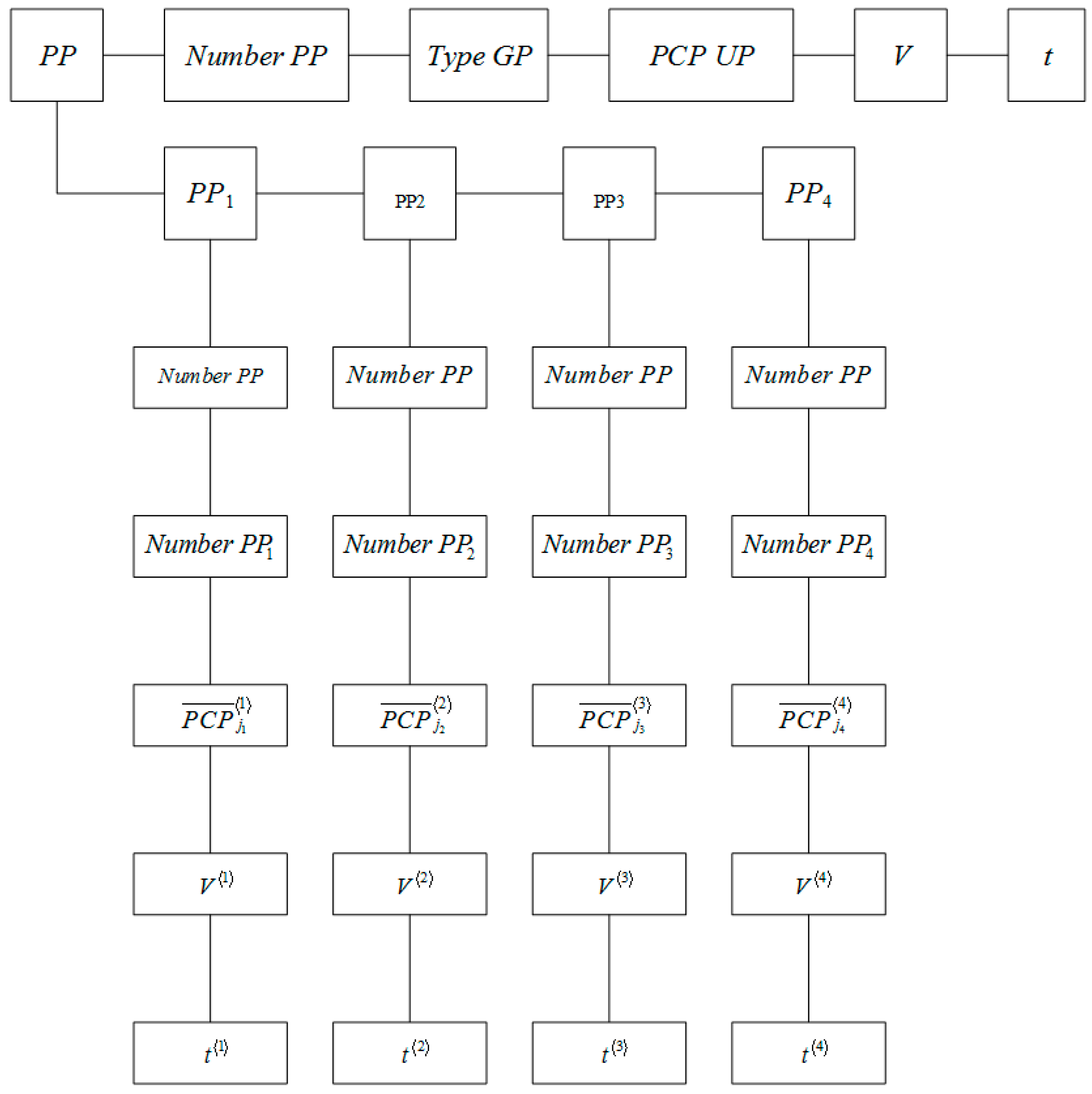
The production plan is supposed to be the document setting the type of GP MP, the number of piece or non-piece units of production UP MP, V, PCP (physical–chemical properties), properties of UP MP—UP, and the time interval when the release of GP MP should be implemented .
Therefore, PP GP (PP—production plan) is a tuple from the informational point of view:
where
- Number PP—unique PP identifier,
- Type GP—GP name (in accordance with the nomenclature of GP MP),
- PCP GP—physical–chemical properties of GP MP,
- V—is the number of piece or non-piece UP of the MP set by the PP;
- —the time interval when the release of the GP MP should be implemented.
The GP MP is a UP set produced during the PP implementation of this process. From the informational point of view, a GP is a tuple. .
Following [30], the UP is “A separate copy of a piece product or a quantity of non-piece or piece products (finished or in the process of manufacturing) determined in accordance with the established procedure”.
The process of manufacturing GP MP is implemented by performing four consecutive stages:
- production preparation;
- blast-furnace production;
- converter production;
- GP production on continuous billet casting machine,
The PP can also be considered as a set of mutually agreed plans at each of the MP stages:
here
where
- Number PP1—identifier of PP release UP1,
- , —PCP variety UP1, ,
- —output volume (in selected units) UP1,
- —time interval when the release was implemented UP1;
- Number PP2—identifier of PP release UP2,
- , —PCP variety UP2, ,
- —output volume (in selected units) UP2,
- —time interval when the release was implemented UP2.
- Number PP3—identifier of PP release UP3,
- , —PCP variety UP3, ,
- —output volume (in selected units) UP3,
- —time interval when the release was implemented UP3,
- Number PP4—identifier of PP release UP4,
- , —PCP variety UP4, ,
- —output volume (in selected units) UP4,
- —the time interval when the release was implemented UP4.
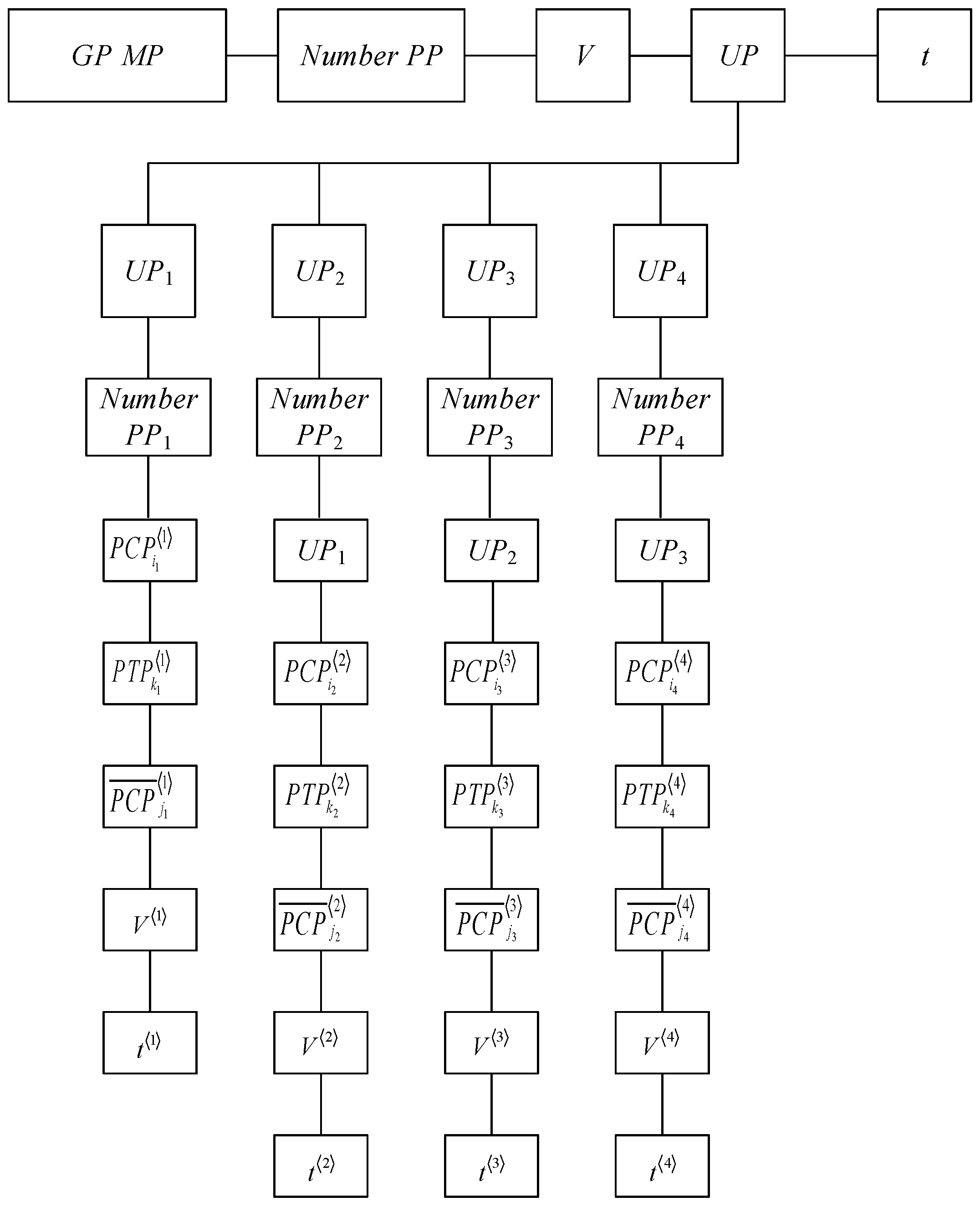
Accordingly, the UP MP is a set of information that characterizes the UP at each MP stages:
here
where
- , —value variety of PCP components used in the production UP1, ,
- , —a set of values of technological process parameters (PTP) implemented for production UP1, ,
- , —PCP variety UP1, ,
- —output volume (in selected units) UP1,
- —time interval when the release was implemented UP1;
- , —value variety of PCP components used in the production UP2, , ,
- , —the set of PTP values implemented for production UP2, ,
- , —PCP variety UP2, ,
- —output volume (in selected units) UP2,
- —time interval when the release was implemented UP2.
- , —the set of PTP values implemented for production UP3, ,
- , —PCP variety UP3, ,
- —output volume (in selected units) UP3,
- —time interval when the release was implemented UP3.
- , , —value variety of PCP components used in the production , ,
- , —the set of PTP values implemented for production , ,
- —output volume (in selected units) ,
- —the time interval when the release was implemented .
The information trees of the PP and GP MP, constructed in accordance with (1)–(6) and (7)–(11), respectively, are shown in Figure 1 and Figure 2.
Figure 1 and Figure 2 show that the selected mathematical description of the MP, and MP and MP UP describes the process of issuing MP GP as a whole unit. Indeed, in accordance with the given PP, which determines the nomenclature, the type of GP MP (GP Type), its PCP (PCP GP) and the number of piece or non-piece UP MP V are set into the GP plan production at the stage of manufacturing GP at stage 4 (PP4), which provides the fulfilment of the following conditions:
- (1)
- the volume of UP4 output is equal to the GP output volume set by the PP:;
- (2)
- with the given accuracy, they correspond to PCP determined in PP:;
- (3)
- The output time of the entire UP4 volume does not exceed the production time of the GP MP set in the PP:.
In addition, such requirements are defined for , and, accordingly, for to ensure that the requirements of 1–3 are met.
Further, based on PP4, PP3 is formed, which sets out the requirements for the volume of output of UP3, , , to ensure that the following 1–3 conditions are met. In addition, such requirements for and, respectively, for are defined to ensure that the requirements of 1–3 are met.
Similarly, taking into account PP3, PP2 is formed, which sets out the requirements for the volume of output of UP2, , , to ensure that the following conditions are met: 1–3. In addition, such requirements are defined for , and, accordingly, for to ensure that the requirements of 1–3 are met.
Further, based on PP2, PP1 is formed, which sets out the requirements for the volume of output of UP1, , , to ensure that the following 1–3 conditions are met. In addition, such requirements are defined to ensure that the requirements of 1–3 are met.
Thus, the relationship between PP1, PP2, PP3, PP4 and PP can be represented as the following system of recursive functions:
correspondingly, UP:
It is shown in (12), (13):
- the information about the PP, GP, MP and UP MP, which, as noted above, is heterogeneous information, has a four-layer structure—four nesting levels;
- information about the PP and UP of the MP, which have the same structure, can be stored in a single information structure.
We take into account that for the i-th division of the MP, the reason of the implementation of the corresponding technological process is a certain event Ei that occurs during the release of the UPi (for example, the entry of the UPi−1 from the previous division, the return of the UPi products due to a defect per one of the previous divisions, etc.) and is fixed by the corresponding IP, caused by the source of the event Ei.
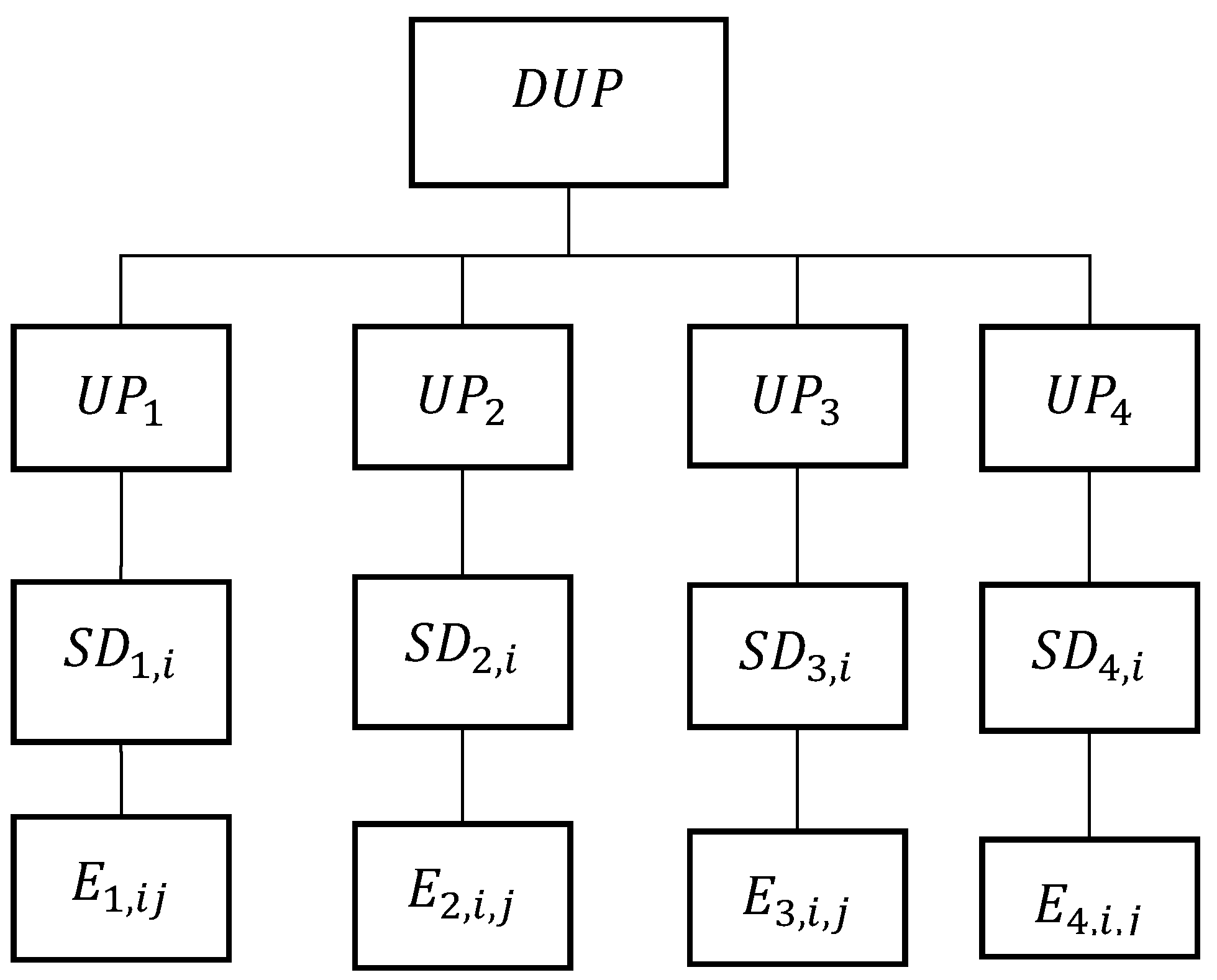
The described features of the information structures that characterize the production process of GP MP conclude that the HDW structure, along with the information structures described above, should provide storage of information represented by the triplet “event (E), UP, source data (SD)”:
which describes the “dynamics” of the (DUP) UPi.
In turn, an event can have a complex structure, depending on the type of event, since there are events that require the attention of MP specialists (managers, technologists, etc.), which are called “incidents”. An incident is characterized by:
- the date and time of occurrence;
- the type of incident (a formal definition of the observed deviation, implemented as a reference to the reference book);
- the link to UP (UP set associated with the given incident);
- the parameter by which the incident was recorded;
- the severity level (on a five-point scale);
- the reason (a formalized text from the directory of reasons, implemented as a reference to the directory).
The sources of incidents are:
- The data verification systems that identify anomalies in the collected data due to emerging technical and/or organizational problems. For example, incidents are recorded when the data obtained about the MP contradicts common sense. This source implements a wide range of checks of the system input data, from null values in the required UP attributes to incorrect numbers of the UP, etc.
- The systems of monitoring technologies. Technology control incidents are recorded when any standardized parameter of any UP does not fit into the regulatory boundaries.
- The system for statistical control of technological processes that record incidents, for example, using Shewhart maps.
- the MP staff, in cases of making certain wrong decisions at any MP stage.
Information about the incident is recorded in the “Incident Log”, which describes the entire life cycle of the incident from its appearance to closure. Each entry log is either a change in some property of the incident (status, responsibility, etc.), or a text comment made by the user. For each entry log, the date, time and the author of the change are stored. Deleting and editing old records via the user interface is not provided.
The DUP information tree is shown in Figure 3.
Thus, the structure of GP MP information, placed in a single HDW, is determined by the structures of the PP, UP, DUP, which, as is seen in Figure 1, Figure 2 and Figure 3, are interrelated with each other.
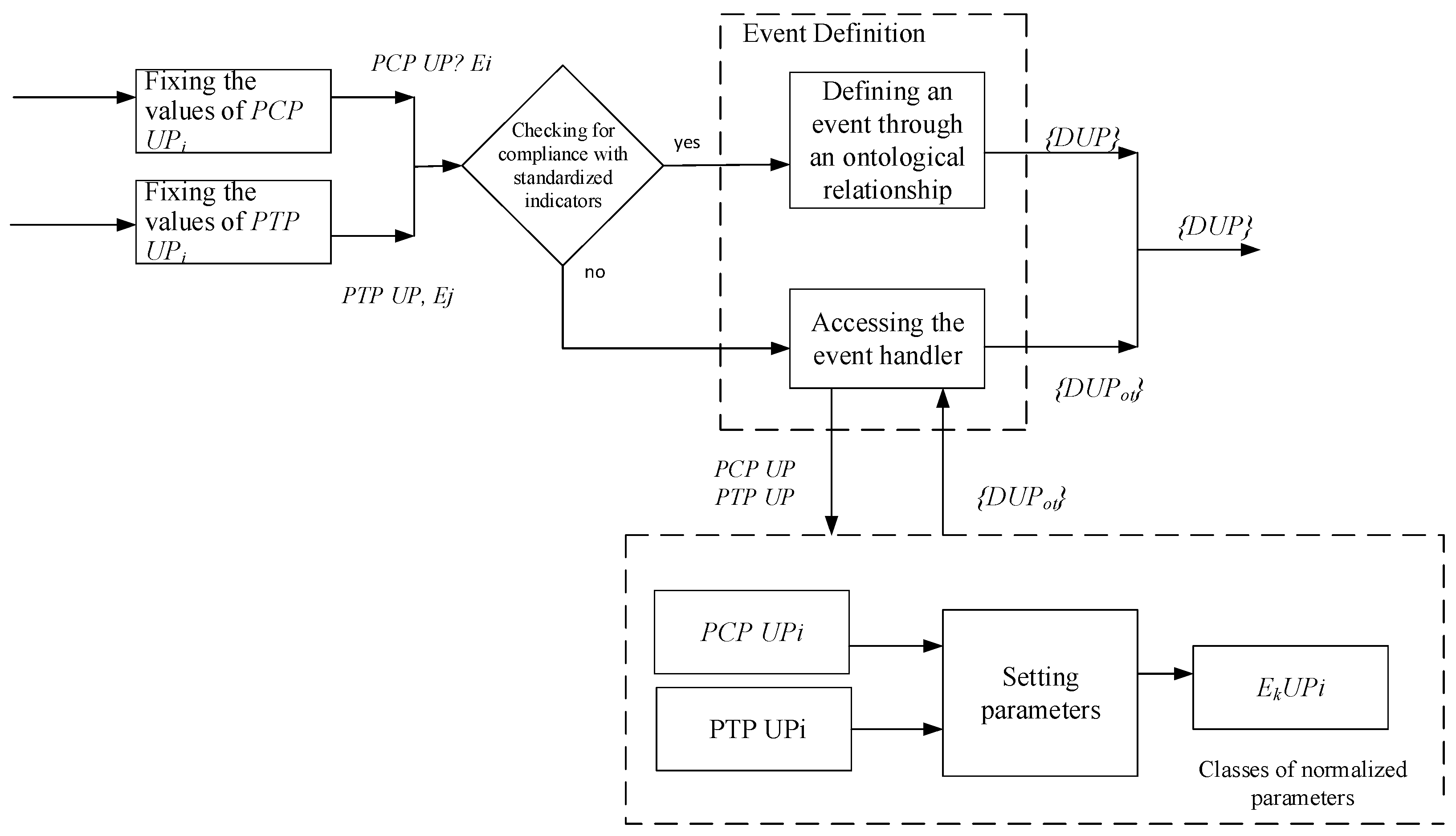
In this regard, it is necessary to develop an ontological model of PP, UP, DUP and, on this basis, ae GP MP ontological model, which takes into account the interrelationships of the heterogeneous information models of MP (Figure 4).
When constructing a UP ontological model, it is taken into account that the obtained values of PCP and PTP UP parameters at the i-stage are checked to correspond to the standardized values and are associated with the event handler {PCP UPi, GPi}, {PTP UPi, SDi}. Event processing is determined by the rules of the ontological description: if the values obtained from the i-th division correspond to or do not exceed the allowed tolerance for this parameter, then a storage structure is formed for the received event {DUPn}. Cases when the obtained parameter values do not correspond to the normalized values or exceed the permissible deviations are recorded by the company’s specialists and are determined as incidents. These events are recorded as {DUPot} and the data is also recorded in the HDW MP for the analysis of the deviation at this stage of production.
3. Development of Ontological Models of the Production Plan, Finished Product, Unit of MP Production
3.1. Components of the Ontological Model
Under the UPi component, we can understand the list of all types of UP MP. Each MP UP contains information about all the parameters that characterize the MP UP of this type (for example, the number of the route map, the number of the operating card, etc., as well as the type of UP: melting, slab, strip, sheet, roll, etc.).
Under the MP UP attribute, we can understand the data related to the MP UP as a whole. Attributes are usually scalar values, since a single attribute value is defined for a given UP. For example, during cast iron melting these repeatedly appear in the same aggregates. However, in practice, some cases have deviations from the current standards, for example, from melting to melting the gas consumption for purging of the converter may change. As a result, the value of this indicator is unique for each UP [31,32].
Moreover, there may be situations in which the attributes have a dimension greater than one. This depends on the particular UP and on the definition of the relevant information request. For example, the average winding temperature of a hot-rolled roll is a scalar for g/k roll, but for a hot-rolled one-and-a-half roll (a roll made up of two rolls rolled independently of each other) the given parameter is a vector containing the temperature values for every roll.
Thus, the data placed in a single HDW MP has a heterogeneous structure that changes over time. In this regard, it is necessary to choose HDW management technologies that provide a dynamic change in the structure of the HDW MP, while maintaining the availability of previously placed data. This method involves the possibility of the dynamic (i.e., during the operation of the system after its launch) addition of sources and parameters, as well as dynamic creation of tables for storing heterogeneous data, for example, PTP with a potentially large number of columns.
Using this approach, a description of the data structure is stored along with the data. This approach has the following advantages. On the one hand, data is collected in tables allowing data blocks to be quickly saved without analysis. On the other hand, the description of the table structure makes it possible to further transform heterogeneous data, for example, analyzing blocks and presenting information for analysis in a “vertical” form. In addition, the structure description can be used when extracting samples, etc. The analysis of data blocks is ensured by identifier columns (for example, the UP number, time, metallurgical length, parameter ID, etc.) which are given in the table, besides columns for parameter storing.
The PCP component of UP MP presents different parameters, namely specified, measured and calculated parameters.
PCP UP at this MP stage is determined at the beginning of the implementation of the corresponding technological process of the MP t-start, further on after its completion at the time t-finish.
Note that there is static information that rarely changes (for example, materials, steel grades, chemical elements, and the relationship between them by the ratio (composition of steel grades)). In this regard, it is advisable to use reference books to store this information.
The observed values of the UP MP parameters are compared with the data in the reference book “Normalization Rules”, which defines the following types of rules: greater than min, less than max, from min to max. Next, according to the reference book “Rationing rule step”, the applicability of this rule is checked.
The list of all possible operands of the rule (identifiers and parameters of the description of the UP MP) is placed in the reference book “Operand of the normalization rule”. As a rule, the parameters of the UP description (the numbers of route and operational maps, the thickness of sheets, etc.) and some collected parameters are used as operands of the normalization rule.
Under the PTP component, we can understand the set of values of the MP technological process indicators which were achieved during the UP production. Frequently, the information on this component is signals-data linked not only to the UP, but also to the time or metallurgical length (for example, the speed of rotation of the lower working roll in the draft stand No. 2). From the informational point of view, signals are vectors of arbitrary dimension. In some situations, a signal is a sequence of argument–value pairs. However, in some cases, the values of the PTP components are scalar values (for example, the metallurgical length in LPC-2), which are linked to the values of the metallurgical length (for example, “temperature and UP at the end of rolling”). The information related to this component of the PTP is a block of data collected at the corresponding stage of the MP with the automated process control system in real time.
Due to the fact that all the data created by the information source must be linked to the source UP ID (for example, at the level of the workshop database, all the data must eventually be linked to the ID in the workshop database), it is necessary to establish a correspondence between the local ID of the information source UP and the ID of the UP of all other sources of information about this MP UP. Next is the process of linking the identifiers of the global and “local” identifiers of the UP.
The following example illustrates the process of linking identifiers. When the event “Processing of a new UP has started” (received from an adjacent unit, the automation of the unit itself, etc.) occurs, the software of the unit requests the external ID of the UP and (or) the number of the UP from the adjacent system. For example, it can be the UP identifier that is the first in the queue for this aggregate. If the external identifier is successfully received, the aggregate software establishes the identifier matching of the IDs. If the external UP identifier could not be obtained, the aggregate software assigns all parameters only to the local ID. Subsequently, on the basis of events data from the UP in the aggregate, and information about queues to the aggregate, an attempt is made to set the correspondence “local ID-external ID” (by the aggregate software itself or the corresponding UPC application). Therefore, to implement the process of linking identifiers, it is necessary to use a “dictionary” which describes:
- data sources;
- tables that store parameters about UP;
- UP parameters;
- UP groups;
- UP identifiers;
- events and transformations with UP;
- standardized parameters;
- reference books necessary for the operation of the information system.
It is advisable to provide the rights to fill in this “dictionary” to the administrator of the HDW MP, who determines the table structures used for data placement about the UP MP, and, if necessary, modifies them, as well as the administrator responsible for the accuracy of the entered information. Further, the content of the “dictionary” is transmitted to the workshop level using the replication. It is necessary to note that this approach avoids a large number of redundant tables, as it enables the use of unique UP identifiers.
Under the component V, we present the volume of UP production (depending on the production stage, the volume is measured in tons, rolls, or pieces).
Under the component t, we present the fixed time points of the events of the UP MP production process (the beginning and end of the technological process at this stage). This information is the identifier of the data, when it is written to the data in the HDW.
GP PP determines, on the basis of concluded contracts for the supply of GP MP, the range of possible values of their parameters and the terms of their production.
Under the DUP component, we present the relationship between events that occur during UP production, recorded in the incident log (the date and time of the incident, the incident type, the author, i.e., the user who created the incident), which then tracks the entire chain of subsequent actions to eliminate them.
3.2. Description of the HDW MP Entity Model
When constructing an ontology, the heterogeneous data storage model is defined in accordance with GOST R ISO 10 303-11-2009 “The National Standard of the Russian Federation. Automation systems of production and their integration. The presentation of data on this product and the exchange of this data” [33,34,35]. In this paper, we are guided by Part 11 “Methods of description. A reference guide to the “EXPRESS” language of the standard”, which regulates the methodology of products’ description throughout their life cycle. The EXPRESS language is the language designed to describe information within a dynamically changing structure during the product lifecycle, based on specifications. Here, the data scheme is the basis for structuring and interconnecting the elements of the product data representation. The EXPRESS language defines logical objects that can be used to set properties, the scope of acceptable values, and imposes certain restrictions. Graphical notations of EXPRESS T language constructs, called EXPRESS-G. B Edraw [18], are introduced in the ISO 10303-1 standard. For practical use, the Express-G Diagram software tool has been created.
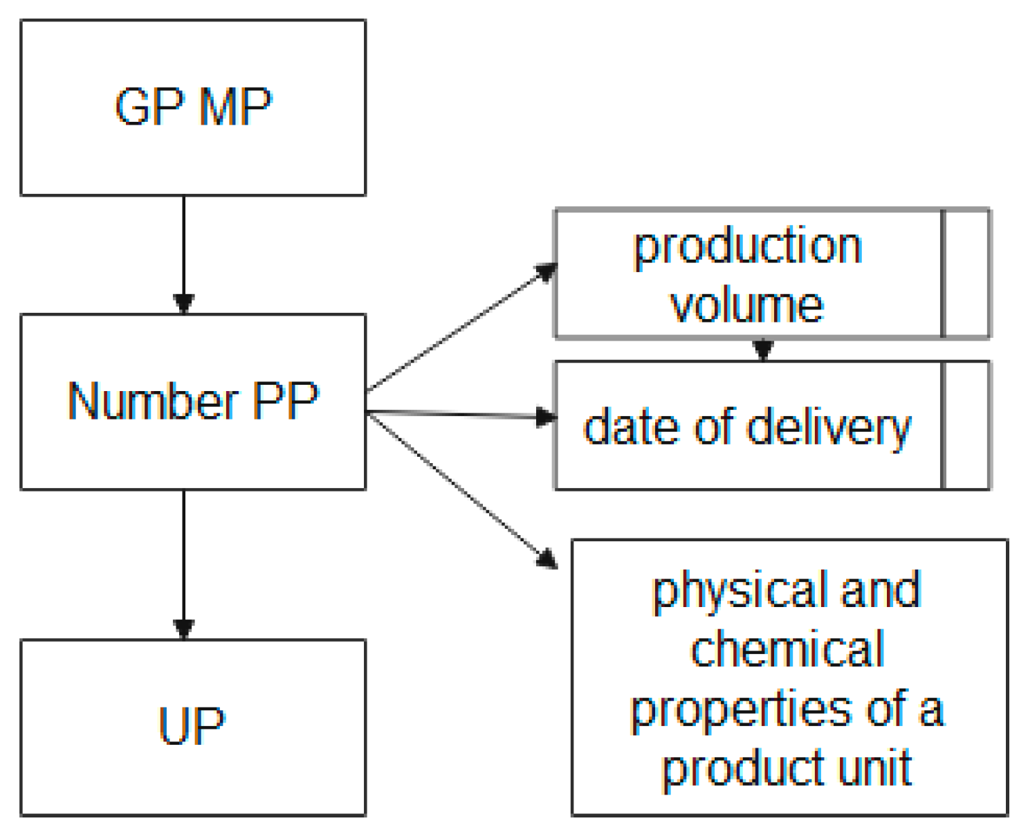
Due to the fact that the basic element is the UP, it is necessary to describe the structural relationship of the UP MP entities. The block diagram of the “GP MP” entity in the EXPRESS-G graphical representation language is shown in Figure 5.
Figure 5 shows that the “GP MP” entity, which stores the name, nomenclature code, measurement units, etc. at the attribute level, is associated with the “PP Number” and “UP” entities.
The entity “PP Number”, the number of the production plan formed on the basis of concluded contracts for the product range, has attributes containing information about the type and volume of the ordered UP, the terms of their production, and the PCP of the UP. This attribute is a regulatory indicator for monitoring the implementation of contracts.
The “UP” entity is the connecting entity between various block diagrams.
The description of the block diagram of the entity “GP MP”, shown in Figure 5, in the EXPRESS language has the form:
| SCHEMA GP MP; |
| ENTITY GP MP; |
| END_ENTITY; |
| ENTITY Number PP |
| SUBTYPE OF (GP MP); |
| Output volume; |
| Delivery date; |
| END_ENTITY; |
| ENTITY PCP UP; |
| END_ENTITY; |
| ENTITY UP; |
| SUBTYPE OF (GP MP); |
| END_ENTITY; |
| END_SCHEMA; |
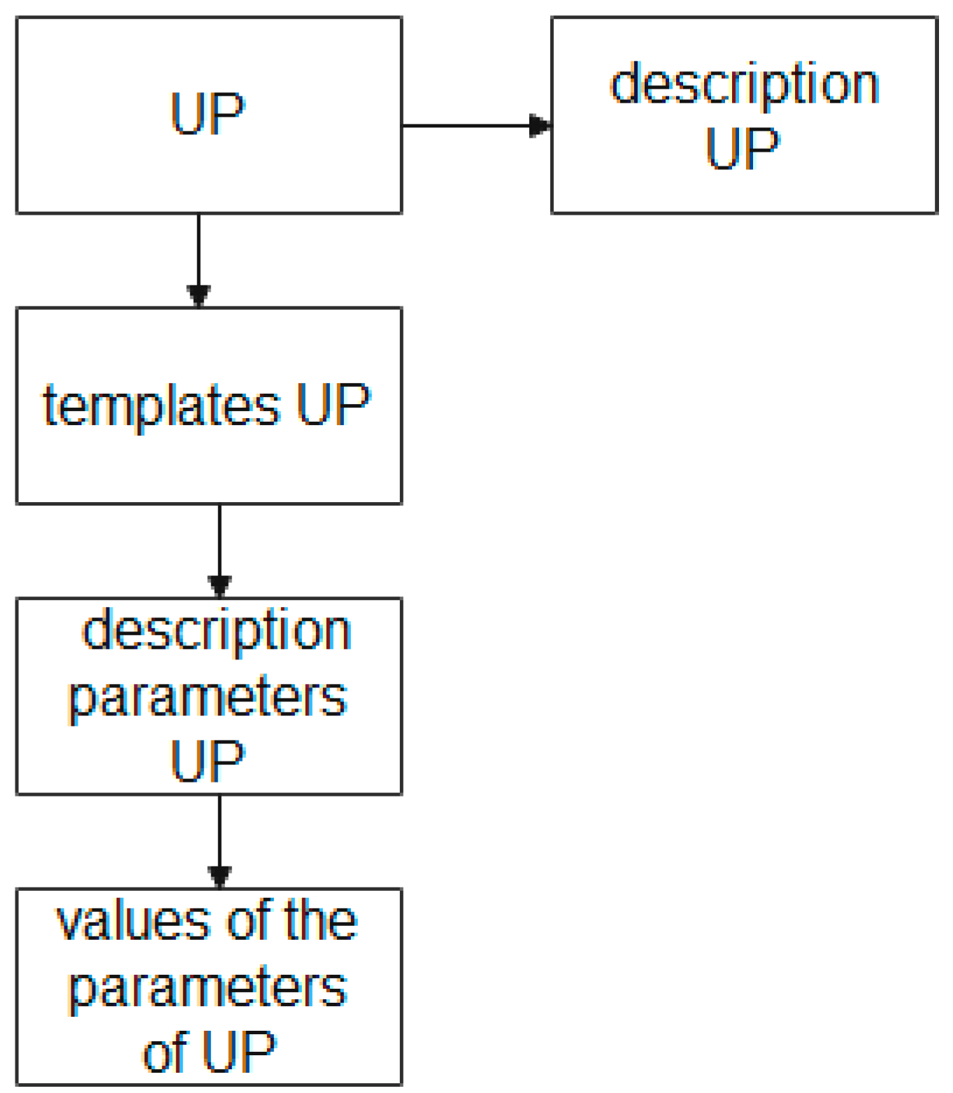
The block diagram of the “UP” entity in the EXPRESS-G graphical representation language is shown in Figure 6.
Figure 6 shows that the entity “UP”, which stores the description of the UP at the attribute level, is associated with the entities “UP template”, “parameters of the description of the UP”, and “values of the UP parameters”. Here, the entity “UP template” allows the creation and storage of layouts of the UP description for different production stages; the entity “UP description parameters”, at each stage, is to set its own template and store the parameters regulated by the specification of this UP; the entity “UP parameter values” provides storage of the parameter values according to the specification given by the UP.
The description of the block diagram of the “UP” entity, shown in Figure 6, in the EXPRESS language has the following form:
| SCHEMA description_UP; |
| ENTITY UP; |
| END_ENTITY; |
| ENTITY UP description |
| SUBTYPE OF (UP); |
| END_ENTITY; |
| ENTITY template_UP |
| SUBTYPE OF (UP); |
| END_ENTITY; |
| ENTITY PARAMETER_UP |
| SUBTYPE OF (template_UP); |
| END_ENTITY; |
| ENTITY value_UP |
| SUBTYPE OF (template_UP); |
| END_ENTITY; |
| END_SCHEMA; |
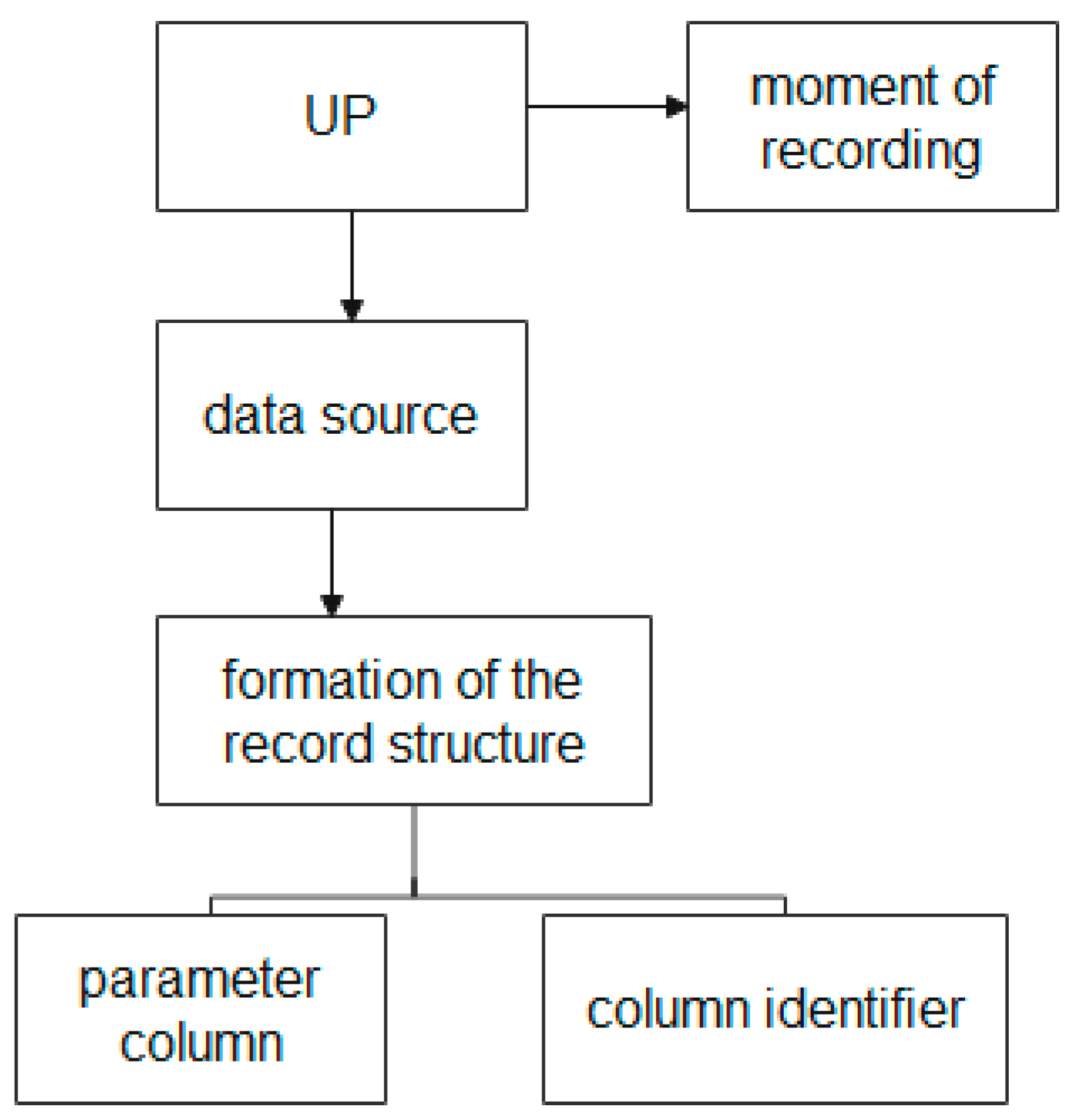
The block diagram of the entities used to form the UP structure in the EXPRESS-G graphical representation language is shown in Figure 7.
Figure 7 shows that the process of forming the UP structure is described using the following entities: the “UP” entity, the “moment of recording” entity, the “data source” entity, the “formation of the record structure” entity, the “parameter column” entity, and the “identifier column” entity.
The “moment of recording” entity provides storage of the date and time of events that occur during the production process of the GP MP, which allows the linking of the data to the corresponding moment of the life cycle of the UP at various production stages.
The “data source” entity provides the collection of data about the sources of information on each of the divisions of the MP. (Recall, the source of information can be an information system, a node, an aggregate, or information from a user at the workshop level.)
The “formation of the record structure” entity, which attributes depending on the source of information and has different structures and rate of data accumulation, provides the use of tables with a dynamically changing structure of attributes and data types.
The “parameter column” and “column identifier” entities provide storage and access to heterogeneous MP data.
The description of the block diagram of the entity “UP”, shown in Figure 7, in the EXPRESS language has the following form:
| SCHEMA formation_UP; |
| ENTITY UP; |
| END_ENTITY; |
| ENTITY moment_records_UP; |
| SUBTYPE OF (UP); |
| END_ENTITY; |
| ENTITY Data source_UP |
| SUBTYPE OF (UP); |
| END_ENTITY; |
| ENTITY forming the record_UP structure |
| SUBTYPE OF (UP); |
| END_ENTITY; |
| ENTITY column_parameter |
| SUBTYPE OF (forming the structure of the notation_UP); |
| END_ENTITY; |
| ENTITY column_identifier |
| SUBTYPE OF (forming the structure of the notation_UP); |
| END_ENTITY; |
| END_SCHEMA; |
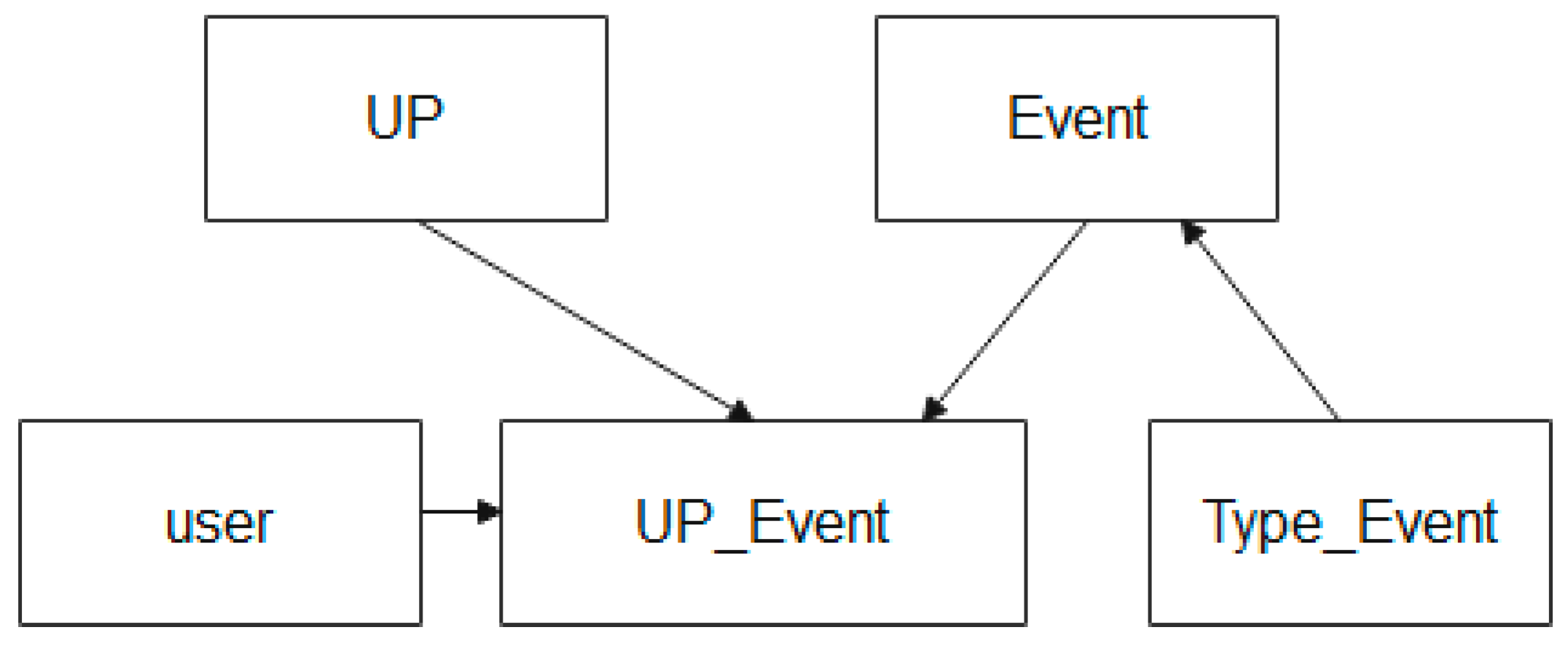
The scheme of entities that are used in the description of the process of storing information about events during the UP MP life cycle in the EXPRESS-G language is shown in Figure 8.
Figure 8 shows that the entity relationship scheme used to describe the process of storing data about events that occur during the UP lifecycle is described using the following entities: the “event” entity, the “user” entity, and the “event type” entity.
The “event” entity provides the creation and storage of control points of the production process, where recorded information about the UP of the MP is created (for example, the start of production of a batch of products, the end of production of a batch of products, deviation by a parameter of the production process, and other facts).
The “role” entity provides a record of the level where the event is recorded, and who it was recorded by.
The Event Type entity provides event categorization.
The description of the block diagram of entities used to describe the process of storing data about events that occur during the life cycle of the UP, shown in Figure 8, in the EXPRESS language has the form:
| SCHEMA Event_UP; |
| ENTITY UP; |
| END_ENTITY; |
| ENTITY Event; |
| END_ENTITY; |
| ENTITY Event_UP |
| SUBTYPE OF (UP, Event); |
| END_ENTITY; |
| ENTITY type_Event |
| END_ENTITY; |
| ENTITY user |
| END_ENTITY; |
| END_SCHEMA; |
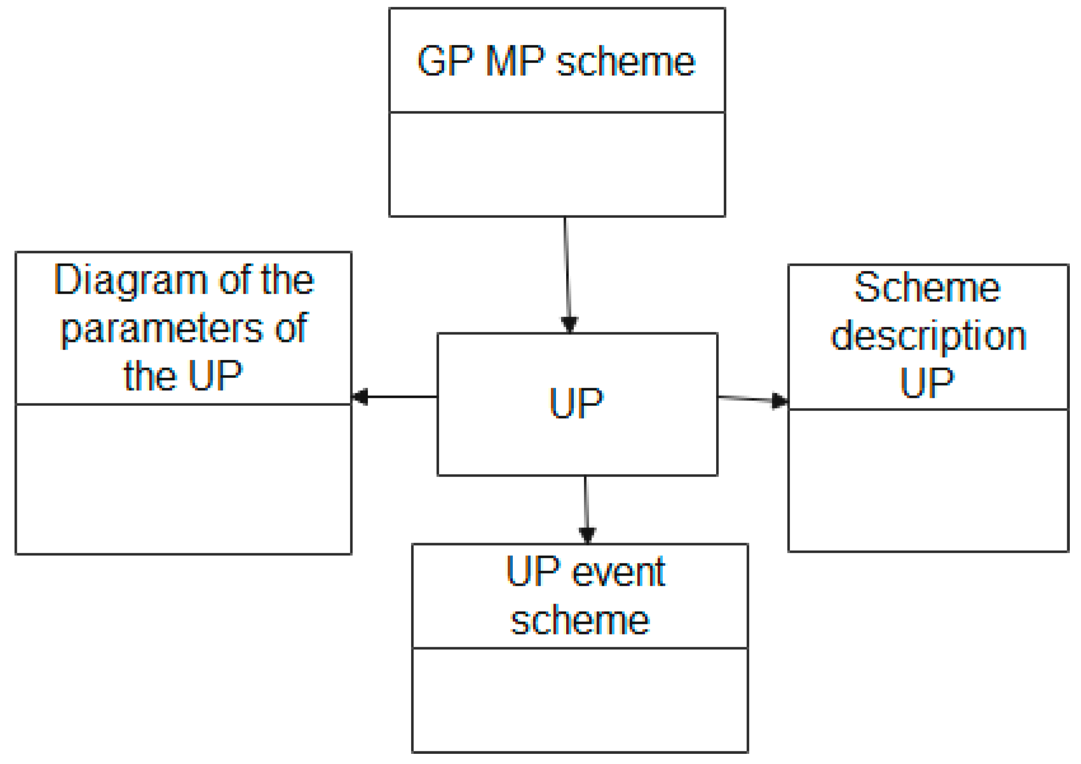
The scheme of entities that are used in the description of the process of storing information about events during the UP MP life cycle in the EXPRESS-G language is shown in Figure 9.
The description of the entities block diagram which is used to describe the UP attribute scheme, shown in Figure 9, in the EXPRESS language has the following form:
| SCHEMA connection_scheme_UP; |
| ENTITY UP; |
| END_ENTITY; |
| SCHEMA GP MP; |
| END_SCHEMA; |
| SCHEMA Scheme UP parameters; |
| END_SCHEMA; |
| SCHEMA Scheme UP description; |
| END_SCHEMA; |
| SCHEMA Schemes of UP event; |
| END_SCHEMA; |
| END_SCHEMA; |
The constructed ontological model of GP MP allows making a reasonable conclusion that the entity “GP MP” includes the following classes of entities (Table 1):
The use of given entities, as will be shown in the next section, provides scientific rationale for a single HDW MP logical structure, which provides storage and access to the following heterogeneous information:
- information about data sources;
- information about UP parameters and methods to group them;
- information about identifiers;
- information about UP description;
- information about UP events and transformations;
- information about UP groups;
- information about standardized parameters;
- information about the system subjects;
- information about the actions with system subjects;
- information about the linking of UP identifiers;
- background information.
Thus, ontological modeling provides the formation of an entity model of the data collected at various stages of the UP MP life cycle and describes the relationships between the data blocks used for the analysis of production processes, in order to identify the causes of defects and optimize the MP business processes.
3.3. Construction Methodology of HDW
The methodology described above for the construction of HDW MP, as eseen from its description, can be used in the structure development of HDW not only for MP, but for any selected GP production. Indeed, regardless of the specific production, the introduced concepts of UP, PP, and GP are universal and can be used to describe the information flows of any selected production which uses a sequential multi-stage technology.
Therefore, while designing and developing HDW fore the selected production, it is recommended to use the following methodology.
- Definition of the structure. PP construction of information models, finished product, units of production for the selected production.
- Construction of heterogeneous data ontology for the selected production.
- Development in accordance with GOST R ISO 10 303-11-2009 of the infological model of HDW for the selected production, based on the infological models of UP, PP, GP.
4. Results
This article presents the research results of building an ontological model of a heterogeneous data warehouse for multistage metallurgical production. The data structure is substantiated, which is formed at the time of recording an array of information from existing automated information systems in the production process.
- In relation to the MP, the structure of information modules “Production plan”, “Unit of production”, and “Finished products” are defined and the corresponding information models are constructed.
- The choice of components set for the ontological model of heterogeneous MP data is justified.
- The ontology of heterogeneous MP data has been developed.
- In accordance with GOST R ISO 10 303-11-2009, an infological model of HDW MP was developed, which was based on the ontological model of heterogeneous data, storing this data with a time-varying structure in dynamically formed tables.
The article is limited to the ontological aspect of building a heterogeneous data warehouse and the infological description of entities. This heterogeneous data warehouse is the part of the information system for supporting the production of finished products in the metallurgical enterprise. The discussed system is at the stage of testing of all components and the overall performance of the system. The future research is supposed to be conducted on the results of current investigation. This heterogeneous data warehouse is the part of the information system for product statistic quality control in a metallurgical enterprise, which solves the issue of ensuring users symmetrical access to a single information resource.
Author Contributions
Conceptualization, S.P., A.B. and O.P.; methodology, S.P. and O.P.; software, S.M. and A.B.; validation, S.M.; formal analysis, A.B.; writing—original draft preparation, S.P., O.C. and O.P.; writing—review and editing, O.P., O.C. and S.P.; visualization, S.M. and A.B.; project administration, O.P.; and funding acquisition, S.P., A.B. and O.P. All authors have read and agreed to the published version of the manuscript.
Funding
The research was funded by the Russian Foundation for Basic Research No. 19-37-90049\19 of 08/27/2019.
Institutional Review Board Statement
Not applicable.
Informed Consent Statement
Not applicable.
Conflicts of Interest
The authors declare no conflict of interest.
References
- Melnikov, V.A. Symmetry of Economic Information. Visualization of the Structure of Economic ‘Space-Time’. Int. Res. J. 2020. Available online: https://cyberleninka.ru/article/n/simmetriya-ekonomicheskoy-informatsii-vizualizatsiya-struktury-ekonomicheskogo-prostranstva-vremeni (accessed on 26 April 2021).
- Igor Zubkov. The Central Bank will Publish Data on Prohibitions for Banks to Attract Deposits. Russian Newspaper. Russian Newspaper Editorial Body. 1 April 2020. Available online: https://rg.ru/2020/04/01/cb-budet-publikovat-dannye-o-zapretah-bankam-na-privlechenie-vkladov.html (accessed on 26 April 2021).
- Automation of Internal Document Flow. Available online: https://burg.abt.ru/company/ (accessed on 20 December 2020).
- Overview of Electronic Document Management Systems. Available online: https://www.ixbt.com/soft/sed.shtml/ (accessed on 20 December 2020).
- SAP Business One. Solution for Automation of Production Enterprises. Available online: https://www.SimpleSAP.ru/ (accessed on 20 December 2020).
- Lavrov, V.V.; Spirin, N.A.; Burykin, A.A.; Shchipanov, K.A.; Rybolovlev, V.Y. Development of the cam system software at blast furnace plant. Metallurg 2015, 58, 703. [Google Scholar] [CrossRef] [Green Version]
- Lavrov, V.V.; Spirin, N.A.; Gurin, N.A.; Rybolovlev, I.A.; Yu, V.; Krasnobaev, A.V. Modern methodology and computer technologies for creating software of model systems supporting decision-making in metallurgy (on the example of blast-furnace production). Metallurg 2017, 60, 679–685. [Google Scholar] [CrossRef] [Green Version]
- Gurin, I.A.; Spirin, N.A.; Lavrov, V.V. Optimal Distribution of Iron Ore Raw Materials in Blast Furnace System. In Proceedings of the 2019 International Russian Automation Conference (RusAutoCon), Sochi, Russia, 5–7 September 2019; pp. 1–5. [Google Scholar] [CrossRef]
- Rybolovlev, V.Y.; Krasnobaev, A.V.; Spirin, N.A.; Lavrov, V.V. Principles of the Development and Introduction of an Automated Process Control System for Blast-Furnace Smelting at the Magnitogorsk Metallurgical Combine. Metallurgist 2015, 59, 653–658. [Google Scholar] [CrossRef]
- Lavrov, V.V.; Spirin, N.A.; Gurin, I.A. Regression Testing of Information-Modeling Systems for Solving Technological Problems in Blast-Furnace Production. In Proceedings of the 2018 International Russian Automation Conference (RusAutoCon), Sochi, Russia, 9–16 September 2018; pp. 1–5. [Google Scholar] [CrossRef]
- Andreev, E.B.; Kutsevich, I.V.; Kutsevich, N.A. MES-Systems. An Inside Look; RTSoft-Cosmoscope: Moscow, Russia, 2015. [Google Scholar]
- Wirth., N. Algorithms and Data Structures; Publishing House: Moscow, Russia, 2000; 384p. [Google Scholar]
- Chernyak, L. Data Integration: Syntax and Semantics; Open Systems; №10; Springer Science+Business Media B.V., Formerly Kluwer Academic Publishers B.V.: Moscow, Russia, 2009. [Google Scholar]
- Kalinichenko, L.A. Metody i Sredstva Integratsii Neodnorodnykh Baz Dannykh; Nauka: Moscow, Russia, 1983; 424p. (In Russian) [Google Scholar]
- Huimin, Z.; Sudha, R. Entity identification for heterogeneous database integration—A multiple classifier system approach and empirical evaluation. Inf. Syst. 2005, 30, 119–132. [Google Scholar] [CrossRef]
- Ventrone, V.; Heiler, S. Some Practical Advice for Dealing with Semantic Heterogeneity in Federated Database Systems. Available online: http://citeseerx.ist.psu.edu/viewdoc/summary?doi=10.1.1.39.3831 (accessed on 29 February 2021).
- e Silva, G.B.; Romano, B.L.; de Campos, H.F.; Vieira, R.G.; da Cunha, A.M.; Dias, L.A.V. Integrating Amazonic Heterogeneous Hydrometeorological Databases. In Proceedings of the 2009 Sixth International Conference on Information Technology: New Generations, Las Vegas, NV, USA, 27–29 April 2009; pp. 119–124. [Google Scholar] [CrossRef]
- Beneventano, D.; Bergamaschi, S. The MOMIS Methodology for Integrating Heterogeneous Data Sources, Building the Information Society, Building the Information Society; Springer: Boston, MA, USA, 2004; pp. 19–24. [Google Scholar]
- Porshnev, S.; Borodin, A.; Kovaleva, A.; Ponomareva, O. The Concept of Automated System of Steel Production Storage Data Structure. In Proceedings of the 2018 International Conference on Applied Mathematics & Computational Science (ICAMCS.NET), Budapest, Hungary, 6–8 October 2018; pp. 19–193. [Google Scholar] [CrossRef]
- Ponomareva, O.; Porshnev, S.; Borodin, A.; Mirvoda, S. Date preparation module of automated metallurgical products production system. In Proceedings of the IOP 3rd International Conference on Advanced Technologies in Aerospace, Mechanical and Automation Engineering, MIST: Aerospace 2020, Krasnoyarsk, Russia, 20–21 November 2021; Volume 1047, p. 012003. [Google Scholar] [CrossRef]
- Porshnev, S.; Ponomareva, O.; Borodin, A.; Mirvoda, S. Automated system of production of metallurgical products: From different databases to creation of a unified data storage. Autom. Modern Technol. 2018, 72, 435–440. [Google Scholar]
- Porshnev, S.; Ponomareva, O.; Trofimov, S.; Anchugova, O. A Mathematical Model for the Description of Metallurgical Production on the Basis of Heterogeneous Data. In Proceedings of the 2020 Ural Symposium on Biomedical Engineering, Radioelectronics and Information Technology (USBEREIT), Yekaterinburg, Russia, 7 May 2020; pp. 496–498. [Google Scholar] [CrossRef]
- Aksyonov, K.; Antonova, A.; Sysoletin, E. Comparative Analysis of Subcontracting Scheduling Methods. In Progress in Computing, Analytics and Networking; Pattnaik, P.K., Rautaray, S.S., Das, H., Nayak, J., Eds.; Springer: Singapore, 2018; Volume 710, pp. 439–448. [Google Scholar]
- Sysoletin, E.G.; Aksyonov, K.A.; Nisskhen, X.D.; Aksyonova, O.P. Development of Components of Multi-agent CASE-System for Describing the Logic of Behavior of Mobile Robots. In Proceedings of the 2017 European Modelling Symposium (EMS), Manchester, UK, 12 November 2017; pp. 3–8. [Google Scholar] [CrossRef]
- National Standard of the Russian Federation. Quality of Data. Part 100. Basic data. Data Exchange of Characteristics. Data Quality. Part 100. Master Data. Exchange of Characteristic Data. Overview. Available online: https://www.tc184-sc4.org (accessed on 20 December 2020).
- Staab, S.; Studer, R. Handbook on Ontologies; Springer: Berlin/Heidelberg, Germany, 2003; p. 656. [Google Scholar] [CrossRef]
- Maedche, A.; Motik, B.; Stojanovic, L.; Studer, R.; Volz, R. Ontologies for Enterprise Knowledge Management. IEEE Intell. Syst. 2003, 18. [Google Scholar] [CrossRef] [Green Version]
- Kleschev, A.S. Mathematical models of domain ontologies. Part of the existing approaches to the definition of the concept of “ontology”, mathematical models of ontologies. Int. J. Inf. Theor. Appl. 2007, 14, 35–43. [Google Scholar]
- Borgest, N.M. Ontology of design. In Theoretical Basis; Electronic Textbook/N. M. Borgest; Electronic text and graphic data (3Mb); The Ministry of Education and Science of the Russian Federation, Samara State Aerospace University: Samara, Russia, 2011; p. 77. [Google Scholar]
- Uspensky, M.B. Development and Research of Methods and Models for Processing Diagnostic Information for the Detection and Localization of Faults in Data Storage Systems. Peter the Velikogo st. Petersburg Polytechnical University, St. Petersburg. 2020. Available online: https://www.spbstu.ru/upload/postgraduate/dsb/296581-thesis.pdf (accessed on 20 December 2020).
- Where Do Ontologies Begin? Available online: https://habr.com/ru/post/140696/ (accessed on 20 December 2020).
- Mechanical Engineering. Explanatory Dictionary of Terms. Available online: http://sl3d.ru/slovar/e/1128-edinica-produkcii.html (accessed on 20 December 2020).
- Spirin, N.; Lavrov, V. Information Systems in Metallurgy; Lecture notes; Ural State Technical University-UPI: Yekaterinburg, Russia, 2004. [Google Scholar]
- “Industrial Automation Systems and Their Integration. Submission of Product Data and Exchange Of This Data. Part 11. Methods of Description. Language Reference Guide EXPRESS Industrial Automation Systems and Integration. Product Data Representation and Exchange. Part 11. Description Methods. The EXPRESS Language Reference Manual”. National Standard of the Russian Federation. 2010. Available online: http://docs.cntd.ru/document/1200082100 (accessed on 20 December 2020).
- Edraw Software. Type Computer Program. Available online: https://www.edrawsoft.com (accessed on 20 December 2020).
Figure 1.
PP Information Tree.

Figure 2.
GP MP Information Tree.

Figure 3.
The DUP Information tree.

Figure 4.
Diagram of the relationship between parameters and events in the HDW MP.

Figure 5.
Block diagram of the “GP MP” entity.

Figure 6.
UP description scheme.

Figure 7.
Diagram of the entities used to form the UP structure.

Figure 8.
Scheme of entity relationships used to describe the process of storing data about events that occur during the UP lifecycle.
Figure 8.
Scheme of entity relationships used to describe the process of storing data about events that occur during the UP lifecycle.

Figure 9.
The scheme of entity relationships used to describe UP attribute schemes.


Table 1.
Properties of data schemes and entity classes for the construction the HDW UP MP.
| Name of the Data Scheme or Entity Class | Explanation |
|---|---|
| Data scheme “GP MP” | Combining information that is generated in ERP systems, based on concluded contracts and PP, into a scheme of entity classes |
| Entity class “GP MP”; | Contains information about the company’s product range |
| Entity class “PP number” | Contains information about the volume output of the specified nomenclature, the date of delivery under the contract, and the required physical and chemical properties of the declared products. It is a subclass of the GP MP entity |
| Entity class “UP” | Contains the product unit identifier, which will allow indexing data about this product throughout the entire life cycle. In the given solution, it is the binding class. |
| Data scheme “formation_UP” | Data combination of entities that present details of UP information |
| Entity class “template_UP” | Contains the reference to the reference book which is the basis of the UP template. The entity class “template_UP” is a subclass of the entity “UP” |
| Entity class “parameter_UP” | Contains data about parameters that correspond to the UP specification. The entity class “Parameter_UP” is a subclass of the entity “Template_UP” |
| Entity Class “value_UP” | Contains data about allowed values of the UP parameters. The entity class “value_UP” is a subclass of the entity “template_UP” |
| Data scheme “formation_UP” | Combination of the data entities into the scheme that collects information from various production information systems about the production of the given UP sample |
| Entity class “UP” | Previously formed entity class “UP” combines data from the production IS and indexes the resulting data sets. |
| Entity class “moment_recording_UP” | Information about the date and time of receiving data from other IS recorded |
| Entity Class “forming a record_structure_UP” | This class allows the dynamic formation of the data structure, depending on the parameters passed and their values for this instance of the UP |
| Entity class “moment_recording_UP” | Contains data about the UP of the specified parameter, which is transmitted from various production ICS throughout the entire life cycle of the UP. The class of the entity “column_parameter” is a subclass of the entity “structures_records_UP” |
| Entity class “column_identifier” | Contains the values of the current UP parameter, which are transmitted from various production ICS throughout the entire life cycle of the UP. This can be data of various types: integer values, fractional values, signals, blocks of binary data, or clusters of non-structured data. The entity class “id_column” is a subclass of the entity “ structures_record “.» |
| Data scheme “formation_UP” | Combining entities that collect information about the events of the UP production cycle into a data scheme. |
| Entity class “UP” | The connecting entity “UP”, including for determining events about the UP |
| Entity Class “Event” | Records an event appearance about the UP. Events are phases of the production cycle, incidents, accidents, and other facts. |
| Entity class “type_Event” | The event is classified by the type and the level of response to an event. |
| Entity Class “Role” | Contains information about the one who records the event and the user’s identification in the system. |
| Data scheme “total_UP” | The combination of data schemes into data scheme described earlier are combined through the “UP” entity, where there is accumulated heterogeneous information over the entire UP life cycle for further analysis and query generation. |
Publisher’s Note: MDPI stays neutral with regard to jurisdictional claims in published maps and institutional affiliations. |
© 2021 by the authors. Licensee MDPI, Basel, Switzerland. This article is an open access article distributed under the terms and conditions of the Creative Commons Attribution (CC BY) license (https://creativecommons.org/licenses/by/4.0/).
Share and Cite
MDPI and ACS Style
Porshnev, S.; Borodin, A.; Ponomareva, O.; Mirvoda, S.; Chernova, O. The Development of a Heterogeneous MP Data Model Based on the Ontological Approach. Symmetry 2021, 13, 813. https://0-doi-org.brum.beds.ac.uk/10.3390/sym13050813
AMA Style
Porshnev S, Borodin A, Ponomareva O, Mirvoda S, Chernova O. The Development of a Heterogeneous MP Data Model Based on the Ontological Approach. Symmetry. 2021; 13(5):813. https://0-doi-org.brum.beds.ac.uk/10.3390/sym13050813
Chicago/Turabian StylePorshnev, Sergey, Andrey Borodin, Olga Ponomareva, Sergey Mirvoda, and Olga Chernova. 2021. "The Development of a Heterogeneous MP Data Model Based on the Ontological Approach" Symmetry 13, no. 5: 813. https://0-doi-org.brum.beds.ac.uk/10.3390/sym13050813
Note that from the first issue of 2016, this journal uses article numbers instead of page numbers. See further details here.