
The Limits of Fine Particle Ultrasonic Coagulation


Biysk Technological Institute (Branch), Altay State Technical University, Trofimova, 27, 659305 Biysk, Russia
*
Authors to whom correspondence should be addressed.
Symmetry 2021, 13(9), 1607; https://0-doi-org.brum.beds.ac.uk/10.3390/sym13091607
Submission received: 13 July 2021
/
Revised: 24 August 2021
/
Accepted: 25 August 2021
/
Published: 1 September 2021
(This article belongs to the Special Issue Dispersed Systems: Physics, Optics, Invariants, Symmetry)
Abstract
:This paper describes the studies conducted in order to identify the limits of ultrasonic exposure’s effect on the fine particle coagulation process. It has been established as a result of the studies that ultrasonic exposure with a sound pressure level of 160 dB is capable of ensuring coagulation of particles sized 2.5 µm with efficiency δ = 83%. An increase of the coagulation up to 13% is induced with generation of swirling flows. The suggested approach to increasing the coagulation efficiency owing to vortex-type flows between the radiating and reflecting surfaces ensures efficiency of coagulation δ = 96 %. The implementation of this approach has shown that with generation of vortex-type acoustic flows, it makes the most sense for a concentration of particles of 18×10−3 g/m3. Incremental efficiency at such concentrations amounts to 50%.
1. Introduction
The separation of solid or liquid particles from gaseous medium not only enables gas treatment, but also presents an opportunity of further use of the captured valuable materials. This process is implemented in gaseous media due to the interaction of dispersed particles with each other and is referred to as coagulation.
The coagulation mechanism consists in bringing together the particles suspended in the gas until they come into contact and aggregate. The convergence of particles can be caused by a variety of reasons (Brownian motion, the presence of a velocity gradient in a moving medium, flow turbulization, electrical interaction of particles, hydrodynamic interaction, etc.). The coagulation has different names according to these reasons: Brownian [1], gradient [2], coagulation in a turbulent flow [3], etc.
The effect of ultrasonic oscillations on gaseous media makes it possible to increase the efficiency of any types of coagulation due to the fact that the particles contained in gaseous medium are driven to an oscillatory mode of motion, as a result of which they collide more often and become enlarged much faster than without ultrasonic exposure [4,5,6].
In 1931, for the first time, an increase of the efficiency of coagulation was observed owing to ultrasonic exposure of the smoke particles during experiments [7].
Since then, numerous theoretical and experimental studies have been carried out under various conditions, which have made it possible to establish the possibilities of coagulation of particles of various sizes, properties, and speed of motion, depending on the power of ultrasonic exposure, oscillation frequency, and duration and conditions of exposure. These studies have focused on identification of the mechanisms of ultrasonic coagulation and determination of the modes of effective exposure. In this way, it was established that the efficiency of coagulation is proportional to the square of the amplitude of ultrasonic oscillations, and showed that the introduction of additional liquid particles (increase in moisture) can improve the process of aggregation of the solid particles [8,9]. It was found that oscillations with an acoustic pressure intensity of 130–140 dB can effectively influence the aggregation of fine particles. As regards the influence of oscillation frequency, sound with a frequency of 1000–1800 Hz has been effectively used. It was found that ultrafine fog droplets rapidly coagulated when exposed to oscillations with a frequency of 6000 Hz at a sound intensity of 148 dB [10,11,12].
At the same time, it is obvious nowadays that the main condition enabling coagulation of particles is the impact of ultrasonic oscillations (safe for humans, animals, and the environment) at frequencies above 20 kHz, with a sound pressure level of at least 130–135 dB and implementation of such an impact on the dust-laden gas flow for a certain time necessary and sufficient for the particles to aggregate to a size sufficient for their subsequent capture. For example, with an equal level of ultrasonic pressure (145 dB), exposure to ultrasonic oscillations for 2.8–3.6 s provides a 65% degree of coagulation of particles with a size of 5 µm, and with an increase in the exposure time from 14 to 21 s, it increases from 70% to 95% [7,8,9,10,11,12,13,14].
It should also be noted that a necessary condition for effective ultrasonic coagulation is a certain volumetric concentration of particles in a gaseous medium, sufficient for the required number of collisions between particles. Roughly, the volumetric concentration of dust particles with a size of 1–10 µm in a gas medium should be at least 1–5 g/m3. A lower volumetric concentration is required for smaller dust particles than for large ones, since the number of small particles at the same dust content of the gas will be larger. To increase the concentration of interacting particles, additional neutral aerosol (usually water) is injected [15,16,17,18].
A unique distinguishing feature of ultrasonic coagulation is the ability to precipitate highly dispersed aerosols (less than 2.5 µm), the capture of which with standard equipment is associated with significant difficulties, and is sometimes just impossible. This is due to the fact that the involvement of particles in the oscillatory motion caused by the effect of oscillations largely depends on the mass of the particles, and with intense oscillatory motion, the probability of collision and aggregation of fine particles into aggregates increases.
Studies of the regularities of the ultrasonic coagulation process of particles of different natures and sizes dedicated to identification of the optimum modes of implementation of the process and in different conditions have been conducted by many authors recently. The results of these studies form the basis of numerous industrial installations created for new industries and for the production of new materials.
However, ultrasonic coagulation has not yet become properly commercialized as a solution of the practical problems faced by modern industries, especially those related to the capture of fine particles, for the following reasons [15,16,17,18,19]:
- There is no methodology for selecting the most effective modes of ultrasonic exposure based on the strength of sound pressure, frequency, generated local pressure drops in the gas environment, etc.
- Lack of data regarding the effect of coagulation conditions, which would make it possible to recommend the best conditions for ultrasonic exposure in terms of the time, shape, and size of exposed zones, speed, flow patterns, etc.
- Lack of objective data on the limiting capabilities of ultrasonic exposure in various conditions of propagation and exposure to oscillations (continuous or discontinuous, with or without resonance amplification, when changing the size of flows and the pattern of their vortices from the sizes of coagulators to sizes corresponding to the pressure drop zones in the oscillatory process).
- There are no sources of ultrasonic exposure capable of providing the maximum efficiency effect on the coagulation process (by the sound pressure level), optimized in frequency and allowing generation of local pressure drops of various shapes and values in local areas during the required exposure time.
This article summarizes the approaches proposed by the authors to solve the listed problems. The principles of the construction of new devices for the implementation of the approaches proposed by the authors are also described. This will make it possible to create new methods of coagulation and ensure their practical implementation. Therefore, the objectives of the presented work are:
- -
- The development of new methods of practical implementation of the most effective modes (in terms of sound pressure, frequency, shape of the oscillatory process) and conditions of ultrasonic exposure, for the subsequent design and application of coagulation devices;
- -
- The development of special devices enabling ultrasonic exposure at maximum sound intensity, at the maximum efficiency frequency, allowing generation of maximum pressure drops in local areas of exposure, to form conditions for the necessary and sufficient time of exposure on the flows generated.
To achieve this goal, the article considers two modes of ultrasonic exposure: symmetric, in the mode of a plane standing wave formed by a piston emitter; and asymmetric, created by a bending-vibrating disc radiator. The acoustic flows arising during the formation of an asymmetric acoustic field and their influence on the efficiency of ultrasonic coagulation are considered.
A detailed approach to meeting the outlined objectives is presented below.
2. Determining the Limits of Ultrasonic Exposure’s Impact on the Coagulation Process
The ultrasonic exposure limits during coagulation of fine-dispersed particles (2.5 µm and less) have not been experimentally determined so far. This does not allow the implementation of practical designs of ultrasonic coagulators with maximum efficiency and, most importantly, does not make it possible to identify ways to solve the problem of further increasing the efficiency of ultrasonic coagulation of particles with a size of 2.5 µm and less.
In this regard, it becomes relevant to conduct research to identify the limiting capabilities of ultrasonic exposure.
Obviously, ultrasonic exposure with a sound power of 160 dB (intensity 1 W/cm2) should become necessary and sufficient. Exposure to greater sound power will not only generate a coagulating effect, but will also destroy the aggregations (conglomerates) of particles or simply spray liquid particles [20,21,22].
A decision was made to use the particles of a calibrated size created by means of a special purpose device, a Topas ATM 226 compressor generator with an adjustable aerosol flow volume, as the coagulated particles. The Topas ATM 226 generator ensures generation of aerosol with dispersed characteristics that remain steady over time: size of the formed particles in the range of 0.1–2.5 µm and a volume content of up to 108 particles/cm3. Such known aerosol liquid as DEHS is used as the spray liquid.
The efficiency of coagulation was determined as the ratio of the initial concentration of aerosol at the entrance to the experimental setup to the concentration of aerosol at the exit from the setup. Coagulation efficiency was calculated using the following formula:
where Coutput and Cinput are the measured values of the volumetric concentration of aerosol at the outlet and inlet of the installation, respectively [23,24,25].
To ensure the maximum effect of ultrasonic exposure, the mode of resonant amplification of oscillations in the coagulation chamber can be implemented using a round metal reflector. To ensure resonance modes and setting different ultrasonic pressure levels, an option of adjusting the distance between the radiator and the reflector by moving the radiator along the vertical axis of the coagulation chamber must be provided [25,26].
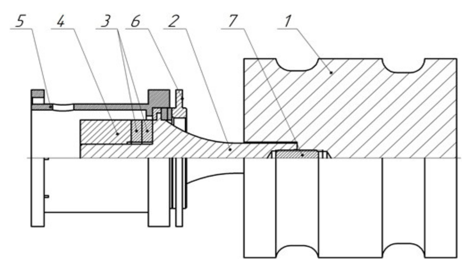
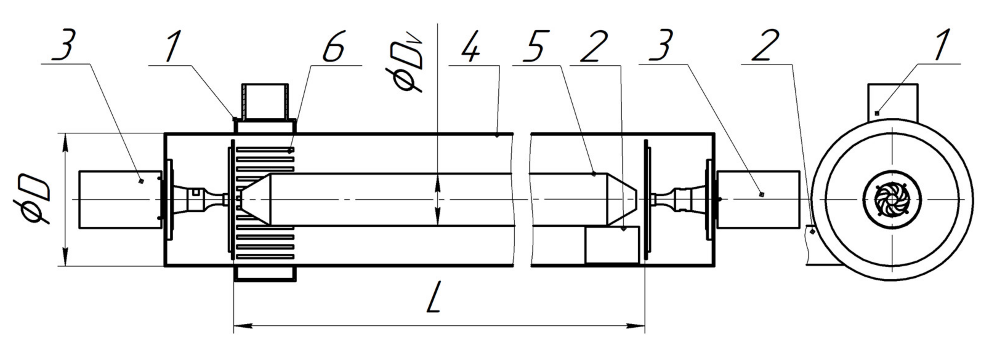
For the practical implementation of the process of coagulation of fine aerosols in the plane standing wave mode (the most frequent in practice), an ultrasonic oscillatory system with a longitudinally oscillating radiator was developed. The structure of this radiator was based on a resonant (half-wavelength) cylindrical body connected to an electroacoustic transducer. A sketch of the ultrasonic oscillation system together with a piston longitudinally oscillating radiator is shown in Figure 1 [26,27].
The creation of circular grooves has been suggested in order to maximize the steadiness of oscillations of the side surface [25,26,27].
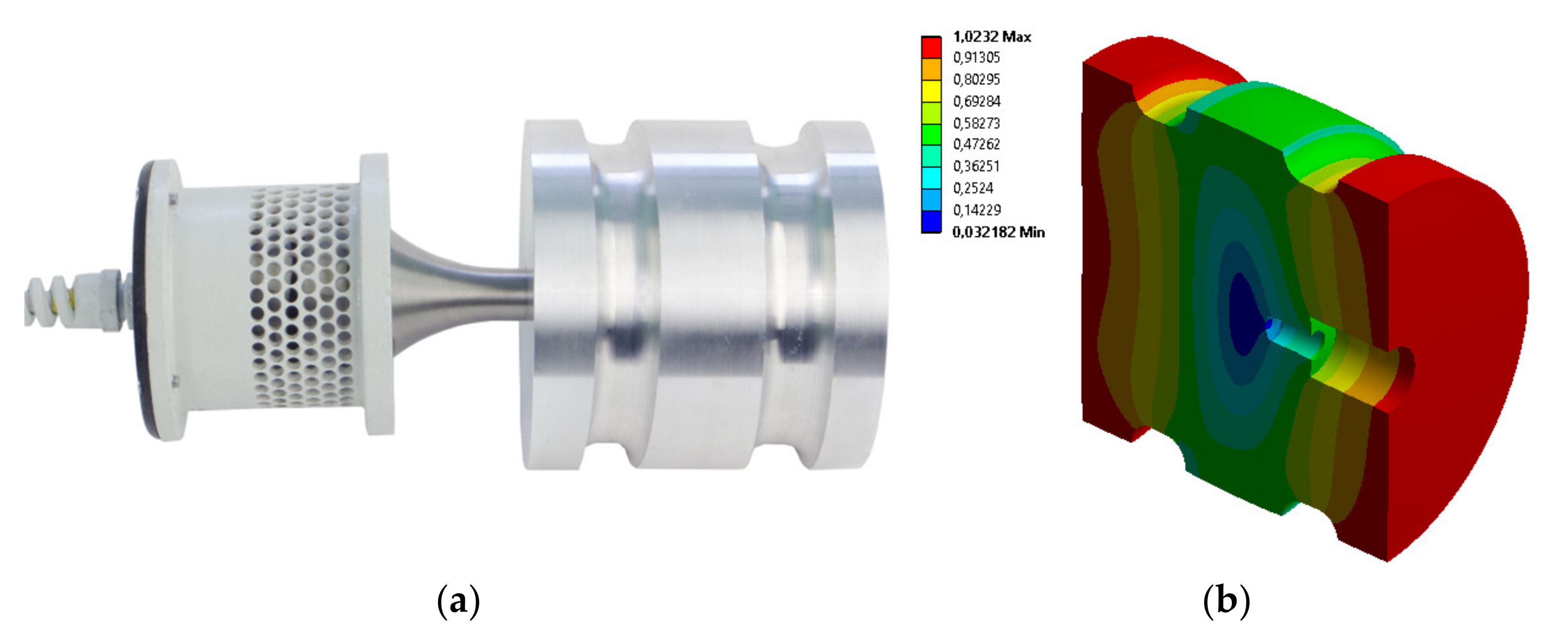
Figure 2 shows a picture of the ultrasonic oscillation system with a piston-type radiator and the radiator’s oscillation mode. The distribution of oscillations of the piston-type ultrasonic emitter was obtained by performing model analysis in the finite element modeling system in the COMSOL system [28].
Table 1 provides the main specifications of the piston-type ultrasonic radiator.
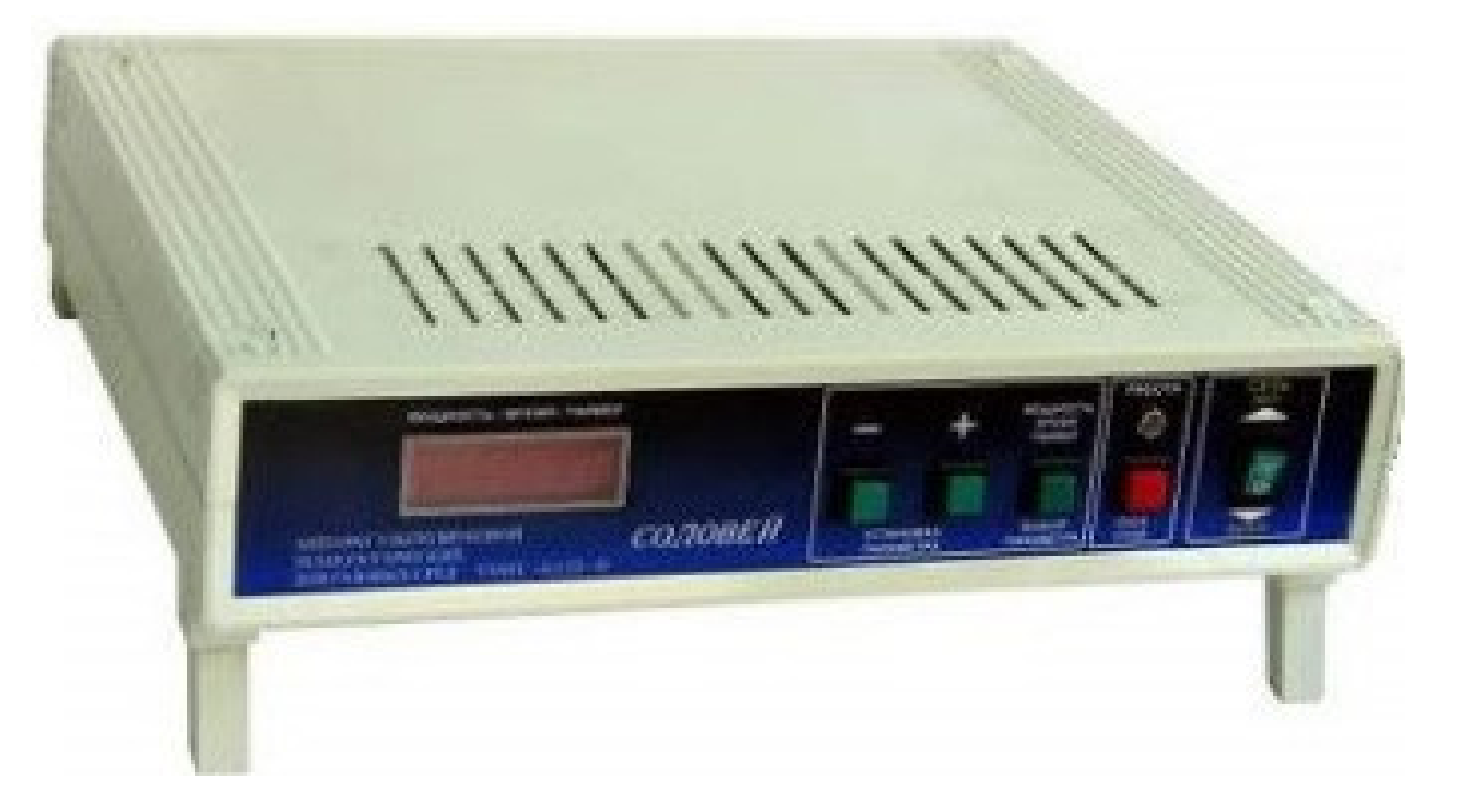
An ultrasonic generator Solovey USAGM-0,15/22-O (Figure 3), which was capable of generating a sound pressure level of 130…160 dB between the ultrasonic radiator and reflector, was used to supply power to the designed radiator. The generator is designed and manufactured by the authors of the article. The generator has a capability to make the settings and control the duration and power level of ultrasonic exposure [26,27,28,29]. Table 2 list the main technical characteristics.
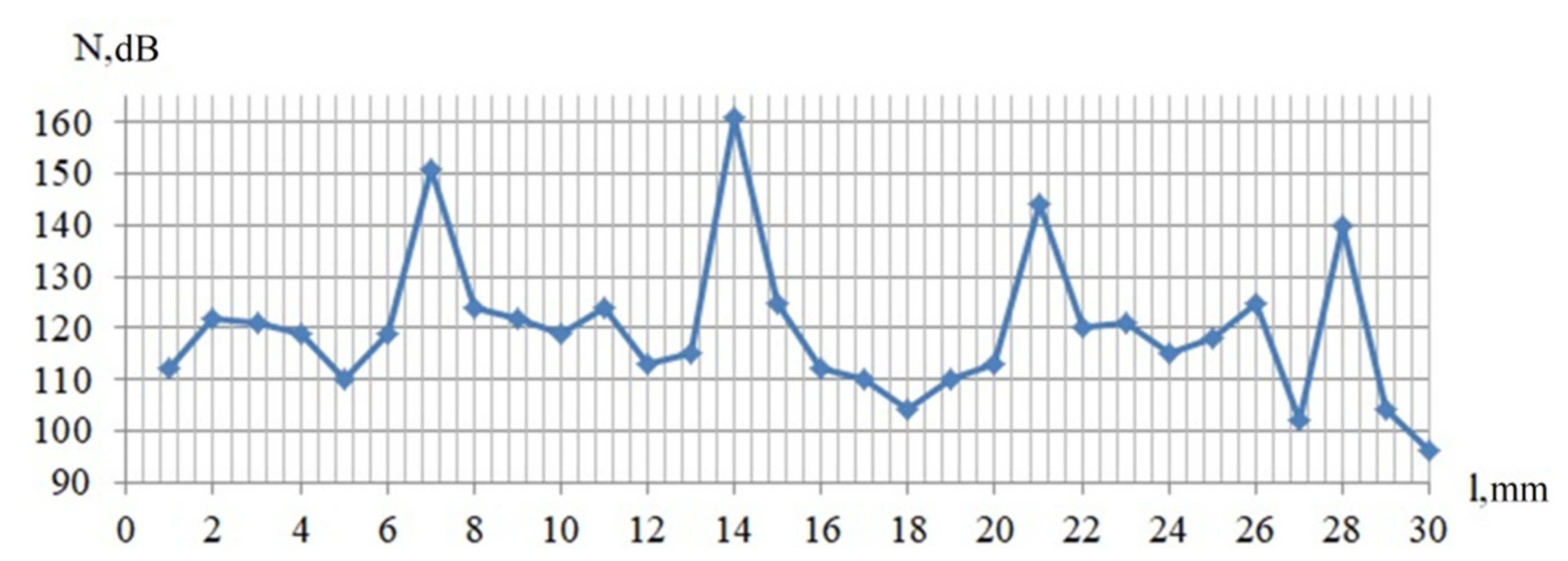
The sound pressure level was measured by means of an Ecophysica-110A noise level meter at different spacings between the surfaces of the used piston longitudinally oscillating radiator and reflector. The range of spacing during the measurements conducted is 1–30 mm.
The dependence of the sound pressure level on the spacing between the used piston longitudinally oscillating radiator and reflector is shown as the following curve (Figure 4).
It follows from the results of the measurements that the used radiator ensures the maximum sound pressure level of 160 dB at the resonant interval that equals 1 wavelength [30,31,32], which we consider a limit for implementation of the coagulation process featuring the highest possible efficiency.
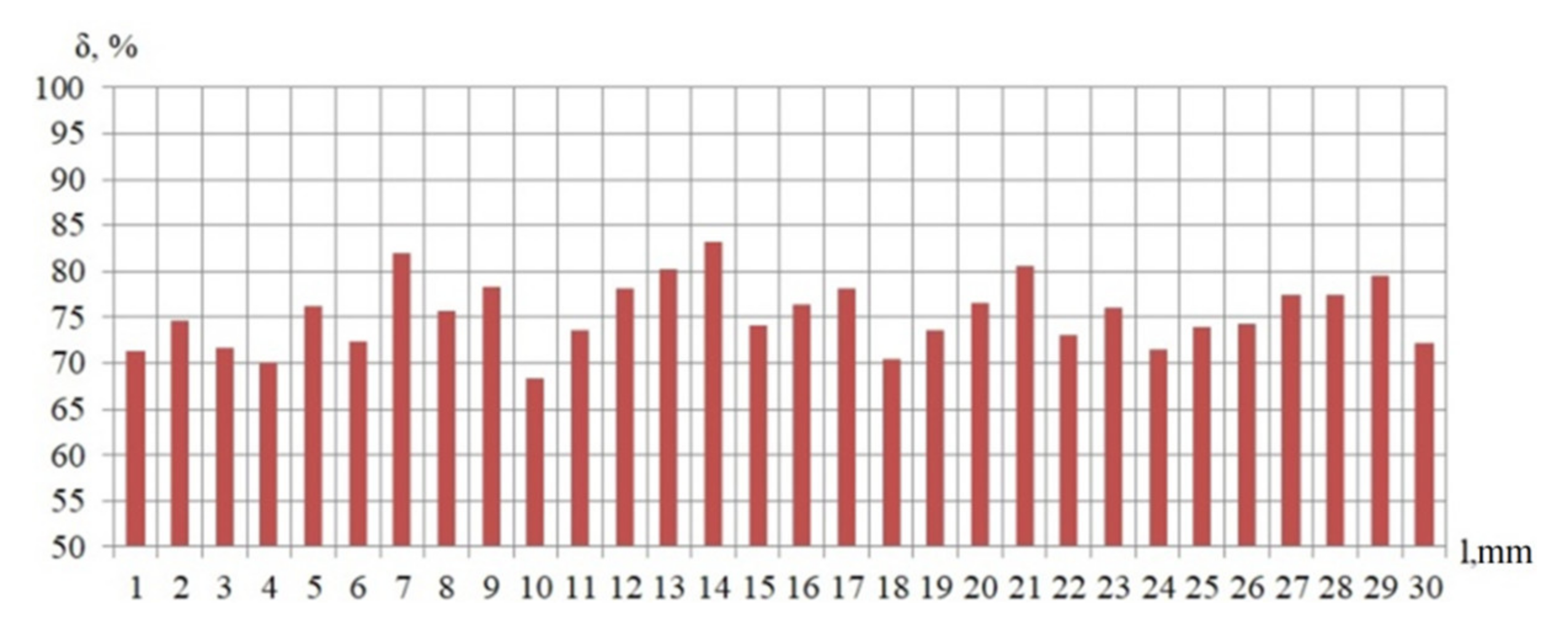
The results of analysis of the efficiency of ultrasonic coagulation for the piston longitudinally oscillating radiator depending on distance to the reflector are presented on the bar chart given in Figure 5.
It follows from the bar chart analysis that the coagulation efficiency peak falls within the segment of one wavelength of ultrasonic oscillations (14 mm). The coagulation efficiency reaches its maximum value at this distance.
Figure 6 shows the ratio of the coagulation efficiency to the sound pressure level obtained at the resonant distance between the piston-type radiator and reflector that equals the wavelength.
Analysis of the curve on Figure 6 made it possible to establish that the coagulation efficiency reaches its maximum value of 83% at a sound pressure level of 160 dB. This value should be considered the limiting efficiency of ultrasonic coagulation of particles with a size of 2.5 µm in the maximum possible power of ultrasonic exposure in the field of mechanical oscillations generated by a piston-type radiator.
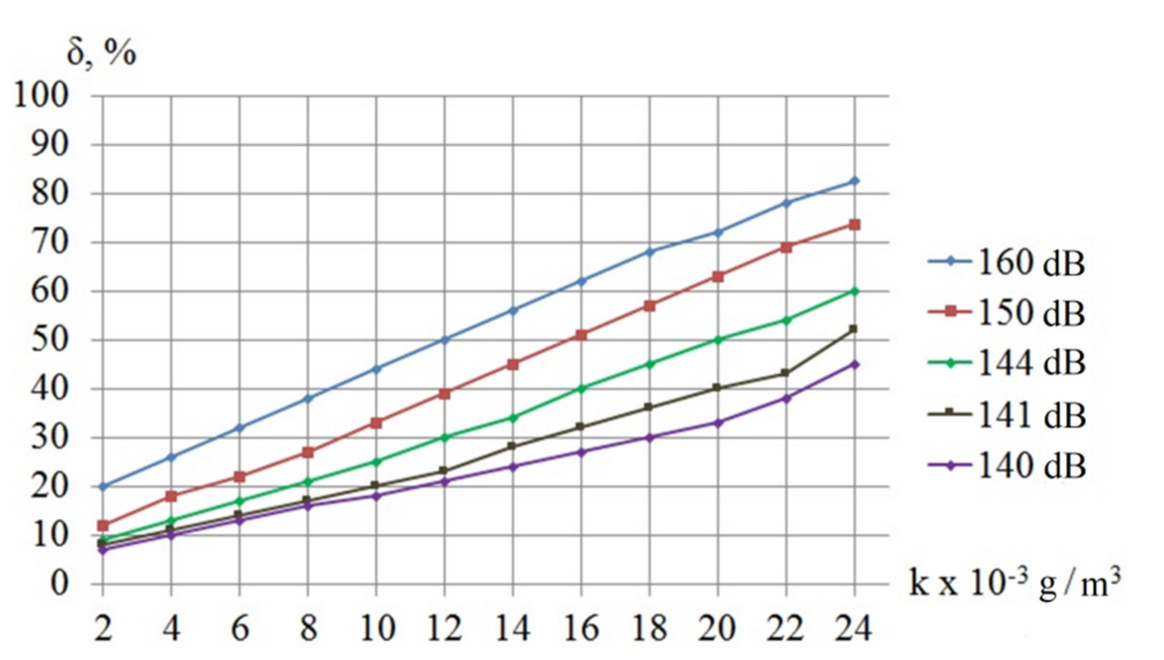
Further, experiments were carried out to study the efficiency of the coagulation process using a piston-type radiator at various concentrations of aerosol. Various aerosol concentrations were created by changing the aerosol volumetric flow at the outlet of the Topas ATM 226 compressor generator. The results of the experiment are shown in Figure 7.
As follows from the presented dependences, the coagulation efficiency essentially depends on the initial aerosol concentration. At low concentrations (2–4 g/m3), the coagulation efficiency in the plane standing wave mode (shaped by a flat radiator) does not exceed 30%, which renders its use impractical.
Thus, the studies carried out for the case of ultrasonic exposure in the plane standing wave mode made it possible to establish the limiting capabilities of ultrasonic coagulation of particles with a size of 2.5 µm and less, i.e., to identify that the value of the limiting efficiency of ultrasonic coagulation equals 83% at the investigated frequency of exposure.
Therefore, knowledge of the limiting capabilities of ultrasonic exposure leaves room to focus our efforts on searching for additional effects that can provide a further increase in efficiency.
Therefore, further analysis of the impact of gas flows carrying solid (or water) particles is self-evident.
3. The Method of Fine Particle Ultrasonic Coagulation in Swirling Flow
According to the available experimental data, the efficiency of cleaning of particles d = 2.5 µm by inertial gas treatment equipment is within 10–30%, i.e., requires a significant increase.
Since it is obvious that the energetic impact of ultrasonic oscillations is capable of generating a positive effect on the coagulation process of fine particles, a need arises to enable preliminary convergence of particles and the formation of regions with their increased concentration. This is most effectively ensured by creating optimum conditions for the swirling flow current with simultaneous ultrasonic exposure. The swirling flow is capable of generating the displacement of particles to the outer radius under the impact of centrifugal forces.
The displacement of particles will result in generation of an area with an increased concentration, in which the probability of collision and aggregation of particles under the impact of ultrasonic oscillations increases to values sufficient for subsequent capture in standard or upgraded devices utilizing the ultrasonic oscillations.
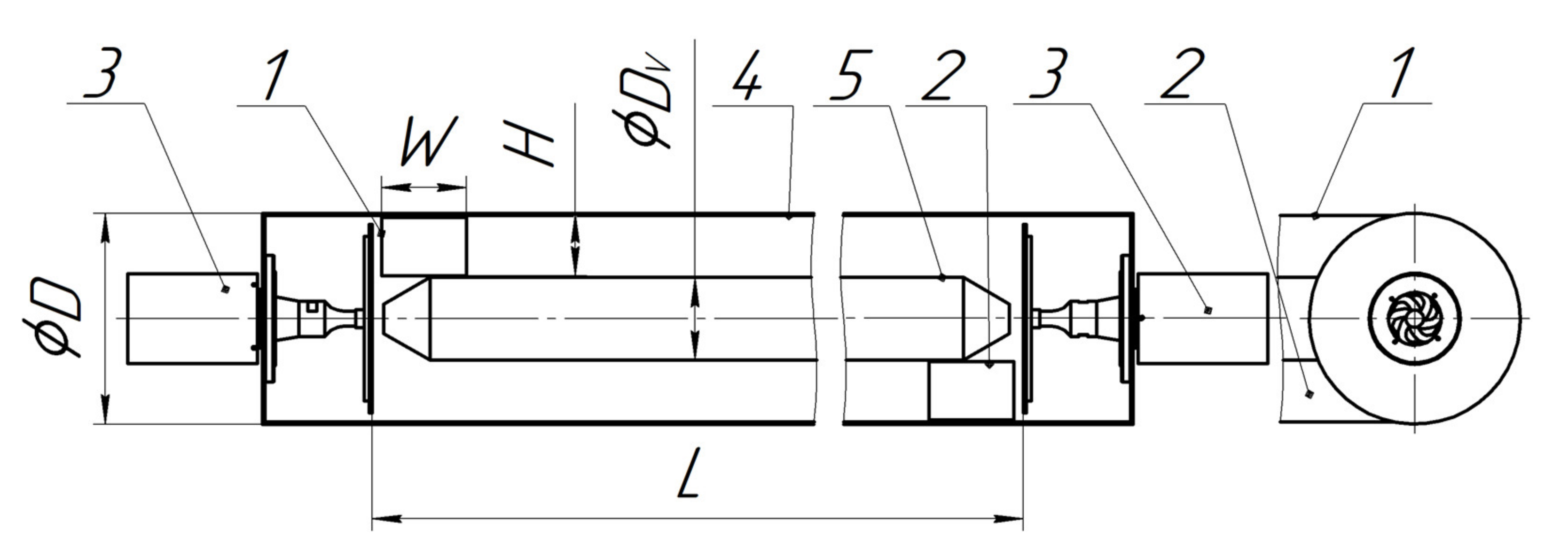
This method of coagulation can be implemented in a device (agglomerator) designed as a horizontally located cylindrical volume, equipped with tangential inlet and outlet ducts. The displacer eliminates the ingress of particles into the near-axial zone, in which the centrifugal forces are small. The displacer diameter equals 1/3 of the diameter of the agglomerator. A sketch of an agglomerator for generation of a swirling flow is shown in Figure 8.
To generate ultrasonic oscillations within the volume of the agglomerator, two ultrasonic disk radiators generating the ultrasonic oscillations with a frequency of at least 22 kHz need to be used. The choice of frequency is due to safety requirements for attending personnel and the high efficiency of the impact on small particles [29,30].
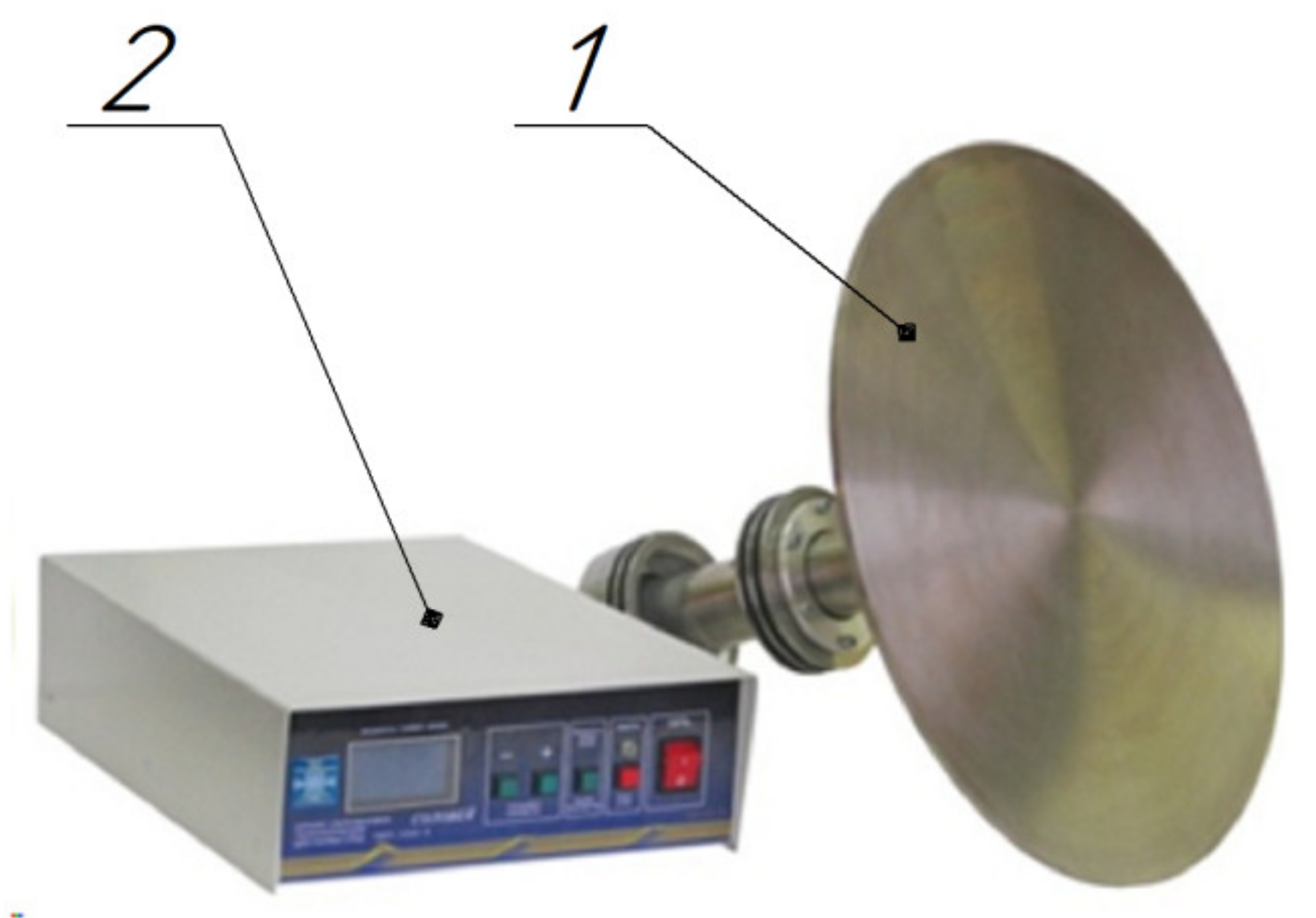
The appearance of the ultrasonic disk radiator with an electronic generator is shown in Figure 9, and its specifications are given in Table 3.
The agglomerator operates in the following manner. The gas flow containing dispersed particles enters the agglomerator through the tangential inlet duct. Inside the agglomerator, as a result of movement along a spiral trajectory, under the impact of centrifugal forces, the gas-dispersed flow is stratified and dispersed particles are displaced to the peripheral zone of the flow, in the direction of the outer casing of the agglomerator. There, the particles are subjected to ultrasonic exposure resulting in their convergence and the formation of agglomerates. An increase in the mass of agglomerates results in a further increase of the flow stratification degree. The gas flow containing agglomerates of dispersed particles exits the agglomerator through the outlet duct.
For maximum efficiency and uniformity of ultrasonic exposure, the inner diameter of the agglomerator corresponds to the diameter of the disk radiator. The length of the agglomerator is selected so that the time of exposure to ultrasonic oscillations of a particle moving in the flow is at least 1 s with a gas flow rate of Q = 0.28 m3/s (1000 m3/h).
The selected flow rates are typical for low-capacity gas treatment equipment and enable calculation of the length of the agglomerator using the following equation [32,33,34,35]:
where Q—gas flowrate, m3/s; T—time of exposure, s; D—diameter of agglomerator, m; Dv—diameter of displacer, m.
Taking into consideration that Dv = 1/3D, Equation (2) will be written in the following manner:
To ensure the minimum duration of ultrasonic exposure of 1 s, the length of the agglomerator shall be 3 m, at least. The height of the inlet and outlet tangential ducts correspond to:
The initial tangential velocity Vτ was limited by the value 15–20 m/s, since an increase of the gas velocity in the inlet duct of the cyclone above 20 m/s results in stronger turbulence and a decrease of the separation efficiency [22].
The width of the inlet and outlet ducts W with a selected capacity of Q = 0.28 m3/s (1000 m3/h) and tangential velocity (20 m/s) with reference to Equation (4) is estimated by means of the following equation:
To assess the efficiency of coagulation in the developed device, comparative tests were carried out with generation of such conditions in it that allowed directing of the gas-dispersed flow in a straight line.
To generate a straight-line flow (Figure 10), the tangential duct (Figure 8, item 1) with the cylindrical part of the body is replaced by a flow distributor (Figure 10, item 1). With this design, the gas-dispersed flow is supplied uniformly through slotted holes (Figure 10, item 6) designed in the cylindrical part of the body (item 4). This ensures a straight-line flow in the volume of the agglomerator.
Experimental studies were carried out at equal sound pressure levels generated by ultrasonic radiators in the inner volume of the agglomerator. The average sound pressure level was 145 dB (at a frequency of 22 kHz). In this case, the deviation from the average value at different measurement points does not exceed 3 dB. This indicated a sufficient sound pressure level for the coagulation of dispersed particles and its uniform distribution in the test bench [36,37,38].
Jetfine T1 CA microtalc was used as a dispersed material (true density: 2.69 g/cm3; bulk density 0.8 g/cm3 (according to the manufacturer’s data)). The dispersed particles were supplied with an ejection-type pneumatic sprayer installed in front of the agglomerator inlet duct. Conducted measurements have shown that a uniform distribution of particles with an average diameter of d = 2.5 µm over the flow is thus obtained.
Experimental studies in swirling and straight-line flows were carried out at a gas flow rate of 0.05 m3/s up to 0.4 m3/s. The concentration of particles injected at the inlet to the agglomerator was maintained at the value of N = 5 g/m3 throughout the studied gas flow rates.
The fractional composition in the particle size at the inlet and outlet of the experimental setup was determined by an LID-2M laser dispersion meter.
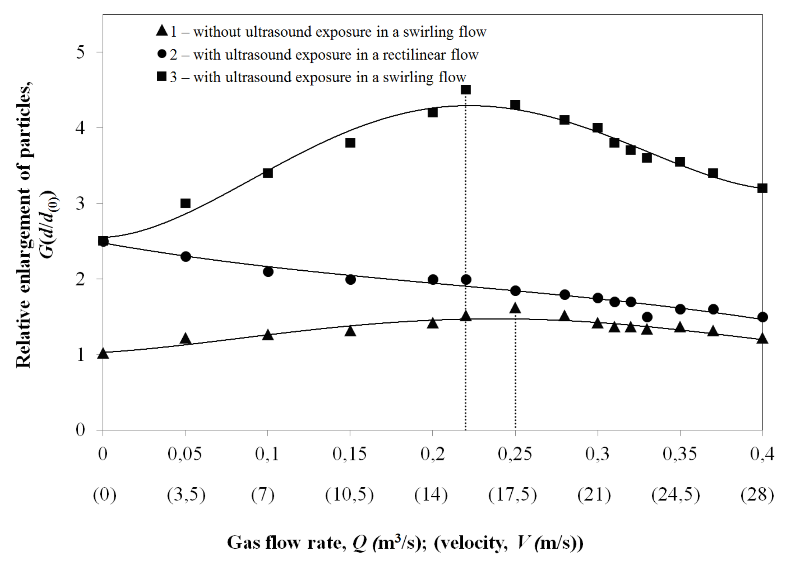
The obtained results are shown in Figure 11.
Analysis of the obtained results suggested the following conclusions:
- Generation of a swirling flow even without ultrasonic exposure (curve No. 1 in Figure 11) ensures the aggregation of particles at a flow rate of Q = 0.25–0.3 m3/s due to their spontaneous agglomeration by a factor of 1.6. This confirms the feasibility of using a swirling flow for a local increase in the concentration of particles in order to increase the probability of their collision.
- In the absence of gas flow, the superposition of ultrasonic oscillations provides a relative enlargement of particles up to 3 times (the starting point of graphs No. 2 and No. 3 in Figure 11). In this case, the maximum effect of ultrasonic exposure is observed in the first second of the experiment (particles increase in size up to 2 times). Over the next 10 s of the experiment, the particle size increases up to 3 times. Further ultrasonic exposure does not result in aggregation of particles due to a decrease in their concentration by up to 27 times (due to coagulation). As a result, the formed agglomerates cease to increase in size and settle under the effect of gravity.
- Generation of a swirling flow and its exposure to ultrasonic impact changes the dependence of the relative enlargement on the gas flow rate, ensuring an increase in the particle size up to 4.5 times.
- The maximum increase in the size of dispersed particles in a swirling flow under ultrasonic exposure is achieved at a gas flow rate of Q = 0.22 m3/s (800 m3/h). The extremum exists due to an increase in the tangential velocity of the swirling flow with an increase in the gas flow rate on the one hand and a decrease in the residence time of dispersed particles in the agglomerator with an increase in the gas flow rate, on the other hand.
Implementation of the proposed method of coagulation of fine particles (2.5 µm) and the conducted studies have made it possible to identify the flow conditions of the dispersed flow, which ensure the maximum relative enlargement of particles under ultrasonic exposure.
Evaluation of the effectiveness of ultrasonic exposure in the proposed method made it possible to establish that ultrasonic exposure applied to swirling flow ensures an increase in the cleaning efficiency of fine particles by up to 39% at a particle concentration of 5 g/m3.
This testifies to the effectiveness of the proposed method for increasing the efficiency of gas treatment by creating a swirling flow and subjecting it to ultrasonic exposure.
To confirm the efficiency of coagulation of particles of various sizes, experimental studies were carried out using microtalcs of various brands with average particle sizes of 1 to 17 µm at the identified optimum gas flow rate and at an initial particle concentration of N = 5 g/m3.
The implementation of the proposed coagulation method and the agglomerator that implements it as the first stage of the purification equipment (i.e., before the inertial gas handling equipment providing 30% coagulation) made it possible to ensure a maximum efficiency of capturing the fine dispersed particles of up to 85%.
Thus, an increase in the efficiency of ultrasonic agglomeration of dispersed particles less than 2.5 µm in size should be implemented due to the convergence of particles and generation of local zones with an increased concentration. This is most easily accomplished by generating such zones in the swirling flow.
Since the proposed method of coagulation implements ultrasonic exposure of a certain value by means of an actually existing radiator (145 dB), and the possibility of implementing the resonant amplification of ultrasound up to 160 dB has been shown previously, a need arises to search for ways to increase the efficiency of coagulation by combining the maximum ultrasound exposure with swirling flows.
4. The Method of Fine Particle Ultrasonic Coagulation with Maximum Ultrasonic Exposure in Swirling Flow
Obviously, the efficiency of coagulation of fine particles can be increased owing to an increased duration of ultrasonic exposure of each particle and creating zones of a local increase in the concentration of fine and fine particles. In practice, this can be achieved by way of generation of vortex flows between the radiating and reflecting surfaces. Such flows should ensure an increase in the efficiency of ultrasonic coagulation of particles smaller than 2.5 µm. Therefore, to further increase the efficiency of coagulation, a method of coagulation of fine particles with generation of fluxes in the resonant layer has been proposed.
To achieve such conditions of ultrasonic exposure, the radiator of ultrasonic oscillations was designed in a shape of a flexural-oscillating disk with central excitation from a piezoelectric oscillation system. As a rule, ultrasonic oscillations are excited at multiples of the fundamental oscillation mode (3, 5, 7, etc.)
Figure 12 shows a draft ultrasonic oscillation system with a radiator designed as a diametrically oscillating plate (disk) [25,26,39,40].
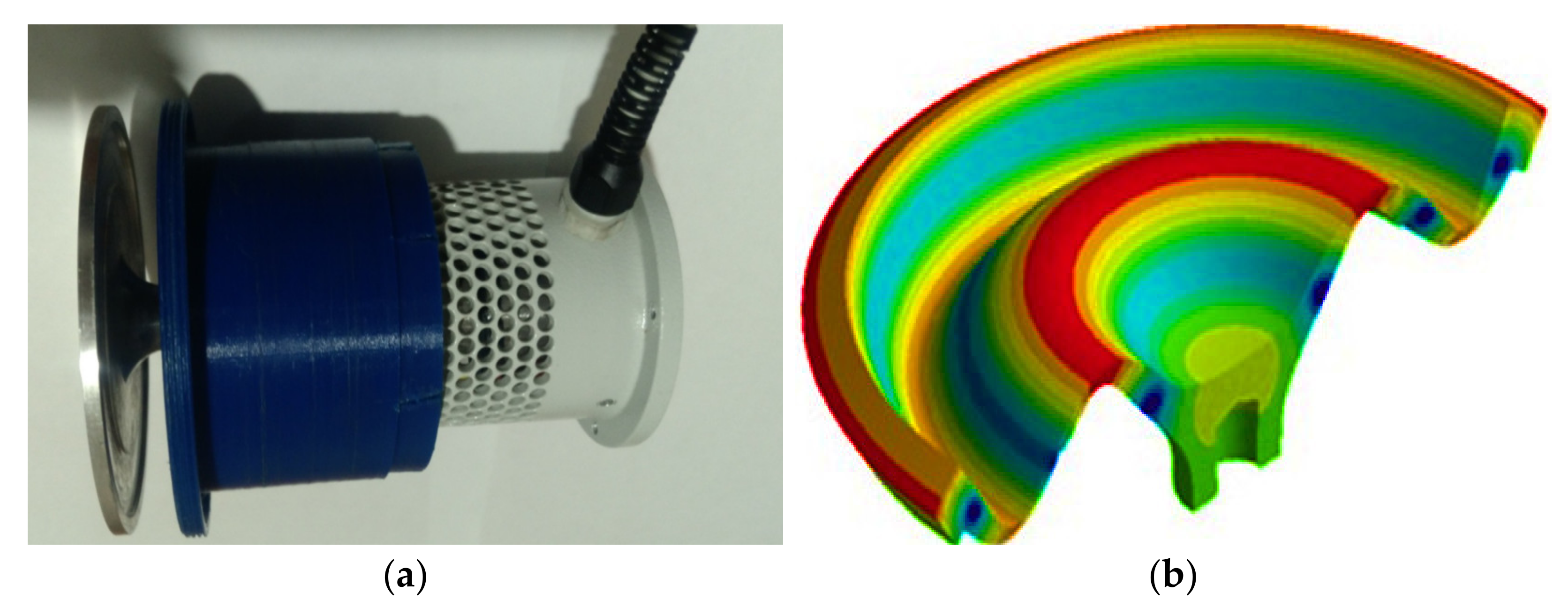
Figure 13 shows a picture of the ultrasonic oscillation system with a disk-type radiator and mode of oscillations of the disk-shaped radiating element. The distribution of oscillations of the piston-type ultrasonic emitter was obtained by performing model analysis in the finite element modeling system in the COMSOL system [28].
Table 4 lists the main specifications of the disk radiator in diametrical oscillations mode.
As follows from the presented shape of oscillations generated by such a radiator, it is capable of providing the required ultrasonic exposure for the implementation of the process of ultrasonic coagulation of fine particles in gaseous media [24,27]. At the same time, it enables generation of the vortex acoustic flows between the disk radiator and the reflector (Figure 14).
For the disk radiator, the vortex flow fills the entire gap between the radiator and reflector. Herewith, sedimentation of drops forming a circular pattern is observed at the reflector (Figure 15).
When the distance between the emitter and the reflector equals λ/4, the drops deposited on the surface of the reflector (formed as a result of ultrasonic coagulation of the aerosol) form concentric rings. Moreover, the inner rings have a more regular shape and a sharper border than the outer rings. At a distance of 7 and 14 mm, the structure of sedimentation is also regular; however, it is a combination of spots evenly covered with deposited drops and concentric rings. Herewith, the outer rings are not closed. This is apparently related to the structure of the acoustic field in the gap and the formed acoustic flows.
The vortex-type flows are not generated at distances less than 4 mm (λ/4) and more than 14 mm (λ). At the same time, significant turbulization of the gas-droplet suspension is observed at distances exceeding 14 mm, resulting in a decrease in the efficiency of aerosol coagulation. At the same time, chaotic sedimentation of large aerosol droplets with a diameter of 15–100 µm is observed on the reflector, that is, accelerated deposition of fine particles on the reflector is not observed.
Consequently, when analyzing the available data, it can be concluded that vortex acoustic flows appear in a thin gap between the disk-type radiator and the reflector at certain distances.
By analogy with a piston longitudinally oscillating radiator, the graph shows the results of measuring the sound pressure level for a flexural oscillating disk radiator relative to the distance to the reflecting surface (Figure 16).
Analysis of the graph in Figure 16 suggests that, similarly to a piston longitudinally oscillating radiator, a sound pressure level of 160 dB is generated at a resonant gap that equals to 1 wavelength [27,28,29,30,31,39]. In this case, the relative difference between the sound pressure levels generated by the disk and piston radiators, with the same distance from the reflector, does not exceed ± 2 dB over the entire range of distances. Consequently, the conditions for conducting experimental studies for both types of radiators were the same.
The equality of the sound pressure levels generated by the radiators of both types makes it possible to compare the efficiency of coagulation ensured by the radiator and to determine the effect of vortex flows created by the radiator in flexural oscillation mode on the efficiency of coagulation.
The results of the coagulation efficiency of the disk radiator are presented in Figure 17.
It follows from a comparison of the bar charts in Figure 5 and Figure 17 that for both radiators, the peak of the coagulation efficiency falls within a band of one wavelength of ultrasonic oscillations. The coagulation efficiency reaches its maximum at this distance.
Figure 18 shows the dependence of the coagulation efficiency on the sound pressure level, obtained at a resonant distance equal to the wavelength between the disk radiator and the reflector.
It follows from the obtained results that a coagulation efficiency that equals 96 % can be obtained for the disk radiator (against the 83 % for the piston-type radiator).
Thus, the efficiency of coagulation by means of a disk radiator, which creates vortex-type acoustic flows, is higher than when using a piston-type radiator by 13%. Because the experimental conditions were the same, then the specified increase can only be caused by the generation of vortex acoustic flows. During their generation, conditions are created for the drift of particles under the effect of centrifugal forces from the central zone of the vortex to its periphery. As a result, a local increase in the concentration of particles in the peripheral zone of the vortex is ensured, which increases the probability of collision, and, consequently, coagulation of particles as a result of exposure to ultrasonic oscillations.
Analysis of the curve presented on Figure 16 suggests that the coagulation efficiency of a disk radiator in diametrical oscillation modes reaches its maximum at lower sound pressure levels. For a disk radiator in diametrical oscillation mode, it can be seen that starting from a sound pressure level of 150 dB, the coagulation efficiency reaches its maximum value and, in fact, ceases to increase further (no more than 2%).
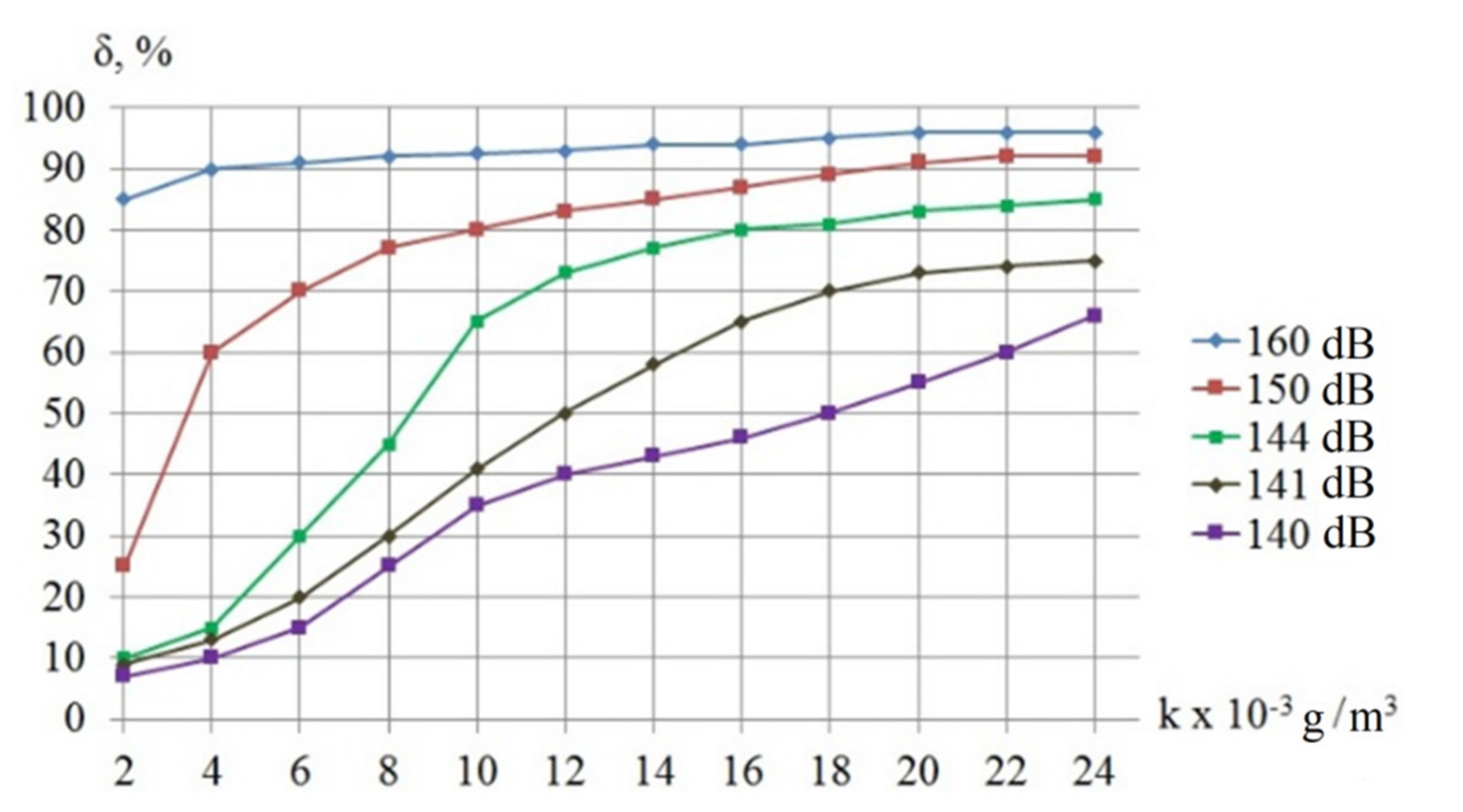
Additionally, similar experiments were conducted in order to study the efficiency of the coagulation process of a disk radiator with various concentrations of aerosol. The research results are presented in Figure 19.
It was established from comparison of the curves in Figure 7 and Figure 19 that the coagulation efficiency significantly exceeds the efficiency of a piston-type radiator when a disk radiator is used at a low concentration of particles. The efficiency of coagulation with application of a piston-type radiator with an increase in the particle concentration increases linearly and reaches its maximum value of 83% at a concentration value of 24 × 10−3 g/m3, while the efficiency reached its maximum of 96% at a concentration as low as 18 × 10−3 g/m3 when a disk radiator was used. As already mentioned, both radiators operated at the same sound pressure level; therefore, it can be assumed that such a difference is associated with the generation of vortex acoustic flows by the flexural-oscillating disk radiator.
At high initial aerosol concentrations, ultrasonic exposure with generation of vortex flows by a disk radiator is advisable to use at the final stage of the coagulation process, when the concentration of particles decreases owing to the action of ultrasonic oscillations, which results in a quadratic decrease in the probability of particle agglomeration, and, as a consequence, that of ultrasonic coagulation efficiency. The generation of vortex flows is effective for media with a low concentration of particles. This is due to the fact that with the characteristic distances between suspended particles being much larger than their size, the forces of hydrodynamic interaction of particles and the amplitude of their oscillating motion appear to be insufficient to bring the particles closer together to the distance sufficient for their aggregation. Additionally, the concentration increases locally due to vortex flows, and owing to this, coagulation has a greater efficiency than without vortex flows [34,35,36,40].
5. A Device for Practical Implementation of the Proposed Ultrasonic Coagulation Method by Means of Vortex Flows
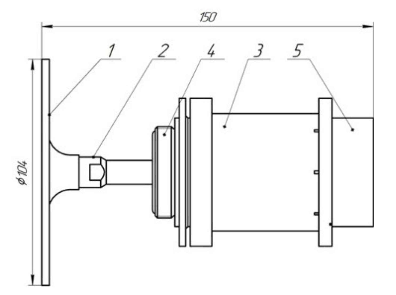
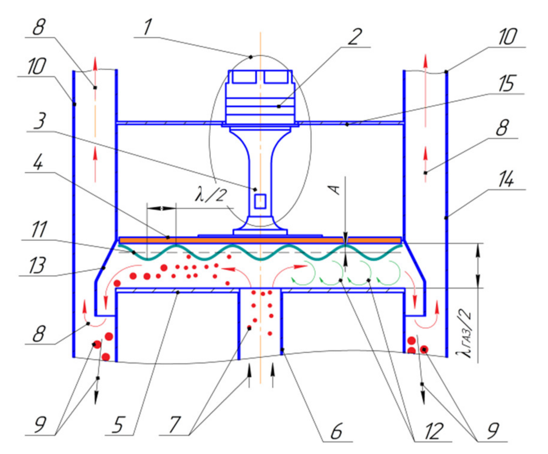
For the practical implementation of ultrasonic coagulation using vortex flows, a practical design is proposed, shown in Figure 20, in which a piezoelectric oscillatory system (1) consisting of a piezoelectric transducer of electrical oscillations into mechanical oscillations (2), a hub-amplifier of mechanical oscillations (3), and a radiator as an operating tool in the form of a plate (disk) (4) with a flat radiating surface, which is used to create high-intensity acoustic fields. A surface (5) reflecting ultrasonic oscillations is installed in front of the radiating surface. Thus, the ultrasonic oscillation system is installed on top of the coagulation chamber formed between the radiating and reflecting surfaces.
Through the inlet (6), which is located in the central part of the reflecting surface, gas (7) contaminated with particles is supplied, and it is distributed to the peripheral zones of the reflecting surface area in the coagulation chamber. The treated gas (8) and coagulated particles (9) (aggregated and increased in size) are removed outside the process volume through the outlet ducts (10). In the process of gas flow between two planes (reflector and radiator), ultrasonic exposure is applied by a flexural-oscillating plate, on the flat radiating surface of which maximums and minimums of oscillations are generated, alternating sequentially at a distance from each other corresponding to half the wavelength of flexural oscillations in the plate material at a frequency of at least 22 kHz with an intensity of at least 160 dB.
A plate with a flat radiating surface forms a sinusoidal distribution of the amplitudes of mechanical oscillations (11) in the gap between the radiating and reflecting surfaces. Due to generation of differently directed oscillating motions in segments differing in phases by 180 degrees (conditions for creating a vacuum and increased pressure on the gas zone), vortex flows (12) are generated. As they fall into these vortex flows, the foreign particles are subjected to ultrasonic exposure for a longer time, and conditions for an increase in the concentration of particles in areas where the direction of their movement is changed are generated.
Herewith, as the particles are moving to the peripheral zone of the coagulation chamber, they alternatively end up in every subsequent generated vortex, increasing their size. After coagulation, the particles are carried away by the air flow to the peripheral zones of the chamber, where the particles collide with a partition (13), the purpose of which is to separate the purified air and coagulated particles. The purpose of the case (14) is to provide protection of the components located inside from mechanical damage during operation or storage, as well as to protect against dust, moisture, and any other external impacts. An ultrasonic oscillation system is secured to the flange (15).
Thus, in the proposed device for ultrasonic coagulation, the generation of vortex flows due to generation of ultrasonic oscillations in the resonant gap significantly increases the duration and efficiency of ultrasonic exposure applied to the particles polluting the gas, and, consequently, the very efficiency of the particle coagulation process.
6. Conclusions
As a result of the studies, the limits of ultrasonic exposure’s impact on the process of coagulation of fine particles with a size of 2.5 microns and less at a frequency of 22–23 kHz were revealed.
It was established that ultrasonic exposure with a maximum sound pressure level of 160 dB can be implemented in resonant gaps between the radiating and reflecting surfaces located at a distance that equals the length of applied ultrasonic oscillations and is capable of ensuring coagulation of particles with a size of 2.5 µm with an efficiency 83% (Figure 6).
It was found that generation of swirling flows in the field of ultrasonic exposure causes an additional increase in the efficiency of ultrasonic coagulation up to 13% (Figure 18).
To further increase the efficiency, implementation of ultrasonic coagulation in the resonant layer with generation of vortex flows was proposed, and a new method for the treatment of gases from dispersed particles less than 2.5 µm in size was developed by increasing the duration of ultrasonic exposure applied to each particle and creating zones of a local increase of the concentration of fine particles. A coagulation efficiency of δ = 96% was ensured owing to the generation of vortex flows between the radiating and reflecting surfaces (Figure 19).
An optional lowering (up to 150 dB) of the sound pressure level, required to ensure the maximum efficiency of coagulation, should be ranked among the advantages of the proposed method of coagulation.
The practical implementation of the proposed method showed that the generation of vortex acoustic flows is most expedient for the coagulation of aerosols of low concentrations. Thus, for a concentration of 18∙10−3 g/m3, the increase in efficiency as a result of the generated vortex flows is up to 50% (Figure 19). At high initial aerosol concentrations, it is advisable to use ultrasonic exposure with the generation of vortex flows at the final stage of the coagulation process, when the concentration of particles decreases due to the impact of ultrasonic oscillations, which results in a quadratic decrease in the probability of particle agglomeration, and, as a consequence, that of the efficiency of ultrasonic coagulation.
A device that is applicable to practical implementation of the proposed method of ultrasonic coagulation was designed, which is acceptable for practical implementation when designing units for the treatment of gases from fine contaminating particles.
Author Contributions
Data curation, V.N.K. and A.V.S.; Formal analysis, A.V.S.; Investigation, V.N.K., V.A.N., A.S.B. and A.V.S.; Methodology, V.N.K. and V.A.N.; Project administration, V.N.K.; Validation, V.N.K. and A.V.S.; Visualization, V.A.N.; Writing—original draft, V.N.K.; Writing—review and editing, A.S.B. All authors have read and agreed to the published version of the manuscript.
Funding
This research was funded by a grant from the Russian Science Foundation (Project No. 19-19-00121).
Conflicts of Interest
The authors declare no conflict of interest.
References
- Yang, L.; Bao, J.; Yan, J.; Liu, J.; Song, S.; Fan, F. Removal of fine particles in wet flue gas desulfurization system by heterogeneous condensation. Chem. Eng. J. 2010, 156, 25–32. [Google Scholar] [CrossRef]
- Chang, Q.; Zheng, C.; Gao, X.; Chiang, P.; Fang, M.; Luo, Z.; Cen, K. Systematic approach to optimization of submicron particle agglomeration using ionic-windassisted pre-charger. Aerosol Air Qual. Res. 2015, 15, 2709–2719. [Google Scholar] [CrossRef] [Green Version]
- Fan, F.; Yang, L.; Yan, J.; Bao, J.; Shen, X. Experimental investigation on removal of coal-fired fine particles by condensation scrubber. Chem. Eng. Process. 2009, 48, 1353–1360. [Google Scholar] [CrossRef]
- Hoffmann, T.L. Environmental implications of acoustic aerosol agglomeration. Ultrasonics 2000, 38, 353–357. [Google Scholar] [CrossRef]
- Liu, J.; Zhang, G.; Zhou, J.; Wang, J.; Zhao, W.; Cen, K. Experimental study of acoustic agglomeration of coal-fired fly ash particles at low frequencies. Powder Technol. 2009, 193, 20–25. [Google Scholar] [CrossRef]
- Fan, F.; Yang, X.; Kim, C.N. Direct simulation of inhalable particle motion and collision in a standing wave field. J. Mech. Sci. Technol. 2013, 27, 1707–1712. [Google Scholar] [CrossRef]
- Patterson, H.S.; Cawood, W. Phenomena in a sounding tube. Nature 1931, 127, 667. [Google Scholar] [CrossRef]
- Capperan, P.; Somers, J.; Richter, K.; Fourcaudot, S. Accoustic agglomeration of a glycol for aerosol: Influence of particle concentration and intensity of the sound field at two frequencies. Aerosol Sci. 1995, 26, 595–612. [Google Scholar] [CrossRef]
- De Sarabia, E.R.; Elvira-Segura, L.; Gonzalez-Gomez, I.; Rodrguez-Maroto, J.; Muoz-Bueno, R.; Dorronsoro-Areal, J.L. Investigation of the influence of humidity on the ultrasonic agglomeration of submicron particles in diesel exhausts. Ultrasonics 2004, 41, 277–281. [Google Scholar] [CrossRef]
- Kilikevičienė, K.; Kačianauskas, R.; Kilikevičius, A.; Maknickas, A.; Vainorius, D. Experimental investigation of acoustic agglomeration of diesel engine exhaust particles using new created acoustic chamber. Power Technol. 2019, 360, 421–429. [Google Scholar] [CrossRef]
- Zhang, G.X.; Ma, Z.F.; Wu, L.T.; Yao, H.H.; Chim, Z.H. Experimental study on acoustic agglomeration of fine droplet aerosol. Proc. CSEE 2020, 39, 608–614. [Google Scholar]
- Riera, E.; Cardoni, A.; Gallego-Juárez, J.A.; Acosta, V.M.; Blanco, A.; Rodríguez, G.; Blasco, M.; Herranz, L.E. Recent advances in the development and application of power ultrasonic plate transducers in gas dense extraction and particle agglomeration processes. Phys. Procedia 2015, 63, 67–72. [Google Scholar] [CrossRef] [Green Version]
- Gonzalez, I.; Gallego-Juárez, J.A.; Riera, E. The influence of entrainment on acoustically induced interactions between aerosol particles—An experimental study. J. Aerosol Sci. 2003, 34, 1611–1631. [Google Scholar] [CrossRef]
- Hoffmann, T.L.; Koopmann, G.H. Visualization of acoustic particle interaction and agglomeration: Theory and experiments. J. Acoust. Soc. Am. 1996, 99, 2130–2141. [Google Scholar] [CrossRef]
- Hoffmann, T.L.; Koopmann, G.H. Visualization of acoustic particle interaction and agglomeration: Theory evaluation. J. Acoust. Soc. Am. 1997, 101, 3421–3429. [Google Scholar] [CrossRef]
- González, I.; Hoffmann, T.L.; Gallego, J.A. Precise measurements of particle entrainment in a standingwave acoustic field between 20 and 3500 Hz. J. Aerosol Sci. 2000, 31, 1461–1468. [Google Scholar] [CrossRef]
- Cleckler, J.; Elghobashi, S.; Liu, F. On the motion of inertial particles by sound waves. Phys. Fluids. 2012, 24, 033301. [Google Scholar] [CrossRef]
- Zhang, G.; Liu, J.; Wang, J.; Zhou, J.; Cen, K. Numerical simulation of acoustic wake effect in acoustic agglomeration under Oseen flow condition. Chin. Sci. Bull. 2012, 57, 2404–2412. [Google Scholar] [CrossRef] [Green Version]
- Tkachenko, L.A. Dynamic of aerosols in the acoustic wave field in the tube. In Actual Problems of Continuum Mechanics; Federal Researcg Center «Kazan Scientific Center of Russian Academy of Sciences»: Kazan, Russia, 2016; pp. 100–114. [Google Scholar]
- Holonen, J.; Lanki, T.; Yli-Tuomi, T.; Tiittanen, P.; Kulmala, V.; Pekkanen, J. Particulate air pollution acute cardio respiratory hospital admissions and mortality among the elderly. Am. J. Epidemiol. 2009, 20, 143–153. [Google Scholar]
- Andres, R.R.; Acosta, V.M.; Lucas, M.; Riera, E. Modal analysis and nonlinear characterization of an airborne power ultrasonic transducer with rectangular plate radiator. Ultrasonic 2018, 82, 345–356. [Google Scholar] [CrossRef] [Green Version]
- Kudryashova, O.B.; Pavlenko, A.A.; Vorozhtsov, B.I.; Titov, S.S.; Arkhipov, V.A.; Bondarchuk, S.S.; Maksimenko, E.V.; Akhmadeev, I.R.; Muravlev, E.V. Remote optical diagnostics of nonstationary aerosol media in a wide range of particle sizes. Photodetectors 2012, 15, 341–364. [Google Scholar]
- Kudryashova, O.B.; Akhmadeev, I.R.; Pavlenko, A.A.; Arkhipov, V.A.; Bondarchuk, S.S. A method for laser measurement of disperse composition and concentration of aerosol particles. Key Eng. Mater. 2010, 437, 179–183. [Google Scholar] [CrossRef]
- Khmelev, V.N.; Shalunov, A.V.; Bochenkov, A.V.; Nesterov, V.A. Experimental study of the process of ultrasonic coagulation of aerosols. In Measurements, automation and modeling in industry and scientific research, Materials of the XIV All-Russian Scientific and Technical Conference of Students, Postgraduates and Young Scientists with International Participation; Altai State Technical University: Biysk, Russia, 2019; pp. 243–248. [Google Scholar]
- Khmelev, V.N.; Shalunov, A.V.; Bochenkov, A.S.; Nesterov, V.A.; Terentiev, S.A.; Zorin, S.S. Experimental Stand for the Research of the Process of Ultrasonic Coagulation of Aerosols. In Proceedings of the 20th International Conference of Young Specialists on Micro/Nanotechnologies and Electron Devices, EDM’2019: Conference, Erlagol, Russia, 29 June–3 July 2019; NSTU: Novosibirsk, Russia, 2019; pp. 221–226. [Google Scholar]
- Khmelev, V.N.; Nesterov, V.A.; Shalunov, A.V.; Barsukov, R.V.; Tsyganok, S.N. Longitudinally oscillating ultrasonic emitter for influencing gas-dispersed systems. J. Phys. Conf. Ser. 2020, 1679, 022008. [Google Scholar] [CrossRef]
- Khmelev, V.N.; Shalunov, A.V.; Nesterov, V.A. Summation of high-frequency Langevin transducers vibrations for increasing of ultrasonic radiator power. Ultrasonic 2021, 114, 106413. [Google Scholar] [CrossRef]
- Gallego-Juarez, J.A.; Rodriguez, G.; Acosta, V.; Riera, E. Power ultrasonic transducer with extensive radiator for industrial processing. Ultrason. Sonochem. 2010, 17, 954–964. [Google Scholar] [CrossRef]
- Gallego-Juarez, J.A.; Rpdroguez-Corral, G.; Gaete-Garreton, L. An ultrasonic transducer for high power applications in gases. Ultrasonic 1998, 16, 267–271. [Google Scholar] [CrossRef]
- Gallego-Juarez, J.A.; Rodriguez, J.A.; Riera, E.; Acosta, V.M.; Montoya, F.; Blanco, A. Advances in the development of power ultrasonic technologies based on the stepped plate transducers. In Proceedings of the 36th Annual Symposium: Ultrasonic Industry Association, Teddington, UK, 19–21 March 2007. [Google Scholar]
- Surmen, A.; Avci, A.; Karamangil, M.I. Prediction of the maximum-efficiency cyclone length for a cyclone with a tangential entry. Powder Technol. 2011, 207, 1–8. [Google Scholar] [CrossRef]
- Xie, B.; Li, S.; Jin, H.; Hu, S.; Wang, F.; Zhou, F. Analysis of the performance of a novel dust collector combining cyclone separator and cartridge filter. Powder Technol. 2018, 339, 695–701. [Google Scholar] [CrossRef]
- Misiulia, D.; Andersson, G.A.; Staffan Lundström, T. Effects of the inlet angle on the collection efficiency of a cyclone with helical-roof inlet. Powder Technol. 2018, 305, 48–55. [Google Scholar] [CrossRef]
- Mazyan, W.I.; Ahmadi, A.; Ahmed, M.; Hoorfar, M. Increasing efficiency of natural gas cyclones through addition of tangential chambers. J. Aerosol Sci. 2017, 110, 36–42. [Google Scholar] [CrossRef]
- Ta-Chih, H.; Sheng-Hsiu, H.; Chia-Wei, H.; Chih-Chieh, C.; Po-Kai, C. Effects of the geometric configuration on cyclone performance. J. Aerosol Sci. 2015, 86, 1–12. [Google Scholar]
- Khmelev, V.N.; Shalunov, A.V.; Nesterov, V.A.; Dorovskikh, R.S.; Golykh, R.N. Ultrasonic radiators for the action on gaseous media at high temperatures. In Proceedings of the EDM’2015: Conference, Erlagol, Russia, 29 June–3 July 2015; NSTU: Novosibirsk, Russia, 2015; pp. 224–228. [Google Scholar]
- Khmelev, V.N.; Shalunov, A.V.; Dorovskikh, R.S.; Golykh, R.N.; Nesterov, V.A. The measurements of acoustic power introduced into gas medium by the ultrasonic apparatuses with the disk-Type radiators. In Proceedings of the EDM’2016: Conference, Erlagol, Russia, 30 June–4 July 2016; NSTU: Novosibirsk, Russia, 2016; pp. 251–256. [Google Scholar]
- Timoshenko, V.I.; Chernov, N.N. Sedimentation and Sedimentation of Industrial Fumes; Rostizdat: Rostov-on-Don, Russia, 2004; p. 224. [Google Scholar]
- Liu, J.; Wang, J.; Zhang, G.; Zhou, J.; Cen, K. Frequency comparative study of coal-fired fly ash acoustic agglomeration. J. Environ. Sci. 2011, 23, 1845–1851. [Google Scholar] [CrossRef]
- Song, L.; Koopman, G.; Hoffmann, T. An improved theoretical model of acoustic ag-glomeration. J. Vib. Acoust. 1994, 116, 208–214. [Google Scholar] [CrossRef]
Figure 1.
Sketch of the ultrasonic oscillation system with a piston radiator: (1) ultrasonic oscillations radiator; (2) concentrator of piezoelectric transducer; (3) piezoceramic elements; (4) reflector patch; (5) body; (6) flange; (7) pin.
Figure 1.
Sketch of the ultrasonic oscillation system with a piston radiator: (1) ultrasonic oscillations radiator; (2) concentrator of piezoelectric transducer; (3) piezoceramic elements; (4) reflector patch; (5) body; (6) flange; (7) pin.

Figure 2.
Picture of a piston-type ultrasonic radiator (a) and distribution of oscillations of the piston-type ultrasonic radiator (b).
Figure 2.
Picture of a piston-type ultrasonic radiator (a) and distribution of oscillations of the piston-type ultrasonic radiator (b).

Figure 3.
Ultrasonic generator.

Figure 4.
The sound pressure level curve depending on the spacing between the surface of the piston longitudinally oscillating radiator and reflector surface.
Figure 4.
The sound pressure level curve depending on the spacing between the surface of the piston longitudinally oscillating radiator and reflector surface.

Figure 5.
Bar chart of the efficiency of coagulation depending on the distance between the surface of the piston longitudinally oscillating radiator and reflector surface.
Figure 5.
Bar chart of the efficiency of coagulation depending on the distance between the surface of the piston longitudinally oscillating radiator and reflector surface.

Figure 6.
Ratio of the ultrasonic coagulation efficiency to the sound pressure level for the piston radiator.
Figure 6.
Ratio of the ultrasonic coagulation efficiency to the sound pressure level for the piston radiator.

Figure 7.
Dependence of the coagulation efficiency on the initial concentration of aerosol for the piston-type radiator.
Figure 7.
Dependence of the coagulation efficiency on the initial concentration of aerosol for the piston-type radiator.

Figure 8.
Sketch of an agglomerator with a tangential inlet duct for generation of the swirling flow. 1—tangential inlet duct; 2—outlet duct; 3—ultrasonic disk radiator; 4—outer casing of the agglomerator; 5—displacer; D—diameter of agglomerator; L—length of agglomerator; H—height of inlet and outlet ducts; W—length of inlet and outlet ducts.

Figure 9.
Appearance of the ultrasonic disk radiator. 1—ultrasonic oscillation system with a disk radiator; 2—electronic generator.
Figure 9.
Appearance of the ultrasonic disk radiator. 1—ultrasonic oscillation system with a disk radiator; 2—electronic generator.

Figure 10.
Sketch of the agglomerator with a flow distributor (straight-line flow) 1– inlet duct with flow distributor; 2—outlet duct; 3—ultrasonic disk radiator; 4—outer casing of the agglomerator; 5—displacer; 6—slotted holes of the flow distributor; D—diameter of agglomerator; L—length of agglomerator; H—height of inlet and outlet ducts; W—length of inlet and outlet ducts.

Figure 11.
Relative enlargement (G) of particles depending on the flowrate and velocity of gas flow (Q) at different modes of gas flow.
Figure 11.
Relative enlargement (G) of particles depending on the flowrate and velocity of gas flow (Q) at different modes of gas flow.

Figure 12.
Sketch of the ultrasonic oscillation system with a radiator designed as a flat disk in diametrical oscillation mode: (1) radiator shaped as a disk; (2) piezoelectric transducer; (3) the body of the ultrasonic oscillation system; (4) flange; (5) blower.
Figure 12.
Sketch of the ultrasonic oscillation system with a radiator designed as a flat disk in diametrical oscillation mode: (1) radiator shaped as a disk; (2) piezoelectric transducer; (3) the body of the ultrasonic oscillation system; (4) flange; (5) blower.

Figure 13.
Picture of the disk radiator in diametrical oscillation mode (a); oscillation mode of the disk radiator (b).
Figure 13.
Picture of the disk radiator in diametrical oscillation mode (a); oscillation mode of the disk radiator (b).

Figure 14.
Generated acoustic vortex-type flows of the disk radiator.

Figure 15.
Structures’ format at the reflector by the deposited drops depending on the distance (l) between the disk radiator and the reflector.
Figure 15.
Structures’ format at the reflector by the deposited drops depending on the distance (l) between the disk radiator and the reflector.

Figure 16.
The curve of the sound pressure level depending on spacing between the disk radiator surface and reflector surface.
Figure 16.
The curve of the sound pressure level depending on spacing between the disk radiator surface and reflector surface.

Figure 17.
Bar chart of the efficiency of coagulation depending on the distance between the disk radiator surface and reflector surface.
Figure 17.
Bar chart of the efficiency of coagulation depending on the distance between the disk radiator surface and reflector surface.

Figure 18.
The ratio of the coagulation efficiency on the sound pressure level for the disk radiator.
Figure 18.
The ratio of the coagulation efficiency on the sound pressure level for the disk radiator.

Figure 19.
Dependence of the coagulation efficiency on the initial concentration for the disk radiator.
Figure 19.
Dependence of the coagulation efficiency on the initial concentration for the disk radiator.

Figure 20.
Optional implementation of the ultrasonic coagulation method: (1) piezoelectric oscillatory system; (2) piezoelectric transducer of electrical oscillations into mechanical oscillations; (3) hub-amplifier of mechanical oscillations; (4) operating tool in the form of a plate (disk); (5) ultrasonic oscillations; (6) inlet duct; (7) gas contaminated with particles; (8) treated gas; (9) coagulated particles; (10) outlet ducts; (11) sinusoidal distribution of the amplitudes of mechanical oscillations; (12) vortex flows; (13) partition; (14) device case; (15) flange.


Table 1.
Specifications of the piston-type ultrasonic radiator.
| Parameter | Value |
|---|---|
| Radiator element type | Piston type, longitudinally oscillating |
| Radiating surface diameter, mm | 104 |
| Operating frequency, kHz | 23 |
| Maximum electrical power demand, W | 90 |
| Sound pressure level at 1 m distance, dB, minimum | 145 |
Table 2.
Specifications of the ultrasonic generator.
| Parameter | Value |
|---|---|
| Power, VA | 150 |
| Ultrasonic vibration frequency, kHz | 22 ± 5 |
| AC power supply, V | 220 ± 22 |
| Load type | piezoelectric |
| Overall dimensions, mm | 300 × 300 × 80 |
Table 3.
Specifications of the ultrasonic disk radiator.
| Name of Parameter | Value |
|---|---|
| Radiator diameter, mm | 360 |
| Maximum sound pressure level at acoustic axis, dB, minimum | 159 |
| Resonance frequency of oscillating system, kHz | 22 |
Table 4.
Specifications of the disk radiator in diametrical oscillations mode for gaseous media.
| Parameter | Value |
|---|---|
| Type of radiating element | Disk in diametrical oscillation mode |
| Radiating surface diameter, mm | 104 |
| Operation frequency, kHz | 23 |
| Maximum electrical power demand, W | 60 |
| Sound pressure level at 1m distance, dB, minimum | 145 |
Publisher’s Note: MDPI stays neutral with regard to jurisdictional claims in published maps and institutional affiliations. |
© 2021 by the authors. Licensee MDPI, Basel, Switzerland. This article is an open access article distributed under the terms and conditions of the Creative Commons Attribution (CC BY) license (https://creativecommons.org/licenses/by/4.0/).
Share and Cite
MDPI and ACS Style
Khmelev, V.N.; Nesterov, V.A.; Bochenkov, A.S.; Shalunov, A.V. The Limits of Fine Particle Ultrasonic Coagulation. Symmetry 2021, 13, 1607. https://0-doi-org.brum.beds.ac.uk/10.3390/sym13091607
AMA Style
Khmelev VN, Nesterov VA, Bochenkov AS, Shalunov AV. The Limits of Fine Particle Ultrasonic Coagulation. Symmetry. 2021; 13(9):1607. https://0-doi-org.brum.beds.ac.uk/10.3390/sym13091607
Chicago/Turabian StyleKhmelev, Vladimir N., Viktor A. Nesterov, Alexander S. Bochenkov, and Andrey V. Shalunov. 2021. "The Limits of Fine Particle Ultrasonic Coagulation" Symmetry 13, no. 9: 1607. https://0-doi-org.brum.beds.ac.uk/10.3390/sym13091607
Note that from the first issue of 2016, this journal uses article numbers instead of page numbers. See further details here.