
Asymmetric Data Hiding for Compressed Images with High Payload and Reversibility


1
Engineering Research Center for ICH Digitalization and Multi-Source Information Fusion, Fujian Polytechnic Normal University, Fujian Province University, Fuzhou 350300, China
2
Department of Information Engineering and Computer Science, Feng Chia University, Taichung 407, Taiwan
3
Department of Electronic Engineering, National Quemoy University, Kinmen 892, Taiwan
*
Authors to whom correspondence should be addressed.
Symmetry 2021, 13(12), 2355; https://0-doi-org.brum.beds.ac.uk/10.3390/sym13122355
Submission received: 2 November 2021
/
Revised: 29 November 2021
/
Accepted: 2 December 2021
/
Published: 7 December 2021
(This article belongs to the Special Issue Information Security and Cryptology: Advanced Technologies in Symmetry/Asymmetry)
Abstract
:Hiding secret data in digital images is an attractive topic in the information security research area. Because the data-embedded stego image looks exactly the same as a regular image, transmitting secret data with stego images does not draw the attention of eavesdroppers, thus fulfilling the goal of information security. Many reversible data hiding (RDH) methods for absolute moment block truncation coding (AMBTC) compressed images have been proposed. These methods hide secret data in an AMBTC-compressed image to produce a stego image and transmit it to the recipient. Upon receiving the stego image, the recipient can extract the secret data and recover the AMBTC-compressed image. In this paper, we propose an RDH scheme for AMBTC-compressed images with an asymmetric embedding rule. Using the AMBTC-compressed version as the basis, the proposed embedding scheme always modifies a pixel value toward its original value with a step size (bitrate) proportional to the gap width. Therefore, the visual quality of the stego image is better than the referred AMBTC version. Additionally, as a result of the adaptive bitrate strategy, the data embedding capacity of the proposed scheme outperforms that of state-of-the-art methods. The security of the resulting stego images was also tested by RS-steganalysis. Experimental results show that the overall performance of the proposed scheme is satisfactory. We revised it, please confirm.
1. Introduction
As a result of the rapid development of the Internet, data may be easily accessed, illegally used, or maliciously tampered with. Recently, in order to address these security issues, many studies have been conducted to investigate two techniques, namely, data encryption and data hiding. Regarding traditional encryption methods such as the RSA cryptosystem, although they can provide a high security level, the encrypted codes may draw the attention of eavesdroppers. To overcome this drawback, data hiding methods have been devoted to hide secret data in ordinary media without changing their original contents [1]. The cover media include images, audio, and videos, among which images are the most often implemented. After embedding secret data into a cover image, the data-embedded image is called a stego image. A data hiding method is reversible when the cover image can be restored after the secret data is extracted from the stego image [2]. In addition to the reversibility, the visual quality of the stego image and the payload containing the secret data are also important features when evaluating the performance of a data hiding method. To hide secret data in a digital image, there are three typical processing domains, namely:
- (1)
- (2)
- (3)
BTC is a simple and effective image compression approach. In 1984 [11], Lema and Mitchell proposed the absolute moment block truncation coding (AMBTC) method, which is an improved version of BTC. AMBTC uses two quantization levels, the low mean and the high mean, instead of the mean value and the variance, to represent an image block. A reversible data hiding (RDH) method for AMBTC compressed images implies that the AMBTC compressed image can be restored after extracting secret data from the stego AMBTC code. The AMBTC-based RDH methods can be roughly classified into five categories [12,13], namely, histogram shifting (HS) [14,15,16,17,18], prediction error expansion (PEE) [19,20,21,22,23,24,25], block classification [26,27,28,29,30], AMBTC reconstructed image [31,32,33], and miscellaneous data hiding [34,35].
The first reversible data hiding method for BTC-compressed images based on HS was proposed by Li et al. [14] in 2011. That method applies HS to embed secret data in high mean and low mean tables. Subsequently, histogram modification methods were proposed [15,16,17,18]. In 2014, Lo et al. [36] proposed an HS-based RDH for BTC-compressed images, where the secret data is embedded into any two tables produced using the quantization levels of all image blocks, according to the user’s choice, using the HS strategy proposed by Ni et al. [37]. To further increase the data embedding capacity and preserve the standard format of AMBTC code, variants of that method were proposed [19,20,21,22,23,24,25]. In 2013, Sun et al. [20] first proposed PEE-based RDH for BTC compressed images, which uses a joint neighbor coding technique to embed the secret data into the high mean and the low mean tables. In 2018, Hong et al. [25] proposed a joint adaptive RDH method for AMBTC-compressed images.
The reversible integer transform is used to represent the quantization levels by their means and differences, thus improving the efficiency of predictive coding. Block classification-based data hiding was first proposed by Chuang and Chang [26], in which each block is classified into smooth and complex blocks based on the difference between two quantization levels. The secret data is embedded by replacing the bitmap of smooth blocks. Subsequently, various RDH algorithms for AMBTC-compressed images were proposed [27,28,29,30].
In this paper, we focus on the RDH method based on AMBTC reconstructed images [31,32,33]; that is, the secret data is embedded by modifying the pixel values of the AMBTC reconstructed image to produce the stego image. After extracting the secret data from the stego image, the AMBTC reconstructed image can be recovered. Earlier methods proposed by Lin et al. [31], Chen et al. [38], and Kim et al. [39] can embed secret data with no more than 16 bits for each embeddable block.
In 2018, Malik et al. [33] proposed an RDH method for AMBTC reconstructed images, which can embed a ternary digit in each embeddable pixel, thus improving the overall embedding capacity of a cover image. In 2020, Lin et al. [40] proposed a two-layer RDH scheme for AMBTC images. In their first layer, each block can be embedded with 16 bits by modifying, at most, one for each embeddable pixel value. In the second layer, each block can be further embedded with 12 or six bits using the hamming code. The total embedding capacity is higher than Malik et al.’s method. In 2021, Lin et al. [41] proposed a new RDH scheme for AMBTC images, which leverages the high correlation of neighboring values in two mean tables to further encode these values and create free space for embedding a secret message.
In 2019, Wang et al. [42] first proposed an adaptive RDH scheme for AMBTC images by using the information of original image. Because the modified pixel values are closer to the original pixel value than the values of the AMBTC version, the visual quality of the stego image is better than the AMBTC reconstructed image. Further, the data embedding bitrate is adaptively determined by the difference between the high mean and low mean of the block. The embedding capacity is therefore greatly improved. Inspired by the idea of Wang et al. [42], we propose a more sophisticated design of the RDH scheme for AMBTC images. For each embeddable pixel, we always embed the secret data by modifying the pixel value toward its original pixel value with an adaptive bitrate proportional to the dynamic distribution of the current block. Thus, the embedding capacity can be further increased. In addition, the error between AMBTC and the original images can be more effectively compensated. The remainder of this paper presents the related work, the proposed scheme, experimental results, and conclusions.
2. Related Work
In this section, the AMBTC image compression technique is briefly introduced. Then, two RDH methods, namely, the methods of Malik et al. [33] and Wang et al. [42] for AMBTC compressed images, are reviewed.
2.1. Absolute Moment Block Truncation Coding (AMBTC)
AMBTC, proposed by Lema and Mitchell in 1984 [11], is an improved version of the block truncation coding for grayscale image compression. The main idea of AMBTC focuses on maintaining the local characteristics of each block, and includes two quantization levels and one bitmap per block. The compression and reconstruction procedure of AMBTC are as follows. First, the original image is partitioned into blocks , where is the total number of blocks. For each block , calculate the mean value by , where indicates the j-th pixel of . Then, the low mean value and the high mean value are calculated by:
where is the number of pixels in the block satisfying . An example image block is shown in Figure 1. The mean pixel value of the whole block is 200.6. Pixels valued lower than the mean value are recorded as ‘0’, and the remaining pixels are recorded as ‘1’. In addition, the mean values of the two groups, ‘181’ and ‘221’, are also recorded. In the reconstruction phase, ‘0’s are replaced by the low mean value and ‘1’s are replaced by the high mean value, as shown in the figure.
2.2. Malik et al.’s Method
Malik et al. proposed an RDH scheme for AMBT compressed images [33]. In their data hiding strategy, the blocks with are identified as non-embeddable blocks, and the first and are treated as non-embeddable pixels in each block. The secret bits are converted from binary to ternary format. For each embeddable pixel , a ternary digit is embedded according to the following rule:
Based on this symmetric embedding rule, the maximum deviation of the stego pixel value is 1, which ensures a good visual quality of the stego image. The recovery of the original compressed image block is straightforward, because the stego pixel values are clearly grouped around the two mean values. However, the total data payload is at a very low level.
2.3. Wang et al.’s Method
In 2019, Wang et al. proposed an adaptive RDH scheme [42] to improve the data hiding capacity of Malik et al.’s method. In their adaptive scheme, the difference between the low mean and the high mean of an image block is calculated by . The number system of the secret digit to be embedded for each embeddable pixel is determined by the difference value. As the difference value increases, the base integer value also increases. For each embeddable pixel of a block, a secret digit of base is hidden with a symmetric embedding rule similar to Equation (3). Thus, the payload is adapted to the difference value of the given image block. A relatively complex scheme is designed to embed and extract the secret data while ensuring the reversibility of the original AMBTC compressed block.
Although Wang et al.’s scheme significantly improves the data hiding capacity of the AMBTC-based RDH methods, it suffers from two problems. First, seven different number systems, i.e., to , for the secret data are applied, which is complicated to implement because each cover image has a specific distribution of mean tables, and thus has different embedding capacity for the seven number systems. Therefore, the person hiding the data should estimate the embedding capacity of the image for each number system and convert a suitable amount of secret data for them. On the receiver side, the extracted data of different number systems should be converted back into the binary format, which is time consuming.
Secondly, the difference value between the low mean and the high mean does not sufficiently reflect the actual distribution of pixel values in the block. For example, the pixel values approximated by the low mean value may not be evenly distributed around the mean value. For asymmetric distribution of pixel values, an embedding strategy with a more sophisticated design can improve the performance of the data hiding scheme.
3. Proposed Scheme
In this section, we propose a novel RDH scheme for AMBTC-compressed images. More details of the pixel-value distribution of a block are taken into consideration and the secret data is asymmetrically embedded in binary format with an adaptive number of bits. The proposed scheme includes a data embedding phase and a phase of data extraction and image recovery. The details are described below.
3.1. Data Embedding Phase
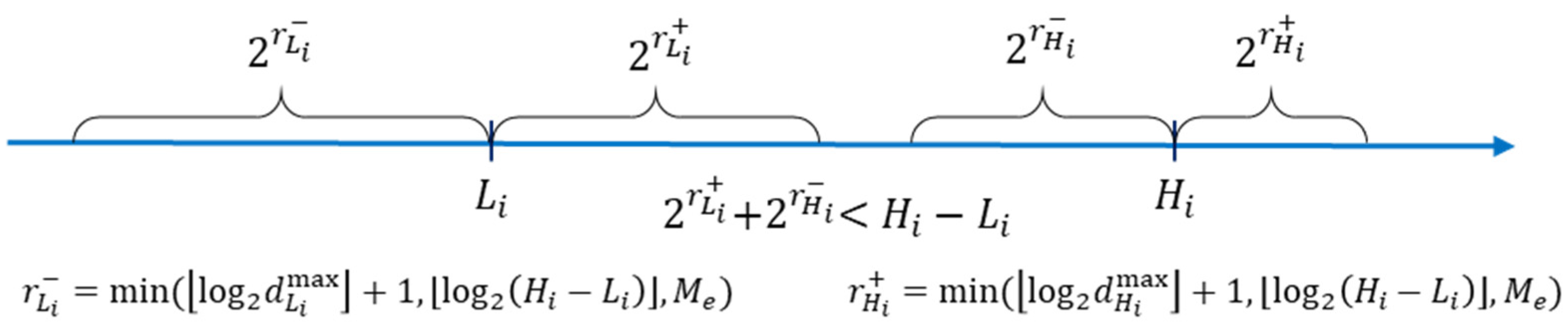
In the data embedding phase, the cover image is first divided into non-overlapping blocks , where denotes the total number of blocks. The pixel-level representation of the -th block is given by , where denotes the -th pixel of the -th block in the raster scan order. Its AMBTC-compressed code is denoted by , where is the bitmap. The reconstructed image block is denoted by , where is the -th block. When a block is determined to be embeddable, the secret data is embedded by modifying the reconstructed block into a stego block . Finally, the stego image is tiled up by the stego blocks and is denoted by . To maximize the data payload while preserving good image fidelity, a more sophisticated design of payloads for different situations is illustrated in Figure 2. During the embedding process, the payload of a cover pixel considers four cases, which are:
- (1)
- for and ,
- (2)
- for and ,
- (3)
- for and ,
- (4)
- for and .
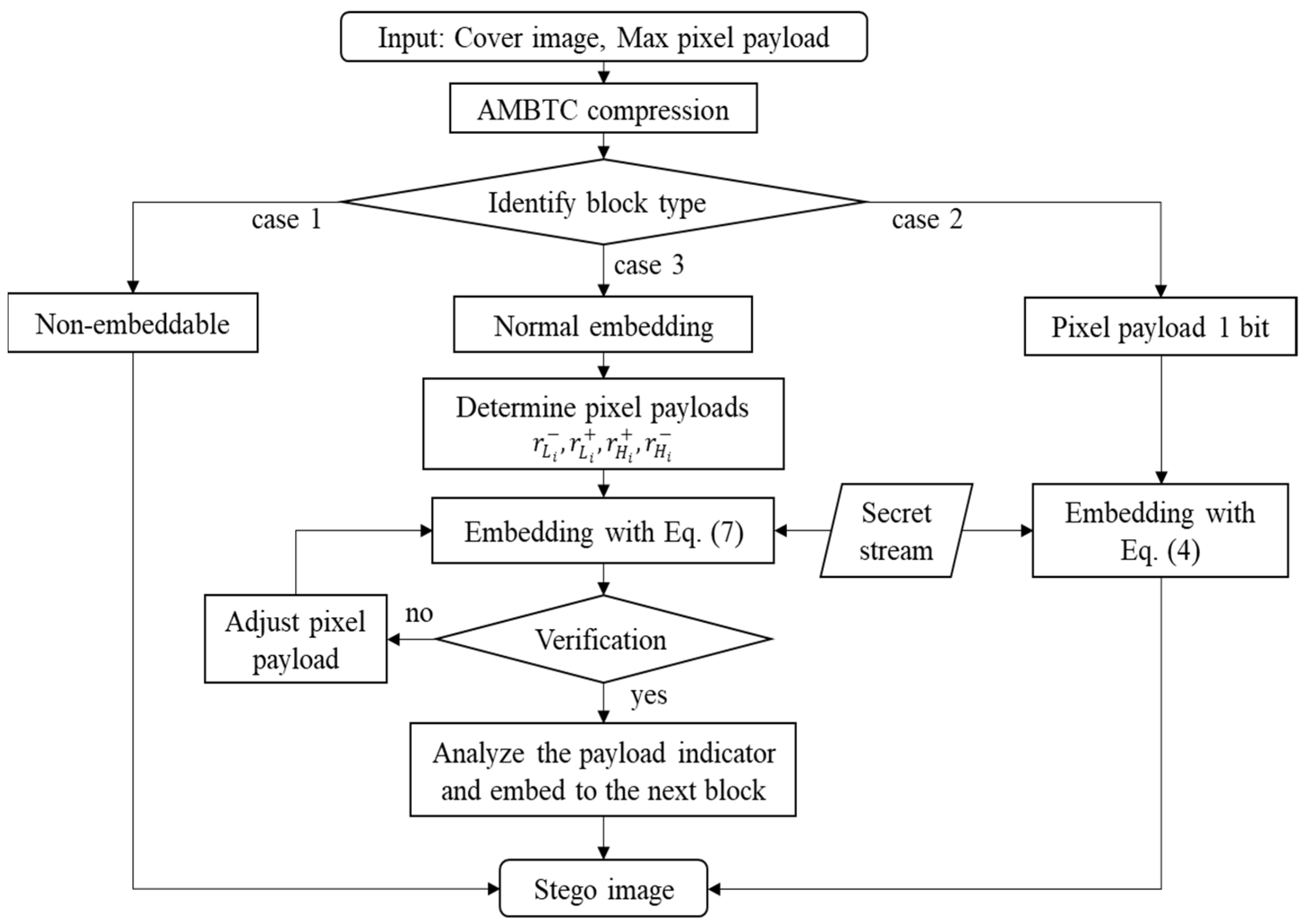
The symbol is defined by ; similarly, is defined by . The maximum allowed payload globally is constrained by . Thus, the modification of a pixel value is always toward its original value in the cover image. In addition, the payload for each case is determined according to the distribution of pixel values in the block. Based on these preliminaries, the flowchart of the data embedding phase is provided in Figure 3. The details are summarized in Algorithm 1.
| Algorithm 1. Data embedding algorithm |
| Input: Grayscale image , binary secret stream , maximum pixel payload . |
| Output: Stego image , where . |
| Step 1: Divide the cover image into blocks. For each block , apply AMBTC compression to obtain the compressed code and the reconstructed image block . Execute the following steps for each block. |
| Step 2: According to the values of and , this step considers three cases. Determine the payloads for different situations by: |
| and |
| , |
| where the maximum deviations and are defined by |
| and ; the symbol denotes the floor operation. |
| Case 1. or or . The current block is identified as non-embeddable, and the block process is finished. |
| Case 2. : If and , this block is an embeddable simple block. For an embeddable block, the first -valued and the first -valued pixels in are left unchanged. For the reset pixels, apply the following rule to embed one binary secret bit and finish the block process: |
| Case 3. : If and , this block is an embeddable complex block. Determine the payloads for different situations by and . To avoid overlapping of the inner embedding areas, an additional constraint is given by: |
| When the constraint of Equation (5) is not satisfied, or is decreased by 1 alternatively until satisfied. |
| Step 3: The first -valued and the first -valued pixels in are left unchanged. For each of the remaining pixels, determine its payload by: |
| Then, embed bits of secret data by: |
| Step 4: Verify the validity of the embedding result. First, the pixel values should be within the dynamic range of a grayscale image. Second, the rules for determining and should be valid. If , is determined by scanning to obtain the first that satisfies Equation (8); else, , is the first that satisfies Equation (9). |
| where and . |
| Step 5: If the determined by Equation (8) is not valid, is decreased by 1 and the process goes back to Step 3; if the determined by Equation (9) is not valid, is decreased by 1 and the process goes back to Step 3. If the verification is passed, record the stego block and proceed to the next step. |
| Step 6: Determine the payload indicator. The payloads for different cases are determined by the distribution of the cover pixel values. When recovering the payloads from a stego block, ambiguity may occur. After embedding, possible versions of payloads are fully searched, and a payload indicator is applied to denote the actual one. The initial estimation is given by the following equations: |
| where and . The full search subroutine is given as follows: |
| Subroutine 1: Payload Analyzer |
| . |
| For ( to ) { |
| For ( to ) { |
| For ( to ) { |
| For ( to ) { |
| If ( and and and |
| ) { |
| Record the payload set (,, , ), . } |
| }}}} |
| where denotes the number of pixels in the stego block that satisfy the condition. A payload indicator sized is used to indicate the actual payload set applied during embedding, where is the ceiling operation. This indicator is embedded into the next block. |
| Step 7: For the last embeddable block, the maximum pixel payload and payload indicator of its previous block are embedded with a fixed payload version given by Equation (4). |
An example of the data embedding process is illustrated in Figure 4. The original block is first compressed into the AMBTC format. The low mean and the high mean are valued at 181 and 221, respectively. Then, the initial values of payloads are calculated, and the secret bits are segmented accordingly. The first stego block generation attempt is given in the figure, where is not valid. Therefore, the payload is decreased by 1 and a new attempt is proceeded. After rearranging the secret bits and embedding, the final version of the stego block is generated.
3.2. Data Extraction and Image Recovery Phase
Upon receiving the stego image, it is first divided into blocks of size . Because the payload indicator of a block is embedded into its next block, the data extraction should process the blocks in reverse order. Thus, a stack data structure is applied. The stego blocks are checked in the raster scan order to obtain the embeddable blocks and are pushed into the waiting stack. Then, these blocks are popped out to extract the secret data. The detail of the data extraction and image recovery is given in Algorithm 2.
| Algorithm 2. Data extraction and image recovery algorithm |
| Input: Stego image . |
| Output: Binary secret stream , AMBTC-compressed image . |
| Step 1: For each stego block , calculate and . If |
| , this block is not embeddable. If , the quantization levels and should be identified first. The pixel is one of the two quantization levels. If , ; else, Then, apply Equations (8) and (9) to determine the second quantization level. If and , this block is embeddable and put into the waiting stack of blocks; else, it is not embeddable. |
| Step 2: Pop the top block out of the waiting stack. The obtained block corresponds to the last embeddable block of the stego image. The last embeddable block is embedded with only one secret bit for each embeddable pixel based on Equation (4). After excluding the first -valued and the first -valued pixels in , the secret bits can be extracted by: |
| The embedded data of the top block includes the maximum pixel payload , the payload indicator of , and secret bits. The first three bits record the value of to 6. If the quantization levels of satisfy , there is no payload indicator; else, the payload analyzer (Subroutine 1 in Algorithm 1) is applied to analyze the possible payload sets and determine the length of the payload indicator. After retrieving and , the remaining data are secret bits. The original pixel values can be restored by: |
| Step 3: For consecutively pop out the top block and process the block according to the following two possible cases. |
| Case 1. If , the embedded data are extracted by Equation (12), and the pixel values are restored by Equation (13) as the top block. Then, check the quantization levels of the next block and determine its payload indicator if necessary. |
| Case 2. If , apply the payload indicator retrieved from the previous block to obtain the pay load set (,, , ) of the block. Extract the embedded data using Equation (14) and restore the pixel values by using Equation (15). Note that the secret data should be converted back into binary format in its corresponding length of bits. Then, check quantization levels of the next block and determine its payload indicator if necessary. |
| Step 4: Combine the secret bits and restored image blocks into binary secret stream and AMBTC compressed image . The overall flowchart is shown in Figure 5. |
Figure 5.
The flowchart of data extraction and image recovery phase.

To demonstrate the key processing steps of the data extraction and image recovery phase, an example block is given in Figure 6. The two quantization levels and are determined first. Then, the initial estimation of payloads and are calculated. These parameters are sent to the payload analyzer, together with the maximum payload and the payload indicator . By applying Subroutine 1 in Algorithm 1, all possible solutions of payload set can be obtained. Only a few combinations can meet the four constraints checked by the analyzer. Therefore, the indicator is usually represented by just a few bits. For the given example, only six combinations of payload sets meet the constraints, and three bits are applied to record the indicator. If the indicator is , the first solution is the actual payload set. Accordingly, the embedded secret data and the cover pixel-values can be recovered using Equations (14) and (15).
4. Experimental Results
In this section, the performance of the proposed scheme is evaluated and compared with state-of-the-art methods. In addition, the security of our scheme under steganalysis is also assessed. We took eight test images from the USC-SIPI Image Database [43], namely, ‘Lena’, ‘Airplane’, ‘Zelda’, ‘Boat’, ‘Baboon’, ‘Peppers’, ‘House’, and ‘Couple’, which are shown in Figure 7. In addition, our scheme was applied to 10,000 images in the BOWS2 dataset [44]. The platform for conducting the experiments was a PC with an Intel®® Core™ i7-8750H CPU @ 2.20 GHz and 16 GB RAM with MATLAB R2014b. The secret bits were randomly generated. The embedding capacity (EC) and peak signal to noise radio (PSNR) were used to evaluate the performance of our proposed scheme. The visual quality of the images denoted by PSNR is defined by:
where and represent the pixel value of the cover image and the stego image, respectively; the constants and are the width and the height of the cover image, respectively.
4.1. Performance of the Proposed Scheme
To assess the performance of our scheme under different maximum payload settings, we applied the maximum payload of 2 bits to 6 bits. All experimental data for the eight test images are listed in Table 1. The first row is the PSNR values of the AMBTC compressed images with respect to their original cover images. It is a common principle that the PSNR value of a compressed image is lower when the texture of the original image is more complex. The image ‘Baboon’ is the most complex image among the eight test samples, and therefore the PSNR value of its AMBTC compressed image is the lowest. For each maximum payload value, we list the PSNR, the total embedding capacity , and the amount of auxiliary information required to record the payload indicators, where and are measured in total number of bits for a test image. The net data embedding capacity of an image can be calculated by subtracting from . As shown in the table, the PSNR value of the stego images increases with increasing payload and reaches a maximum at 3 bits or 4 bits. Further increasing the maximum payload degrades the visual quality of the stego images. Among the eight test images, the total embedding capacity of the image ‘Baboon’ is the highest, which is a notably different result from those of the current existing data hiding methods.
The executions time required for all test images under different maximum allowed payloads are listed in Table 2. Because the optimal for most test images is 4 bits, the practical execution time can be seen in the row of . The typical execution time of the proposed scheme is within 10 sec.
4.2. Comparison with Related Works
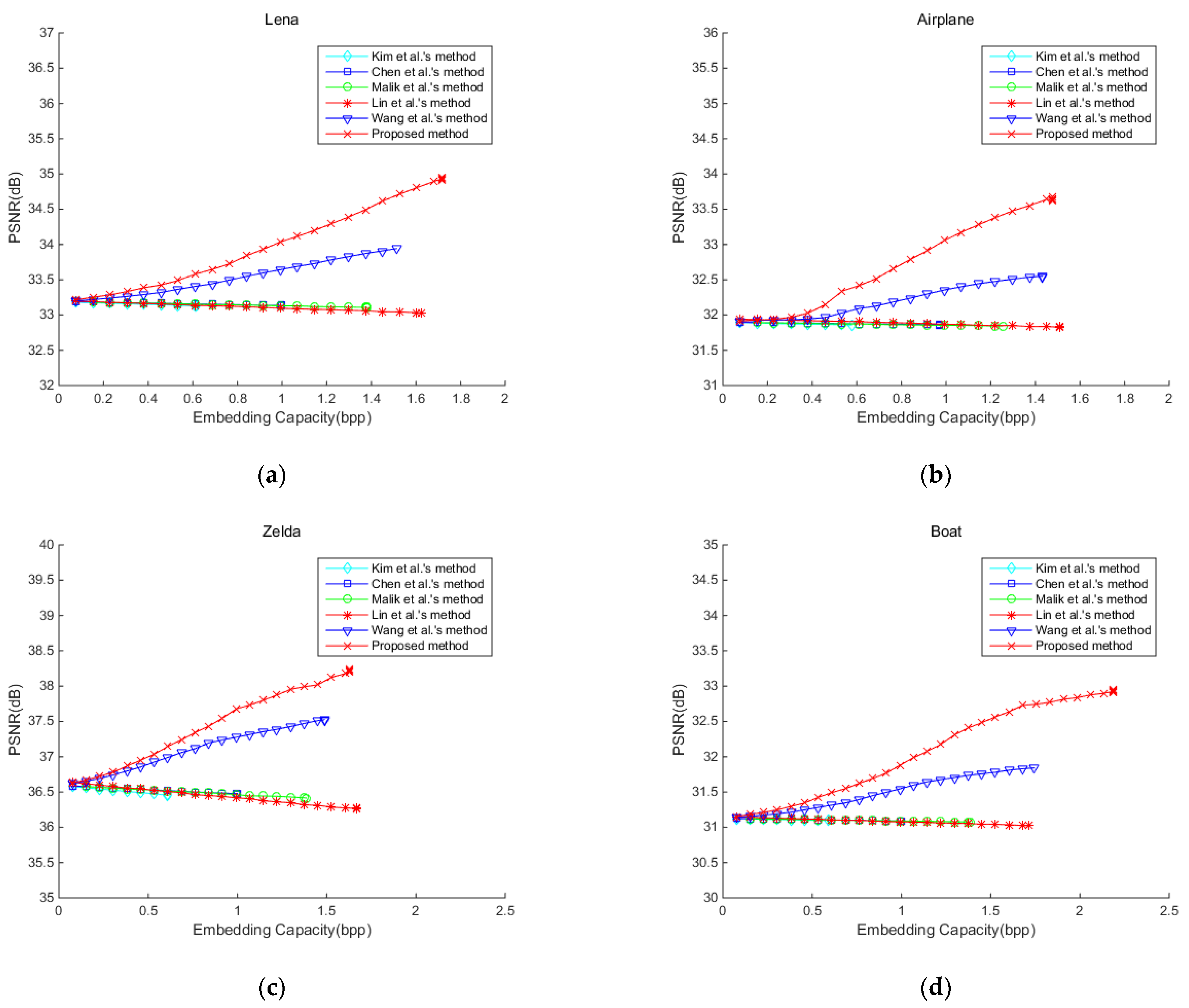
The performance of our scheme was compared with five existing AMBTC-based data hiding methods, namely, those of Wang et al. [42], Lin et al. [40], Malik et al. [33], Chen et al. [38], and Kim et al. [39]. Table 3 lists the PSNR and embedding capacity for the eight test images, where the maximum payload setting of our scheme is . Referring to the PSNR values of AMBTC compressed images provided in Table 1, the PSNR values of the methods of Lin et al. [40], Malik et al. [33], Chen et al. [38], and Kim et al. [39] slightly degrade after embedding. Only the proposed scheme and Wang et al.’s method [42] improved the PSNR value after embedding. Further, the proposed scheme outperformed the related works both in embedding capacity and visual quality. The evolution of PSNR value with increasing payload are plotted in Figure 8, where for our scheme. As the number of utilized blocks increases with the payload, the PSNR value increases. The proposed scheme is based on the AMBTC compressed version of an image block. The modification of the pixel value due to embedding is always toward the original pixel value. Therefore, the visual quality of the stego image is better than the AMBTC compressed version.
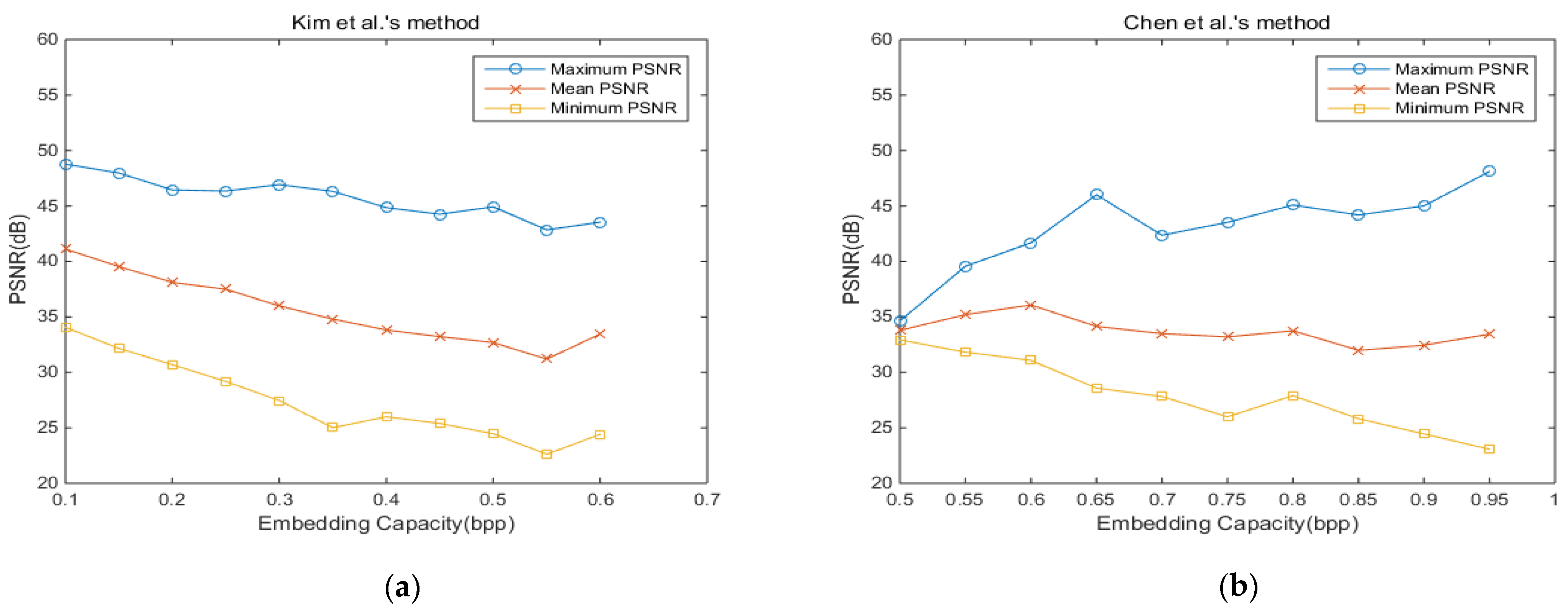
To further investigate the generalizability of the related works, the BOW2 dataset [44], which consists of 10,000 test images, was applied. For each of the related methods, we plot the envelope of PSNR values with respect to embedding capacity in Figure 9; that is, we fully embedded each test image to determine its PSNR value. Then, the PSNR values of all test images were quantized into equally spaced values. For each quantized PSNR value, we plot the maximum, minimum, and mean values within its corresponding category. For each method, the average values of EC and PSNR for 10,000 test images are listed below the figure. As shown in the figure, the proposed scheme outperformed the related works both in average EC and in average PSNR value. Some of the test images in the dataset can be embedded with more than 3 bpp, which is much greater than the compared methods.
4.3. Steganalysis
To estimate the security level of the stego images generated by our proposed scheme, RS steganalysis [45] was applied. In the RS steganalysis, we first divided the image into non-overlapping blocks. Then, a discrimination function f, a flipping function F, and a mask M = [0 1; 1 0] were defined to obtain three types of pixel blocks: regular blocks, singular blocks, and unusable blocks. The percentages of regular and singular blocks for mask M are denoted by RM and SM. When the mask is −M, the values R−M and S−M can be obtained similarly. A secure stego image should have its RM very close to R−M and SM very close to S−M. To make it easier to observe the overall performance, we defined the index p by combining the two absolute differences as:
The value of p can be treated as the percentage deviation with respect to its absolute value; when p is less than five percent (0.05) the stego image is less likely to be suspected. Table 4 lists the RS steganalysis results of the related works. As shown in the table, the p values of all methods are small enough such that the stego images can be treated as secure. The best performances achieved among the six methods for all test images are highlighted with bold figures.
Another commonly applied steganalysis technique is the pixel value differencing histogram (PDH) analysis proposed by Zhang and Wang [46], which is applied to detect the pixel value differencing (PVD)-based data hiding. When secret data is embedded by PVD, the pairwise difference of pixels is expanded and the peak in PDH is degraded. The PDH analysis of the proposed scheme for the practical parameter of is given in Figure 10, where the PDH of stego images still preserves a significant peak. Of course, the degradation of peak value is proportional to the amount of embedded data.
5. Conclusions
This paper proposed an RDH scheme for AMBTC-compressed images with an adaptive bitrate. The data embedding for each image block is based on the AMBTC-compressed version. Each pixel value of an AMBTC block is compared with its corresponding pixel value in the original block. The embedding process always modifies the pixel value toward the original value with a bitrate proportional to the gap width. Therefore, the proposed scheme can produce a stego image with a better visual quality than the AMBTC-compressed version. The proposed scheme outperforms state-of-the-art methods both in visual quality of the stego images and the embedding capacity of secret data. The resulting stego images were tested by RS steganalysis, and the experimental data proves the high security level of the proposed scheme.
Digital images in compressed formats are more applicable than conventional bitmap images. Development of RDH schemes for compressed digital images is a promising research topic and more application fields will be found.
Author Contributions
Conceptualization, C.-C.C.; Data curation, J.L.; Formal analysis, J.L.; Funding acquisition, J.L.; Methodology, J.L. and J.-H.H.; Project administration, C.-C.C.; Supervision, C.-C.C.; Validation, J.-H.H.; Visualization, J.-H.H.; Writing—original draft, J.L.; Writing—review & editing, J.-H.H. All authors have read and agreed to the published version of the manuscript.
Funding
This work was supported in part by the Natural Science Foundation of Fujian Province under Grant 2021J011236, and in part by the Education and Scientific Research Foundation of Fujian Province under Grant JA15575.
Institutional Review Board Statement
Not applicable.
Informed Consent Statement
Not applicable.
Data Availability Statement
Not applicable.
Conflicts of Interest
The authors declare no conflict of interest.
References
- Li, S.; Leung, K.; Cheng, L.M.; Chan, C.K. A novel image-hiding scheme based on block difference. Pattern Recognit. 2006, 39, 1168–1176. [Google Scholar] [CrossRef]
- Hong, W.; Chen, T.S.; Chen, J. Reversible data hiding using delaunay triangulation and selective embedment. Inf. Sci. 2015, 308, 140–154. [Google Scholar] [CrossRef]
- Chan, C.K.; Cheng, L.M. Hiding data in images by simple lsb substitution. Pattern Recognit. 2004, 37, 469–474. [Google Scholar] [CrossRef]
- Wu, D.C.; Tsai, W.H. A steganographic method for images by pixel value differencing. Pattern Recogn. Lett. 2003, 24, 1613–1626, 2003. [Google Scholar] [CrossRef]
- Zhang, D.X.; Pan, Z.; Li, H. A contour-based semi-fragile image watermarking algorithm in dwt domain. In Proceedings of the Second International Workshop on Education Technology and Computer Science, Wuhan, China, 6–7 March 2010; Volume 3, pp. 228–231. [Google Scholar]
- Wu, X.; Sun, W. Robust copyright protection scheme for digital images using overlapping DCT and SVD. Appl. Soft Comput. 2013, 13, 1170–1182. [Google Scholar] [CrossRef]
- Gray, R.M. Vector quantization. IEEE Assp. Mag. 1984, 1, 4–29. [Google Scholar] [CrossRef]
- Kim, T. Side match and overlap match vector quantizers for images. IEEE Trans. Image Process. 1992, 1, 170–185. [Google Scholar] [CrossRef] [PubMed]
- Wang, K.; Lu, Z.M.; Hu, Y.J. A high capacity lossless data hiding scheme for jpeg images. J Syst. Softw. 2013, 86, 1965–1975. [Google Scholar] [CrossRef]
- Delp, E.J.; Mitchell, O.R. Image compression using block truncation coding. IEEE Trans. Commun. 1979, 27, 1335–1342. [Google Scholar] [CrossRef]
- Lema, M.; Mitchell, O. Absolute moment block truncation coding and its application to color images. IEEE Trans. Commun. 1984, 32, 1148–1157. [Google Scholar] [CrossRef]
- Kumar, R.; Kim, D.S.; Jung, K.H. Enhanced AMBTC based data hiding method using hamming distance and pixel value differencing. J. Inf. Secur. Appl. 2019, 47, 94–103. [Google Scholar] [CrossRef]
- Kumar, R.; Jung, K. A systematic survey on block truncation coding based data hiding techniques. Multimed. Tools Appl. 2019, 78, 32239–32259. [Google Scholar] [CrossRef]
- Li, C.H.; Lu, Z.M.; Su, Y.X. Reversible data hiding for btc-compressed images based on bitplane flipping and histogram shifting of mean tables. Inf. Technol. J. 2011, 10, 1421–1426. [Google Scholar] [CrossRef] [Green Version]
- Lin, C.; Liu, X. A reversible data hiding scheme for block truncation compressions based on histogram modification. In Proceedings of the 2012 Sixth International Conference on Genetic and Evolutionary Computing, Washington, DC, USA, 25–28 August 2012; pp. 157–160. [Google Scholar]
- Chang, C.I.; Hu, C.Y.; Chen, L.W.; Lu, C.C. High capacity reversible data hiding scheme based on residual histogram shifting for block truncation coding. Signal Process. 2015, 108, 376–388. [Google Scholar] [CrossRef]
- Li, F.; Bharanitharan, K.; Chang, C.C.; Mao, Q. Bi-stretch reversible data hiding algorithm for absolute moment block truncation coding compressed images. Multimed. Tools Appl. 2016, 75, 16153–16171. [Google Scholar] [CrossRef]
- Lin, C.C.; Chang, C.C.; Wang, Z.M. Reversible data hiding scheme using adaptive block truncation coding based on an edge-based quantization approach. Symmetry 2019, 11, 765. [Google Scholar] [CrossRef] [Green Version]
- Wang, K.; Hu, Y.; Lu, Z. Reversible data hiding for block truncation coding compressed images based on prediction-error expansion. In Proceedings of the 2012 Eighth International Conference on Intelligent Information Hiding and Multimedia Signal Processing, Washington, DC, USA, 18–20 July 2012; pp. 317–320. [Google Scholar]
- Sun, W.; Lu, Z.M.; Wen, Y.C.; Yu, F.X.; Shen, R.J. High performance reversible data hiding for block truncation coding compressed images. Signal. Image Video Process. 2013, 7, 297–306. [Google Scholar] [CrossRef]
- Hong, W.; Ma, Y.B.; Wu, H.C. An efficient reversible data hiding method for AMBTC compressed images. Multimed. Tools Appl. 2017, 76, 5441–5460. [Google Scholar] [CrossRef]
- Tsai, Y.Y.; Chan, C.S.; Liu, C.L.; Su, B.R. A reversible steganographic algorithm for btc-compressed images based on difference expansion and median edge detector. Imaging Sci. J. 2014, 62, 48–55. [Google Scholar] [CrossRef]
- Chang, C.C.; Chen, T.S.; Wang, Y.K.; Liu, Y.J. A reversible data hiding scheme based on absolute moment block truncation coding compression using exclusive or operator. Multimed. Tools Appl. 2018, 77, 9039–9053. [Google Scholar] [CrossRef]
- Hong, W. Efficient data hiding based on block truncation coding using pixel pair matching technique. Symmetry 2018, 10, 36. [Google Scholar] [CrossRef] [Green Version]
- Hong, W.; Zhou, X.Y.; Weng, S.W. Joint adaptive coding and reversible data hiding for AMBTC compressed images. Symmetry 2018, 10, 254. [Google Scholar] [CrossRef] [Green Version]
- Chuang, J.-C.; Chang, C.-C. Using a simple and fast image compression algorithm to hide secret information. Int. J. Comput. App. 2006, 28, 1735–1743. [Google Scholar]
- Ou, D.; Sun, W. High payload image steganography with minimum distortion based on absolute moment block truncation coding. Multimed. Tools Appl. 2015, 74, 9117–9139. [Google Scholar] [CrossRef]
- Huang, Y.H.; Chang, C.C.; Chen, Y.H. Hybrid secret hiding schemes based on absolute moment block truncation coding. Multimed. Tools Appl. 2017, 76, 6159–6174. [Google Scholar] [CrossRef]
- Chen, Y.Y.; Chi, K.Y. Cloud image watermarking: High quality data hiding and blind decoding scheme based on block truncation coding. Multimed. Tools Appl. 2017, 25, 1–13. [Google Scholar] [CrossRef]
- Kumar, R.; Kumar, N.; Jung, K. A New Data Hiding Method Using Adaptive & Quantization Dynamic Bit Plane Based AMBTC. In Proceedings of the 2019 6th International Conference on Signal Processing and Integrated Networks (SPIN), Noida, India, 7–8 March 2019; pp. 854–858. [Google Scholar]
- Lin, C.C.; Liu, X.L.; Tai, W.L.; Yuan, S.M. A novel reversible data hiding scheme based on AMBTC compression technique. Multimed. Tools Appl. 2015, 74, 3823–3842. [Google Scholar] [CrossRef]
- Pan, J.; Li, W.; Lin, C.C. Novel reversible data hiding scheme for AMBTC-compressed images by reference matrix. In Proceedings of the MISNC 2014, Kaohsiung, Taiwan, 13–14 September 2014; pp. 427–436. [Google Scholar]
- Malik, A.; Sikka, G.; Verma, H.K. An AMBTC compression based data hiding scheme using pixel value adjusting strategy. Multidim. Syst. Sign. Process. 2018, 4, 1801–1818. [Google Scholar] [CrossRef]
- Chang, C.C.; Liu, Y.J.; Nguyen, S.T. A novel data hiding scheme for block truncation coding compressed images using dynamic programming strategy. In Proceedings of the Sixth International Conference on Graphic and Image Processing (ICGIP 2014), Beijing, China, 24–26 October 2014. [Google Scholar]
- Lin, J.; Lin, C.C.; Chang, C.C. Reversible steganographic scheme for AMBTC-compressed image based on (7, 4) hamming code. Symmetry 2019, 11, 1236–1252. [Google Scholar]
- Lo, C.C.; Hu, Y.C.; Chen, W.L.; Wu, C.M. Reversible data hiding scheme for btc-compressed images based on histogram shifting. Int. J. Secur. Its Appl. 2014, 8, 201–314. [Google Scholar] [CrossRef]
- Ni, Z.; Shi, Y.Q.; Ansari, N.; Su, W. Reversible data hiding. IEEE Trans. Circuits Syst. Video Technol. 2006, 16, 354–362. [Google Scholar]
- Chen, Y.-Y.; Hsia, C.-H.; Jhong, S.Y.; Lin, H.-J. Data hiding method for AMBTC compressed images. J. Ambient Intell. Humaniz. Comput. 2018, 12, 1–9. [Google Scholar] [CrossRef]
- Kim, C.; Shin, D.; Leng, L.; Yang, C.-N. Lossless data hiding for absolute moment block truncation coding using histogram modification. J. Real Time Image Process. 2016, 14, 101–114. [Google Scholar] [CrossRef]
- Lin, J.; Weng, S.; Zhang, T.; Ou, B.; Chang, C.C. Two-layer reversible data hiding based on AMBTC image with (7, 4) hamming code. IEEE Access 2020, 8, 21534–21548. [Google Scholar] [CrossRef]
- Lin, C.-C.; Nguyen, T.-S.; Chang, C.-C.; Chang, W.-C. Efficient Reversible Data Hiding Scheme for AMBTC-Compressed Images. Appl. Sci. 2021, 11, 6741. [Google Scholar] [CrossRef]
- Wang, X.; Chang, C.C.; Lin, C.C. Adaptive reversible data hiding scheme for AMBTC compressed images. Multimed. Tools Appl. 2019, 78, 1–22. [Google Scholar] [CrossRef]
- The USC-SIPI Image Database. Available online: http//sipi.usc.edu/database (accessed on 3 December 2021).
- The bows2 Image Database. Available online: http://bows2.ec-lille.fr/ (accessed on 3 December 2021).
- Fridrich, J.; Goljan, M. Practical steganalysis of digital images—State of the art. Proc. SPIE 2002, 4675, 1–13. [Google Scholar]
- Zhang, X.; Wang, S. Vulnerability of pixel-value differencing steganography to histogram analysis and modification for enhanced security. Pattern Recognit. Lett. 2004, 3, 331–339. [Google Scholar] [CrossRef]
Figure 1.
AMBTC compression of an example image block.

Figure 2.
Illustration of the asymmetric payloads for different situations.

Figure 3.
Flowchart of the data embedding phase.

Figure 4.
An example block of the data embedding phase.

Figure 6.
An example block of the data extraction and image recovery phase.

Figure 7.
Eight test images from USC-SIPI Image Database. (a) Lena; (b) Airplane; (c) Zelda; (d) Boat. (e) Baboon; (f) Peppers; (g) House; (h) Couple.
Figure 7.
Eight test images from USC-SIPI Image Database. (a) Lena; (b) Airplane; (c) Zelda; (d) Boat. (e) Baboon; (f) Peppers; (g) House; (h) Couple.

Figure 8.
PSNR value under different payloads for the eight test images. (a) Lena; (b) Airplane; (c) Zelda; (d) Boat; (e) Baboon; (f) Peppers; (g) House; (h) Couple.
Figure 8.
PSNR value under different payloads for the eight test images. (a) Lena; (b) Airplane; (c) Zelda; (d) Boat; (e) Baboon; (f) Peppers; (g) House; (h) Couple.


Figure 9.
PSNR value under different payloads for the BOWS2 dataset. (a) ; (b) ; (c) ; (d) ; (e) ; (f) .
Figure 9.
PSNR value under different payloads for the BOWS2 dataset. (a) ; (b) ; (c) ; (d) ; (e) ; (f) .


Figure 10.
The PDH analysis of the proposed RDH scheme for . (a) Lena; (b) Airplane; (c) Zelda; (d) Boat; (e) Baboon; (f) Peppers; (g) House; (h) Couple.
Figure 10.
The PDH analysis of the proposed RDH scheme for . (a) Lena; (b) Airplane; (c) Zelda; (d) Boat; (e) Baboon; (f) Peppers; (g) House; (h) Couple.


Table 1.
Performance of the proposed scheme under different maximum payload settings.
| Index | Lena | Airplane | Zelda | Boat | Baboon | Peppers | House | Couple | |
|---|---|---|---|---|---|---|---|---|---|
| AMBTC | 33.20 | 31.95 | 36.65 | 31.15 | 26.98 | 33.39 | 30.97 | 31.25 | |
| 2 bits | 34.00 | 32.53 | 37.80 | 31.89 | 27.62 | 34.16 | 31.67 | 32.01 | |
| 337,288 | 269,619 | 352,196 | 405,711 | 449,879 | 373,508 | 327,067 | 407,157 | ||
| 8284 | 7124 | 7541 | 12,008 | 15,812 | 9167 | 10,412 | 12,449 | ||
| 3 bits | 34.55 | 33.10 | 38.26 | 32.50 | 28.31 | 34.68 | 34.68 | 32.65 | |
| 412,628 | 339,543 | 408,053 | 518,738 | 636,204 | 445,277 | 438,344 | 527,937 | ||
| 5986 | 6182 | 4781 | 8407 | 13,255 | 6238 | 9454 | 9670 | ||
| 4 bits | 34.94 | 33.64 | 38.23 | 32.93 | 29.04 | 35.01 | 32.91 | 33.01 | |
| 448,478 | 379,679 | 425,999 | 572,612 | 769,462 | 473,714 | 502,890 | 584,645 | ||
| 4949 | 6244 | 3878 | 6889 | 10,869 | 6035 | 8594 | 9059 | ||
| 5 bits | 34.67 | 33.55 | 37.93 | 32.65 | 28.77 | 34.70 | 32.60 | 32.68 | |
| 459,152 | 396,503 | 428,531 | 589,454 | 830,456 | 477,889 | 524,053 | 596,546 | ||
| 4775 | 6304 | 3841 | 6548 | 7809 | 6329 | 8173 | 9558 | ||
| 6 bits | 34.43 | 33.07 | 37.95 | 32.36 | 28.40 | 34.41 | 32.37 | 32.39 | |
| 457,000 | 393,257 | 428,578 | 585,323 | 831,316 | 473,162 | 521,128 | 590,635 | ||
| 4970 | 5916 | 3843 | 7040 | 8084 | 6051 | 7902 | 9884 |
Table 2.
Execution time of the proposed RDH scheme under different maximum payloads.
| Time (S) | Lena | Airplane | Zelda | Boat | Baboon | Peppers | House | Couple |
|---|---|---|---|---|---|---|---|---|
| = 2 | 5.501 | 5.363 | 5.618 | 5.558 | 5.629 | 5.589 | 5.198 | 5.575 |
| = 3 | 6.465 | 5.988 | 6.568 | 6.138 | 5.797 | 6.456 | 5.901 | 6.153 |
| = 4 | 9.105 | 8.184 | 9.486 | 7.998 | 6.419 | 8.938 | 7.213 | 7.966 |
| = 5 | 15.236 | 13.134 | 16.213 | 12.587 | 8.575 | 15.187 | 10.990 | 12.578 |
| = 6 | 27.096 | 22.697 | 30.088 | 23.522 | 14.200 | 27.176 | 18.690 | 22.273 |
Table 3.
Comparison with related works.
| Method | Factor | Lena | Airplane | Zelda | Boat | Baboon | Peppers | House | Couple |
|---|---|---|---|---|---|---|---|---|---|
| Proposed (Me = 4 bit) | PSNR (dB) | 34.94 | 33.64 | 38.23 | 32.93 | 29.04 | 35.01 | 32.91 | 33.01 |
| (bits) | 443,529 | 373,435 | 422,121 | 565,723 | 758,593 | 467,679 | 494,296 | 575,586 | |
| Wang et al.’s method [42] | PSNR (dB) | 33.94 | 32.54 | 37.53 | 31.84 | 27.63 | 34.08 | 31.65 | 31.95 |
| (bits) | 396,751 | 375,342 | 389,829 | 457,180 | 540,770 | 415,660 | 429,914 | 465,444 | |
| Lin et al.’s method [40] | PSNR (dB) | 33.03 | 31.83 | 36.26 | 31.02 | 26.93 | 33.19 | 30.87 | 31.13 |
| (bits) | 426,246 | 395,638 | 436,735 | 448,606 | 458,077 | 442,876 | 412,315 | 449,560 | |
| Malik et al.’s method [33] | PSNR (dB) | 33.10 | 31.84 | 36.41 | 31.07 | 26.96 | 33.26 | 30.88 | 31.15 |
| (bits) | 362,088 | 328,981 | 363,397 | 362,754 | 363,419 | 363,441 | 310,054 | 363,508 | |
| Chen et al.’s method [38] | PSNR (dB) | 33.14 | 31.86 | 36.48 | 31.09 | 26.96 | 33.29 | 30.89 | 31.17 |
| (bits) | 262,000 | 254,178 | 262,144 | 262,065 | 262,144 | 262,144 | 241,072 | 262,129 | |
| Kim et al.’s method [39] | PSNR (dB) | 33.13 | 31.86 | 36.46 | 31.10 | 26.97 | 33.29 | 30.90 | 31.18 |
| (bits) | 161,485 | 151,266 | 159,270 | 155,491 | 151,293 | 159,416 | 134,569 | 156,431 |
Table 4.
Comparison under RS steganalysis.
| Methods | Lena | Airplane | Zelda | Boat | Baboon | Peppers | House | Couple | Average | |
|---|---|---|---|---|---|---|---|---|---|---|
| Proposed | 0.6418 | 0.7186 | 0.6484 | 0.5645 | 0.4997 | 0.6204 | 0.6590 | 0.6978 | ||
| 0.6440 | 0.7210 | 0.6396 | 0.5649 | 0.4948 | 0.6264 | 0.6586 | 0.6911 | |||
| 0.2375 | 0.1817 | 0.2263 | 0.3032 | 0.3715 | 0.2553 | 0.2352 | 0.1976 | |||
| 0.2405 | 0.1815 | 0.2368 | 0.3022 | 0.3724 | 0.2481 | 0.2330 | 0.2018 | |||
| 0.0060 | 0.0029 | 0.0220 | 0.0016 | 0.0067 | 0.0151 | 0.0029 | 0.0082 | 0.0083 | ||
| Malik et al.’s method [33] | 0.7145 | 0.7663 | 0.7095 | 0.6737 | 0.6378 | 0.7167 | 0.7431 | 0.7223 | ||
| 0.7123 | 0.7593 | 0.7082 | 0.6850 | 0.6390 | 0.6973 | 0.7480 | 0.7217 | |||
| 0.1788 | 0.1404 | 0.1787 | 0.2068 | 0.2393 | 0.1800 | 0.1573 | 0.1756 | |||
| 0.1767 | 0.1465 | 0.1785 | 0.2040 | 0.2422 | 0.1867 | 0.1577 | 0.1744 | |||
| 0.0050 | 0.0144 | 0.0017 | 0.0160 | 0.0046 | 0.0291 | 0.0058 | 0.0089 | 0.0101 | ||
| Kim et al.’s method [39] | 0.8090 | 0.8502 | 0.8175 | 0.7939 | 0.7552 | 0.8154 | 0.8358 | 0.8154 | ||
| 0.8114 | 0.8533 | 0.8201 | 0.7850 | 0.7545 | 0.8212 | 0.8416 | 0.8180 | |||
| 0.1071 | 0.0810 | 0.0987 | 0.1217 | 0.1547 | 0.1034 | 0.0948 | 0.1071 | |||
| 0.1047 | 0.0803 | 0.0996 | 0.1225 | 0.1509 | 0.1019 | 0.0882 | 0.1072 | |||
| 0.0053 | 0.0040 | 0.0038 | 0.0106 | 0.0050 | 0.0079 | 0.0133 | 0.0021 | 0.0059 | ||
| Chen et al.’s method [38] | 0.6056 | 0.6658 | 0.5969 | 0.5469 | 0.4841 | 0.5846 | 0.6313 | 0.6410 | ||
| 0.5922 | 0.6672 | 0.6058 | 0.5398 | 0.4836 | 0.5928 | 0.6287 | 0.6459 | |||
| 0.2572 | 0.2144 | 0.2675 | 0.3150 | 0.3810 | 0.2770 | 0.2467 | 0.2436 | |||
| 0.2661 | 0.2197 | 0.2582 | 0.3205 | 0.3772 | 0.2724 | 0.2505 | 0.2443 | |||
| 0.0259 | 0.0075 | 0.0211 | 0.0146 | 0.0049 | 0.0150 | 0.0073 | 0.0406 | 0.0157 | ||
| Lin et al.’s method [40] | 0.6808 | 0.7129 | 0.6844 | 0.6535 | 0.6242 | 0.6768 | 0.6946 | 0.6884 | ||
| 0.6777 | 0.7077 | 0.6768 | 0.6570 | 0.6077 | 0.6802 | 0.6825 | 0.6926 | |||
| 0.2069 | 0.1792 | 0.1999 | 0.2303 | 0.2555 | 0.2141 | 0.1994 | 0.2018 | |||
| 0.2096 | 0.1850 | 0.2076 | 0.2228 | 0.2740 | 0.2079 | 0.2062 | 0.2000 | |||
| 0.0065 | 0.0122 | 0.0174 | 0.0125 | 0.0397 | 0.0109 | 0.0212 | 0.0131 | 0.0147 | ||
| Wang et al.’s method [42] | 0.7279 | 0.7676 | 0.7203 | 0.6792 | 0.6142 | 0.7211 | 0.7234 | 0.7464 | ||
| 0.7268 | 0.7609 | 0.7274 | 0.6768 | 0.6243 | 0.7211 | 0.7240 | 0.7387 | |||
| 0.1673 | 0.1438 | 0.1690 | 0.2071 | 0.2653 | 0.1746 | 0.1735 | 0.1576 | |||
| 0.1710 | 0.1465 | 0.1658 | 0.2127 | 0.2578 | 0.1728 | 0.1763 | 0.1632 | |||
| 0.0053 | 0.0103 | 0.0116 | 0.0090 | 0.0201 | 0.0020 | 0.0038 | 0.0072 | 0.0096 |
Publisher’s Note: MDPI stays neutral with regard to jurisdictional claims in published maps and institutional affiliations. |
© 2021 by the authors. Licensee MDPI, Basel, Switzerland. This article is an open access article distributed under the terms and conditions of the Creative Commons Attribution (CC BY) license (https://creativecommons.org/licenses/by/4.0/).
Share and Cite
MDPI and ACS Style
Lin, J.; Chang, C.-C.; Horng, J.-H. Asymmetric Data Hiding for Compressed Images with High Payload and Reversibility. Symmetry 2021, 13, 2355. https://0-doi-org.brum.beds.ac.uk/10.3390/sym13122355
AMA Style
Lin J, Chang C-C, Horng J-H. Asymmetric Data Hiding for Compressed Images with High Payload and Reversibility. Symmetry. 2021; 13(12):2355. https://0-doi-org.brum.beds.ac.uk/10.3390/sym13122355
Chicago/Turabian StyleLin, Juan, Chin-Chen Chang, and Ji-Hwei Horng. 2021. "Asymmetric Data Hiding for Compressed Images with High Payload and Reversibility" Symmetry 13, no. 12: 2355. https://0-doi-org.brum.beds.ac.uk/10.3390/sym13122355
Note that from the first issue of 2016, this journal uses article numbers instead of page numbers. See further details here.