1. Introduction
The intended use of the inertial platform studied in the paper is to host an advanced 10 MeV Gamma ray source, developed within the framework of the ELI-NP project. This project was funded by the European Commission in order to build a research facility at the Magurele site (Romania) and involves the construction of a center for exploring the advanced scientific potential of a high intensity laser system (up to 1024 W/cm2). In addition, a high-brightness Gamma beam system will be explored. The success of this project can advance the available technologies by at least 2 orders of magnitude as compared to the current state of the art. Thus, applications and studies of nuclear physics, which cannot be carried out at the moment, could be realized successfully with the gamma beam system.
ELI-NP (Extreme Light Infrastructure-Nuclear Physics) is an important project that brings together 13 European countries to achieve a shared goal. In this study, the vibration behavior of the inertial platform of the project related to the building that will host the installations is conducted. The project involves the achievement of the following two objectives: a very high intensity laser system (10–30 PW) and a very bright γ beam, intense up to 19 MeV, 0.1% bandwidth and 1013 γ/s. The gamma beam system to be built for ELI-NP, Magurele Bucharest, must offer a very bright photon beam, with a wide bandwidth and adjustability. Its realization and possible applications are presented in the WhiteBook [
1] of the ELI-NP project and in the Technical Design Reports [
2].
The major development directions in major experimental research are presented in [
3,
4] in the study of nuclear resonance fluorescence (NRF) and the study of conditions above the neutron emission threshold. The gamma source from ELI-NP can ensure the success of such experiments due to the small size of the beam and the possibility of its very precise positioning. In order to achieve this positioning, it is necessary to achieve good insulation and a significantly reduced transmission of anthropogenetic and natural vibrations to the platform on which the laser and gamma systems are positioned. The platform represents unique engineering achievements in both its dimensions and by the spectacular results obtained in the design and study of this structure. This experience can be used for future projects.
The reduction in the transmission of vibrations from the outside of the building to the platform was achieved by isolating the platform that is placed on boxes of elastic springs and shock absorbers. The reduction in vibration transmissions from one laboratory unit to the other devices on the platform should also be considered. The first study in the field of insulation of such a platform was performed in the middle of the last century [
5,
6]. Numerous insulation solutions that depend on mounting spring systems have been proposed over the years with the aim of reducing the vibrations of anthropogenic sources. Supports for heavy objects are constructed using metal springs or rubber elements, which also provide damping [
7]. A more accurate modeling of the system becomes necessary to choose the optimal solution with the lowest costs.
These projects are rarely encountered in practice, so the results obtained are important in the context of similar constructions.
The inertial platform can be considered as rigid with six degrees of freedom (Steward platform). There are numerous studies for such systems. Several methods to isolate such a system exist, and are controlled by a variety of parameters that influence the possibility of isolation. Thus, in this sense, a study method that uses a genetic sorting algorithm is developed in [
8]. Genetic algorithms have been shown to be methods with higher optimization efficiency and better computational accuracy. In this case, the time required for the optimization operation is shorter.
More complex models for hybrid vibration isolation systems of a rigid platform with six degrees of freedom are developed by other authors [
9]. The Newton–Euler formulation is used for this. A numerical example helps to strengthen the confidence in the method proposed and used by the authors.
In [
10], an analysis of an active vibration isolation system is provided. The study is performed using a classic Stewart platform. The platform is analyzed and the realized project achieves a high-performance and robust vibration isolation system. The validity of the project was confirmed by a prototype that was constructed and tested.
Vibration sources, due to current human activity, are generally complex due to the variety of activities of all kinds that occur daily. They are also a result of public and industrial transport activities, which are continuously manifested in a city. Classical means of vibration analysis that are transmitted to a large inertial platform are presented in [
11]. The paper studies the latest technology and ways by which to actively isolate vibrations to obtain accurate experimental results with existing devices on the platform.
An isolation system used to reduce the vibration of a platform using analytical models is proposed and then studied and validated with examples and a comparison of experimental results with numerical results is presented in [
12].
Seismic excitation is characterized by low frequency excitations. For the study of such excitations acting on an inertial platform, studies are presented in [
13]. A design is proposed that allows for the isolation of both horizontal and vertical vibrations simultaneously. For this purpose, a combination of isolation and passive and active damping systems is used. Numerical experiments show that an efficient suppression of vibrations is obtained.
Another solution to reduce the intensity of the dynamic response if the excitation is made in a wider spectrum is presented in [
14]. A new type of vibration isolation is proposed to reduce the dynamic response in the case of excitation with a wide range of frequencies. In the works [
15,
16,
17,
18] particularized solutions known in the construction of nuclear physics are presented. The specificities and the possibility of choosing optimal solutions are analyzed.
In the paper, technical investigations and evaluations, based on the modal analysis, of the support plate of the ELI-NP facility in Magurele, Bucharest were performed, in order to identify the critical frequencies of resonance to external excitations from earthquakes and/or dynamic sources in the environment. Two different models were used, one simplified with 6 DOF and the other using the Finite Element Method.
Based on the dynamic response of the support plate in the two variants in the complete structural configuration as well as in the different operating situation, conclusions useful for the designer have been drawn.
2. Description, Mass and Geometric Properties of the Inertial Platform
All the equipment related to the construction of the ELI-NP research facility was placed on an inertial platform, which represents the support for the research equipment to ensure its isolation from the shocks coming from the surrounding anthropogenic activities and in the event of an earthquake. The platform is a massive concrete construction, with a mass (without equipment but with all walls mounted) of about 54,000 tons. It is placed on a number of 900 boxes with elastic springs and viscous dampers that can be made active (ie supports the platform) or can be removed from the system.
The platform is built using two concrete blocks. The platform is placed on batteries with springs so that the weight of the entire platform is evenly distributed on the floor. On this platform, on the horizontal surface, are fixed blocks of solid concrete, and above them concrete slabs are placed as a roof. Obviously, the platform must also support all the equipment and measurement and control systems. In order to carry out the experiments under appropriate conditions, isolation from the anthropic activities around the building is a requirement.
For this purpose, the role of spring and shock absorber batteries is to insulate the equipment as well as possible. The platform is a huge block that can reach, when loaded, up to 54,000 tons. As a result, the concrete can deform due to these very large, supported masses. The springs are located at a short distance from each other to even out the loads that appear in the elastic supports of the platform. This design solution is developed to ensure the loading of concrete slabs is as uniform as possible. Thus, a suspension system with approximately 1000 batteries with springs and shock absorbers was created.
The springs and dampers have known elasticity and damping coefficients. In order to establish the conditions of loading, bearing, dynamic actions and the sensitivity of the support plate to the external factors, the following steps must be completed:
- (a)
Constructive, structural and functional analyses of the inertial platform plate related to Laser and Gamma equipment;
- (b)
An analysis of the behavior in a dynamic regime;
- (c)
A dynamic analysis of the support plate together with the partitioning structures and the technological equipment Laser and Gamma;
- (d)
Dynamic response to external excitations (microseisms and other dynamic sources in the environment- the effect of the anthropogenetic activities).
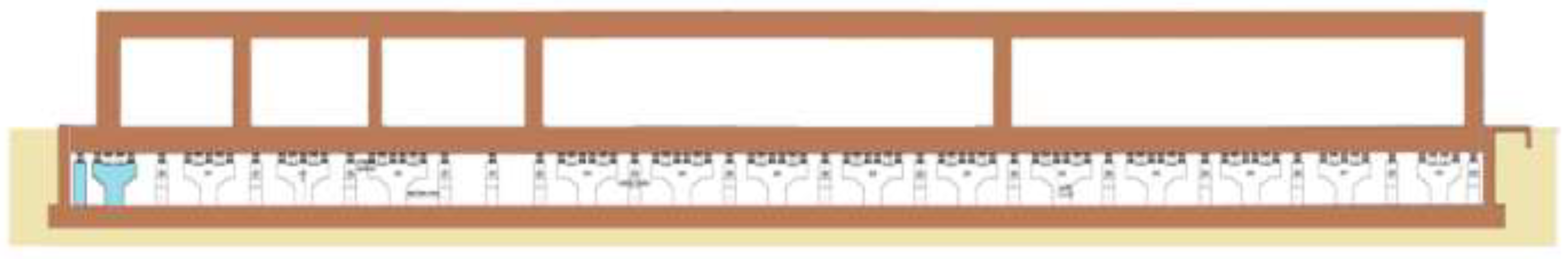
The concrete slab consists of two massive slabs, one 1.5 m thick and the other 0.6 m thick. The overall dimensions are shown in
Figure 1.
The anti-vibration plate rests directly on the columns (
Figure 2), by means of elastic and viscous shock absorbers fixed to the upper end of the reinforced concrete pillars. The anti-vibration plate provides the supporting layer of the floor in the Laser building and the Gamma building.
In the Gamma building, the anti-vibration plate has a thickness of 150 cm, the upper face of the plate is placed at an elevation of 0.10 m, and on the surface of the laser building the anti-vibration plate has a thickness of 60 cm, with the upper face of the plate being located at an elevation of 0.60 m.
The anti-vibration plate is reinforced at the bottom and top with a network of profiled concrete steel bars type B500 (strength class 5, respectively flow limit of at least 500 N/mm2), ductility category C (elongation at breaking—minimum 16%, elongation at maximum force—minimum 7.5%, the ratio between tensile strength and yield strength Rm/Re (Rp = 0.2)).
The pillars are placed on the foundation (
Figure 3). At the top, each pillar has two branches, arranged symmetrically to the vertical longitudinal axis. The anti-vibration plate is completely insulated, and on the entire perimeter of the vertical walls related to the infrastructure of the two buildings, between the edges of the plate and the walls, on the entire perimeter of the plate, an open, continuous joint of at least 100 mm is provided.
The concrete of the slab is of class C35/45, made with CEM III/A cement 42.5 N-LH (cement with reduced hydration heat with resistance class 42.5 N/mm2), and with a water/cement ratio of 0.2. The maximum diameter of the aggregates is 32 mm. The floor is constructed on the upper part of the slab, consisting of a layer of cement-based screed reinforced with polypropylene fibers type CT-C35, with a compressive strength of at least 35 N/mm2. The floor thickness is 10 cm.
The resistance structure is made of steel outer metal pillars and steel metal arches. The steel mark is S355J2G3. The metal structure is protected from fire by intumescent paints. The exterior metal pillars of the Gamma building are equipped with consoles for the running of the overhead crane with a load of 40 tf.
The reinforced concrete pillars, on which the anti-vibration plate rests, have a rectangular cross section, of 3 m high and are provided with brackets at the top on either side of the longitudinal (vertical) axis on which the elastic and viscous shock absorbers are fixed. The foundation of the pillars on which the shock absorbers of the anti-vibration plate rests is placed, is of the 130 cm thick reinforced concrete screed type. The screed rests on the bars with the dimensions of 2.70 m × 1.00 m. In the central area of the platform, the length of the scrap is 28.50 m, for the rest of the platform the support is made on scales of 25.00 m. The Gamma building consists of 15 trusses of 8.0 m and two openings (an opening of 14.45 m and an opening of 39.00 m). The dimensions of the Gamma building are 124.60 m × 42.10 m. There is a space of dilation between the section of the Gamma building and the section of the Laser building.
The elastic support system consists of Maurer Schone-type shock absorbers attached to the ends of the reinforced concrete columns. The elastic shock absorbers consist of two steel plates (the upper plate and the lower plate), between which the helical steel springs are fixed. The system is equipped with screws, which by tightening or unscrewing activate (contact of the anti-vibration plate with the upper plate of the elastic shock absorber) or deactivate the springs (removal of the upper plate from the lower surface of the anti-vibration plate). The height of the elastic supports (spring elements) is 540 mm. The anti-vibration plate is placed on discrete elastic supports and devices with viscous damping. The viscous dissipative system consists of cylindrical metal containers filled with a high viscosity material. Gerb Schwingungsisolierungen viscous shock absorbers are fixed to the brackets of the reinforced concrete columns. The height of the viscous shock absorbers is 660 mm.
The anti-vibration floor is the support on which the equipment and compartments are fixed, including those with the role of radiation protection, resistance function, stability, and static and dynamic deformability determined by the structural elemental position and/or equipment. It is designed in the form of a thick slab, with high rigidity (thickness 150 cm for Gamma building, respectively 60 cm for Laser building) on multiple supports. The rigidity of the upper platform ensures the limiting of deformations due to permanent and dynamic static loads caused by operation, so that the limit state corresponding to its normal operation is not affected. The floor has the function of ensuring the conditions of installation/assembly of equipment.
From the evaluation of the design project of the anti-vibration plate (upper platform) afferent to the Gamma building, it appears that the requirement of mechanical resistance is ensured. The thickness of the plate, the high number of support points and the free distance between the pillar of no more than 3.00 m (usually 2.80 m) satisfy the requirement of stability and the associated deformability normal operating limit state. Additionally, the layer of cement screed reinforced with polypropylene fibers has a strength class and the rigidity corresponding to the support of the equipment and to its mobility.
The cement-based screed floor reinforced with polypropylene fibers has resistance and rigidity to the compression stress corresponding to permanent loads due to the equipment and loads corresponding to normal operation, without deformations that affect the thickness and, implicitly, the flatness of the upper surface.
3. Rigid-Body Model of the Inertial Platform
The radiation protection walls located on the Gamma radiator are 1000 mm, 1500 mm and 2000 mm thick.
Figure 4 shows the radiation protection wall system. A height of 6500 mm was considered (including the thickness of the radiation protection ceiling that rests on the walls).
Geometric modeling of the Gamma + Laser platform with radiation protection walls and radiation protection ceilings (plus roofs) was performed based on the 3D model (
Figure 5). The ceilings are made of prefabricated reinforced concrete, mounted without gaps on the radiation protection wall system. The ceilings, located at a height of 5000 mm, are represented in yellow and the ceilings of the rooms with a height of 6500 mm are represented in red (
Figure 6a).
The construction structures on the Gamma platform include radiation protection walls, radiation protection ceilings, as well as overhead ceilings with the role of thermal protection of ceilings and floors. As the roofs are made of materials of very different densities and the reinforced concrete prefabricated roofs are positioned at a distance from each other, for reasons of mass distribution, an equivalent thickness of 750 mm over the entire roof surface was considered.
Figure 6b shows the simplified 3D model of the Gamma + Laser monolithic platform with radiation protection roofs as well as the ceilings.
Inertial description of the platform
In order to determine the inertial characteristics (total mass, position of the center of mass C, central axial moments of inertia and central centrifugal moments of inertia), geometric models constructed in the following hypothesis were used: the platform is homogeneous, made of reinforced concrete with a density:
ρ = 2600 kg/m
3. The total mass as well as the second order moments of inertia were determined both by analytical methods and using CAD modeling in Autodesk Inventor
® 2019, with both sets of results being identical (first 6 significant digits).
Table 1 shows the central inertial characteristics of the Gamma + Laser monolithic platform with radiation protection walls and ceilings and reinforced concrete roofs.
A model of the elastic support system with steel helical springs (Maurer) was made based on the geometric model of the Gamma + Laser platform (
Figure 6), the position of the center of mass C and the position of the supports elements of the platform.
For the modeling of the elastic support system with steel helical springs, the linear elastic characteristics in
Table 2 were taken into account.
For modeling the viscous damping system with Gerb devices, the linear damping coefficients in
Table 3 were taken into account in accordance with the technical documentation.
The general expression for the inertia matrix for the platform considered as a rigid body, with central reference frame Cxyz, is as follows:
where
m is the total mass of the platform and
Jx, Jy, Jz, Jxy, Jyz and
Jzx are the moments of inertia of the solid-rigid platform. The inertia matrix can be written as:
where:
Table 1 shows the inertia characteristics of the Gamma + Laser platform with walls, floors and roofs and arranged in a matrix below. The coordinates used in the dynamic analysis of the platform modeled as a rigid body with 6 degrees of freedom (
Figure 7) are:
x—lateral translation of the center of mass C;
y—longitudinal translation of the center of mass C;
z—vertical translation of the center of mass C;
φx—rotation of the platform around the central axis Cx;
φy—rotation of the platform around the central axis Cy;
φz—rotation of the platform around the central axis Cz.
After performing the relevant calculations and taking into account the dimension of the slabs and the density of concrete, the inertia matrix becomes:
The measurement unities for are kg, for and are kgm and for are kg m2.
The general form of the stifness matrix is:
For the elastic supports (links) of the rigid body, the following are defined:
►—the total number of elastic support;
► —the coordinates of the elastic support;
► —three-orthogonal elastic coefficients of the support.
Depending on the total number of supports,
n, the triorthogonal elastic characteristics of the supports
and the positioning characteristics
of these supports/links, the stifness matrix can be written in the form of submatrices as follows:
where:
The elastic matrix of the Gamma + Laser platform (with walls, ceilings and roofs) and all the activated elastic support devices was determined based on the positioning plan of the 468 supports of the platform (Gamma—355 supports, Laser—109 supports, Monolithic area—4 supports) and the coordinates of the elastic support elements and the coefficients of elasticity. The
matrix is the stifness matrix of the Gamma + Laser platform with walls, floors and roofs.
The measurement unities for are N/m, for and are N and for are Nm.
The general form of the viscous damping matrix for a rigid solid with viscous damping supports related to the Cxyz central reference frame is:
where
are the viscous damping coefficients corresponding to the six generalized coordinates of the dynamic study. Viscous liaisons are defined as:
►—the total number of viscous liaisons;
► —the coordinates of the viscous liaisons;
► —damping coefficients.
Depending on the total number of supports,
m, the three-orthogonal elastic characteristics of the supports
and the positioning characteristics
of these supports/links, the damping matrix can be written as follows:
where:
Below, the damping matrix of the Gamma + Laser platform with walls, floors and roofs is presented:
The measurement unities for are Ns/m, for and are Ns and for are Nsm.
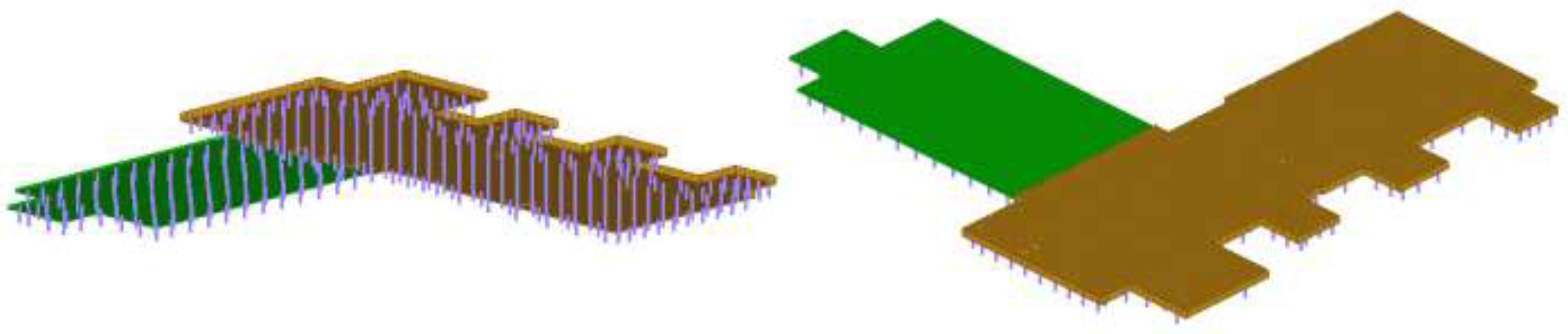
A finite element model (
Figure 8 ) is made by considering the geometric and mass characteristics of the concrete slab [
19,
20,
21], as presented in
Section 2 [
22,
23,
24,
25,
26,
27,
28,
29,
30,
31].
The model aims to study the vibrations of the concrete platform placed on batteries of linear elastic springs, at approximately equal distance. In this case, due to the FEM model¸ the vibration equations of the system can be written as [
32]:
Here, represents the inertial matrix, the damping matrix and the stiffness matrix (these three matrix are real, symmetric and positive definite). The vector contains the generalized displacements, the generalized velocities and represents the generalized accelerations.
The motion equations of the free vibration of this system are:
The harmonic time dependence equation is:
where
C is an arbitrary constant,
is the circular frequency, and
is the initial phase shift and
is the vector of amplitudes.
Combining Equations (18) and (19) leads to:
Equation (20) has a nontrivial solutions if and only if:
Using Equation (21), the polynomial can be obtained as follows:
If matrices
and
are symmetric and positively defined, Equation (22) has
n real and positive numbers:
in general distinct, roots (referred to as eigenvalues). The linear homogeneous system (4) can be written in the form:
For every , it obtains the solution , . These vectors represents the eigenmodes of vibration.
4. Results
The following results were obtained in a study of the eigenfrequencies of the platform, which is considered to be a rigid structure suspended on elastic supports, with six degrees of freedom. The natural frequencies of the platform are listed in
Table 4.
The eigenvectors corresponding to the six eigenpulsations are presented synthetically in
Table 5 (normalized after the translational motion
x).
In the case of the model with finite elements of the concrete slab that is considered elastic, the eigenfrequencies of the system are obtained (see
Table 6). In the same table, we have introduced, for comparison, the eigenfrequencies for the system considered as a rigid body with six degrees of freedom and the eigenmodes of vibration. It can be observed that the first three eigenfrequencies for the rigid body platform supported on the springs are very closed to the eigenfrequencies of the elastic platform supported on the elastic springs. For the higher eigenfrequencies, the modes of vibration due to the elasticity of concrete, overlap the rigid mode of vibration. From the 4th to the 14th eigenmodes, there are elastic eigenmodes. Only the 15th mode of vibration can be identified as a rigid mode of vibration but with components that derive from the elasticity of the platform itself.
5. Discussion
The study of the vibrations of the platform placed on elastic springs was modeled as a rigid body with six degrees of freedom. This description does not take into account the elasticity of the concrete with which the platform is made. The number of degrees of freedom is therefore six and following the calculation, six eigenfrequencies are obtained, which describe the rigid motion of the platform. In order to verify this model, which is a simplified model, the FEM model is used, in which the elasticity of the concrete of the platform is also taken into account. In this case, in addition to the eigenfrequencies obtained by considering the platform as a rigid body, there are a number of modes of vibrations that take into account the elastic deformation of the concrete. These vibration modes are calculated and the motion modes are represented. It is found that the first three modes of vibration of the platform are also the first three modes of vibration of the platform that is considered elastic. The fourth vibration mode of the motion of the modeled platform, as a rigid body, can be identified with the 15th mode of movement of the FEM model. The other two vibration modes of the rigid body are more difficult to identify, as rigid mills overlap over the elastic behavior of the platform. We can therefore conclude that the first three modes of vibration obtained by the simplified calculation overlap with the first three modes of the elaborated model, calculated with MEFAs a result, the lowest modes of vibration of the platform can be obtained quite quickly, with a simplified calculation, i.e., the lowest modes of vibration, which matter in such an analysis. To determine the most important parameters of a structure in a short period of time is important in a design process.
6. Conclusions
The approach of research, technical investigations and evaluations was based on the modal analysis of the support plate in order to identify the critical frequencies of resonance to external excitations from earthquakes and/or dynamic sources in the environment.
Based on the dynamic response of the support plate in the two variants in the overall structural configuration as well as in the situation of removing a wall from the Gamma tunnel board, the following conclusions can be drawn:
- (a)
The modal analysis highlights the fact that the support plate that is modeled as a rigid body with six degrees of freedom can be excited from the outside on six eigenfrequencies, and each eigenmode of vibration can constitute a vulnerability factor in case of an earthquake with magnitude over 5 degrees Richter;
- (b)
The dynamic response of the support plate represents an overlap of its rigid eigenmodes of vibration with those of the deformable plate as a result of the bending. For this reason, the whole spectrum of response to seismic excitations must be analyzed.
Based on the constructive technical data, the mechanical characteristics and the adjustment/maintenance conditions for the Laser-Gamma support plate, the following development steps are proposed as future development directions:
- (a)
Establishing the horizontality requirements for the static balance of the support plate and the method of adjusting the springs by selective activation;
- (b)
Establishing the level of allowed vibrations transmitted from the environment from natural sources (microseisms, earthquakes) or anthropogenic sources;
- (c)
An analysis of the dynamic response of the support plate with the complete Laser-Gamma equipment for the categories of earthquakes based on seismic zoning according to the names;
- (d)
Technical approval of the viscous damping system from the set of viscoelastic supports for which there is no evaluation;
- (e)
Establishing technical solutions for equipping the support plate to reduce seismic shock and limit travel in the event of an earthquake with a magnitude of greater than 7 on the Richter scale.
It is necessary to analyze the existing situation in order to ensure, in case of an earthquake, the support plate equipped with Laser + Gamma.
We can conclude, finally, that it is more convenient to calculate the vibration of the platform supported on elastic springs that is considered as a suspended rigid platform, with six degrees of freedom, than to perform calculations based on a model with finite elements, which also considers the elasticity of concrete. It has been found that the first three eigenfrequencies of the complex model are very close to the first three eigenfrequencies of the system considered as a rigid. However, the calculation effort made for the analysis of the two models differs a lot. A calculation of the rigid body model supported on springs, with six degrees of freedom, can be performed quickly and requires a much smaller computational effort than required for the calculations in the finite element model. In this way, important information on the behavior of the platform can be obtained within a short timeframe.


 ,
, 


