
A Review on Hot Stamping of Advanced High-Strength Steels: Technological-Metallurgical Aspects and Numerical Simulation


1
Faculty of Mechanical Engineering and Computer Science, University of Bielsko-Biala, Willowa 2 Street, 43-309 Bielsko-Biala, Poland
2
Department of Engineering Materials and Biomaterials, Faculty of Mechanical Engineering, Silesian University of Technology, 18A Konarskiego Street, 44-100 Gliwice, Poland
*
Author to whom correspondence should be addressed.
Symmetry 2022, 14(5), 969; https://0-doi-org.brum.beds.ac.uk/10.3390/sym14050969
Submission received: 14 April 2022
/
Revised: 29 April 2022
/
Accepted: 6 May 2022
/
Published: 9 May 2022
(This article belongs to the Special Issue Symmetry/Asymmetry in Hot Forming and Numerical Simulation)
Abstract
:The production of ultra-high strength automotive components requires a multi-directional approach. Hot stamping combines both forming and heat treatment processes to obtain a usually martensitic structure of complicated shaped automotive parts. The preparation for production using hot stamping must involve the latest methods of numerical analysis of both temperature changes and forming, which are applied for an increasing range of materials used. In this paper, the current state of knowledge about the basics of hot stamping, used technological lines, and the current state of material used with applied heat treatments and possible coatings have been reviewed. Moreover, the numerical modeling process has been described. The most important aspects of process automation, including the use of digital twins for simulation and optimization of operational kinetics of the robots accomplishing the production process, analysis and minimization of time of production cycles, and searching for weak operational points of the control systems and for real time visualization of operation of complete line, are considered. The digital twins and corresponding numerical models enable the symmetrical design of real production lines. The details of heat treatment profiles with so called tailored zone heat treatment are provided. Hot stamping is a dynamically developing technology as evidenced by the increasing range of materials used, also from the 3rd generation of advanced high strength (AHSS) steels. It starts to combine forming of symmetric or asymmetric elements with more complex heat treatment processes as required for dual phase (DP) stainless steels or the newest generation of high-strength and ductile medium-manganese steels.
1. Introduction
The reduction of fuel consumption, decreasing emission limits of greenhouse gases, and permanent improvement in safety of drivers and passengers constitute one of the main objectives for producers of modern cars and other transportation vehicles [1]. The answer to these postulates can be the reduction of the mass of developed structures of vehicles [2,3]. A certain regularity can be observed, whereby new models of popular cars are lighter comparing to the previous models by 20% at least [4]. This trend has increased even more in the case of electric car designs, where the mass of a battery needs to be compensated for. The reduced mass of the car body structures is possible owing to new ultra-strength materials used for the construction of these structures and implementation of new manufacturing technologies. The hot stamping process belongs to one of the most effective and industrially accepted technologies. In 1984, Saab Automotive for the first time used hot stamping technology to produce components of car body structures [2]. The door beam was manufactured in mass production technology. Currently, using such technology, 15–38% of weight of all drawpieces being part of car body structures are produced, and one estimates that in the successive years the percentage of hot stamped symmetric or asymmetric drawpieces in car body structures will be growing [5].
As hot stamping technology is constantly developing and optimizing, it is necessary to update the current opinion on this subject. Modern advanced steels are introduced into the production process [2,6,7,8], allowing for the extension of the available range of strength and plastic properties [9]. Thus, it increases the application possibilities of this technology [10]. The design process is continuously refined using the latest simulation methods [3,11,12,13]. However, there are still many challenges and problems that require further work on this topic. Given the rapid development of hot stamping, it is necessary to summarize the current state of knowledge on this topic, which is the purpose of this work.
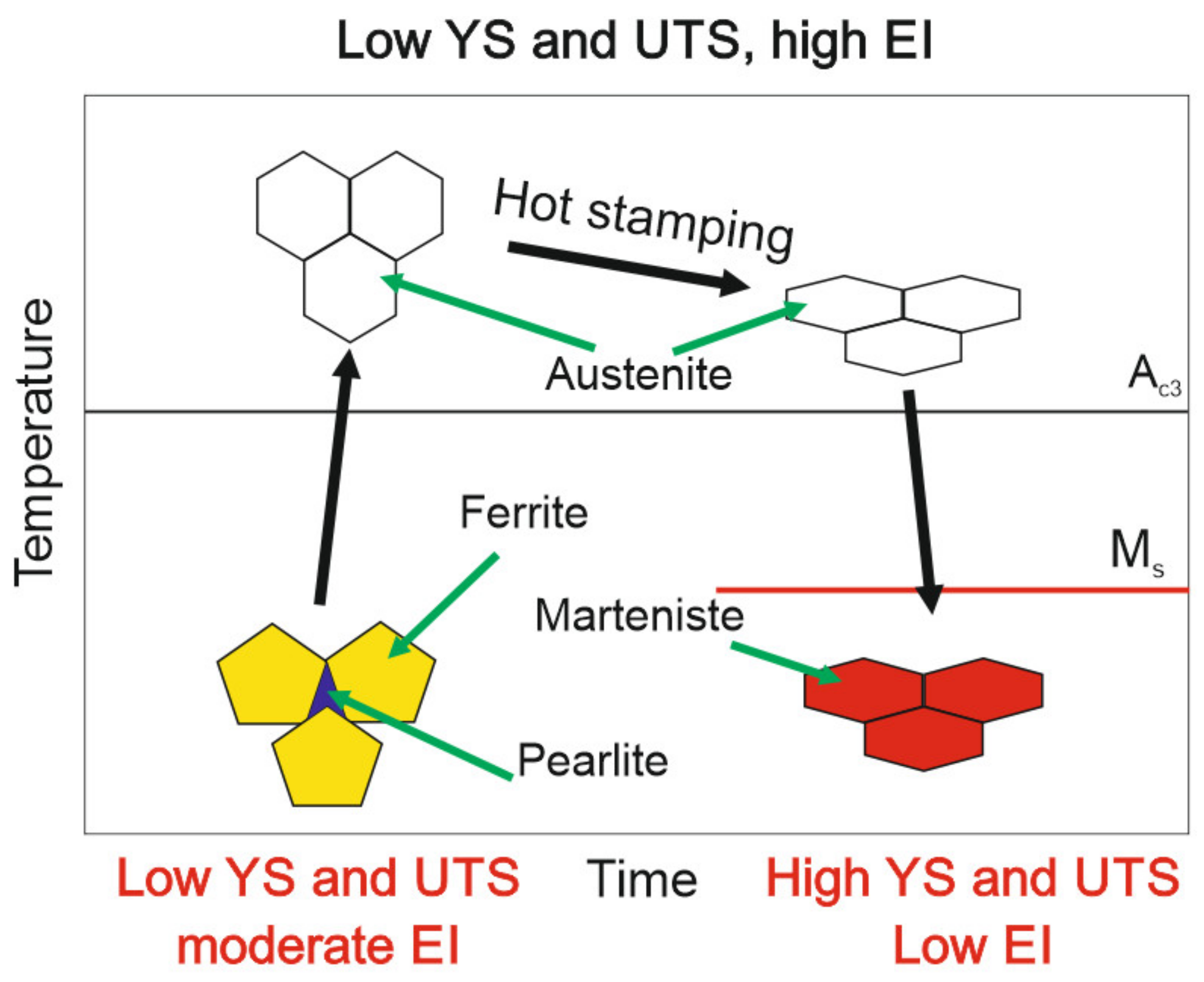
The hot stamping process is a combination of two operations (Figure 1): operations of forming and heat treatment (usually quenching) [14,15]. After heating-up ferritic-pearlitic sheet steel to austenitization temperature, it is possible to obtain a required shape of the drawpiece, while quick cooling-down in the press, causing martensitic transformation, results in a considerable increase in the strength of the steel and the production of finally shaped elements having very high strength and a martensitic structure. Such a geometry–strength relationship is currently impossible to obtain in another way [16].
2. Technological Line and Process Automatization
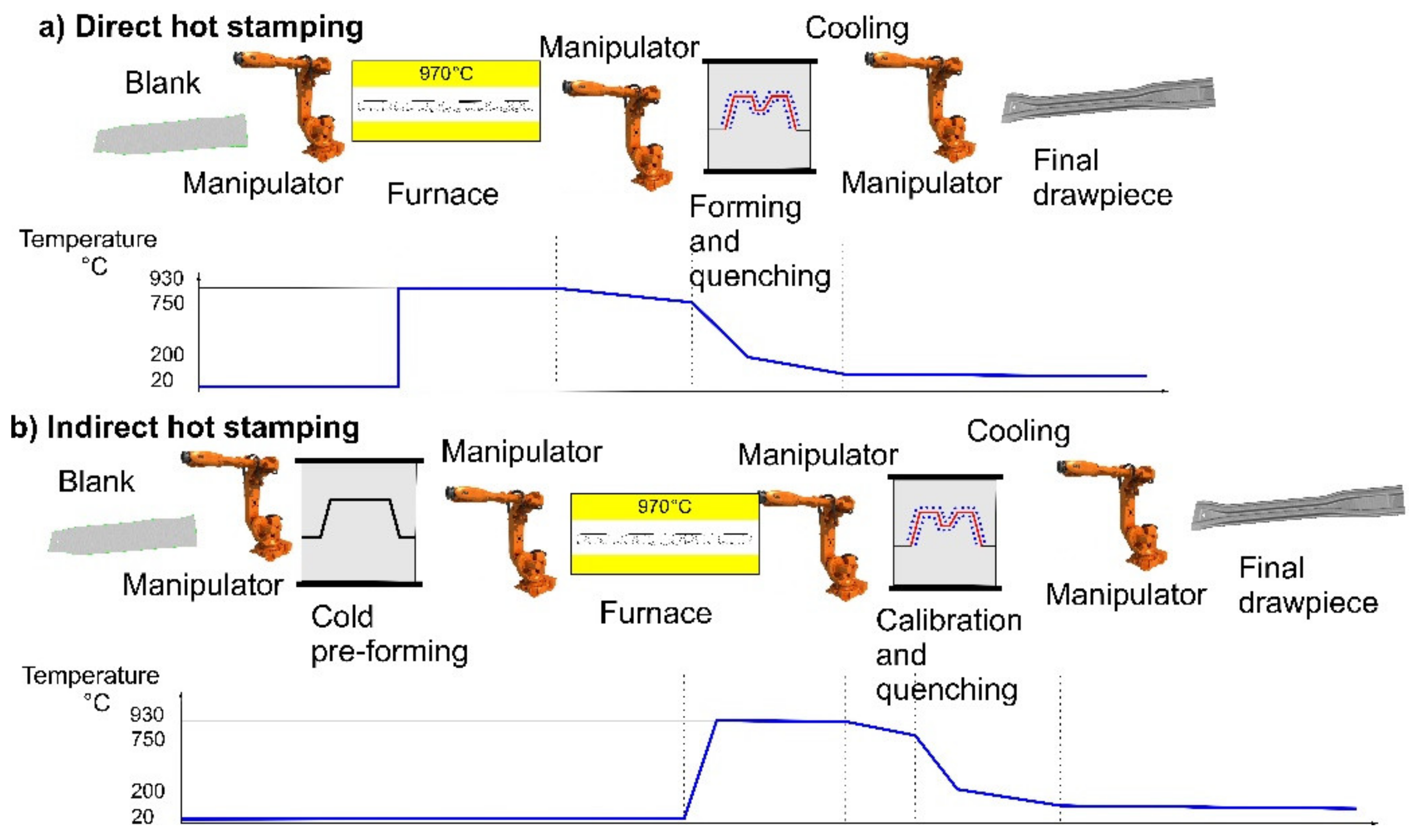
The hot stamping process can be divided into two methods: direct and indirect ones. In the direct method, a flat blank, after being heated in a furnace, is transported to a press, where forming and quenching of the drawpiece within closed and water-cooled tool (stamping die) occur. In case of the indirect method, an initially shaped drawpiece (cold pressed) is heated-up in a furnace, and next transported to cooled tool (stamping die) in a press, where final shape calibration of the drawpiece and its quenching occur. In Figure 2a, a scheme of the direct process is presented, while in Figure 2b the indirect process, together with values of temperature of processed blank and drawpiece at each step of their production, are illustrated.
In result of the hot stamping process, the drawpiece material can reach tensile strength values within a range 1500–2000 MPa. This technology also allows production of drawpieces with diversified mechanical parameters, and hence, with diversified stiffness [17,18]. There is a possibility to distinguish several methods of their production. The most important are:
- -
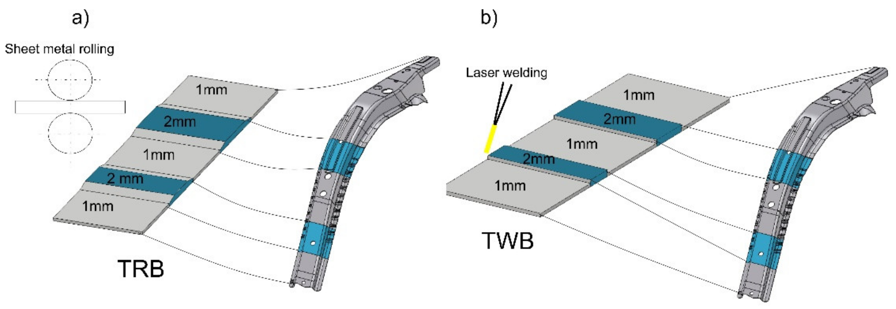
- Usage of specially rolled steel sheets of various thickness (Figure 3a). In areas where the stiffness of the drawpiece should be lower, the thickness of the steel sheet is lower, whereas in areas where the stiffness should be higher, the thickness of the steel sheet is higher. This is so called Tailor Rolled Blanks (TRB). The thickness of the steel sheet varies continuously in course of rolling. Flat blank cut-off from steel sheet of various thickness is formed and quenched in the process of hot stamping.
- -
- Usage of steel sheets having different thickness to the production of the flat blanks joined together with use of laser welding (Figure 3b). Laser welding can be performed during production of the material, or directly by a manufacturer of the drawpieces. The flat blank produced in such a way is formed and quenched in process of the hot stamping. It is so called tailor welded blanks (TWB).
- -
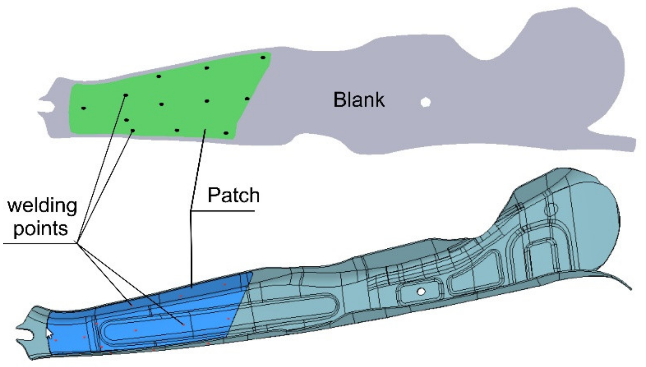
- Usage of a flat patch resistance, welded to the flat blank, which in the next step is hot stamped (Figure 4). In area, where the patch is used, the drawpiece features a higher stiffness comparing to other areas. These are so called patchwork blanks.
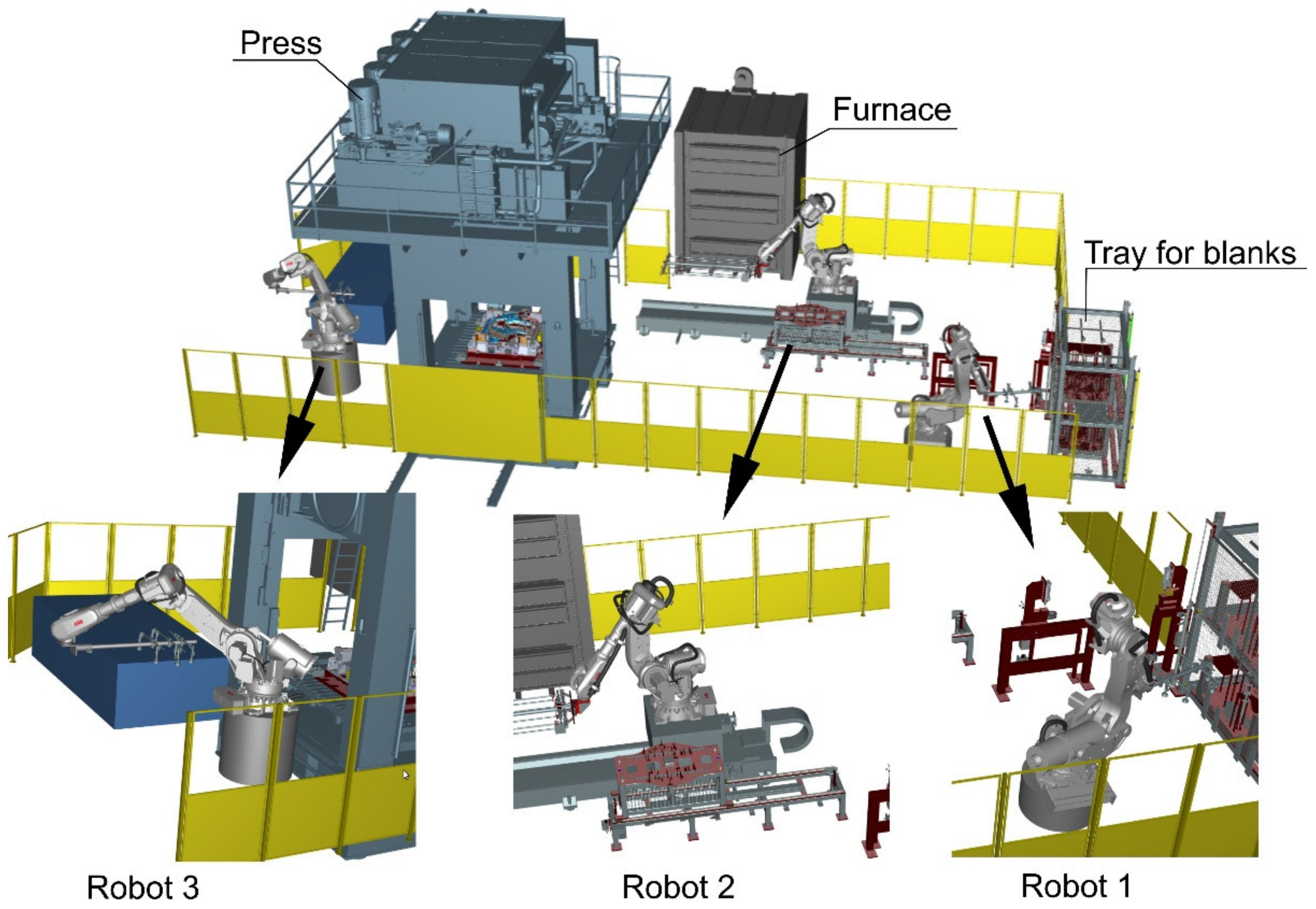
The hot stamping technology is a fully automated process. At the beginning, the flat blank is taken from a tray and is marked (robot 1). In the next step, the blank is transferred to a furnace, and after heating-up the blank is transported to the stamping die in the press (robot 2). The process is completed by taking the ready drawpiece from the stamping die and moving it to conveyer (robot 3), the same as shown in Figure 5. During the development of automated lines to the hot stamping process, in the first succession, a so-called digital twin of the line is developed. This constitutes a faithful representation of the automated manufacturing line in the form of a complex computer model [1].
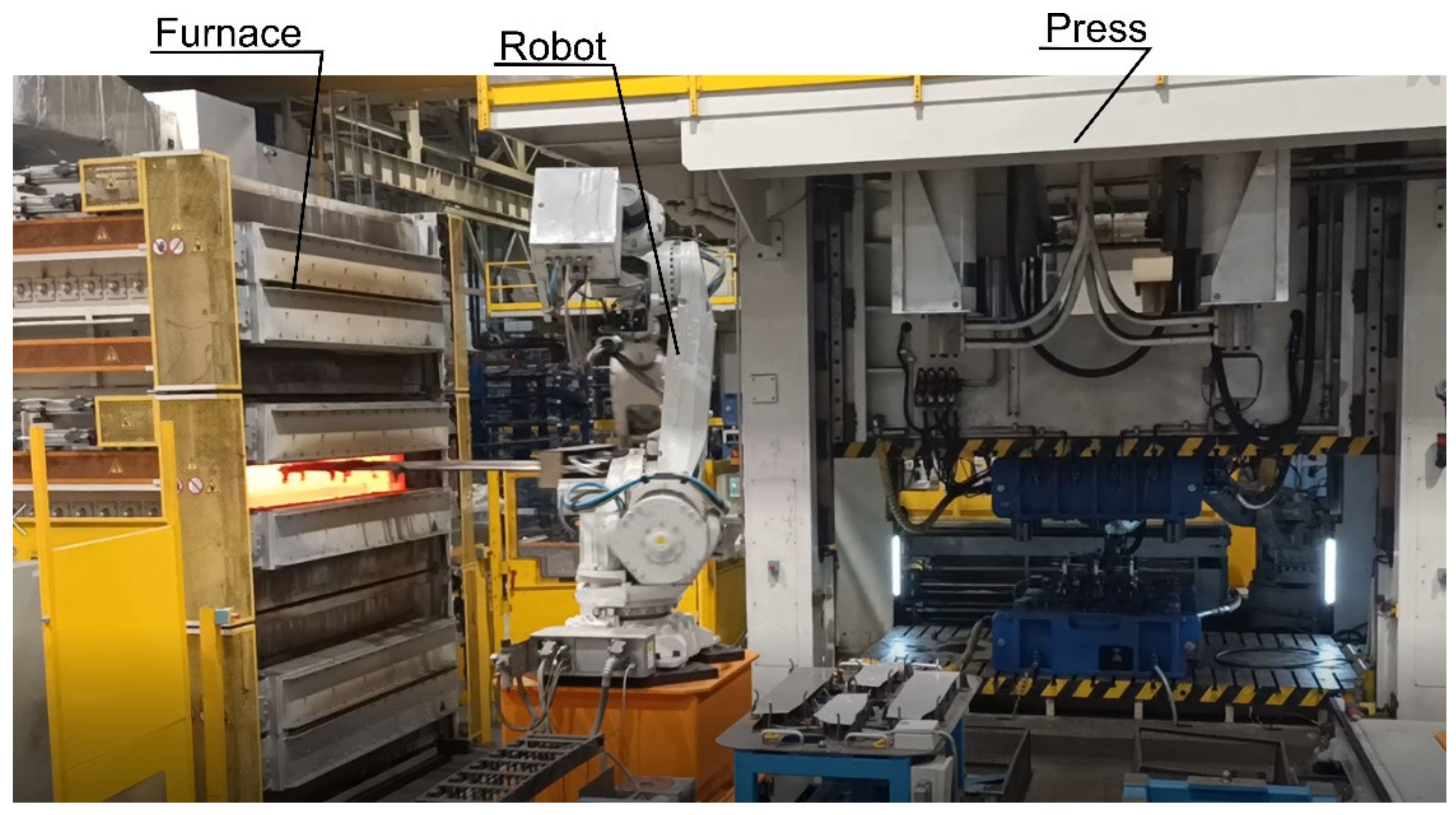
A digital twin of the hot stamping line (Figure 5) consists of: 3D CAD models of the most important components of the line like industrial robots, furnace, press, tool, running tracks, holding tables, conveyers, and auxiliary tooling. Models of PLC controllers are constructed as well, and control programs for driver elements of the complete line are written. Tecnomatix software produced by Siemens represents a digital environment for the elaboration of the digital twins of the automated hot stamping production lines [19]. The digital twin allows for the simulation and optimization of operational kinetics of the robots accomplishing production process, for analysis and minimization of time of production cycles, searching after weak operational points of the control systems, and for real time visualization of operation of the complete line. Based on the digital twin, the symmetric real production lines can be constructed. In Figure 6, a fragment of the real hot stamping line is shown, which is responsible for loading of the cold blank to a furnace and transporting heated blanks from the furnace to a stamping die in the press.
The elaborated digital twin is used many times for the development and optimization of each newly prepared manufacturing process (new type of drawpiece), having in mind all aspects connected with its automation. This considerably shortens the time of setting into the production of new products.
3. Conventional High-Strength Steels
Implementing technology of the hot stamping and special steel grades allowed to produce car body drawpieces with very high mechanical properties and considerably reduced mass, compared with drawpieces produced from traditional steels and in cold stamping processes. Such technology allows also for the production of car body elements with tailored (as proposed by design engineer of car body structure) mechanical parameters. The hot stamping allows for significant elimination of the biggest disadvantage of cold stamping technology for advanced high-strength steels (DP, transformation induced plasticity (TRIP)), as the springback is.
Steels for hot stamping have to exhibit (1) high YS and UTS after hot stamping; (2) the hardenability has to allow for complete martensitic transformation in used die; (3) delayed ferritic and pearlitic transformations to prevent the diffusional transformations during blank transfer to a press; (4) adequate weldability for given application. Such a combination of properties depends substantially on a chemical composition. The most essential elements in such steels are:
- Manganese, which is added to almost all steels as it is used as a deoxidizer. It also reduces the susceptibility to hot brittleness during hot working [22]. Mn like carbon increases the hardness. However, usually it is connected to the reduction in ductility and weldability. For the hot stamping technology a decrease in austenitization temperature caused by manganese addition is important as it allows to save some energy and reduce the carbon emission [6].
- Boron, which significantly increases the hardenability of steel by promoting the formation of carbides. As shown by Naderi et al. [23], boron addition is necessary to obtain a fully martensitic microstructure in typical hot stamping process.
Steels used in the hot stamping technology are also sometimes alloyed with other elements, whose influence on phase transformations [1] is shown in Table 1.
3.1. 22Mnb5 Steel
The grade usually used for hot stamping is a manganese-boron 22MnB5 steel (material number 1.5528) [2]. It is an economic low carbon steel, alloyed with manganese and boron, which in soft conditions exhibits a ferritic-pearlitic microstructure with a grain size of >10 μm. The typical chemical composition and mechanical properties are given in Table 2. The in-situ quenching following hot forming results in the possibility to obtain parts with YS of over 1000 MPa and UTS of ~1500 MPa [24].
3.2. Steels with Improved Strength
As mentioned earlier, the simplest way to improve the YS and UTS under given heat treatment conditions is to increase a carbon content [26]. Table 3 shows changes in mechanical properties with increasing carbon content in a group of Mn-B alloyed steels. Unfortunately, the increased strength results in decreased toughness/energy absorption, elongation, cracking, and worse weldability.
3.3. Materials with Improved Strength and Ductility
Hot-stamped parts exhibit very high strength. However, their elongation is strongly limited [27]. This relation limits its use only in parts, where intrusion resistance is necessary. Nowadays, materials maintaining both high strength and increased plasticity are more often required. Such materials may replace lower-strength steels, which simultaneous potential of weight decrease of a given part. Research on new steel grades is performed in two major directions [1]:
- UTS level 450–600 MPa (for energy absorption areas) with increased elongation (>15%): steels containing ~0.1%C, 1.1–2.0% Mn, ≤0.005% B, and ≤0.5 %Si
- UTS level 1000–1300 MPa (for intrusion resistance areas) with maintained elongation (>5%), steels containing: 0.12–0.2%C, 1.0–2.0% Mn, ≤0.005% B, and ≤0.5 %Si
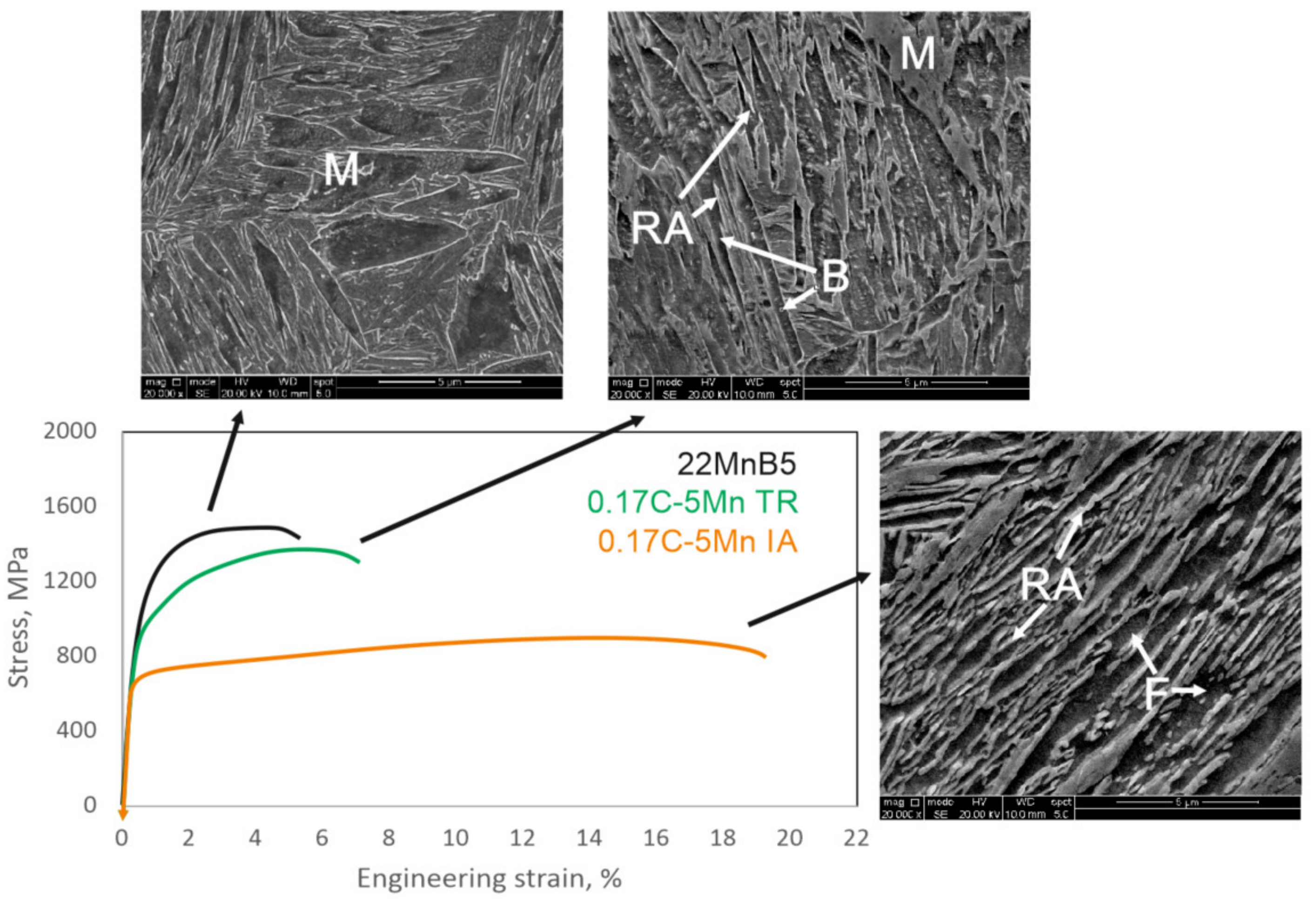
The tensile behavior and exemplary microstructures of typical martensitic 22MnB5 steel and two types of advanced steels are presented in Figure 7. The thermomechanically rolled 0.17C-5Mn TR steel with bainitic-martensitic microstructure and retained austenite (RA) shows strength properties similar to the 22MnB5 steel with better ductility. Such steel is suitable for intrusion resistance areas. The same steel but subjected to intercritical annealing treatment at 685 °C for 5 min shows a mixture of fine laths of ferrite and retained austenite. Such a microstructure provides much better ductility and energy absorption characteristics at lower strength properties. Therefore, such steels are designed for energy absorption areas.
4. Heat Treatment Profiles and Tailored Heat Treatment
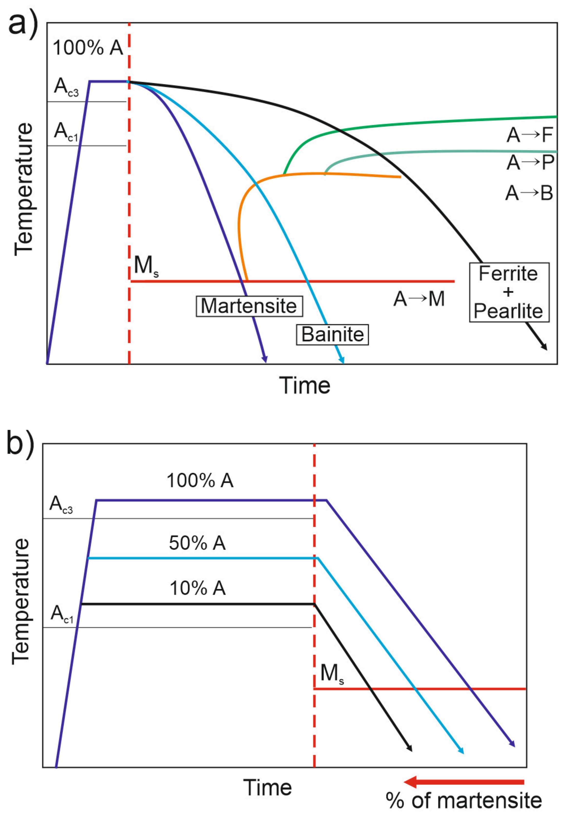
Properly selected technological parameters of the hot stamping process, such as soaking temperature in furnace, time of transportation of the blank from the furnace to press, cooling rate in the press, and quenching time, are responsible for required final effect of the stamping [28,29]. All the above mentioned factors are critical for the final mechanical and metrological parameters of drawpieces [30]. In process of the hot stamping, the steel sheet (flat blank) is transformed from ferritic-pearlitic structure into a drawpiece having martensitic structure. Moreover, a high cooling rate amounting to 27 K/s at least is required [2]. Reduction of the cooling rate leads to the generation of some percentage of bainite in microstructure (Figure 8a), or even pearlitic-ferritic structure. Therefore, due to control of the cooling rate, it is possible to achieve a wide range effect on mechanical properties of ready drawpiece. Moreover, the temperature to which the blank is heated-up can be selected to modify the microstructure prior to the forming (Figure 8b).
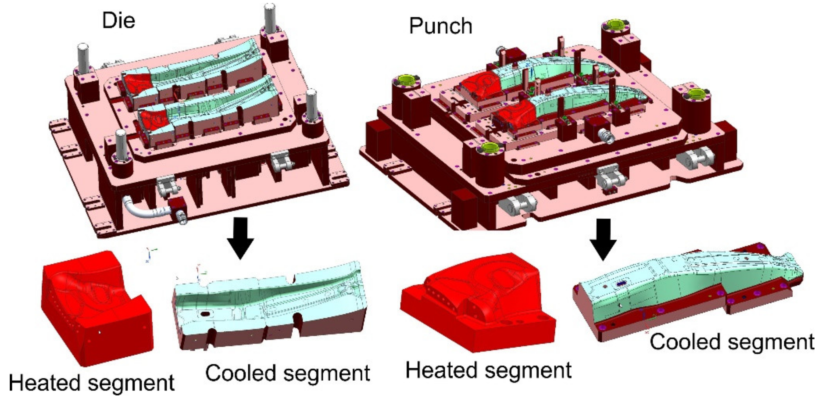
This is implemented nowadays in so called tailored heat treatment [31], which involves the usage of specially developed tool, i.e., stamping die, which incorporates heated segments (with cartridge heaters) in areas where a soft zone should be generated, and cooled segments (with water), where hard zones need to be generated (Figure 9). Martensitic transformation does not occur in the contact area of the formed drawpiece and heated segment of the tool, and lower values of mechanical parameters are obtained.
In the soft zone, the material can feature a microstructure being a mixture of bainite and martensite, bainite, ferrite, and martensite, or ferrite and pearlite [32].
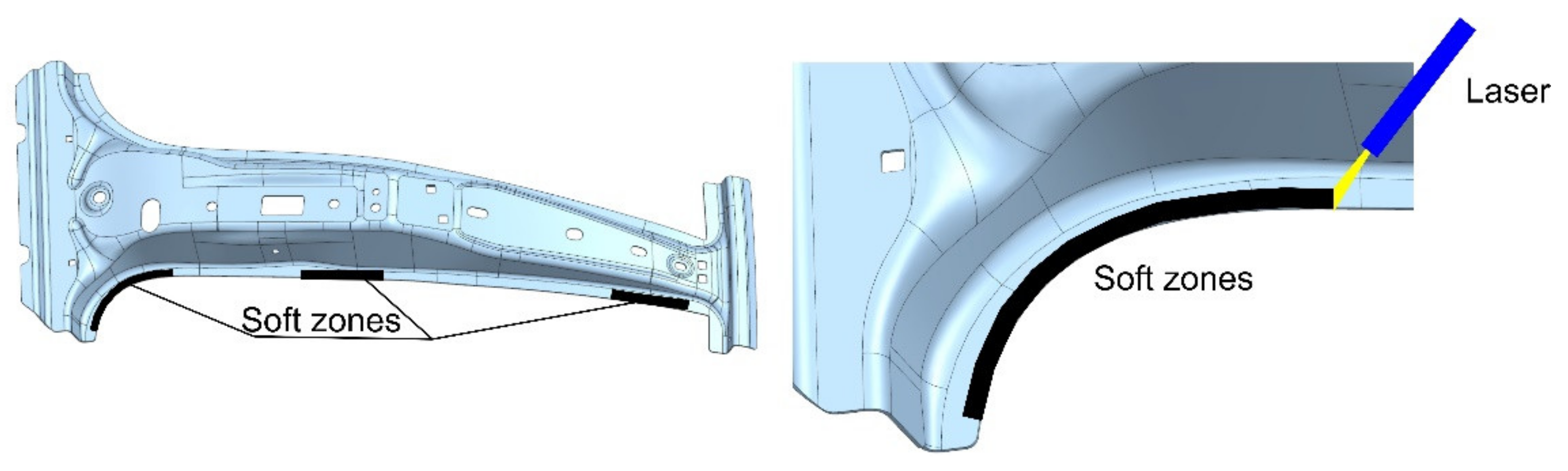
The soft zone can be also generated after process of the hot stamping. This method involves usage of laser beam source (Figure 10) or induction heating [33] to tempering and softening of some areas of the drawpiece. Split and moving laser beams, attached to the wrist of an industrial robot, heat-up narrow zones of the drawpiece, generating soft zones of required shape. This is a good method for obtaining the soft zones with small dimensions and complex shape.
5. Numerical Modelling
Computer simulation of the hot stamping process represents one of the basic tools during the anticipation, analysis, and elimination of problems that could arise during launch of new manufacturing processes. Numerical modelling allows for [3]:
- verification of design concept of the tool and its indispensable components (die, punches, clamps),
- analysis of correctness of operational kinetics of the stamping die (sequence of operations of individual components of the stamping die, their feedrate, travel of the press),
- verification of the feasibility of production of the drawpiece through an analysis of thinning of the drawpiece wall, risk analysis of generation of zones with wrinkles or cracks,
- analysis of the hardness and analysis of the microstructure (percentage fractions of phases), hardening deformations of the drawpiece,
- analysis of the cooling system of the tool (temperature of the tool, elimination of hot spots),
- analysis of forces acting in the press necessary to shape drawpieces.
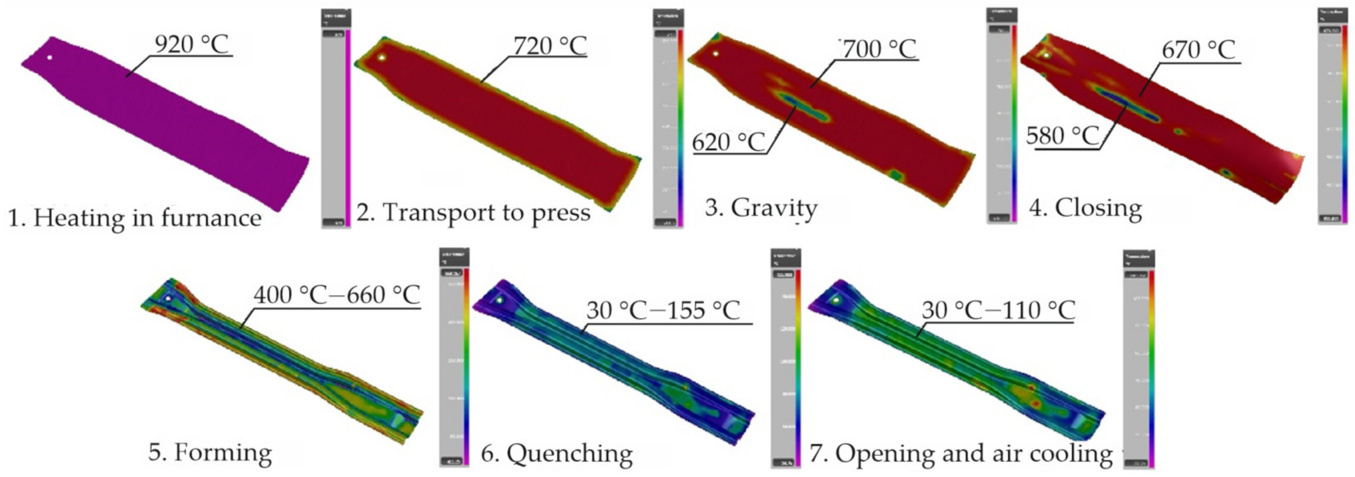
Computer simulations of the hot stamping process belong to coupled simulations from fields of mechanics, metallurgy, and heat exchange. The process of simulation is divided into a few stages (according to real run of the process): heating-up, transport to stamping die, gravitation, holding in the tool, stamping, quenching, opening of the tool together with cooling of the drawpiece in the air. Temperatures of the blank and the drawpiece at all simulation stages of the hot stamping are presented in Figure 11.
Operations 1–3 are analyzed as coupled thermo-mechanical analysis, in which heat exchange between the blank and its surroundings occurs; and with thermal expansion of the blank and deformation of the blank under the effect of gravitation taken into account. Operations 5–7 are included into coupled thermal-mechanical-metallurgical analysis. A change of shape of the blank during stamping, metallurgic transformations, and analysis of hardening deformations take place in the heat exchange between the blank and the tool. To take the above-mentioned phenomena into the FEM simulations of the hot stamping process, a detailed description of the material model of the blank is necessary. The most important parameters of this model can include the following.
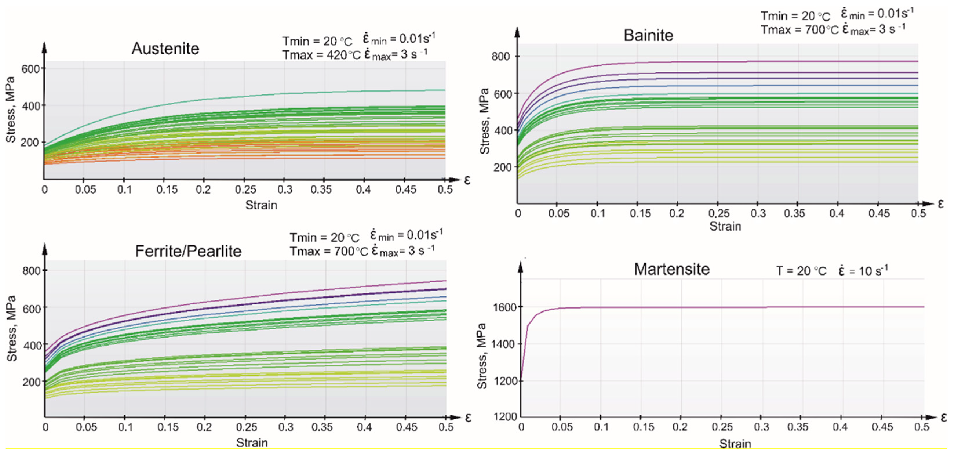
The strengthening curve is a function of temperature and strain rate. In the studies [34,35,36], experimental tests of the 22MnB5 steel at different temperatures and various strain rates are discussed in detail. A correct mathematical model requires generating numerous strengthening curves in a wide range of temperature and strain rate, which cover the whole possible processing window of the hot stamping. The temperature and strain rate dependent mathematical description was made. Figure 12 presents typical strengthening curves as a function of temperature and strain rate for the 22MnB5 steel [11]. The curves in the diagram are determined in the same temperature range (from 20 °C to 850 °C) and metallurgical phases (austenite, ferrite/pearlite, bainite, martensite), in which the hot stamping process is carried out. Each figure represents a wide range of tensile curves for the successive microstructures generated in a representative strain rate range and a temperature range.
Young’s modulus depends on temperature. Most often, it is the linear dependency determined between two points: for t1 = 20 °C, E = 2.1e5 GPa and for t2 = 950 °C, E = 4.5e4 MPa [11].
Curves of phase transformation are evaluated on the base of CCT diagrams [37]. In [19,38,39], the authors elaborated advanced material’s model comprising phase transformation and implemented it into a commercial FEM program [11].
The limit curve of stamping depends on temperature and strain rate. In [40], the authors proposed the description of deformation using the forming limit diagrams (FLD), based on the Lemaitre law [41]. Parameters of the material have been identified in the experimental way [11].
The thermal expansion coefficient considers change in density, caused by phase transformation of the steel and is described by the following dependency [11]:
where:
- is the volume fraction of the phases Austenite, Ferrite/Pearlite, Bainite or Martensite,
- is the linear expansion coefficient of phase k,
- is the initial blank temperature,
- is the transformation strain of phase k.
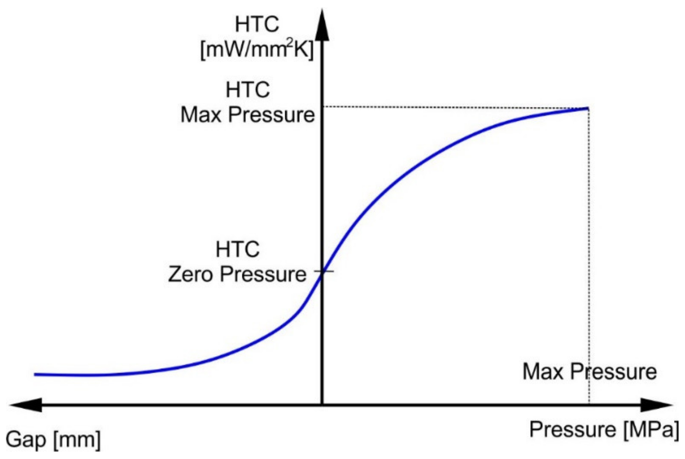
It is also very important to define suitable conditions for heat conduction between the blank and the tool (die, punch, and clamp) and surroundings. As evidenced in [30,42,43,44,45], the heat transfer coefficient (HTC) from the blank to the tool depends on a value of the pressure, which the tool puts against the blank (drawpiece), and on the size of the gap between them. This dependency is presented in Figure 13.
In the simulation of the hot stamping process, temperatures at working surfaces of the die, punch, and clamp are additionally calculated. Discrete models of the dies, punches and clamps incorporate models of cooling channels. In [46], some characteristics of the heat exchange between the tool (die and punch) and water flow in cooling channels have been investigated. The authors’ proprietary tooling was elaborated to measurements of the heat transfer coefficient from the die to the channel. In practical applications, the heat transfer coefficient is responsible for the heat exchange between the die (punch) and the cooling channel. Most often, it takes a default value of HTC = 14.800 mW/(mm2K) [11].
In the case of Autoform commercial software, a discrete model of the blank is constructed from three node, elastic-plastic, shell finite elements with eleven integration points in direction of thickness. A mesh of the finite elements creates an adaptive mesh, which automatically changes its size in regions with large strain changes. To solve dynamic equations, an implicit numerical integration scheme is usually used, which was described in [19].
6. Coatings
As hot stamping is performed at elevated temperatures, the problem of scaling occurs. Despite the protective atmosphere used during heating, the forming process is conducted under air atmosphere. Therefore, a coating step is necessary, which additionally protects blanks from corrosion during further operating conditions [47]. The coating process prevents the formation of an oxide layer (usually Fe3O4), which has to be removed using sandblasting after the forming process. A second danger is surface decarburization, which decreases significantly the properties of final product [48].
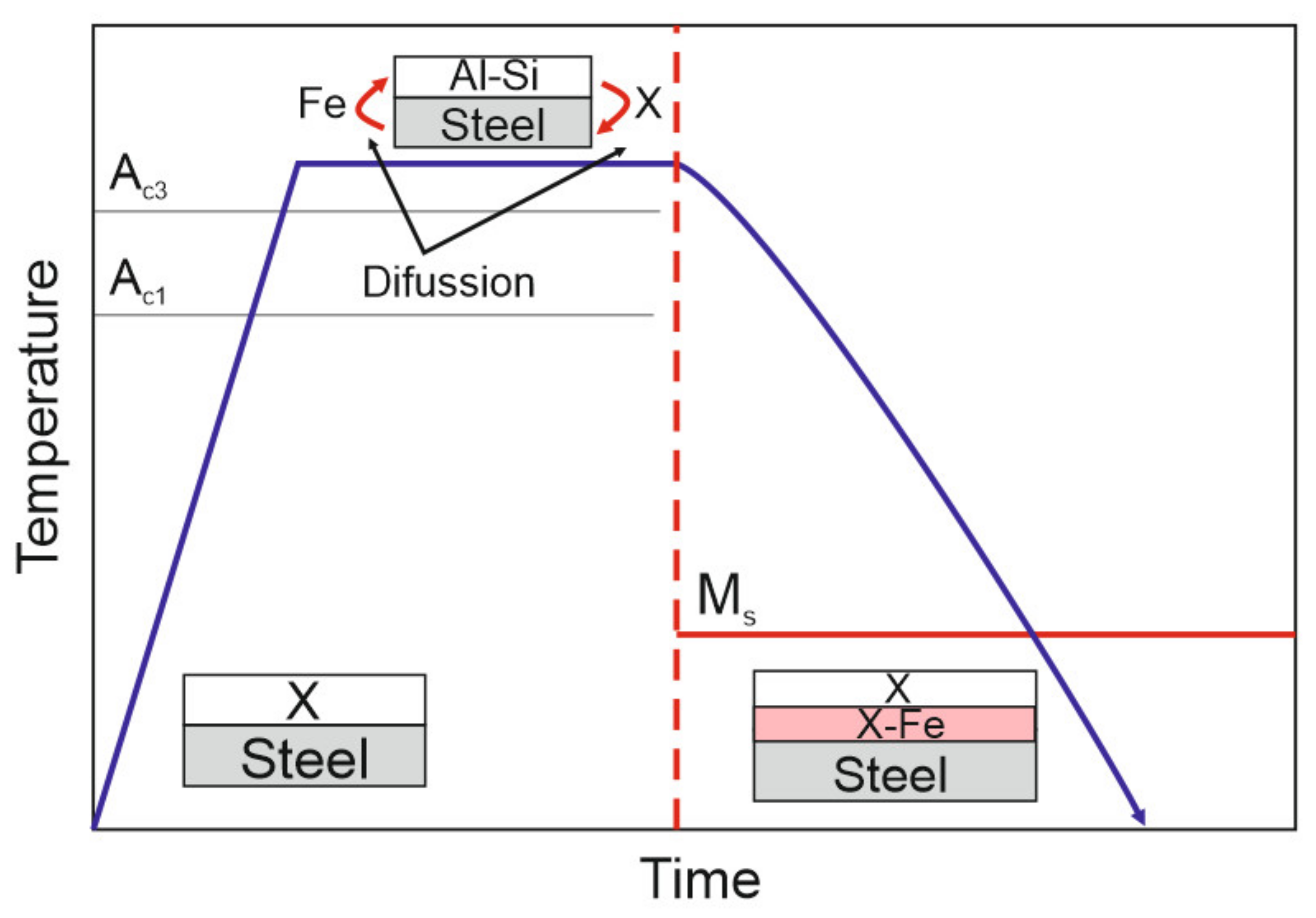
Currently, the most often used coating is AlSi coat, which gives the corrosion protection. Zn coating shows additionally cathodic protection. However, it may require indirect hot stamping followed by sandblasting [1]. When steel sheets are heated to an austenitization temperature, diffusion processes take place, leading to the formation of iron-enriched layers (Figure 14), improving the layer coating adhesion. A summary of currently used coatings is presented in Table 4.
7. Perspective Materials for Hot Stamping
Recently, a new approach is being considered, aimed at introducing new groups of advanced steels to the hot stamping technology [50]:
- stainless steels
- dual phase and multiphase steels
- medium-Mn steels
- sandwich materials
Stainless steels, being corrosion resistant and not requiring coatings and protective atmospheres during production, represent an interesting candidate for the production of hot-stamped elements [51]. Santacreu et al. [52] showed a hot stamping process of ferritic stainless steel (Table 5), which resulted in a 100% martensitic part and final properties: YS~860 MPa, UTS~1200 MPa and elongation over 10%. According to Herbelin [51], almost complete martensitic transformation can be performed at very low cooling rates (even 1 °C/s). This allows for air hardening and to perform multi-step forming operation. Fröhlich [53] showed that it is possible to obtain YS of 1100–1300 MPa, UTS of 1700-1850 MPa combined with elongation of 12–16%. Such material can be used in both intrusion resistance and energy absorbing components. This material exhibits duplex martensitic-austenitic microstructure.
Multiphase steels, including DP (dual phase) steels, are taken into account in new hot stamping approaches. The intercritical annealing for such steels is performed directly before forming and quenching. Austenite in the α-γ structure transforms during cooling to martensite, which results in typical duplex-type microstructures. Naderi et al. [55] investigated the feasibility of warm stamping of 0.14C–1.71Mn–0.55 at 640 °C in comparison to typical cold forming followed by quenching from 950 °C. The UTS of final element was lowered to 930 MPa (Table 5). However, the total elongation increased from 5% to 19% [5].
Another group of newly introduced to hot stamping steels are medium-Mn steels containing 3–12% of Mn [6,8,56]. They show some superior features compared to typical steels used in this technology: increased Mn addition decreases the Ac3 temperature, which allows to save some energy during material heating [57]; as Mn increases strongly hardenability, the parts may be air cooled and multiple stage forming may be performed [58,59]. Medium-Mn steels are designed to contain duplex austenitic-ferritic microstructure, which improves the mechanical properties. Rana et al. [54] obtained UTS levels of 1330–1450 MPa with TEl of 15–25 % for steel containing 0.12 C, 9.8 Mn, 1.4 Al, and 0.2 Si (wt. %).
8. Current Challenges of Hot Stamping
The literature review shows that the two major trends in the development of hot stamping are the advanced materials [2,6,7,8] and their heat treatment On the one hand, the aim is to additionally increase the strength [26] of finished parts, either by increasing the C content in steel or by producing elements with more advanced geometry. On the other hand, there are also visible trends, in which the plasticity of the material [52], and therefore the energy absorption possibilities [5], comes to the fore. This development bipolarity may result in a much greater applicability of elements produced by using this method than it is today. The use of more complex heat treatment, either before [55] or after [33] the forming process (tempering, tailoring), is an interesting aspect of this technology with great potential. The production of local, customized parts is a step forward in both science and technology. The development trends indicated above, however, introduce a lot of difficulties to the process, both affecting the appearance of the technological line and the design and simulation process preceding production [31]. Hot stamping, despite several decades of development, still faces many research problems, which are caused by the technology complexity. The most important issues include:
- -
- Multi-step heat treatment of steels newly introduced to hot stamping. Conventional heat treatment of hot stamped steels can be carried out with the use of typical furnaces [1], as it consists of simple annealing at a given temperature. In the case of modern processing methods, a multi-stage process is necessary, where individual temperatures and holding times are of key importance [55]. This is connected with the necessity to expand hot stamping technological lines with more advanced heat treatment sections/equipment.
- -
- Construction of material models [60] of new steels (eg. Usibor 2000, MBW 1900): There are no dedicated models to simulate hot stamping processes for new types of materials and their development is laborious and very expensive.
- -
- Analysis of the wear of dies and punches (heat consumption) during the simulation of stamping processes [61]. In particular, during the simulation of drawpieces from thick sheets, thicker than 3 mm, there is accelerated wear of the tools. Some methods of predicting die and punch regions, where accelerated heat wear occurs, based on methods used in forging, are needed. The areas with potentially increased wear could be padded with special alloys, which should provide increased die wear resistance.
- -
- Selection of the friction coefficient between the die and a form for new types of coatings [61]. For this purpose, it is necessary to perform experimental tests to determine the friction coefficient.
- -
- Analysis of hardening deformations [62] of car body parts (e.g., door ring, double door ring, floor panels, etc.). These are produced from laser-welded flat forms of various types of steel and thicknesses. The part is next heated in a large furnace, then shaped and hardened in a die. The main production problems are the complex tooling of the robot for transferring the form from the furnace to the press and from the press to the delivery table. Another problem is the laser cutting of the extrudate after the embossing process. Problems arise from the large dimensions and complicated shape of these stampings.
- -
- Hot stamping methods for large-sized [63] car body parts (e.g., door ring, double door ring, floor panels, etc.). These are produced from laser-welded flat forms of various types of steel and of various thicknesses. The part is next heated in a large furnace, then shaped and hardened in a die. The main production problems are the complex tooling of the robot for transferring the form from the furnace to the press and from the press to the delivery table. Another problem is the laser cutting of the extrudate after the embossing process. Problems arise from the large dimensions and complicated shape of these stampings.
- -
- Hydrogen or biogas fired furnaces. The industry aims to reduce production costs in the hot stamping technology. Currently, a new type of fuel source is being tested [64]. Due to the initial stage of implementation, the technology causes many complications.
9. Conclusions
Technological and metallurgical aspects of hot stamping technology with numerical simulation and process automation are reviewed in the paper. Hot stamping, in addition to the development towards modern design methods and the entire process, also uses an increasing range of new materials. In addition to typical martensitic steels of various chemical composition, works are also being carried out towards the introduction of austenitic steels and multiphase steels. The most prospective advanced steels include dual phase steels with a wide range of mechanical properties due to a variety of ferritic-martensitic microstructures possible to be produced. Such steels should be designed as intrusion resistant parts. The future perspective includes medium-manganese steels with fine-grained mixtures of ferrite (martensite) and retained austenite, which are preferred for most critical energy absorption parts. The industry needs a wide range of coatings, each of them exhibiting advantages and disadvantages, which forces the choice of the coating depending on the intended use.
Hot stamping technology is fully automated and requires numerical modelling at each production step, including: heating-up, transport to stamping die, gravitation, holding in the tool, stamping, quenching, opening of the tool together, and final cooling of the drawpiece. The importance of the use of digital twins in hot stamping technology is underlined, which allows for the effective and cost-efficient transfer from the lab to real production lines. In order to achieve even greater benefits from hot stamping technology, efforts should be directed towards implementing modern materials from the family of high-strength steels for the automotive industry. In addition to optimizing the technological line itself in terms of efficiency and precision, this will allow the greatest progress of this technology.
Author Contributions
Conceptualization, I.W. and A.S.; methodology, I.W. and A.G.; software, I.W.; validation, I.W. and A.G.; formal analysis, A.S.; investigation, I.W.; resources, A.G.; data curation, I.W. and A.S.; writing—original draft preparation, I.W., A.S. and A.G.; writing—review and editing, A.G.; visualization, I.W.; supervision, A.G.; project administration, I.W. and A.G.; funding acquisition, A.G. All authors have read and agreed to the published version of the manuscript.
Funding
A. Skowronek acknowledges the financial support through the 10/010/BKM22 project, Faculty of Mechanical Engineering, Silesian University of Technology, Gliwice, Poland.
Institutional Review Board Statement
Not applicable.
Informed Consent Statement
Not applicable.
Data Availability Statement
Not applicable.
Conflicts of Interest
The authors declare no conflict of interest.
References
- Billur, E. Hot Stamping of Ultra High-Strength Steels; Springer: New York, NY, USA, 2018; ISBN 978-3-319-98868-9. [Google Scholar]
- Karbasian, H.; Tekkaya, A.E. A Review on Hot Stamping. Mater. Process. Technol. 2010, 210, 2103–2118. [Google Scholar] [CrossRef]
- Neugebauer, R.; Schieck, F.; Polster, S.; Mosel, A.; Rautenstrauch, A.; Schönherr, J.; Pierschel, N. Press Hardening—An Innovative and Challenging Technology. Archiv. Civ. Mech. Eng. 2012, 12, 113–118. [Google Scholar] [CrossRef]
- Gronostajski, Z.; Pater, Z.; Madej, L.; Gontarz, A.; Lisiecki, L.; Łukaszek-Sołek, A.; Łuksza, J.; Mróz, S.; Muskalski, Z.; Muzykiewicz, W.; et al. Recent Development Trends in Metal Forming. Archiv. Civ. Mech. Eng. 2019, 19, 898–941. [Google Scholar] [CrossRef]
- Tong, C.; Rong, Q.; Yardley, V.A.; Li, X.; Luo, J.; Zhu, G.; Shi, Z. New Developments and Future Trends in Low-Temperature Hot Stamping Technologies: A Review. Metals 2020, 10, 1652. [Google Scholar] [CrossRef]
- Aydin, H.; Essadiqi, E.; Jung, I.-H.; Yue, S. Development of 3rd Generation AHSS with Medium Mn Content Alloying Compositions. Mater. Sci. Eng. A 2013, 564, 501–508. [Google Scholar] [CrossRef]
- Dharavath, B.; Morchhale, A.; Singh, S.K.; Kotkunde, N.; Naik, M.T. Experimental Determination and Theoretical Prediction of Limiting Strains for ASS 316L at Hot Forming Conditions. Mater. Eng. Perform. 2020, 29, 4766–4778. [Google Scholar] [CrossRef]
- Li, S.; Luo, H. Medium-Mn Steels for Hot Forming Application in the Automotive Industry. Int. J. Miner. Metall. Mater. 2021, 28, 741–753. [Google Scholar] [CrossRef]
- Liu, S.; Long, M.; Zhang, S.; Zhao, Y.; Zhao, J.; Feng, Y.; Chen, D.; Ma, M. Study on the Prediction of Tensile Strength and Phase Transition for Ultra-High Strength Hot Stamping Steel. Mater. Res. Technol. 2020, 9, 14244–14253. [Google Scholar] [CrossRef]
- Zhou, W.Q.; Pan, L.B.; Hu, K.H.; Sun, W.H.; Han, R.D. Effect of Original Microstructure on Microstructure and Mechanical Properties of High Strength Steel WHF1500H during Hot Forming. Mater. Sci. Forum 2018, 941, 206–211. [Google Scholar] [CrossRef]
- Autoform Help System. Available online: https://servicecenter.autoform.com (accessed on 10 April 2022).
- Trzepiecinski, T.; Lemu, H.G. Recent Developments and Trends in the Friction Testing for Conventional Sheet Metal Forming and Incremental Sheet Forming. Metals 2020, 10, 47. [Google Scholar] [CrossRef] [Green Version]
- Sajan, M.; Amirthalingam, M.; Chakkingal, U. A Novel Method for the Spring-Back Analysis of a Hot Stamping Steel. Mater. Res. Technol. 2021, 11, 227–234. [Google Scholar] [CrossRef]
- Huang, F.; Chen, Q.; Ding, H.; Wang, Y.; Mou, X.; Chen, J. Automotive Steel with a High Product of Strength and Elongation Used for Cold and Hot Forming Simultaneously. Materials 2021, 14, 1121. [Google Scholar] [CrossRef]
- Derazkola, H.A.; García Gil, E.; Murillo-Marrodán, A.; Méresse, D. Review on Dynamic Recrystallization of Martensitic Stainless Steels during Hot Deformation: Part I—Experimental Study. Metals 2021, 11, 572. [Google Scholar] [CrossRef]
- Xu, L.; Chen, L.; Chen, G.; Wang, M. Hot Deformation Behavior and Microstructure Analysis of 25Cr3Mo3NiNb Steel during Hot Compression Tests. Vacuum 2018, 147, 8–17. [Google Scholar] [CrossRef]
- Kong, H.; Chao, Q.; Rolfe, B.; Beladi, H. One-Step Quenching and Partitioning Treatment of a Tailor Welded Blank of Boron and TRIP Steels for Automotive Applications. Mater. Des. 2019, 174, 107799. [Google Scholar] [CrossRef]
- Omer, K.; ten Kortenaar, L.; Butcher, C.; Worswick, M.; Malcolm, S.; Detwiler, D. Testing of a Hot Stamped Axial Crush Member with Tailored Properties—Experiments and Models. Impact Eng. 2017, 103, 12–28. [Google Scholar] [CrossRef]
- Tang, B.T.; Bruschi, S.; Ghiotti, A.; Bariani, P.F. Numerical Modelling of the Tailored Tempering Process Applied to 22MnB5 Sheets. Finite Elem. Anal. Des. 2014, 81, 69–81. [Google Scholar] [CrossRef]
- Podany, P.; Reardon, C.; Koukolikova, M.; Prochazka, R.; Franc, A. Microstructure, Mechanical Properties and Welding of Low Carbon, Medium Manganese TWIP/TRIP Steel. Metals 2018, 8, 263. [Google Scholar] [CrossRef] [Green Version]
- Grajcar, A.; Różański, M.; Kamińska, M.; Grzegorczyk, B. Effect of Gas Atmosphere on the Non-Metallic Inclusions in Laser-Welded Trip Steel with Al and Si Additions. Mater. Tehnol. 2016, 50, 945–950. [Google Scholar] [CrossRef]
- Grajcar, A.; Lesz, S. Influence of Nb Microaddition on a Microstructure of Low-Alloyed Steels with Increased Manganese Content. Mater. Sci. Forum 2012, 706–709, 2124–2129. [Google Scholar] [CrossRef]
- Naderi, M.; Ketabchi, M.; Abbasi, M.; Bleck, W. Analysis of Microstructure and Mechanical Properties of Different Boron and Non-Boron Alloyed Steels after Being Hot Stamped. Procedia Eng. 2011, 10, 460–465. [Google Scholar] [CrossRef] [Green Version]
- So, H.; Faßmann, D.; Hoffmann, H.; Golle, R.; Schaper, M. An Investigation of the Blanking Process of the Quenchable Boron Alloyed Steel 22MnB5 before and after Hot Stamping Process. Mater. Process. Technol. 2012, 212, 437–449. [Google Scholar] [CrossRef]
- Lee, C.W.; Choi, W.S.; Cho, Y.R.; De Cooman, B.C. Microstructure Evolution of a 55wt.% Al–Zn Coating on Press Hardening Steel during Rapid Heating. Surf. Coat. Technol. 2015, 281, 35–43. [Google Scholar] [CrossRef]
- Li, Y.; Chen, Y.; Li, S. Phase Transformation Testing and Modeling for Hot Stamping of Boron Steel Considering the Effect of the Prior Austenite Deformation. Mater. Sci. Eng. A 2021, 821, 141447. [Google Scholar] [CrossRef]
- Zhang, R.; Shi, Z.; Yardley, V.A.; Lin, J. Experimental Studies of Necking and Fracture Limits of Boron Steel Sheet under Hot Stamping Conditions. Mater. Process. Technol. 2022, 302, 117481. [Google Scholar] [CrossRef]
- Çavuşoğlu, O.; Çavuşoğlu, O.; Yılmazoğlu, A.G.; Üzel, U.; Aydın, H.; Güral, A. Microstructural Features and Mechanical Properties of 22MnB5 Hot Stamping Steel in Different Heat Treatment Conditions. Mater. Res. Technol. 2020, 9, 10901–10908. [Google Scholar] [CrossRef]
- Couto, C.P.; Revilla, R.I.; Politano, R.; Costa, I.; Panossian, Z.; De Graeve, I.; Rossi, J.L.; Terryn, H. Influence of Austenitisation Temperatures during Hot Stamping on the Local Electrochemical Behaviour of 22MnB5 Steel Coated with Hot-Dip Al-Si. Corros. Sci. 2021, 190, 109673. [Google Scholar] [CrossRef]
- Merklein, M.; Lechler, J.; Stoehr, T. Investigations on the Thermal Behavior of Ultra High Strength Boron Manganese Steels within Hot Stamping. Int. J. Mater. Form. 2009, 2, 259. [Google Scholar] [CrossRef]
- Zhou, J.; Yang, X.; Mu, Y.; Liu, S.; Wang, B. Numerical Simulation and Experimental Investigation of Tailored Hot Stamping of Boron Steel by Partial Heating. Mater. Res. Technol. 2021, 14, 1347–1365. [Google Scholar] [CrossRef]
- Ji, Q.; Xu, Y.; Zhao, G.; Yang, G. Influence of Auto-Tempering on Mechanical Properties and Microstructure of 22MnB5 Hot Stamping Steel by Discontinuous Cooling Process. Ironmak. Steelmak. 2022, 49, 1–11. [Google Scholar] [CrossRef]
- Bao, L.; Wang, B.; You, X.; Li, H.; Gu, Y.; Liu, W. Numerical and Experimental Research on Localized Induction Heating Process for Hot Stamping Steel Sheets. Heat Mass Transf. 2020, 151, 119422. [Google Scholar] [CrossRef]
- Abspoel, M.; Neelis, B.M.; van Liempt, P. Constitutive Behaviour under Hot Stamping Conditions. Mater. Process. Technol. 2016, 228, 34–42. [Google Scholar] [CrossRef]
- Merklein, M.; Lechler, J.; Geiger, M. Characterisation of the Flow Properties of the Quenchenable Ultra High Strength Steel 22MnB5. CIRP Ann. 2006, 55, 229–232. [Google Scholar] [CrossRef]
- Bardelcik, A.; Worswick, M.J.; Winkler, S.; Wells, M.A. A Strain Rate Sensitive Constitutive Model for Quenched Boron Steel with Tailored Properties. Impact Eng. 2012, 50, 49–62. [Google Scholar] [CrossRef]
- Caia, Y.; Halim, F.; Li, G.; Chen, S. Hot Stamping Simulation and Austenite Decomposition Modeling of an Automobile Cross Member. Procedia Eng. 2011, 15, 4902–4907. [Google Scholar] [CrossRef] [Green Version]
- Behrens, B.A.; Olle, P. Numerische Simulation Des Presshärtprozesses Unter Berücksichtigung Der Gefügeumwandlung; Institut für Umformtechnik und Umformmaschinen: Frankenthal, Germany, 2007. [Google Scholar]
- Hochholdinger, B. Simulation Des Presshärteprozesses Und Vorhersage Der Mechanischen Bauteileigenschaften Nach Dem Härten; ETH Zurich: Zurich, Switzerland, 2012. [Google Scholar]
- Tang, B.T.; Bruschi, S.; Ghiotti, A.; Bariani, P.F. An Improved Damage Evolution Model to Predict Fracture of Steel Sheet at Elevated Temperature. Mater. Process. Technol. 2016, 228, 76–87. [Google Scholar] [CrossRef]
- Lemaitre, J.; Chaboche, J.-L. Mechanics of Solid Materials; Cambridge University Press: Cambridge, UK, 1990. [Google Scholar]
- Hung, T.-H.; Tsai, P.-W.; Chen, F.-K.; Huang, T.; Liu, W.-L. Measurement of Heat Transfer Coefficient of Boron Steel in Hot Stamping. Procedia Eng. 2014, 81, 1750–1755. [Google Scholar] [CrossRef] [Green Version]
- Salomonsson, P.; Oldenburg, M. Investigation of Heat Transfer in the Press Hardening Process. In Proceedings of the International Conference on Hot Sheet Metal Forming of High-Performance Steel, Luleå, Sweden, 15–17 June 2009. [Google Scholar]
- Hay, B.; Bourouga, B.; Dessain, C. Thermal Contact Resistance Estimation at the Blank/Tool Interface: Experimental Approach to Simulate the Blank Cooling during the Hot Stamping Process. Mater. Form. 2010, 3, 147–163. [Google Scholar] [CrossRef]
- Hu, P.; Ying, L.; Li, Y.; Liao, Z. Effect of Oxide Scale on Temperature-Dependent Interfacial Heat Transfer in Hot Stamping Process. Mater. Process. Technol. 2013, 213, 1475–1483. [Google Scholar] [CrossRef]
- Ying, L.; Gao, T.; Dai, M.; Hu, P.; Shen, L. Investigation of Convection Heat Transfer Coefficient of Circular Cross-Section Short Pipes in Hot Stamping Dies. Appl. Therm. Eng. 2018, 138, 133–153. [Google Scholar] [CrossRef]
- Wang, J.; Hyland, R.W. Zinc Coated Steel with Inorganic Overlay for Hot Forming. US20120118437A1, 17 May 2012. [Google Scholar]
- Choi, W.S.; De Cooman, B.C. Characterization of the Bendability of Press-Hardened 22MnB5 Steel. Steel Res. Int. 2014, 85, 824–835. [Google Scholar] [CrossRef]
- Chang, J.-K.; Lin, C.-S.; Cheng, W.-J.; Lo, I.-H.; Wang, W.-R. Oxidation Resistant Silane Coating for Hot-Dip Galvanized Hot Stamping Steel. Corros. Sci. 2020, 164, 108307. [Google Scholar] [CrossRef]
- Liang, J.; Lu, H.; Zhang, L.; Li, F.; Cao, R.; Liu, K.; Pan, H.; Teng, H.; Li, X.; Guo, A.; et al. A 2000 MPa Grade Nb Bearing Hot Stamping Steel with Ultra-High Yield Strength. Mater. Sci. Eng. A 2021, 801, 140419. [Google Scholar] [CrossRef]
- Herbelin, J.M. 1000–2000 MPaMartensitic Stainless Steels for Flexible Hot Forming Processes. In Proceedings of the 1000–2000 MPaMartensitic Stainless Steels for Flexible Hot Forming Processes, Bad Nauheim, Germany, 13 May 2014. [Google Scholar]
- Santacreu, P.; Badinier, G.; Moreau, J.-B.; Herbelin, J.-M. Fatigue Properties of a New Martensitic Stainless Steel for Hot Stamped Chassis Parts; SAE Technical Paper; SAE International: Warrendale, PA, USA, 2015; Volume 2015. [Google Scholar] [CrossRef]
- Fröhlich, T. Maximum Safety and Lightweight Potential Due to Use of New High Strength Steels. In Proceedings of the Outokumpu Experience 2013 Conference, London, UK, 22–23 May 2013. [Google Scholar]
- Speer, J.; Rana, R.; Matlock, D.; Glover, A.; Thomas, G.; De Moor, E. Processing Variants in Medium-Mn Steels. Metals 2019, 9, 771. [Google Scholar] [CrossRef] [Green Version]
- Naderi, M.; Ketabchi, M.; Abbasi, M.; Bleak, W. Semi-Hot Stamping as an Improved Process of Hot Stamping. Mater. Sci. Technol. 2011, 27, 369–376. [Google Scholar] [CrossRef]
- Tong, C.; Zhu, G.; Rong, Q.; Yardley, V.A.; Shi, Z.; Li, X.; Luo, J.; Lin, J. Investigation of Austenitising Behaviour of Medium-Mn Steel in the Hot-Stamping Heating Process. Mater. Process. Technol. 2021, 297, 117269. [Google Scholar] [CrossRef]
- De Moor, E.; Matlock, D.K.; Speer, J.G.; Merwin, M.J. Austenite Stabilization through Manganese Enrichment. Scr. Mater. 2011, 64, 185–188. [Google Scholar] [CrossRef]
- Skowronek, A.; Morawiec, M.; Kozłowska, A.; Pakieła, W. Effect of Hot Deformation on Phase Transformation Kinetics in Isothermally Annealed 3Mn-1.6Al Steel. Materials 2020, 13, 5817. [Google Scholar] [CrossRef]
- Lee, Y.-K.; Han, J. Current Opinion in Medium Manganese Steel. Mater. Sci. Technol. 2015, 31, 843–856. [Google Scholar] [CrossRef]
- Hein, P.; Wilsius, J. Status and Innovation Trends in Hot Stamping of USIBOR 1500 P. Steel Res. Int. 2008, 79, 85–91. [Google Scholar] [CrossRef]
- Schwingenschlögl, P.; Niederhofer, P.; Merklein, M. Investigation on Basic Friction and Wear Mechanisms within Hot Stamping Considering the Influence of Tool Steel and Hardness. Wear 2019, 426–427, 378–389. [Google Scholar] [CrossRef]
- Wróbel, I.; Graboś, A. Numerical Compensation of Torsional Hardening Deformations of Parts Made by Hot Stamping. Mechanik 2018, 91, 904–906. [Google Scholar] [CrossRef] [Green Version]
- Wang, C.; Li, X.; Han, S.; Zhang, L.; Chang, Y.; Cao, W.; Dong, H. Warm Stamping Technology of the Medium Manganese Steel. Steel Res. Int. 2018, 89, 1700360. [Google Scholar] [CrossRef]
- Advancements in Furnace Design Improve Hot Stamping. Available online: https://www.thefabricator.com/stampingjournal/article/stamping/advancements-in-furnace-design-improve-hot-stamping (accessed on 29 April 2022).
Figure 1.
Evolution of microstructure and mechanical properties in the hot-stamping process; YS—yield strength, UTS—ultimate tensile strength, El-elongation.
Figure 1.
Evolution of microstructure and mechanical properties in the hot-stamping process; YS—yield strength, UTS—ultimate tensile strength, El-elongation.

Figure 2.
Scheme of the hot stamping process: (a) direct and (b) indirect.

Figure 3.
Steel sheets of varying thickness along their length: (a) Tailor Rolled Blanks, (b) Tailor Welded Blanks.
Figure 3.
Steel sheets of varying thickness along their length: (a) Tailor Rolled Blanks, (b) Tailor Welded Blanks.

Figure 4.
Drawpiece with reinforcing patch.

Figure 5.
Digital twin of the hot stamping line.

Figure 6.
Fragment of the automated hot stamping line.

Figure 7.
Typical tensile curves and corresponding microstructures for advanced multiphase steels; TR—thermomechanically rolled, IA—intercritically annealed, M—martensite, B—bainite, RA—retained austenite.
Figure 7.
Typical tensile curves and corresponding microstructures for advanced multiphase steels; TR—thermomechanically rolled, IA—intercritically annealed, M—martensite, B—bainite, RA—retained austenite.

Figure 8.
Influence of cooling rate (a) and soaking temperature (b) on microstructure of high-strength steels.
Figure 8.
Influence of cooling rate (a) and soaking temperature (b) on microstructure of high-strength steels.

Figure 9.
Stamping die with heated segments and water-cooled segments.

Figure 10.
Use of laser beam to generate soft zones in B pillar.

Figure 11.
An example of FEM simulation stages of the hot stamping process.

Figure 12.
A range of generated strengthening curves for the different phases of 22MnB5 steel determined in a wide range of temperatures (between 20 and 850 °C) and strain rates (between 0.01 and 10 s−1).
Figure 12.
A range of generated strengthening curves for the different phases of 22MnB5 steel determined in a wide range of temperatures (between 20 and 850 °C) and strain rates (between 0.01 and 10 s−1).

Figure 13.
Dependency of the heat transfer coefficient (HTC) as a function of the gap and the pressure between die and blank.
Figure 13.
Dependency of the heat transfer coefficient (HTC) as a function of the gap and the pressure between die and blank.

Figure 14.
Diffusion changes taking place in the coating in the subsequent stages of the technological process of hot stamping of steel sheets; X—coating element.
Figure 14.
Diffusion changes taking place in the coating in the subsequent stages of the technological process of hot stamping of steel sheets; X—coating element.


Table 1.
Influence of the alloying elements on phase transformations during cooling of classical Mn-B steel.
Table 1.
Influence of the alloying elements on phase transformations during cooling of classical Mn-B steel.
| Effect | Chemical Element | ||||||
|---|---|---|---|---|---|---|---|
| C | Mn | B | Si | Cr | Mo | Nb | |
| Ferritic transformation delay | X | X | X | X | X | ||
| Acceleration of the ferritic transformation | X | X | |||||
| Pearlitic transformation delay | X | X | X | X | |||
| Bainite transformation delay | X | X | X | X | |||
| Decrease of the Ms Temperature | X | X | |||||
Table 2.
Chemical composition and typical mechanical properties of 22MnB5 steel, based on [2,25]; HS—hot stamping, TEl—total elongation.
| Chemical Element, wt. % | |||||||
|---|---|---|---|---|---|---|---|
| C | Mn | B | Cr | Si | Al | Ti | N |
| 0.19–0.22 | 1.10–1.40 | 0.0008–0.0050 | 0.10–0.35 | 0.00–0.40 | 0.02–0.04 | 0.015–0.050 | 0.00–0.01 |
| Mechanical properties | |||||||
| Initial | After HS | ||||||
| YS, MPa | UTS, MPa | TEl, % | YS, MPa | UTS, MPa | TEl, % | ||
| ~400 | ~600 | ~22 | ~1000 | ~1500 | ~5 | ||
Table 3.
Carbon content and typical mechanical properties of higher-C contents Mn-B steels used for hot stamping; based on [2].
Table 3.
Carbon content and typical mechanical properties of higher-C contents Mn-B steels used for hot stamping; based on [2].
| Steel Grade | Carbon Content, wt, % | Initial | After HS | ||
|---|---|---|---|---|---|
| YS, MPa | UTS, MPa | YS, MPa | UTS, MPa | ||
| 27MnCrB5 | 0.25 | 478 | 638 | 1097 | 1612 |
| 28MnB5 | 0.28 | 420 | 620 | 1135 | 1740 |
| 30MnB5 | 0.30 | 510 | 700 | 1230 | 1740 |
| 33CrB5 | 0.33 | 420 | 620 | 1290 | 1850 |
| 34B5 | 0.34 | 600 | 820 | 1225 | 1919 |
| Coating Type | Advantages | Disadvantages |
|---|---|---|
| Uncoated steel |
|
|
| AlSi, AlSiFe |
|
|
| Zn, ZnFe |
|
|
| ZnNi, ZnNiFe |
|
|
| AlZn |
|
|
| ZnAlMg |
|
|
Table 5.
Perspective advanced steel grades for hot stamping.
| Steel | Chemical Composition, wt. % | Mechanical Properties | ||||||
|---|---|---|---|---|---|---|---|---|
| C | Mn | Cr | Al | Si | YS, MPa | UTS, MPa | TEl, % | |
| Santacreu et al. [52] | 0.10 | 0.4 | 12.0 | - | - | ~800 | ~1200 | >10 |
| Fröhlich [53] | 0.43–0.50 | <1.0 | 12.5–14.5 | - | - | 1100–1300 | 1700–1850 | 12–16 |
| Speer et al. [54] | 0.12 | 9.76 | - | 1.37 | 0.19 | 750–1100 | 1330–1450 | 15–25 |
| Naderi et al. [55] | 0.14 | 1.71 | 0.55 | 0.02 | 0.12 | 400 | 930 | ~20 |
Publisher’s Note: MDPI stays neutral with regard to jurisdictional claims in published maps and institutional affiliations. |
© 2022 by the authors. Licensee MDPI, Basel, Switzerland. This article is an open access article distributed under the terms and conditions of the Creative Commons Attribution (CC BY) license (https://creativecommons.org/licenses/by/4.0/).
Share and Cite
MDPI and ACS Style
Wróbel, I.; Skowronek, A.; Grajcar, A. A Review on Hot Stamping of Advanced High-Strength Steels: Technological-Metallurgical Aspects and Numerical Simulation. Symmetry 2022, 14, 969. https://0-doi-org.brum.beds.ac.uk/10.3390/sym14050969
AMA Style
Wróbel I, Skowronek A, Grajcar A. A Review on Hot Stamping of Advanced High-Strength Steels: Technological-Metallurgical Aspects and Numerical Simulation. Symmetry. 2022; 14(5):969. https://0-doi-org.brum.beds.ac.uk/10.3390/sym14050969
Chicago/Turabian StyleWróbel, Ireneusz, Adam Skowronek, and Adam Grajcar. 2022. "A Review on Hot Stamping of Advanced High-Strength Steels: Technological-Metallurgical Aspects and Numerical Simulation" Symmetry 14, no. 5: 969. https://0-doi-org.brum.beds.ac.uk/10.3390/sym14050969
Note that from the first issue of 2016, this journal uses article numbers instead of page numbers. See further details here.