Spiral Mobility Based on Optimized Clustering for Optimal Data Extraction in WSNs


School of Computer Science and Technology, Dalian University of Technology, Dalian 116000, China
*
Author to whom correspondence should be addressed.
Technologies 2018, 6(1), 35; https://0-doi-org.brum.beds.ac.uk/10.3390/technologies6010035
Submission received: 12 January 2018
/
Revised: 18 March 2018
/
Accepted: 18 March 2018
/
Published: 20 March 2018
(This article belongs to the Section Information and Communication Technologies)
Abstract
:Wireless Sensor Networks (WSNs) have led to tremendous growth in the development of sensor technology and offer numerous applications, such as wildlife monitoring, environment, healthcare, military surveillance and security systems. In terms of performance, the evolutions of WSN routing protocols play a vital role in extending the lifetime of networking operations. Due to the limited resources of power in sensor nodes, the design and implementation of an energy-efficient routing protocol comprise a key challenge for researchers. Before, in the case of a static sink, nodes at farther areas from the sink transmit their sensed data at a longer transmission range and die early, while nearby nodes face lesser transmission costs and stay alive for a longer period. This unbalanced energy distribution creates energy holes in ares far from the sink in WSNs. Mobility-based sink routing protocols are proposed to minimize the sub-optimal energy consumption in WSNs, as the sink mobility covers the sensor field, which alleviates the overall load-balancing among sensor nodes. In order to overcome the energy hole issue while prolonging the network lifetime, it is important to determine the optimal mobility pattern. In this regard, we propose the Spiral Mobility based on Optimized Clustering (SMOC) routing protocol and the Multiple sink-based SMOC (M-SMOC) routing protocol for large-scale WSNs. Performance evaluations of the proposed protocols are compared with various existing routing protocols based on static sink, random mobility and grid mobility. Different numbers of performance parameters are considered for evaluation, such as network lifetime, network stability, packet drop ratio, packet delivery ratio, end-to-end delay, average energy consumption, network connection time and the impact of different heterogeneity levels. Experimental results show the benefits of the spiral mobility pattern and how it improves the network lifetime and stability period over the existing state-of-the-art routing protocols.
1. Introduction
In recent years, the development of smart sensors in real-world applications has given traction to the progression of Wireless Sensor Networks (WSNs). WSNs consists of micro-sensors with the capability of monitoring environmental and physical factors, such as humidity, seismic events, temperature, motions, vibrations, etc. [1]. These sensors are smart, intelligent, inexpensive and small-sized nodes, to which is owed the drastic enhancement in the development of Micro-Electrical Mechanical Systems (MEMS) [2]. A typical sensor node consists of a sensing unit, power unit, processing unit and radio unit; cumulatively, these sensor nodes are deployed over a chosen area of interest in a structured or unstructured manner [3].
Various factors influence the design of WSNs, such as scalability, fault tolerance, hardware constraint, operating environment and power. Researchers always try to overcome all these issues, but due to the limited energy resources, they mainly focus on the power constraint to design an energy-efficient routing protocol [4].
By studying the existing schemes, it is noticed that the clustering technique is effective among the location-based and flat routing techniques [5]. It organizes the sensor nodes into clusters by dividing the sensor field and allows sensor nodes to transmit data to the Cluster Head (CH), which is responsible for data transmission towards the sink. Various clustering routing protocols are proposed in order to maximize the network lifetime using a static sink, but the traditional static sink has some limitations [6].
Before mobility schemes, these static networks were easy to manage and maintain due to the small variation in the network topologies, which simplified the challenges occurring at different levels [7]. These static sink-based WSNs were found defective recently in large-scale networks because nodes that are near the static sink act as relays for the nodes that are far from sink. Therefore, these nodes lose their energy very quickly, and this causes the energy hole problem in the sensor field and results in premature disconnection of the network [8]. Due to the death of nodes, the sink gets isolated from the other nodes that are alive and functioning properly. A WSN with multiple static sinks is proposed to solve this issue, but the issue remains the same for large-scale networks due to the huge amount of sensor nodes in the field and the few static sinks at constant locations in the network [9].
Much effort has been devoted to designing energy-efficient mobile sink base routing protocols. This extra property of mobility can enhance the performance of the network in real-time scenarios due to the constant movement of the sink over the network, which leads to less packet drops and extends the network lifetime because of the short-range communication throughout the network [10]. Furthermore, the sink moves over the entire network field and collects the sensed information, which alleviates the energy hole problem from the network [11]. For this reason, sink mobility is exploited in WSNs with promising advancement in the performance of the network lifetime. In order to obtain the maximum advantage and cross-check the performance of mobility-based routing protocols, it is better to determine the suitable mobility pattern [12]. A routing protocol should accurately represent the mobility pattern and utilize the network energy resources in an efficient manner. Controlled and uncontrolled mobility schemes were proposed in the past, whereas uncontrolled mobility was mostly based on random mobility, while controlled mobility has different variations such as grid mobility [13]. Random mobility is one the earliest mobility patterns, and different versions of this mobility pattern were proposed in the past; however, it has many flaws, such as nodes are unfamiliar with the location of the sink during the whole network lifetime, which increased the packet drop ratio. Furthermore, during the critical data transmission, sensor nodes dissipate more energy due to the long-distance transmission. The grid mobility pattern is an enhancement of random mobility; though grid mobility provides promising results in small-scale networks, the problem with this pattern of sensor nodes is that is has to wait for a longer period for the mobile sink in large networks [14]. The mobile sink covers the whole network area and moves on a defined mobility pattern, which results in huge data loss in farther areas. Furthermore, in the case of critical data reporting, the grid mobility pattern is not a suitable solution.
In this paper, we develop a novel optimized clustering framework to investigate the effects of sink mobility. Furthermore, we propose two routing protocols based on the spiral mobility pattern: Spiral Mobility based on Optimized Clustering (SMOC) for optimal data extraction and Multiple sink based on SMOC (M-SMOC) for large-scale WSNs. In SMOC, a single mobile sink moves in a spiral pattern over the sensing field to collect data from sensor nodes and CHs, while in M-SMOC, four mobile sinks move in the spiral pattern over the sensing field to cover the whole network area and avoid the delay in long-range communication with CHs. The major contributions of our proposed protocols are as follows.
- The proposed SMOC and M-SMOC routing protocols allow each node to communicate directly with the sink for the critical data reporting, if the distance between the node and CH is greater than the distance between the node and sink. The proposed spiral mobility pattern for the sink covers the whole network area and resolves the energy hole problem.
- We have simulated our proposed models and compared them with state-of-the-art routing protocols, which offer mobility and achieve encouraging results. We performed extensive simulations in order to analyze our proposed models and included some satisfactory outcomes in this paper.
The rest of the paper is organized as follows. Section 2 contains a brief literature review. System models and the problem statement are explained in Section 3. Section 4 describes the network design and methodology of spiral mobility for single and multiple sinks. The proposed model and technical details of routing techniques are given in Section 5. Experimental methodology and simulation results are presented in Section 6. The performance evaluation is discussed in Section 7. Conclusion and future work are given in Section 8.
2. Related Work
Currently, the existing literature focuses on developing energy-efficient routing protocols for WSNs that deal with the entire static network environment. Some of the recent research work took the initiative of proposing sink mobility with the existence of static nodes in order to collect information more accurately from the cluster-based self-organized sensor nodes. Sink mobility offers a unique opportunity to access the different network areas to avoid packet drops due to the longer distance transmissions of sensor nodes. In realization of this fact, several mobility-based energy-efficient routing protocols have been proposed recently. These protocols are based on different mobility patterns moving in the sensor field. All of these protocols are classified into two main schemes: controlled mobility pattern and uncontrolled mobility pattern. In [20], the controlled mobility pattern, speed or direction of the sink can be controlled and managed by the end-user according to the variation in the network; whilst in the uncontrolled mobility pattern, the sink changes the speed or direction autonomously, which causes unknown time for CHs’ communication with the sink [21]. This paper considers the spiral-based controlled mobility pattern. We briefly describe the related work in this context including the strengths and weakness of their methodologies in the following paragraph.
An Intelligent Agent-based Routing (IAR) [22] protocol is developed to reduce signal overhead and efficient data delivery to the sink. The authors choose some sensor nodes as agents, and the sink visits the sensor field. At the time when the sink arrives in the range of agents, agents start transmitting data to the sink. If the sink is not in the range, then the sink chooses a provisional node as a relay node, which receives information from the agent and transmits it to the sink. To prolong the network lifetime, a Mobile Sink-based Routing Protocol (MSRP) [23] is proposed. The sink moves to the top of the highest energy node in a cluster and receives data from that node. Introducing CHs as the root of a tree [24], when the mobile sink arrives in the sensor field, it will register itself with the nearest CH as a root; in this way, the CH will update other CHs with the route and location of the sink. When the sink arrives in a cluster, the CH only maintains the connection with the sink and evades the update to the root of the sink location. When the sink arrives in the next cluster, it will choose another agent node, which will be a new CH; this CH shares the information about the location of the sink according to the root and other nodes. It appears to be a good technique for reducing the overhead of clusters because of multi-hopping. However, the root node plays an important role in route management, which causes a quick reduction of the energy and reduces the network lifetime. A hierarchical cluster architecture (HCDD) [25] is proposed to introduce the second level CHs, named as the agents. These agent CHs are chosen to keep track of the sink location and route selection. All the data from CHs are routed to the closest agent, and when the sink moves in the sensor field, it informs the closest agent via the nearest CH. Upon the arrival of the sink, the agent broadcasts the sink location to all the other agents using inter-agent communication. Due to this high mobility pattern, the HCDD node utilizes more energy, which causes the quick death of the network. Moreover, limited broadcasting of the sink location can cause high latency. A predetermined trajectory is proposed [26], in which the author utilizes multiple sinks on a predefined trajectory where mobile sinks move along the lines of a hexagonal tiling and stop for a predefined specific time at six and twelve different points for data collection. It appears to be a good technique for network lifetime enhancement, but this technique utilizes direct transmission to the mobile sinks, which causes extra cost for farther nodes in terms of energy dissipation.
In contrast to the mobile sink, various data aggregation techniques are proposed using a static sink where the network aggregation at intermediate nodes usually results in a reduction of data packets. In [27], the author discusses the problem of scheduling virtual data aggregation trees to maximize the network lifetime where the size of the data packet is fixed for the aggregation, named as the Maximum Lifetime Data Aggregation Tree Scheduling (MLDATS) problem. In this paper, the authors proposed a Local Tree Reconstruction-Based Scheduling Algorithm (LTRBSA) for the MLDATS problem. In addition, the authors showed that the MLDATS problem is NP-complete. In [28], the author proposed a distributed algorithm to find a backbone in the dual-radio network whenever a new backbone was needed; and examined the difficulty of constructing virtual backbones to increase the network lifetime.
As several energy-efficient algorithms are proposed with different cluster formations and mobility patterns, these research works provide the proper functional mathematical analysis [29]. These analyses provide the determination of the clustering range in diverse scenarios.
Based on the literature review, it is demonstrated that network performance can be enhanced with the proper mobility pattern of the sink. Moreover, energy consumption can be reduced with frequent broadcasting of the sink location to CHs.
The purpose of this research is to optimize the network, reduce the overall energy consumption and enhance the network lifetime with more stable data delivery in large-scale networks. Therefore, we propose the controlled spiral mobility pattern, offering a better solution in real-time network operations. This protocol neither requires complex algorithms for operations, nor imposes too many constraints on the sensor nodes. These characteristics of this controlled mobility pattern, in energy-efficient manner, make this protocol preferable in a huge range of WSN applications as compared to existing routing protocols.
3. System Models and Problem Statement
In order to design a better sensor network, the main factors include: network design, the schedule of the sensor node’s data delivery, the radio model and data aggregation techniques. Our proposed routing protocols achieve the aforementioned major objectives and produce a well-defined network.
3.1. Problem Statement
Based on the literature review, it is observed that most of the works are based on a static sink, random mobility and grid mobility, which lead to the inefficiency of the clustered topologies of their schemes. To prove this issue, we use the spiral mobility pattern based on optimized clustering technique, which provides stronger and more stable network. To verify our proposed models, we use simulations to prove how different ranges of clusters create variation in the network topology. Moreover, our concern in this study is to describe the effects of sink mobility patterns on the network lifetime. Specifically, the objective of this study is to seek solutions of these problems:
- What will be the features of mobile sink that can maximize the network lifetime?
- Which is a suitable mobility pattern based on the comparative results?
- If we compare the controlled mobility pattern with random mobility, how much improvement in the lifetime of the network can be achieved?
- Why is the grid mobility pattern not suitable for large-scale networks?
3.2. Assumptions
- The sink has knowledge about the complete network topology, including node positions and energy levels. It is also assumed that the sink has sufficient energy resources to perform computations to control the mobility and topology [30].
- The sink is equipped with GPS used for self-localization.
- After collecting the data from a given point, the sink moves to the next point within a specific amount of time defined by the network administrator.
- All nodes in the network are time synchronized, and various synchronization techniques such as; Time Division Multiple Access (TDMA) and Carrier Sense Multiple Access (CSMA) are specifically designed for WSNs with virtually no overhead and provide reasonable synchronization performance [31].
- The proposed routing protocol is organized into multiple rounds. Each round has a predefined time T = 1 min.
- The sensor node transmits data in packets, and each packet has (Packet Length) = 2048 bits (256 bytes).
- Energy consumption in communication is more than consumption in computation [32].
- Dissipated energy in the idle-mode of the sensor node can be negligible [33].
- To avoid interference between communications, a TDMA-based MAC (Media Access Control) protocol is assumed to be used in the communication phase.
- The overall energy dissipation over a single time period is divided into two categories, the actual communication energy cost and the network reconfiguration cost. As the actual communication includes all sensor nodes’ transmission towards the mobile sink over a dwelling time, so it dissipates the major portion of the energy of the sensor nodes. While reconfiguration of the network also causes some energy dissipation, this is a minor energy dissipation (less than 1.0%), and we consider it as a negligible energy cost [34].
Meanwhile, dense and larger sensor network areas demand a higher frequency of reconfiguration with the help of more complicated and sophisticated path-planning algorithms. These scenarios force designers to reconsider the reconfiguration’s cost to track the energy resources’ dissipation to ensure the performance of the implemented routing algorithm. This demands serious effort to keep routing algorithms simple to avoid complication and implement the calculated reconfigurations. Frequent reconfigurations can damage the cause of energy efficiency by rotating the communication responsibilities.
In this paper, we focus on a balanced reconfiguration frequency for our proposed models, while avoiding the unnecessary complication the cluster-formation algorithm and the mobility pattern of the sink. In the current proposed model, we have managed the reconfiguration cost by managing manual settings for a single communication period and data gathering method, but in the advanced implementation case, we are committed to developing most the economical reconfiguration system, which can be altered through online reprogramming of network nodes.
3.3. Energy Dissipation and Radio Models
In this paper, we use first order radio model for a fair comparison with previously-published protocols. Figure 1 shows the radio model used to measure energy dissipation in a heterogeneous network, which consists of three parts: the transmitter, amplifier and receiver.
Depending on the distance between the transmitter and receiver, both free space and multi-path fading models are used in the simulations [35]. Thus, to transmit a - message to a distance d, the mathematical representation of this message will be:
where is the energy consumption of processing the data by radio circuits and is the energy of radio amplification to compensate the path loss, while is the energy consumption by the amplifier and denotes the distance threshold. In order to receive this - message, the energy consumed by the receiver will be:
3.4. Heterogeneous Network Model
In this model, two types of nodes are deployed in the network: normal and advanced nodes. Zero-point-five Joules is set as the initial energy level for normal nodes , and advanced nodes have -times more energy than normal nodes. This will provide more stability in the network because the proposed model always selects the advanced node as a CH because of the higher energy level. Every advanced node will be selected as a CH, and those advanced nodes that are not selected as CHs in first round would have priority in the next round. Compared to normal nodes, more advanced nodes can be added to the network in order to prolong the stability period. There are advanced nodes with initial energy and , while normal nodes have initial energy . The total initial energy of the network can be calculated as:
4. Network Design
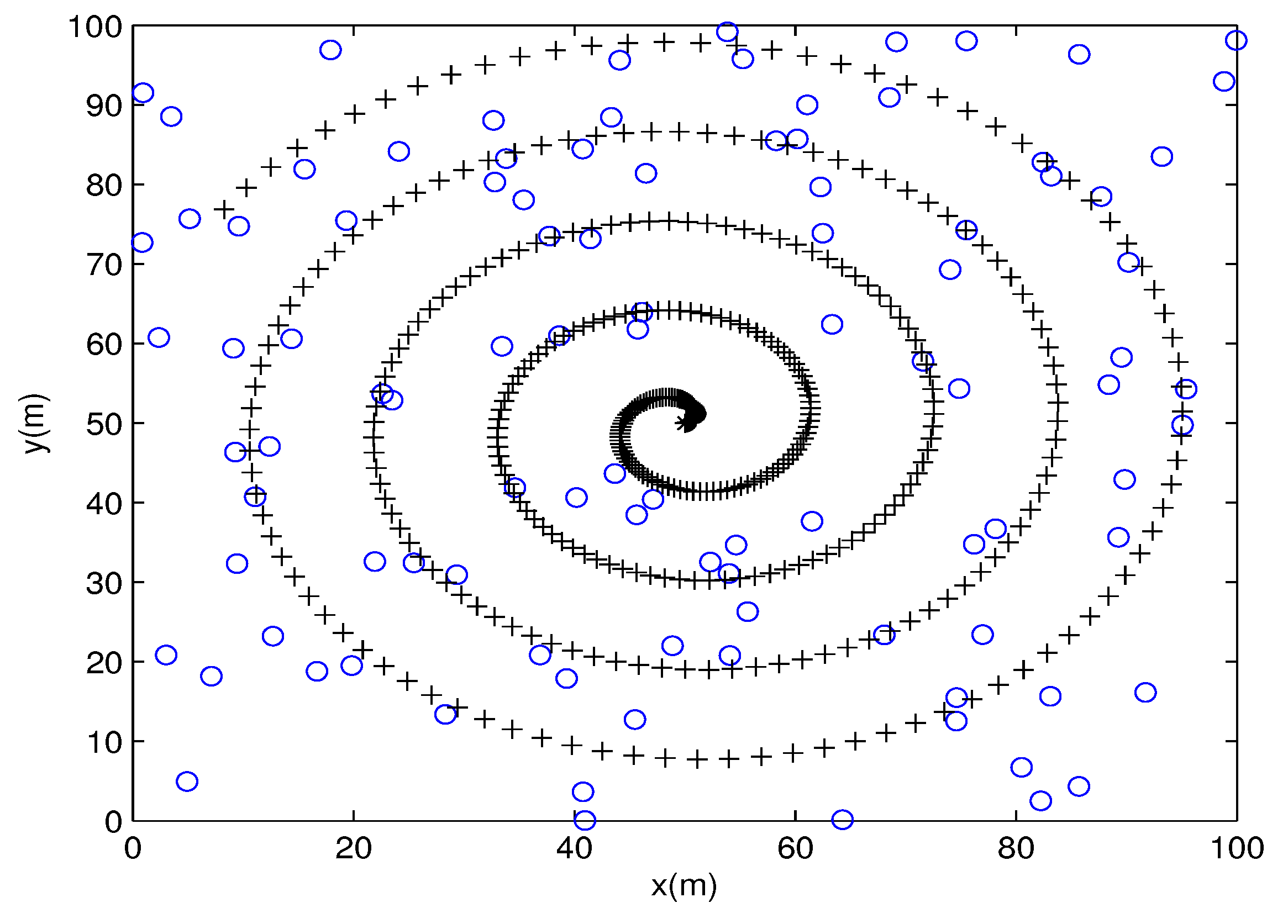
This section presents the detail and design of the network model to execute the proposed routing protocols. It is assumed that there are stationary sensor nodes randomly deployed in an X × Y sensor field. These sensor nodes sense the data from the sensing field and aim to transmit these reports towards the sink, while the sink is traveling on the network field with controlled mobility in a spiral pattern. Nodes are organized into a dynamic clustering hierarchy with a distributed heterogeneous cluster-formation property. CHs are chosen for their prospective cluster to receive data from member nodes and transmit them to the sink; moreover, these CHs reduce the data-correlation produced by sensor nodes within clusters. Figure 2 shows the network design of the proposed spiral mobility.
4.1. Spiral Mobility
In contrast to existing mobility patterns such as random mobility and grid mobility, spiral mobility can be taken as an asymmetrical sampling on the sensing field. Hot-spot and energy hole problems are difficult to neglect in large-scale WSNs, and as a remedy of this problem, we propose the spiral mobility pattern. Spiral mobility is denser in the inner region than the outer region, and this feature helps to reduce the hot-spot problem by covering the maximum region of the sensing field. The spiral mobility pattern consists of a constant trajectory in a spiral-shaped route over the sensing field, which starts from the center of the network. The shape of the spiral is generated by Equations (4) and (5), and the density and curve of the spiral are adjusted by calculating the radius “r” and angle “”.
The radius is adjusted by a proportional increment according to the dimension of the sensing field; similarly, the angle adjusts the scaling of the spiral shape. We use the maximum value of “r” and “” to generate a spiral that fits exactly in the sensor field.
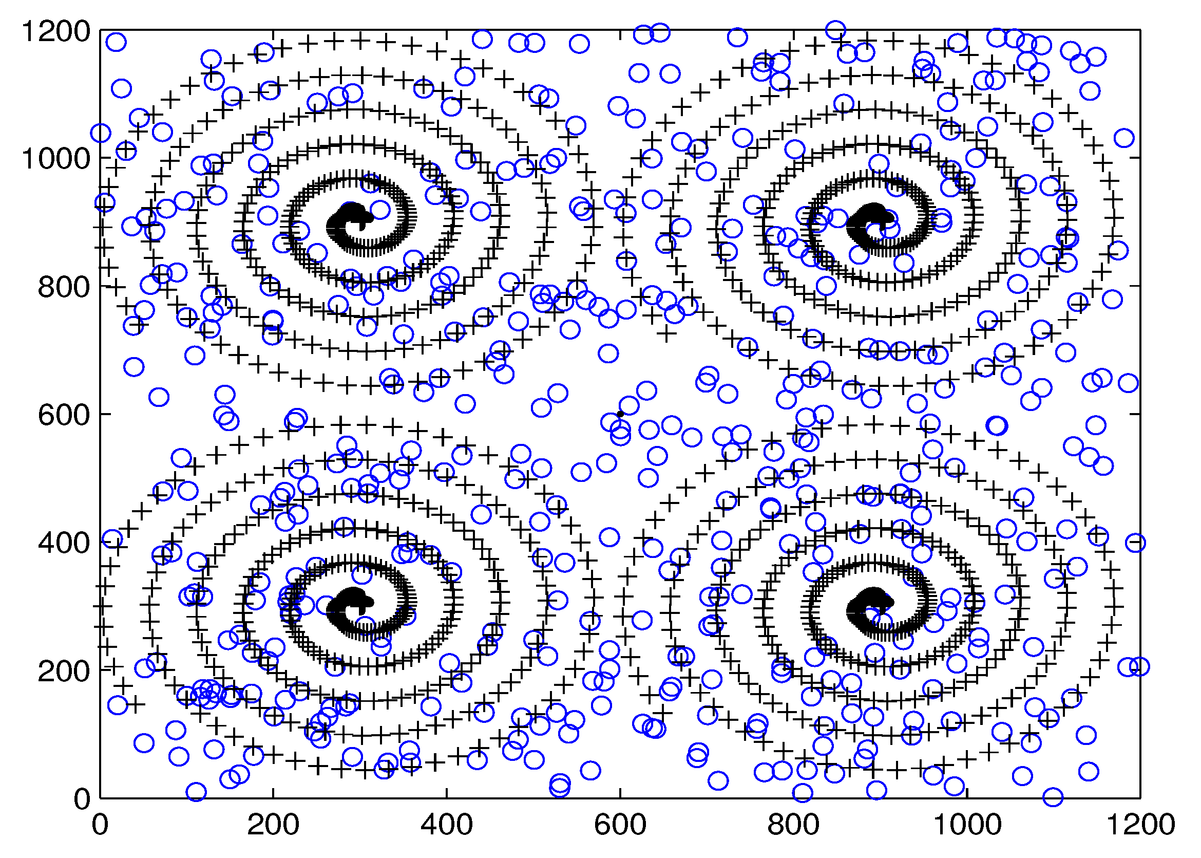
4.2. Multiple Sinks
Sink mobility with a suitable mobility pattern is used to minimize the energy dissipation, but in the case of large-scale networks, the mobile sink takes a longer time to reach the destination, and nodes may lose the critical data due to the constant sensing of the environment. Using multiple sinks in the network can resolve this problem by transmitting the necessary data to the nearest sink. In this paper, we propose multiple sinks based on the spiral mobility pattern for large-scale WSNs. In the proposed model of multiple sinks, we divide the sensing field into four regions and deploy the nodes in a heterogeneous network. All four regions are divided into clusters, and spiral-based controlled mobile sinks move above these four regions for data collection. Each region contains one mobile sink, and this sink is responsible for its specific region. Due to the random deployment of sensor nodes, a few nodes at the center of the network are outside of these four regions. The proposed algorithms are flexible enough to manage these nodes with direct communications with the closest sink. Therefore, the nodes at the central region utilize this property, and these nodes are able to communicate with the nearest sink based on the minimum distance. Figure 3 shows the network diagram of the proposed multiple sinks based on spiral mobility.
5. Proposal of Spiral Mobility Based on Optimized Clustering Routing Protocols
SMOC and M-SMOC are mainly proposed to create energy-efficient clustering routing protocols for optimal data extraction, which improves the reliability and stability with better network lifetime and also produces a higher data delivery ratio with minimum delay. SMOC and M-SMOC enhance cluster formation and choose the best CH based on the residual energy of the node.
5.1. Proposed Model
In the proposed model of SMOC, a single mobile sink with a fixed spiral pattern is moving in the sensor field to collect data from distributed sensor nodes in the network, while in the case of M-SMOC, four mobile sinks are deployed in the sensor field for data extraction from sensor nodes. Initially, when the nodes are deployed, the sink starts cluster formation. All the clusters are formatted in the order of the center, and in this way, the sink can visit them in a spiral pattern. The sink starts visiting from the center of the network and travels to the next point with the valve of X and Y (predefined value) of the sensor field. The sink visits the cluster and waits at the top of the cluster. In the meantime, the CH transmits all the data to the sink and updates the location of the sink to neighbor CHs. Data packets of sensor nodes are neither aggregated nor defragmented unless they reach the sink. After receiving data from the first cluster, the sink moves to the next cluster. Similarly, the sink visits all the clusters in the network, but the waiting time at each cluster is not the same. The sink can stay at any cluster for different amounts of time depending on the number of data packets transmitted by the specific CH, and this variation of time will enhance the data delivery ratio and network lifetime.
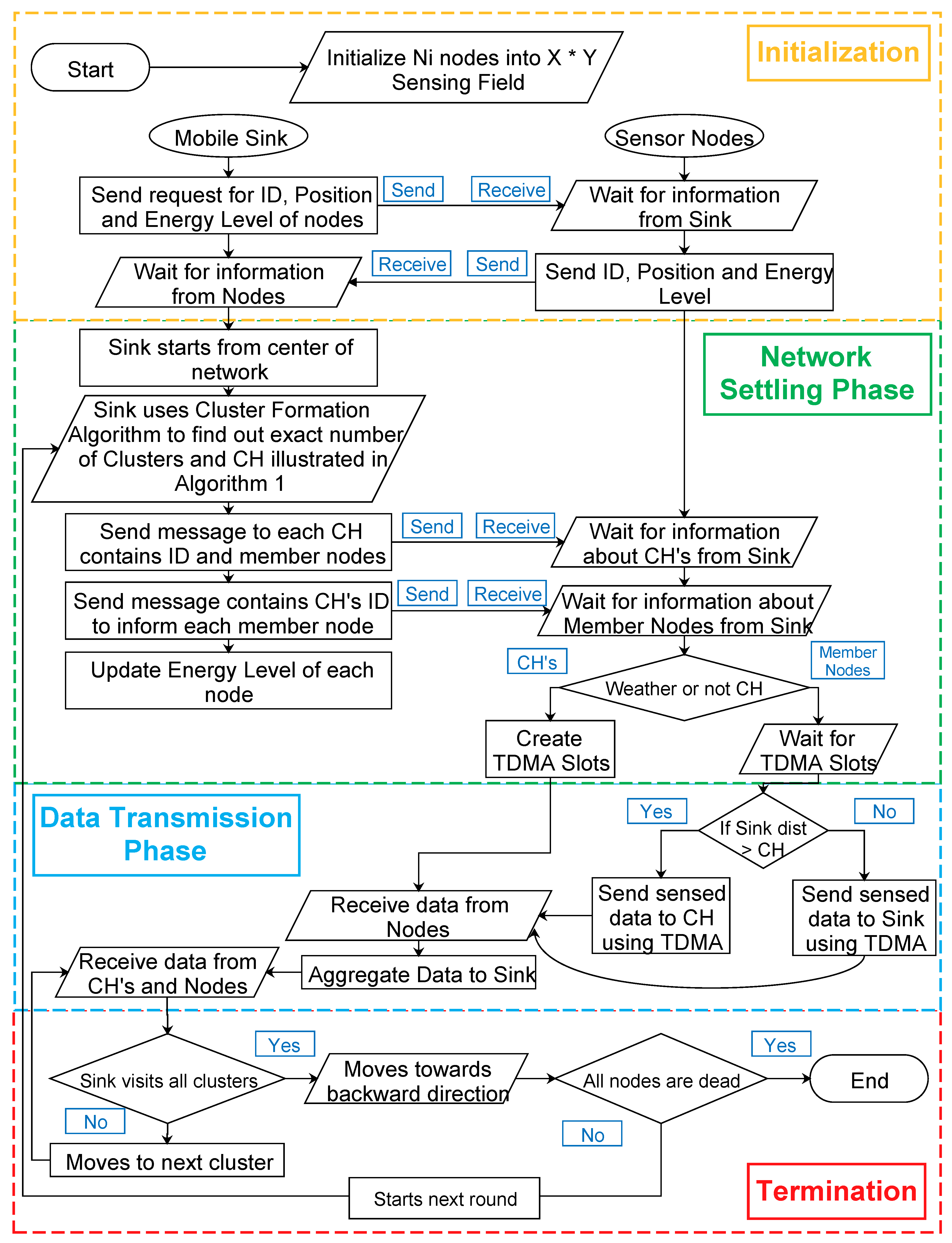
The operation of SMOC and M-SMOC is divided into time-based iterations, and each iteration is subdivided into two phases; network settling phase and data transmission phase. Figure 4 shows the flowchart of the proposed routing protocols.
- Network settling phase: This phase generates a specific number of clusters according to the density of the nodes and the size of the network. The sink enforces advanced cluster-formation and executes it in the network, which removes the redundant clusters and broadcasts the exact number of cluster and CHs in the network. The pseudo-code of the advanced cluster formation is shown in Algorithm 1.
- Data transmission phase: After selecting CHs, the actual communication takes place in the data transmission phase, and the sink starts visiting from cluster-to-cluster, making sure that every node is able to communicate with a specific CH. Meanwhile, the sink receives data from the CHs. After collecting data from all the clusters, the sink starts moving in the backward direction, and reverse mobility takes place. From the last cluster, the sink travels from cluster-to-cluster in the backward direction until it reaches back at the center of the network. After that, the sink starts the second round. We use reverse mobility to avoid extra time taken by the sink to arrive at the starting position for the next round. This feature in spiral mobility will enhance the data delivery ratio, because the sink receives the data from CHs twice in one round. Moreover, the proposed algorithm allows member nodes to transmit sensed data directly to the sink if the distance of the CH is longer than the distance of the sink.
| Algorithm 1: Advanced cluster formation algorithm. |
 |
5.2. Network Settling Phase
The energy dissipation of CHs is higher than member nodes because of the extra processing and communication responsibilities. Therefore, the energy consumption of the CH is the bottleneck to finding the lifetime of the network. As we mentioned earlier, two types of nodes “normal nodes and advanced nodes” are deployed in the network. To find the average number of normal and advanced nodes in one cluster, we calculate respectively:
where are normal nodes and are advanced nodes in the cluster, while A is the area and is the radius of the cluster.
In order to select the CHs between normal and advanced nodes, two types of threshold values are calculated. As per the energy level of nodes, the threshold value of advanced nodes will always be greater than the threshold value of normal nodes. This higher value of the threshold creates more chances for advanced nodes to become CHs. is used to calculate the probability for normal nodes, and is used to calculate the probability for advanced nodes. After the probability calculation of both types of nodes, the threshold values are calculated by the following equations.
After calculating the threshold for normal and advanced nodes, random number will be generated for all nodes . If the threshold value of the specific node is greater than the random number, then this node will be selected as the CH.
Apart from the sink mobility pattern, the path length of the sink in the cluster is , since it should go by the center of the cluster. Moreover, the CH must be within a distance range of r from the sink path. Therefore, the region where CHs are located will be approximately equal to . In order to find the number of CHs and clusters in the network, we calculate respectively:
and:
5.3. Data Transmission Phase
In the transmission phase of SMOC and M-SMOC, communication between the nodes, CH and sink takes place. Nodes transmit their sensed data to the specific CH using their assigned TDMA slots; these CHs wait for the mobile sink until the sink reaches a specific cluster, and the CH forwards these data to the mobile sink.
The CH dissipates two-times the energy in one round. First, it needs to receive - data from the member nodes. The dissipated energy of the CH while receiving data can be calculated as:
Second, it has to transmit these data to the sink, according to the network topology distance between CHs and the sink being a random variable between . Thus, the energy needed for transmission of - data to the sink is:
where p is the path loss exponent. By replacing the in Equation (1), we can calculate the total energy consumption of CH in one round.
CHs utilize a small amount of energy to transmit the data of nodes to the sink, because the sink is moving in a spiral pattern, and when it arrives at the cluster, it will be near the CHs, so the transmission cost from the CHs to the sink is minimized; thus, the bottleneck issue of the network is the working time of the CHs. The network lifetime in terms of the round can be calculated as:
To save the energy dissipation in long-range data transmission, the proposed routing techniques allow member nodes to transmit sensed data directly to the sink if the distance between the member nodes to the CH is greater than the distance between the member nodes to the sink.
Algorithm 2 shows the communication mechanism between member nodes and the mobile sink.
| Algorithm 2: Data transmission between the member node and the mobile sink. |
 |
6. Experiments and Simulation Results
This section presents the performance evaluation of the proposed routing techniques SMOC and M-SMOC, and the results are compared with LEACH [15], HEED [16] and EECS [17] for the comparison with the static sink, and for the comparison with the mobile sink, we compared the results with the ZEEP [18] and TARS [19] routing protocols.
6.1. Experimental Methodology
To evaluate the performance of SMOC and M-SMOC, we have done simulations in the MATLAB v9.2 environment. This is similar to other environments such as OMNET ++ and NS-2 with the difference that MATLAB provides a feature architecture and allows rapid simulations by combining multiple components. To provide a better presentation of the experimental results, we use OriginLab for deep analysis. Multiple scenarios and various parameters are considered to evaluate the performance.
6.2. Simulation Parameters
The proposed protocols are executed in different network dimensions with different heterogeneity levels. First, we validate the proposed analysis in a standard network model for SMOC and M-SMOC, then compare it with different parameters. To remove the error, each simulation runs at least five times, and the average is considered as the final result. The detailed standard network simulation parameters are given in Table 1.
6.3. Mobility vs. Static Sink
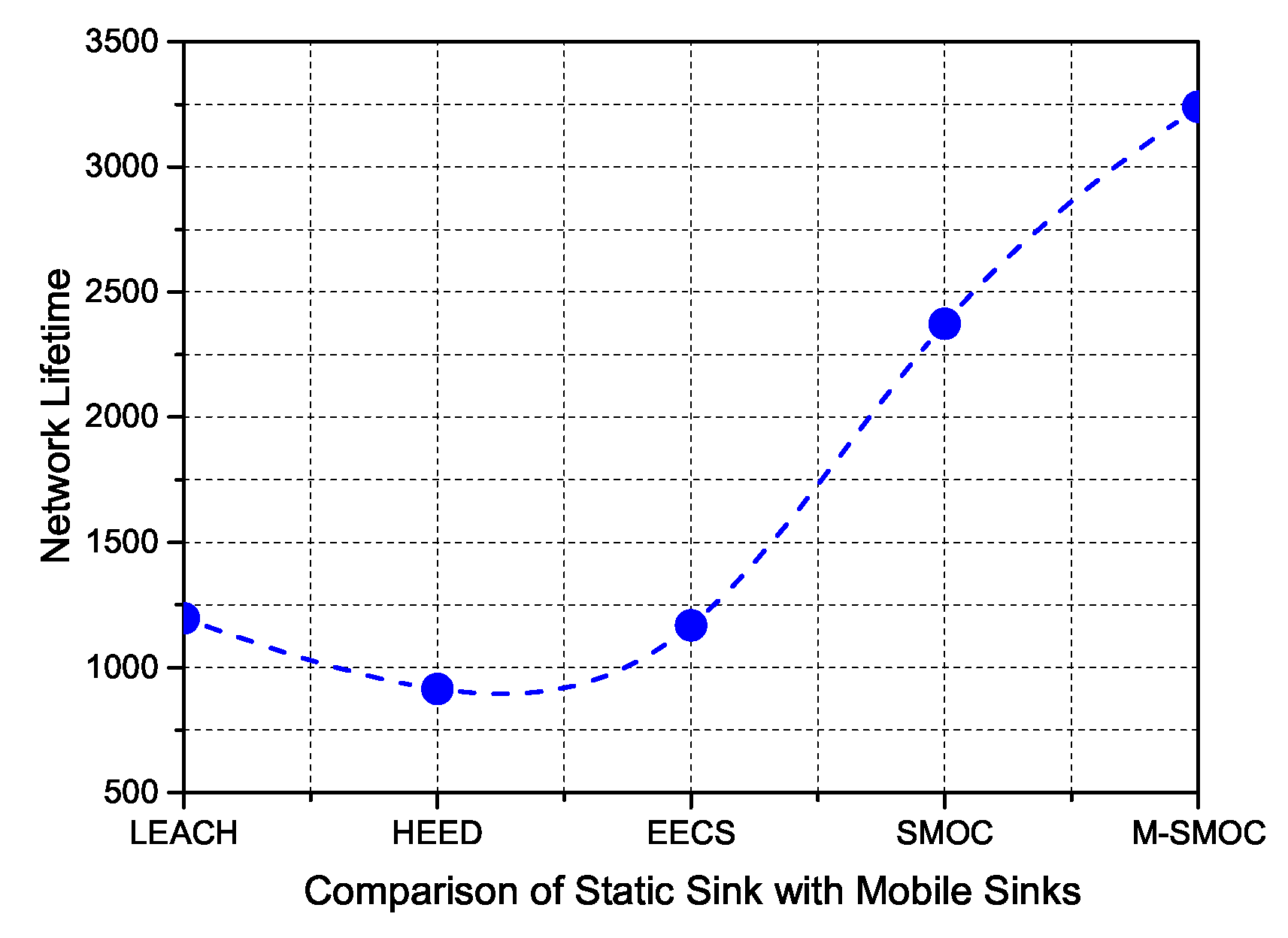
The proposed routing protocols based on the controlled spiral mobility pattern are compared with the existing routing protocols, which use the static sink LEACH, HEED and EECS routing protocols. We took the network parameters the same as mentioned in the previous routing protocols. The network consists of 100 nodes with initial energy J deployed randomly in the 100 m × 100 m sensing field. The size of the data packet is 2048 bits with the transmit circuitry 50 nJ/bit, and the static sink is located in the center of the network. From the obtained results, it is seen that the proposed protocols produce better network lifetime as compared to existing routing protocols based on the static sink. Table 2 shows the performance comparison of the proposed mobile sink routing protocols with existing static sink routing protocols.
The proposed SMOC routing protocol extends the network lifetime compared with LEACH, HEED and EECS by 1176, 1459 and 1205 rounds and extends the network stability by 674, 980 and 896 rounds, respectively. In the comparison of the multiple mobile sinks with the single static sink, the proposed M-SMOC routing protocol performed more efficiently and extended the network lifetime by 2197, 2480 and 2226 rounds; similarly, the proposed M-SMOC extends the network stability by 1379, 1685 and 1601 rounds, respectively. The major reason for this improvement is efficient cluster formation along with inclusion of four sinks instead of a single sink. Multiple sinks are responsible for collecting information from their nearby regions, and in this way, less energy dissipation is observed. Moreover, the proposed spiral mobility also reduces the instability period as compared to previous routing protocols, because of the efficient CH selection.
In Figure 5, the graph shows the comparison of the network lifetime of the proposed routing protocols with the existing state-of-the-art static sink routing protocols. Among the five algorithms, the network lifetimes of the SMOC and M-SMOC algorithms are better. It can be observed that the proposed algorithms have the maximum advantage of mobile sinks. In other words, SMOC achieves 95% better performance over existing routing protocols, while M-SMOC achieves 140% better network lifetime.
6.4. Spiral Mobility vs. Random and Grid Mobility
In this section, we compare the proposed spiral mobility pattern with the random and grid mobility pattern. In order to provide a better comparison, we compare the results with existing routing protocols ZEEP and TARS, which contain the random and the grid mobility pattern, respectively.
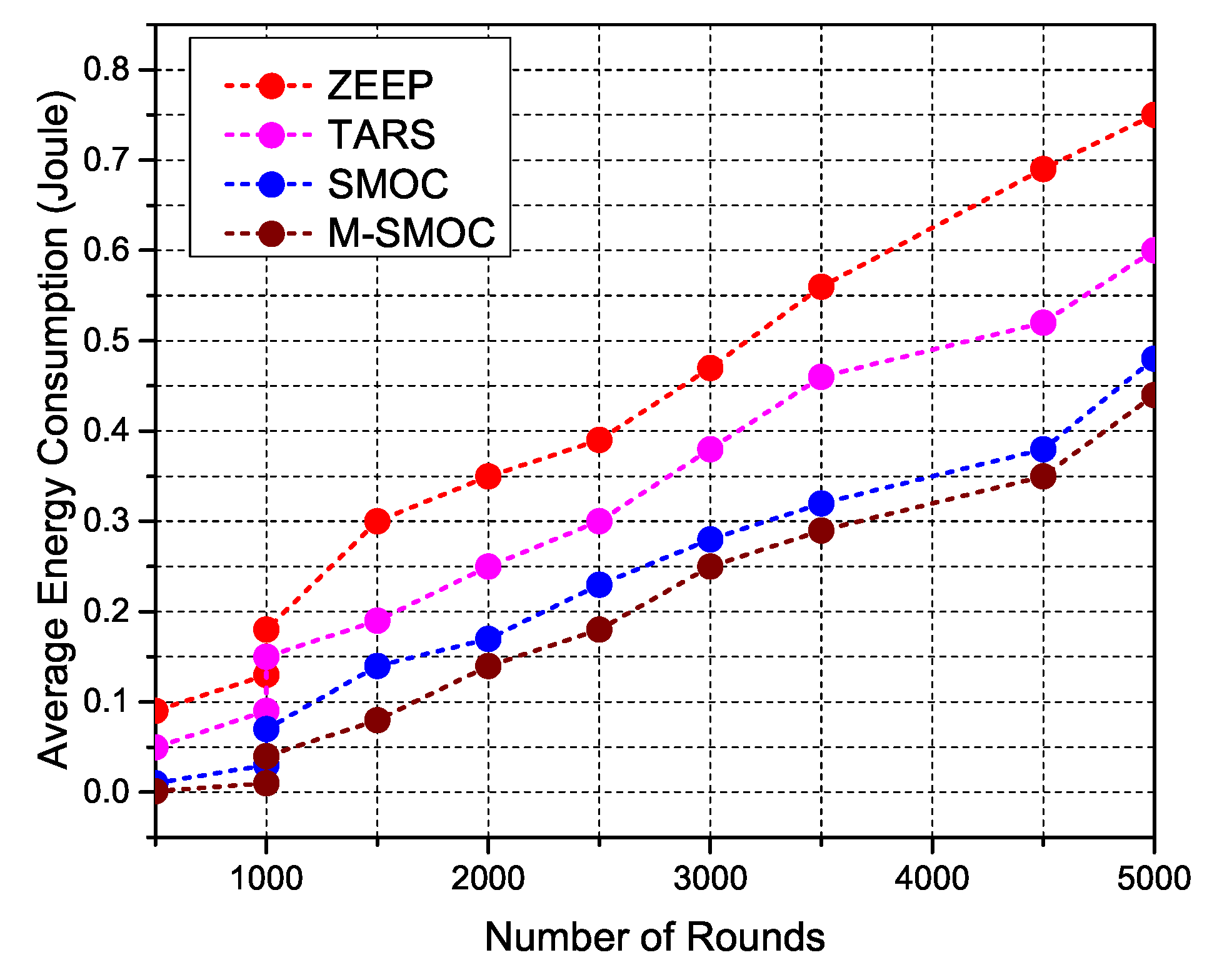
Figure 6 shows the comparison of the average energy consumption with respect to the network lifetime for all four algorithms, ZEEP, TARS, SMOC and M-SMOC. From Figure 6, it is noticed that the mobility pattern in the proposed algorithm gradually extends the network lifetime as compared to the random and grid mobility. The obtained result clearly shows that the proposed algorithm greedily dissipates energy, and this is because spiral mobility covers the whole network area, which provides transmission between sensor nodes and the mobile sink at a shorter distance. It can be seen clearly that the SMOC and M-SMOC algorithms achieve higher performance with better network lifetime. This average energy consumption is linearly and inversely proportional to the network lifetime, with the M-SMOC algorithm achieving quite better performance due to the four mobile sinks in the network.
Figure 7 shows the graph of the energy consumption in the ZEEP, TARS, SMOC and M-SMOC approaches, respectively. The proposed techniques select more CHs in non-hot-spot areas and balances the energy dissipation throughout the network; this is because the proposed routing protocols completely used the residual energy of sensor nodes in order to select CHs and reduced the network distortion.
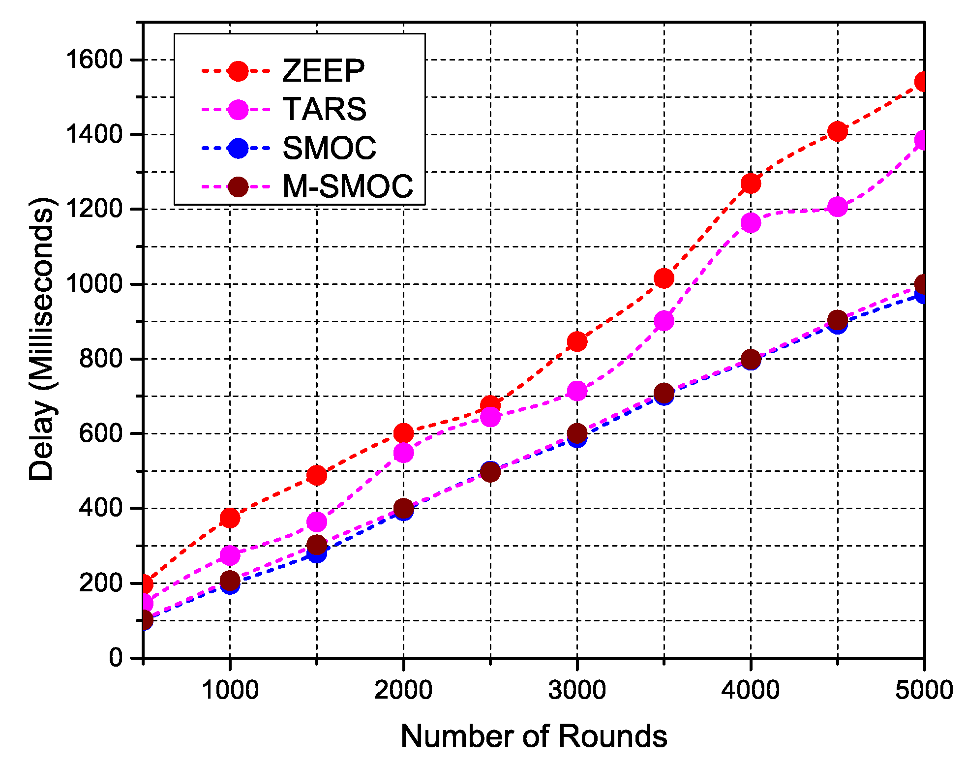
Figure 8 shows the comparison of end-to-end packet delay between ZEEP, TARS, SMOC and M-SMOC. It is observed that the average delay per round of the proposed protocols is 8.64 and 8.24 ms respectively, because the proposed mobility pattern covers the whole region of the sensor field and collects the data from the sensor nodes at a shorter distant. It is clearly seen that the delay of SMOC is higher than M-SMOC due to the multiple sinks in the sensor field of the M-SMOC approach, where mobile sinks are closer to the sensor nodes.
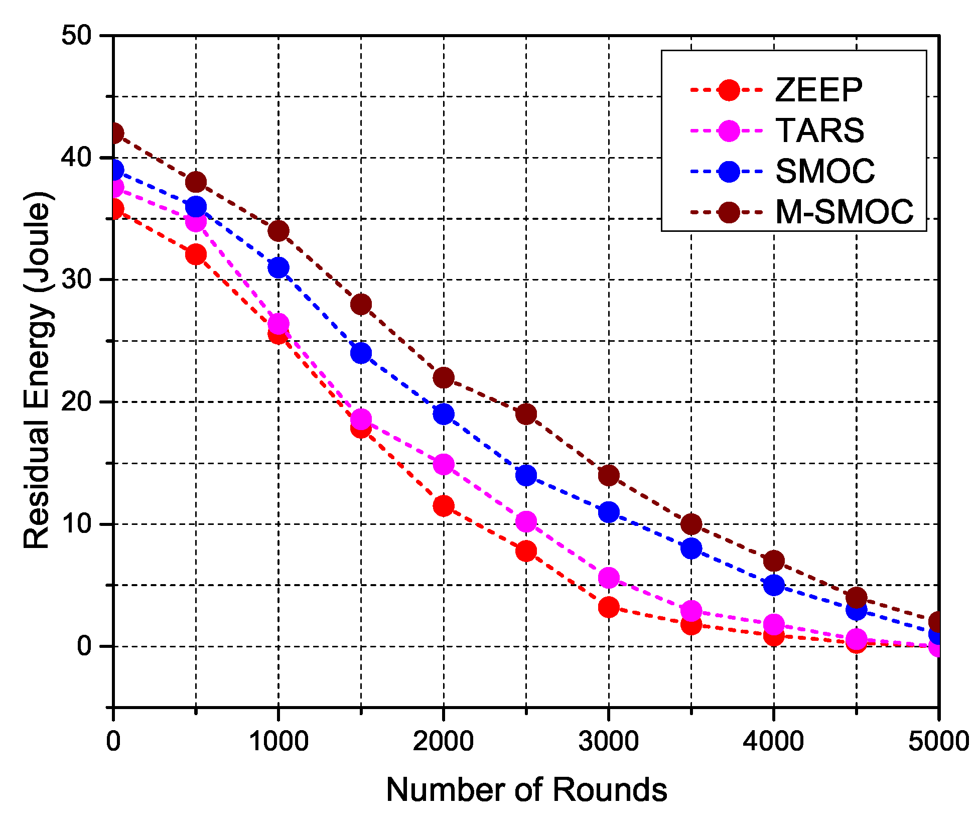
Figure 9 shows the residual energy of sensor nodes in the network with respect to every passing round. It is noticed that the proposed routing protocols SMOC and M-SMOC extend the network lifetime by dividing the network load among all the sensor nodes that are closer to the mobile sink, which helps them to increase network stability and results in better network lifetime. This proves that the proposed spiral mobility pattern is more energy efficient than other random and grid mobility patterns, because it allows the sensor nodes to work with full functionality for a longer period of time. This means that the proposed algorithm successfully eliminates the energy hole problem from the network and provides better performance in terms of network lifetime and network stability.
When a sensor node transmits its data to the sink, it is supposed that all the data packets are transmitted and received by the sink successfully without any loss. However, in reality, due to reflection, noise, attenuation and interference, some data packets of sensor nodes are dropped. We use the uniform random distribution model to calculate the packet drop ratio [36]. The probability of packet drop varies because of changes in the distance of the sink from the node, which is mentioned in Equation (15). If the probability is smaller than , then the packet will be dropped; otherwise, it will be successfully delivered.
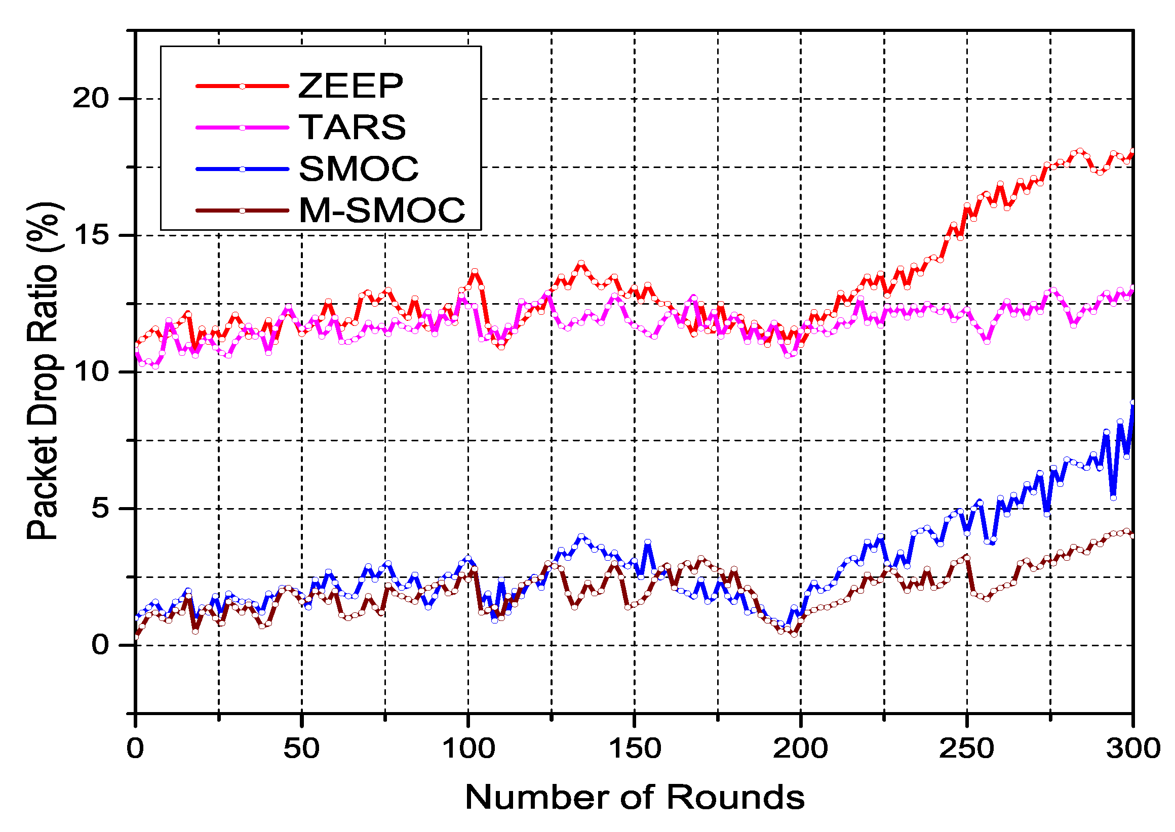
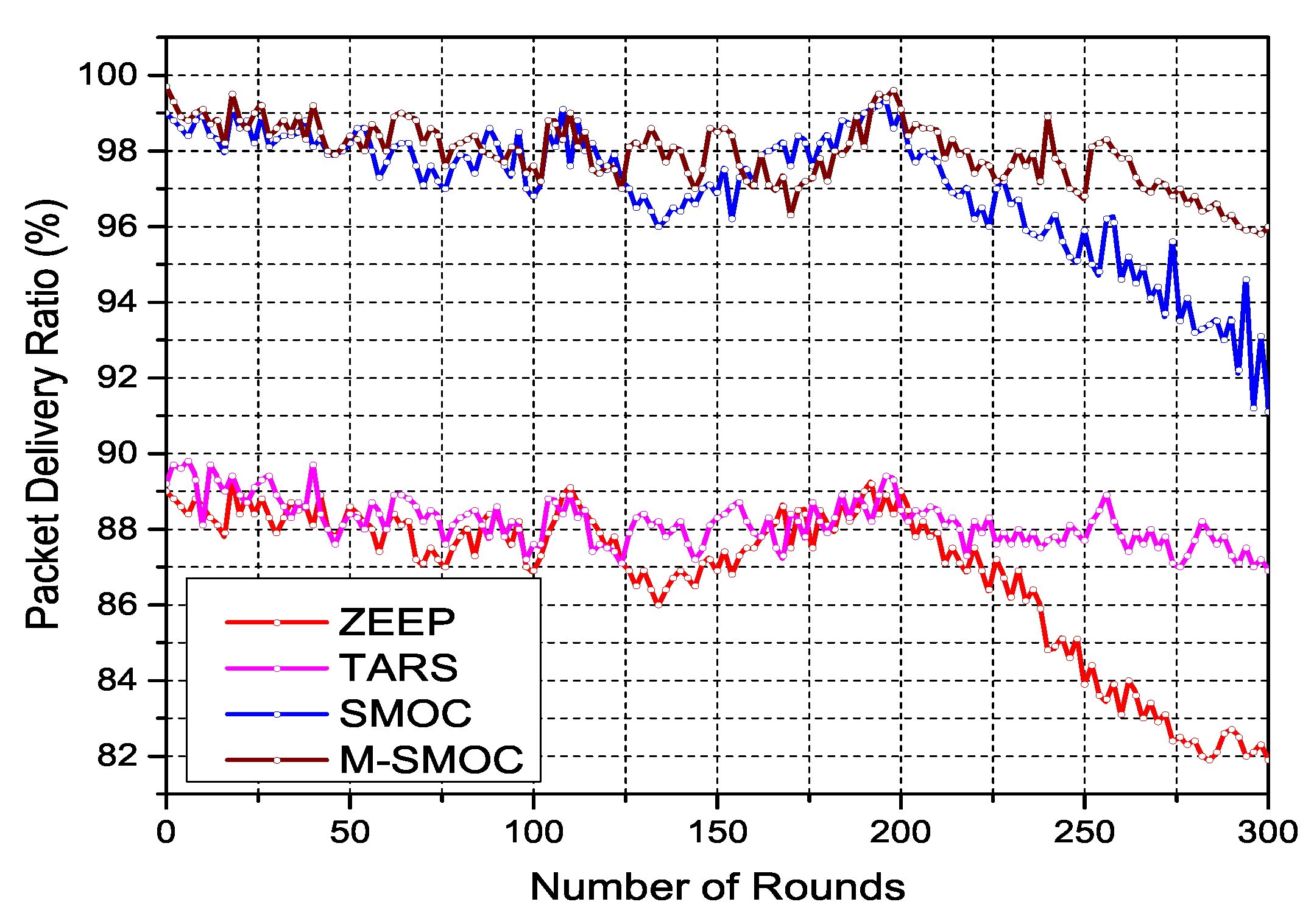
Figure 10 and Figure 11 show the packet drop and delivery ratio, respectively. The obtained results show that the proposed M-SMOC protocol attains a high packet delivery ratio and a low packet drop ratio, and it can be seen that the packet drop ratio in SMOC is a bit higher than the M-SMOC protocol and that M-SMOC delivers more data packets because of the extra mobility using multiple sinks.
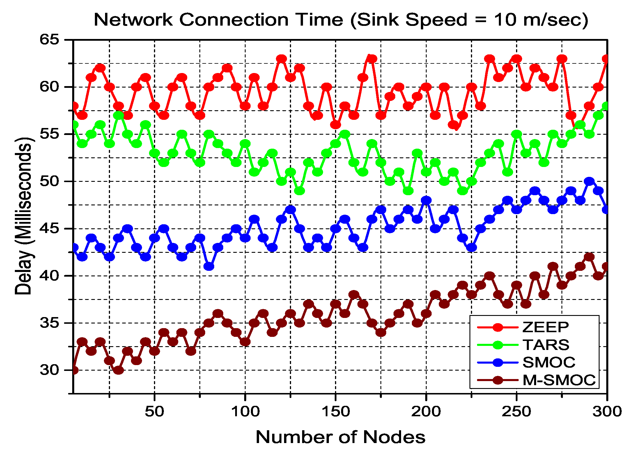
Efficiency in data delivery is directly proportional to the network connection time, as the nodes know the location of the mobile sink more precisely, and they select more efficient routes for data aggregation. Constituting the fundamental setup of the network, it is the approximation of the elapsed time during which a mobile sink changes a significant position that is noted by the nearby nodes. In the network connection time, the node performs better in data aggregation if the node updates the location of the mobile sink faster. Connection times of the proposed routing protocols SMOC and M-SMOC are shown in Figure 12 with the comparison of ZEEP and TARS.
As per the simulation parameters, our proposed routing protocols share the location of the mobile sink and intelligently aggregate the sensed data. In the case of M-SMOC, all the CHs use a subset of route readjustment in the header and greedily share the updated location of the mobile sink with each other. This readjustment header leads the M-SMOC to a faster connection of nodes for the updated location of the mobile sink. Moreover, it can be seen that the proposed M-SMOC protocol achieved a better network connection time because of the multiple sinks in the network.
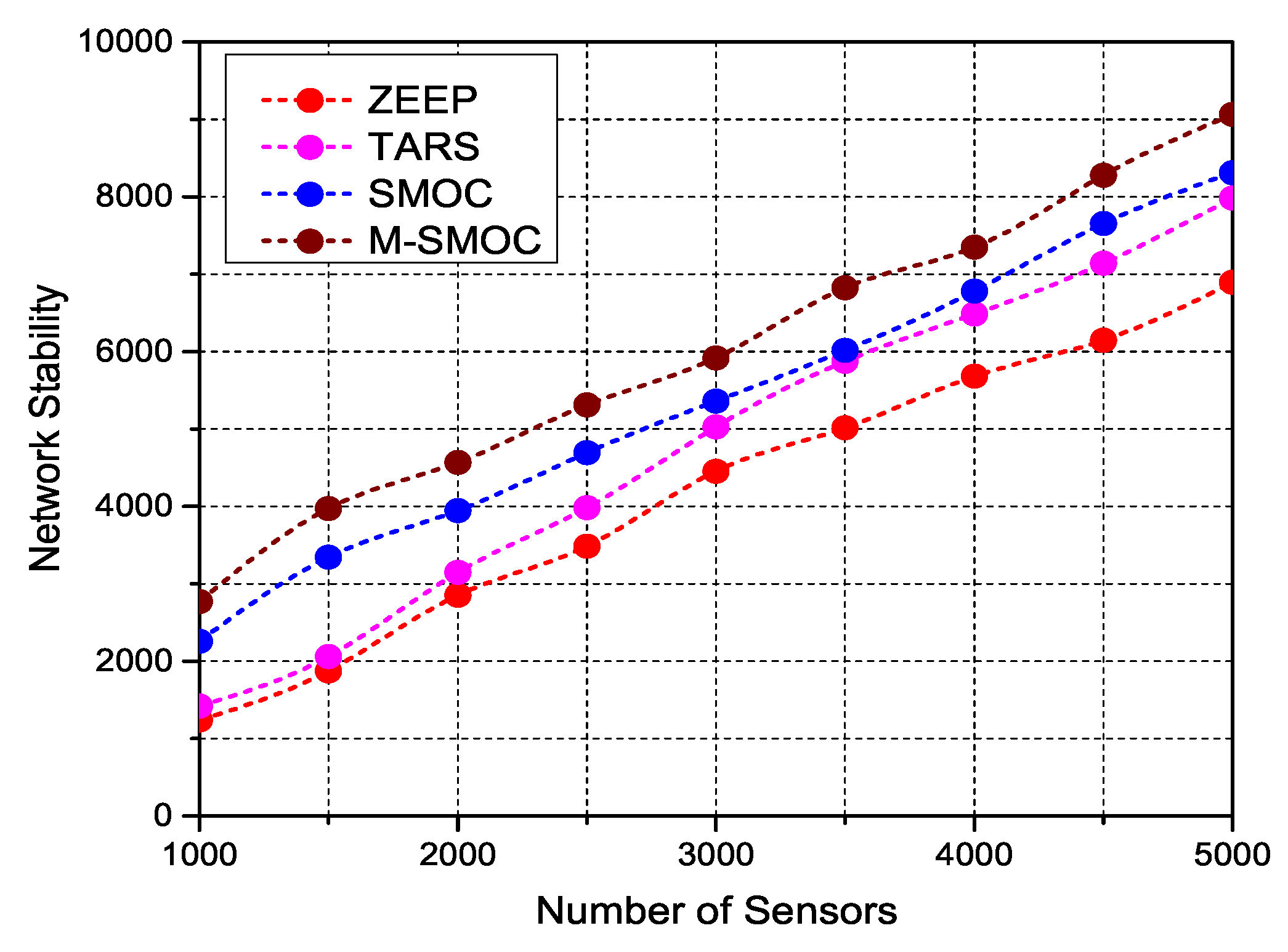
As shown in Figure 13, with the increase in the number of sensor nodes in the network, the network stability achieved by any of the four algorithms also increases.
Both the SMOC and M-SMOC algorithms perform better in the comparison of the ZEEP and TARS routing algorithms. This is due to the fact that the proposed spiral mobility pattern covers the whole network region and works better with the involvement of a higher number of sensor nodes. We pay attention to the number of sensors involved, because a higher number of sensors share the total energy consumption and the network response time. If the number of sensors in the network is higher, then these sensors require minimum energy to transmit data, but this will be at the cost of the shorter response time. With the deployment of a higher number of sensor nodes, the network stability of SMOC algorithm is low in comparison with M-SMOC, which is due to the single mobile sink in the SMOC algorithm; whereas the M-SMOC algorithm achieves higher network stability because multiple sinks are moving over CHs. This is the only reason why the network stability of the SMOC algorithm is comparatively shorter. Moreover, with the increase of sensors scattered in the field, the network lifetime of the SMOC and M-SMOC algorithms also improves.
In Figure 14, we compare the network lifetime between the proposed algorithms with the impact of different heterogeneity levels in the various sizes of networks. In Figure 14, the considered network dimensions are 100 m × 100 m, 150 m × 150 m, 200 m × 200 m, 250 m × 250 m and 300 m × 300 m, and the heterogeneity levels are 0.5 J, 1.0 J, 1.5 J, 2.0 J and 2.5 J, respectively. The number of sensors in the defined networks is 100, 200, 250, 350 and 500, respectively. As shown in Figure 14, with the increase of the network dimensions, even if a proportional number of sensor nodes in the network is scattered, the network lifetime is gradually increased in both algorithms. Furthermore, the M-SMOC algorithm produces better results in large-scale networks than the SMOC algorithm, because of the extra mobile sinks in the network.
7. Performance Evaluation and Results Discussion
In this paper, we deeply studied the literature and proposed two routing protocols based on controlled mobility with a spiral pattern. We compare the results of the proposed routing protocols with the static sink and mobile sink-based routing protocols, respectively, in Section 6. LEACH, HEED and EECS are the well-known existing routing protocols based on the static sink, while ZEEP and TARS are based on the mobile sink with the random and the grid mobility pattern, respectively. However, as proven in Section 6, these existing schemes are not very efficient due to their limited characteristics. Table 3 shows the comparison of the characteristics of the proposed schemes with the existing routing protocols.
8. Conclusions and Future Work
In this paper, we propose two mobility-based clustering techniques called Spiral Mobility based on Optimized Clustering (SMOC) and Multiple sink-based SMOC (M-SMOC) for large-scale WSNs. The proposed routing protocols adapt the advanced CH selection algorithm, which selects the optimum number of CHs and results in the minimization of the dissipated energy in data transmission. In order to assess the characteristics, we investigate the spiral mobility pattern in the proposed models under fair terms of optimal network conditions (i.e., network connection time and total energy consumption). The proposed models develop a novel optimized clustering framework that optimizes the network connection time and greedily consumes the overall energy of the network. By using the developed framework, we explore the design space of mobility-based WSNs (i.e., network dimensions, number of involved sensors, initial energy, size of data packet) with the trajectory of the spiral pattern. The proposed models achieve a better network lifetime and stability period by eliminating the energy hole problem. The simulation results of SMOC and M-SMOC are compared with existing state-of-the-art static sink routing protocols, namely LEACH, HEED and EECS, and mobile sink routing protocols, namely ZEEP and TARS. It is realized that the unique spiral mobility pattern of the mobile sink is more reliable and more energy efficient than the static sink. The proposed controlled mobility-based spiral pattern outperforms in terms of network lifetime, network stability, energy consumption, packet drops and the packet delivery ratio. Moreover, the proposed spiral mobility eliminates the hot-spot problem, because the control mobility pattern covers the whole network area, which helps with packets’ delivery and also increases the robustness of the network.
To further improve the network lifetime and stability period, multi-hop SMOC and M-SMOC can be implemented in the NS-3 simulation environment, which is considered as a future work of this research.
Acknowledgments
This research is undertake and funded by the School of Computer Science and Technology of Dalian University of Technology.
Author Contributions
Muhammad Asad, Master’s degree student, under the supervision of Yao Nianmin and Muhammad Aslam, conducted this research work. Muhammad Asad and Yao Nianmin conceived of and designed the proposed model of the SMOC and M-SMOC routing protocols. Yao Nianmin finalized the theoretical framework, while Muhammad Asad performed the simulation experiments. Muhammad Aslam validated the performance outcomes by comparing the results with existing routing protocols and performed critical revisions. All authors have read and approved the final manuscript.
Conflicts of Interest
The authors declare no conflict of interest regarding the publication of this research article.
References
- Gu, L.; Jia, D.; Vicaire, P.; Yan, T.; Luo, L.; Tirumala, A.; Cao, Q.; He, T.; Stankovic, J.A.; Abdelzaher, T.; et al. Lightweight detection and classification for wireless sensor networks in realistic environments. In Proceedings of the 3rd international conference on Embedded networked sensor systems, San Diego, CA, USA, 2–4 November 2005; pp. 205–217. [Google Scholar]
- Paradiso, J.A.; Starner, T. Energy scavenging for mobile and wireless electronics. IEEE Pervasive Comput. 2005, 4, 18–27. [Google Scholar] [CrossRef]
- Gubbi, J.; Buyya, R.; Marusic, S.; Palaniswami, M. Internet of Things (IoT): A vision, architectural elements, and future directions. Future Gener. Comput. Syst. 2013, 29, 1645–1660. [Google Scholar] [CrossRef]
- Rault, T.; Bouabdallah, A.; Challal, Y. Energy efficiency in wireless sensor networks: A top-down survey. Comput. Netw. 2014, 67, 104–122. [Google Scholar] [CrossRef]
- Liu, X. A survey on clustering routing protocols in wireless sensor networks. Sensors 2012, 12, 11113–11153. [Google Scholar] [CrossRef] [PubMed]
- Singh, S.K.; Singh, M.P.; Singh, D.K. A survey of energy-efficient hierarchical cluster-based routing in wireless sensor networks. Int. J. Adv. Netw. Appl. 2010, 2, 570–580. [Google Scholar]
- Swati, A.J.; Priyanka, R. Wireless sensor network (WSN): Architectural design issues and challenges. Int. J. Comput. Sci. Eng. 2010, 2, 3089–3094. [Google Scholar]
- Li, J.; Mohapatra, P. Analytical modeling and mitigation techniques for the energy hole problem in sensor networks. Pervasive Mob. Comput. 2007, 3, 233–254. [Google Scholar] [CrossRef]
- Oyman, E.I.; Ersoy, C. Multiple sink network design problem in large scale wireless sensor networks. In Proceedings of the 2004 IEEE International Conference on Communications, Paris, France, 20–24 June 2004; Volume 6, pp. 3663–3667. [Google Scholar]
- Gu, Y.; Ren, F.; Ji, Y.; Li, J. The evolution of sink mobility management in wireless sensor networks: A survey. IEEE Commun. Surv. Tutor. 2016, 18, 507–524. [Google Scholar] [CrossRef]
- Wu, X.; Chen, G.; Das, S.K. Avoiding energy holes in wireless sensor networks with nonuniform node distribution. IEEE Trans. Parallel Distrib. Syst. 2008, 19, 710–720. [Google Scholar]
- Cayirpunar, O.; Tavli, B.; Kadioglu-Urtis, E.; Uludag, S. Optimal Mobility Patterns of Multiple Base Stations for Wireless Sensor Network Lifetime Maximization. IEEE Sens. J. 2017, 17, 7177–7188. [Google Scholar] [CrossRef]
- Basagni, S.; Carosi, A.; Petrioli, C. Controlled vs. uncontrolled mobility in wireless sensor networks: Some performance insights. In Proceedings of the 2007 IEEE 66th Vehicular Technology Conference, VTC-2007 Fall, Baltimore, MD, USA, 30 September–3 October 2007; pp. 269–273. [Google Scholar]
- Sabor, N.; Sasaki, S.; Abo-Zahhad, M.; Ahmed, S.M. A Comprehensive Survey on Hierarchical-Based Routing Protocols for Mobile Wireless Sensor Networks: Review, Taxonomy, and Future Directions. Wirel. Commun. Mob. Comput. 2017, 2017, 2818542. [Google Scholar] [CrossRef]
- Heinzelman, W.R.; Chandrakasan, A.; Balakrishnan, H. Energy-efficient communication protocol for wireless microsensor networks. In Proceedings of the 33rd Annual Hawaii International Conference on System Sciences, Maui, HI, USA, 7 January 2000; p. 10. [Google Scholar]
- Younis, O.; Fahmy, S. HEED: A hybrid, energy-efficient, distributed clustering approach for ad hoc sensor networks. IEEE Trans. Mob. Comput. 2004, 3, 366–379. [Google Scholar] [CrossRef]
- Ye, M.; Li, C.; Chen, G.; Wu, J. EECS: An energy efficient clustering scheme in wireless sensor networks. In Proceedings of the 24th IEEE International Performance, Computing, and Communications Conference, IPCCC 2005, Phoenix, AZ, USA, 7–9 April 2005; pp. 535–540. [Google Scholar]
- Srivastava, J.R.; Sudarshan, T.S. ZEEP: Zone based energy efficient routing protocol for mobile sensor networks. In Proceedings of the 2013 International Conference on Advances in Computing, Communications and Informatics (ICACCI), Mysore, India, 22–25 August 2013; pp. 990–996. [Google Scholar]
- Chi, Y.P.; Chang, H.P. TARS: An energy-efficient routing scheme for wireless sensor networks with mobile sinks and targets. In Proceedings of the 2012 IEEE 26th International Conference on Advanced Information Networking and Applications (AINA), Fukuoka, Japan, 26–29 March 2012; pp. 128–135. [Google Scholar]
- Natalizio, E.; Loscrí, V. Controlled mobility in mobile sensor networks: Advantages, issues and challenges. Telecommun. Syst. 2013, 52, 2411–2418. [Google Scholar] [CrossRef]
- Vecchio, M.; Viana, A.C.; Ziviani, A.; Friedman, R. DEEP: Density-based proactive data dissemination protocol for wireless sensor networks with uncontrolled sink mobility. Comput. Commun. 2010, 33, 929–939. [Google Scholar] [CrossRef]
- Kim, J.W.; In, J.S.; Hur, K.; Kim, J.W.; Eom, D.S. An intelligent agent-based routing structure for mobile sinks in WSNs. IEEE Trans. Consum. Electron. 2010, 56. [Google Scholar] [CrossRef]
- Nazir, B.; Hasbullah, H. Mobile sink based routing protocol (MSRP) for prolonging network lifetime in clustered wireless sensor network. In Proceedings of the 2010 International Conference on Computer applications and industrial electronics (ICCAIE), Kuala Lumpur, Malaysia, 5–8 December 2010. [Google Scholar]
- Oh, S.; Lee, E.; Park, S.; Jung, J.; Kim, S.H. Communication scheme to support sink mobility in multi-hop clustered wireless sensor networks. In Proceedings of the 2010 24th IEEE International Conference on Advanced Information Networking and Applications (AINA), Perth, Australia, 20–23 April 2010; pp. 866–872. [Google Scholar]
- Lin, C.J.; Chou, P.L.; Chou, C.F. HCDD: Hierarchical cluster-based data dissemination in wireless sensor networks with mobile sink. In Proceedings of the 2006 International Conference on Wireless Communications and Mobile Computing, Vancouver, BC, Canada, 3–6 July 2006; pp. 1189–1194. [Google Scholar]
- Pradeepa, K.; Anne, W.R.; Duraisamy, S. Improved sensor network lifetime using multiple mobile sinks: A new predetermined trajectory. In Proceedings of the 2010 International Conference on Computing Communication and Networking Technologies (ICCCNT), Karur, India, 29–31 July 2010; pp. 1–6. [Google Scholar]
- Nguyen, N.T.; Liu, B.H.; Pham, V.T.; Luo, Y.S. On maximizing the lifetime for data aggregation in wireless sensor networks using virtual data aggregation trees. Comput. Netw. 2016, 105, 99–110. [Google Scholar] [CrossRef]
- Liu, B.H.; Pham, V.T.; Nguyen, N.T. An efficient algorithm of constructing virtual backbone scheduling for maximizing the lifetime of dual-radio wireless sensor networks. Int. J. Distrib. Sens. Netw. 2015, 11, 475159. [Google Scholar] [CrossRef]
- Yu, S.; Zhang, B.; Li, C.; Mouftah, H. Routing protocols for wireless sensor networks with mobile sinks: A survey. IEEE Commun. Mag. 2014, 52, 150–157. [Google Scholar] [CrossRef]
- Mehrabi, A.; Kim, K. General framework for network throughput maximization in sink-based energy harvesting wireless sensor networks. IEEE Trans. Mob. Comput. 2017, 16, 1881–1896. [Google Scholar] [CrossRef]
- Sundararaman, B.; Buy, U.; Kshemkalyani, A.D. Clock synchronization for wireless sensor networks: A survey. Ad Hoc Netw. 2005, 3, 281–323. [Google Scholar] [CrossRef]
- Wang, Q.; Yang, W. Energy consumption model for power management in wireless sensor networks. In Proceedings of the 4th Annual IEEE Communications Society Conference on Sensor, Mesh and Ad Hoc Communications and Networks, SECON’07, San Diego, CA, USA, 18–21 June 2007; pp. 142–151. [Google Scholar]
- Ahmed, G.; Zou, J.; Fareed, M.M.; Zeeshan, M. Sleep-awake energy efficient distributed clustering algorithm for wireless sensor networks. Comput. Electr. Eng. 2015, 56, 385–398. [Google Scholar] [CrossRef]
- Bicakci, K.; Gultekin, H.; Tavli, B. The impact of one-time energy costs on network lifetime in wireless sensor networks. IEEE Commun. Lett. 2009, 13. [Google Scholar] [CrossRef]
- Martinez-Sala, A.; Molina-Garcia-Pardo, J.M.; Egea-Ldpez, E.; Vales-Alonso, J.; Juan-Llacer, L.; Garcia-Haro, J. An accurate radio channel model for wireless sensor networks simulation. J. Commun. Netw. 2005, 7, 401–407. [Google Scholar] [CrossRef]
- Zhou, Q.; Cao, X.; Chen, S.; Lin, G. A solution to error and loss in wireless network transfer. In Proceedings of the International Conference on Wireless Networks and Information Systems, WNIS’09, Shanghai, China, 28–29 December 2009; pp. 312–315. [Google Scholar]
Figure 1.
Radio model used in the proposed routing protocols.

Figure 2.
Network design executing spiral mobility.

Figure 3.
Network design of spiral mobility executed with multiple sinks for large-scale WSNs.

Figure 4.
Flowchart of the proposed Spiral Mobility based on Optimized Clustering (SMOC) and Multiple sink-based SMOC (M-SMOC) routing protocols.
Figure 4.
Flowchart of the proposed Spiral Mobility based on Optimized Clustering (SMOC) and Multiple sink-based SMOC (M-SMOC) routing protocols.

Figure 5.
Comparison of the proposed mobile sink with existing static sink over network lifetime

Figure 6.
Comparison of the network lifetime in terms of energy consumption.

Figure 7.
Comparison of the average energy consumption with respect to the number of rounds.

Figure 8.
Comparison of the end-to-end delay with respect to the number of rounds.

Figure 9.
Comparison of the residual energy of sensor nodes with respect to the number of rounds.

Figure 10.
Performance comparison of the packet drop ratio.

Figure 11.
Performance comparison of the packet delivery ratio.

Figure 12.
Comparison of the network connection time with various sizes of the network.

Figure 13.
Comparison of the network stability with various numbers of sensors in the network.

Figure 14.
Comparison of the network lifetime of the proposed protocols with various sizes of networks.
Figure 14.
Comparison of the network lifetime of the proposed protocols with various sizes of networks.


Table 1.
Characterization of simulation parameters.
| Parameters | Values |
|---|---|
| Sensor Nodes | 100 |
| Network Dimensions | 100 m × 100 m |
| Initial Energy | 0.5 J |
| Required CHs Per Round | 10% |
| Transmission Energy Dissipation | 50 pJ/bit |
| Data Packet Size | 2048 bit |
| Transmission Energy | 50 nJ/bit |
| Receiver Energy | 50 nJ/biT |
| Amplifier Transmission Energy Dissipation | 100 pJ/bit/m |
Table 2.
Performance comparison of SMOC and M-SMOC with existing static sink routing protocols.
| Sink Location | Routing Protocol | Number of Rounds | |
|---|---|---|---|
| Network Lifetime | Network Stability | ||
| Static-Sink | LEACH | 1197 | 893 |
| HEED | 914 | 587 | |
| EECS | 1168 | 671 | |
| Mobile Sink | SMOC | 2373 | 1567 |
| Multiple Mobile Sink | M-SMOC | 3394 | 2272 |
Table 3.
Comparison of the characteristics of the proposed protocols with the existing state-of-the-art routing protocols.
Table 3.
Comparison of the characteristics of the proposed protocols with the existing state-of-the-art routing protocols.
| Routing Protocols | LEACH | HEED | EECS | ZEEP | TARS | SMOC | M-SMOC |
|---|---|---|---|---|---|---|---|
| Energy Efficiency | ✓ | ✓ | ✓ | ✓ | ✓ | ✓ | |
| Heterogeneity Aware | ✓ | ✓ | ✓ | ||||
| Application Aware | ✓ | ✓ | ✓ | ✓ | ✓ | ||
| Coverage of the Whole Network | ✓ | ✓ | ✓ | ✓ | |||
| Avoiding Sudden Dissipation | ✓ | ✓ | ✓ | ✓ | ✓ | ✓ | |
| Mobile Sink | ✓ | ✓ | ✓ | ✓ | |||
| Multiple Sinks | ✓ |
© 2018 by the authors. Licensee MDPI, Basel, Switzerland. This article is an open access article distributed under the terms and conditions of the Creative Commons Attribution (CC BY) license (http://creativecommons.org/licenses/by/4.0/).
Share and Cite
MDPI and ACS Style
Asad, M.; Nianmin, Y.; Aslam, M. Spiral Mobility Based on Optimized Clustering for Optimal Data Extraction in WSNs. Technologies 2018, 6, 35. https://0-doi-org.brum.beds.ac.uk/10.3390/technologies6010035
AMA Style
Asad M, Nianmin Y, Aslam M. Spiral Mobility Based on Optimized Clustering for Optimal Data Extraction in WSNs. Technologies. 2018; 6(1):35. https://0-doi-org.brum.beds.ac.uk/10.3390/technologies6010035
Chicago/Turabian StyleAsad, Muhammad, Yao Nianmin, and Muhammad Aslam. 2018. "Spiral Mobility Based on Optimized Clustering for Optimal Data Extraction in WSNs" Technologies 6, no. 1: 35. https://0-doi-org.brum.beds.ac.uk/10.3390/technologies6010035
Note that from the first issue of 2016, this journal uses article numbers instead of page numbers. See further details here.