
Review of Fiber- or Yarn-Based Wearable Resistive Strain Sensors: Structural Design, Fabrication Technologies and Applications


1
Shanghai Collaborative Innovation Center of High Performance Fibers and Composites, College of Textiles, Donghua University, Shanghai 201620, China
2
Key Laboratory of Textile Science & Technology, Ministry of Education, Donghua University, Shanghai 201620, China
*
Author to whom correspondence should be addressed.
Textiles 2022, 2(1), 81-111; https://0-doi-org.brum.beds.ac.uk/10.3390/textiles2010005
Submission received: 29 December 2021
/
Revised: 1 February 2022
/
Accepted: 4 February 2022
/
Published: 8 February 2022
(This article belongs to the Special Issue New Research Trends for Textiles)
Abstract
:Flexible textile strain sensors that can be directly integrated into clothing have attracted much attention due to their great potential in wearable human health monitoring systems and human–computer interactions. Fiber- or yarn-based strain sensors are promising candidate materials for flexible and wearable electronics due to their light weights, good stretchability, high intrinsic and structural flexibility, and flexible integrability. This article investigates representative conductive materials, traditional and novel preparation methods and the structural design of fiber- or yarn-based resistive strain sensors as well as the interconnection and encapsulation of sensing fibers or yarns. In addition, this review summarizes the effects of the conductive materials, preparation strategy and structures on the crucial sensing performance. Discussions will be presented regarding the applications of fiber- or yarn-based resistive strain sensors. Finally, this article summarizes the bottleneck of current fiber- or yarn-based resistive strain sensors in terms of conductive materials, fabrication techniques, integration and performance, as well as scientific understanding, and proposes future research directions.
1. Introduction
As the demand for the real-time monitoring of human motion and physiological information has recently grown, miniature and intelligent wearable electronic devices have been rapidly developed. Nowadays, a variety of wearable electronic products, such as electronic skins, smart watches and sports wristbands, are becoming an indispensable part of our lives and changing our behavior patterns and lifestyles. Strain sensors are important components of wearable electronic devices, which register and transmit changes in human motion parameters and physical health indicators through electrical signal responses [1]. However, the rigidity of traditional semiconductor or metal sensors [2,3] limits effective interactions with the curved surface of the human body, resulting in the distortion or inaccuracy of the collected electrical signals. In addition, they are not deformable enough to meet the large strain requirements of the human body [4], as the tensile exerts stress and strain on the sensors in the various deformation modes (tensile, compression, bending, shear and torsion) [5]. Therefore, it is necessary to develop flexible and stretchable strain sensors.
According to the substrate structure, flexible sensors are divided into 1D fiber or yarn strain sensors [6,7,8,9], 2D film [10,11,12], fiber mat [13,14] or fabric [15,16,17,18] strain sensors, and 3D aerogel [19,20,21] or foam [22,23] strain sensors. Compared with 2D or 3D flexible strain sensors, fiber-based and yarn-based sensors are smaller in size and more flexible to better fit the soft and curved human body, and thus detect subtle movements more accurately. Additionally, the multihierarchy nature of the fiber or yarn structure (fiber-yarn-fabric garment) shows outstanding softness and stretchability, enabling it to deform appropriately when subjected to additional stress or its own gravity. A large number of fibers can also disperse the stress to avoid excessive damage to the device structure. Moreover, they are easy to interconnect with the components of wearable electronics and hide in fabrics with different complex structures. Therefore, fiber or yarn sensors meet the requirements of excellent flexibility, air permeability and comfort for wearable electronic devices due to their advantages of softness, portability, ductility and easy implantation into complex structures. They are more suitable for the development of a new generation of flexible strain sensors. The characteristics of flexible strain sensors with different substrates are summarized in Table 1.
According to the sensing mechanism, textile strain sensors are mainly categorized as resistive, capacitive [24,25,26,27], piezoelectric [28,29], inductive [30,31], triboelectric [32], or optical [33]. In terms of fiber- and yarn-based strain sensors, resistive and capacitive sensors are the most widely studied, as shown in Table 2. Resistive sensors realize strain detection by detecting changes in resistance. They have the advantages of a simple assembly process and easy signal identification, but their linearity is low. Capacitive sensors are composed of a dielectric layer and two electrode layers. The dielectric layer is sandwiched between the two electrode layers and deformed under the applied strain. This kind of strain sensor has a good linear response to strain, but it is easily affected by the environment, considering aspects such as temperature and humidity. This review mainly focuses on the research progress of resistive strain sensors.
There are two common methods for preparing 1D flexible resistive strain sensors. One is to prepare stretchable conductive composite fibers by a spinning method. The other is to coat conductive materials on the surface of a substrate to form stretchable conductive strain sensors by methods such as dip coating, in situ polymerization, layer-by-layer assembly and so on. The performances of strain sensors (in terms of mechanical properties, workable strain range, sensitivity, repeat stability, response time, linearity, etc.) are affected by the conductive materials and elastic matrix, conductive network and yarn structure. Although plenty of studies have been conducted and great progress has been made in the field of flexible strain sensors, most of the reported sensors are far from being implemented in practical applications due to technical obstacles and challenges. At present, there is still a lack of comprehensive reviews covering the selection of conductive materials, the preparation and structural design of fiber and yarn strain sensors, and interconnection packaging and applications. In this review, the latest research progress and various modification strategies of fiber and yarn resistive strain sensors are first introduced, and the emphasis is placed on the influence of conductive materials on the electrical performance of the sensor, as well as the influence of different fabrication technologies and structural design on sensing performance. Moreover, the integration strategy and application prospects of existing fiber and yarn strain sensors are discussed. Finally, the limitations and prospects of fiber- and yarn-based strain sensors in terms of performances and scientific understanding are summarized and analyzed.
2. Conductive Materials
In terms of the resistive flexible strain sensors, the conductivity of conductive materials and the structure of the conductive network not only determine their initial resistances, but also affect the range of resistance variation and the working strain. On the one hand, if the initial resistance of the strain sensor is too large, its resistance will easily increase beyond the range of the test instrument under large strain, which limits the application range of the strain sensor [34]. Additionally, it will cause an excessive static load and large power consumption. Therefore, the initial resistance range of the sensor should preferably not exceed megohms. On the other hand, if the initial resistance of the strain sensor is too small, it can easily be affected by other external resistances, such as interconnected contact resistance, which leads to a lower sensitivity and inaccurate measurement. Apart from the electrical resistance, the stability and the compatibility with the elastic matrix should also be considered when conductive materials are selected. At present, the common conductive materials include intrinsic conducting polymers, such as polypyrrole (PPy) [35], polyaniline (PANI), polythiophene (PTh) and PEDOT:PSS [36]; advanced carbon-based materials, such as carbon black (CB) [37], carbon nanotubes (CNTs) [38,39,40] and graphene (Gr) [4,41]; metal materials, such as gold (Au) [42], silver (Ag) [43,44,45], copper (Cu) [46,47] and liquid alloys [48]; and a new transition metal carbon/nitride 2D nano-layered material, MXene [16,49]. The characteristics of each conductive material are summarized in Table 3.
2.1. Conducting Polymer
Conducting polymers have a conjugated long-chain structure and the delocalized π electrons on the double bond migrate to the molecular chain to form a current, and thus the material exhibits conductivity. Due to the general solubility of their corresponding monomers, conducting polymers can be formed in situ in a soft polymer matrix and are flexible in processing and compatible with elastomeric polymers. However, their charge/discharge stability and ramp voltage are low, since the electron transfer of the conducting polymers are controlled by the doping concentration (10–50%). The conductivity of conducting polymers is much lower than that of metal. Furthermore, conducting polymers are more brittle and rigid than linear aliphatic polymers, because their π-conjugated main chain structure is composed of olefin bonds or aromaticity [55]. Seyedin et al. reported PU/PEDOT: PSS elastomeric composite fibers by a wet-spinning method and their resistance shifted towards higher resistances with the increase in the stretching–releasing cycle period [56]. In actual applications, the stability of conducting polymers is not good enough, especially doping materials when considering air oxidation stability. Therefore, the combination of conducting polymers and carbon-based nanomaterials as conductive sensing materials is another used method [57]. For example, Li et al. proposed a wearable strain sensor by using thermoplastic polyurethane fibers as the core support, aligned and interconnected carbon nanotubes in the sub-outer layer as conductive filaments and the outer layer of PPy coating as the cladding layer [58]. It has a wide detectable range (from 0.1% to 50% tensile strain) and performs a multichannel detection of deformation capabilities (tension, bending and torsion). Wu et al. prepared a PEDOT: PSS/CNT/TPU composite fiber strain sensor by dip coating. In this layered microstructure, PEDOT: PSS is used as a sensing material to reduce the initial resistance and improve the sensitivity of the sensor, while the CNT aggregate acts as a conductive bridge to ensure conductivity at large strains, providing a larger sensing range for the sensor [59].
2.2. Carbon-Based Materials
Carbon-based materials with excellent conductivity and multidimensional structures are suitable for manufacturing large-strain, high-sensitivity flexible strain sensors. Seyedin et al. used a variety of conductive fillers (such as spherical CB, rod-shaped SWCNTs and chemically converted Gr sheets) to prepare different conductive fibers by wet-spinning technology [60]. It was found that the electrical and mechanical properties of composite fibers depend on the length and the length-diameter ratio of fillers as well as the interaction between the fillers and the elastomer. Overall, CB has a lower cost and better dispersion than CNTs and graphene. Doping CB in CNTs and Gr can improve sensor performance while reducing manufacturing costs. For example, Zhang et al. prepared a simple and low-cost strain sensor by sequentially coating CNTs and CB on the PU yarn by a layer-by-layer assembly method [61]. Under small strain, the conductive network of the CB layer breaks, while the conductive network of the CNT layer does not break until a large enough strain is reached. The CB layer and CNT layer rupture successively with strain, so that the sensor exhibits super stretchability and a large linear range (15–150%). Compared with CNTs with a high length-diameter ratio, 0D CB has a higher degree of freedom of deformation, so the point-to-point conductive network will be destroyed more obviously during the stretching process, giving the strain sensor better sensitivity [62,63,64].
CNTs tend to aggregate and entangle with each other when mixed with polymers due to the high length-diameter ratio and large specific surface area. Consequently, it is difficult for them to uniformly disperse in the polymer matrix, not allowing for the excellent conductivity they show in composite fibers. In addition to using dispersants, CNTs can also be modified with polar functional groups, such as carboxyl (-COOH) and hydroxyl (-OH), to improve the dispersibility and adhesion of CNTs in the matrix. However, the graphitized structure of CNTs will be destroyed, resulting in a decrease in electrical conductivity [65], and the same is true for reduced graphene oxide. Compared with CNT sensors, graphene-based strain sensors generally have a higher sensitivity and lower sensing strain due to their small size, sheet-like structure, which is easy to slide, and poor stretching ability. Therefore, appropriate materials should be selected according to the actual requirements in terms of prepared strain sensors. Additionally, the viscoelasticity of the stretchable substrate and the fracture of the carbon material will cause the hysteresis of the sensor under large strain [66], leading to a low sensitivity and poor repeatability and stability. In summary, it is still a challenge to manufacture flexible carbon-based strain sensors with good sensitivity and a broad strain range at low cost.
2.3. Metal-Based Materials
For flexible strain sensors, low-dimensional metal nanostructures are very attractive due to their excellent electrical conductivity. In general, silver has better conductivity and stability than copper, and has a lower cost than other precious metals, such as gold. Copper nanowires (CuNWs) are considered as a promising alternative to silver nanowires (AgNWs) due to their comparable electrical and thermal conductivity, abundance and low cost. However, CuNWs have high inherent resistance and contact resistance due to their sensitivity to oxygen and moisture [47]. In addition, liquid metal has been used to prepare strain-sensing yarns. Zhu et al. reported super-stretched conductive fibers by injecting liquid alloy (EGaIn) into hollow SEBS fibers [48]. Due to the electrical continuity of the liquid metal, the fiber can maintain a certain degree of conductivity at a strain of more than 700%. Additionally, its resistance change mainly depends on the real-time geometrical size change when the fiber is stretched, showing less hysteresis and a higher durability. However, the limitation of this method is that the liquid core of the fiber will collapse under concentrated pressure or large strain, although the conductivity can be restored.
Metal nanomaterials can be assembled on the surface of fibers or yarns by methods such as in situ reduction, sputtering, electrochemical deposition and chemical deposition [67]. However, the bonding force between the conductive coating and the polymer fiber layer is usually poor, and the conductive coating easily peels off due to mechanical deformation, resulting in poor stability. Another method is to prepare stretchable conductive composite fibers by filling metal nanomaterials into a polymer matrix with elasticity through traditional spinning technology. However, the poor dispersibility of metal nanomaterials in the polymer matrix can easily lead to the clogging of the spinneret and poor performance of the composite fiber. To solve this issue, Lu et al. proposed using surface-modified AgNWs and elastic polyurethane (PU) to prepare stretchable conductive composite fibers, in which polyethylene glycol (PEG) derivatives were used to modify the surface of AgNWs [43]. The compatibility between the PU and AgNWs was remarkably improved, resulting in a high filling load and the effective dispersion of AgNWs in the PU. It was found that the electrical conductivity of the yarn without surface modification is 147 S/cm, while the electrical conductivity of the yarn with modified AgNWs was 331 S/cm. Although metal nanomaterials can realize the preparation of flexible electronics with good electrical conductivity, metal-based strain sensors are prone to failure due to the fragility and weak interfacial forces of metal. Therefore, it is worth make efforts to enhance interfacial adhesion, such as the improvement of the interactions between metal nanoparticles and fiber functional groups.
2.4. MXene
MXene has shown good potential in the field of wearable electronics due to its excellent properties, such as metal-like electrical conductivity, large specific surface area, excellent thermal conductivity, layered structure, etc. [68]. In addition, it has good dispersibility in aqueous solutions due to the large number of functional groups formed on the surface of MXene by hydrofluoric acid etching. Therefore, it is suitable for modifying textiles through solution processing methods. However, exposure to high humidity or air may cause the oxidation of MXene, thereby reducing its various properties, especially electrical properties [16,49]. For example, Gong et al. developed a spandex composite yarn sensor with a composite coating using MXene nanosheets as “bricks” and PDA/Ni2+ as “mortars” through alternate dip-coating methods [69]. The yarn strain sensor has high sensitivity, a low detection limit (0.11%) and a wide sensing range (0.11–61.2%). However, due to the poor oxidation stability of MXene in water, the conductivity of the yarn gradually deteriorates at a temperature of 30–50 °C over a 20 h washing cycle.
3. Fabrication and Structure Design
Fiber- and yarn-based strain sensors are mainly manufactured by spinning and coating. For example, the conductive filler is mixed into the spinning solution to prepare conductive composite fibers. The structure of composite fibers prepared by spinning is round with uniformly distributed conductive materials, or coaxial, porous, hollow, and so on. In terms of coating conductive materials on fibers and yarns, the conductive coating can be designed as a microcrack, fold buckling, multilayer composite structure. Additionally, the geometry of the yarns was designed to control the sensing performance of strain sensors. These preparation strategies and structural design features will be discussed in the following sections. The performances of fiber and yarn strain sensors reported in the literature are summarized in Table 4, Table 5 and Table 6.
3.1. Conductive Composite Fibers
3.1.1. Uniform Mixing of Conductive Materials
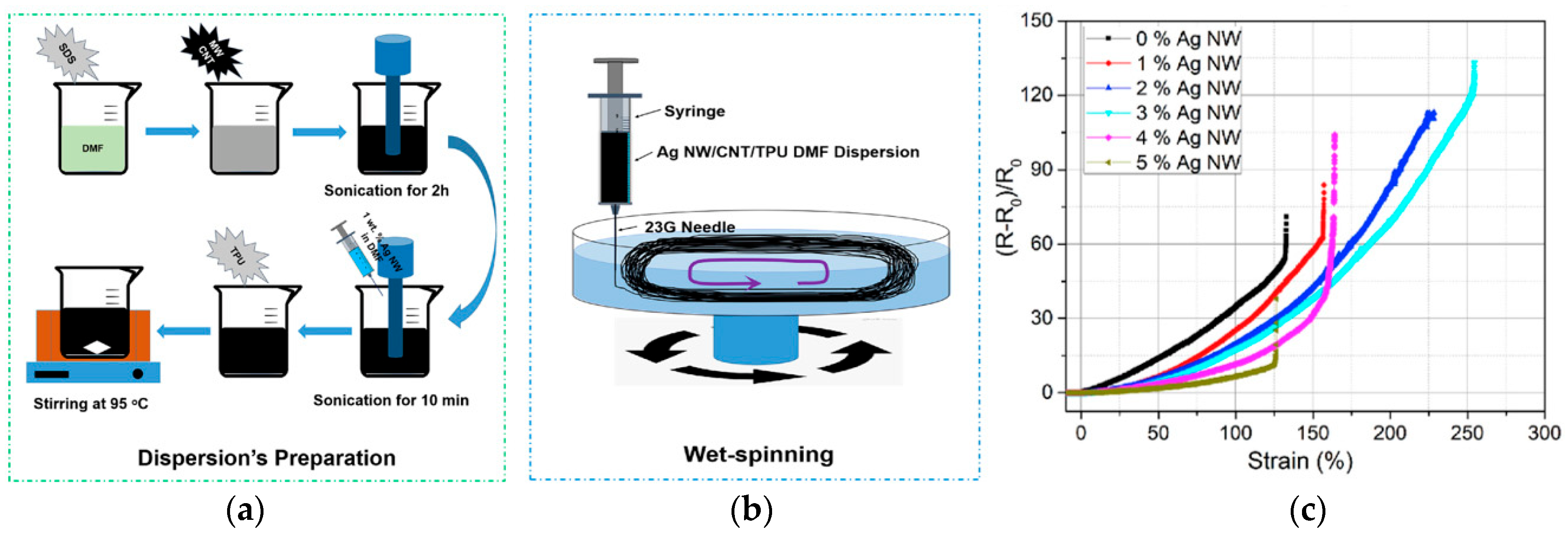
Traditional spinning techniques, such as wet spinning, dry spinning and melt spinning, are the most common methods to prepare a 1D stretchable conductive composite materials; they mix the conductive filler and the elastic matrix directly and uniformly, and then extrude it through the spinneret hole to a coagulating bath to form the composite fiber. Li et al. uniformly mixed Gr into SBS and prepared SBS/Gr composite fiber flexible strain sensors by a simple wet-spinning method, and the Gr content had a significant impact on the morphology, mechanical properties and electromechanical properties of the composite fiber (Figure 1) [70]. The fiber with the 5 wt% graphene content has a wide working strain, which reaches 100%. However, its sensitivity increases with the increase in strain, and the sensitivity within 50% strain is changeable at different stretching speeds. He et al. proposed multiwalled carbon nanotube/thermoplastic polyurethane (MWCNT/TPU) fibers by wet spinning [71]. The gauge factors (GF) of the MWCNT/TPU fiber are about 550 and 2800 in the strain ranges of 1 to 4% and 5 to 100%, respectively. The strain of the MWCNT/TPU fibers decreases significantly under large hysteresis after multiple stretching–releasing cycles, indicating poor sensing repeat stability. At the same time, the influence of different weight ratios of MWCNTs to TPU on the mechanical and electrical properties of composite fibers has been studied. It was found that the concentration and arrangement of MWCNT would change the working strain range and GF of the sensor [72]. Wang et al. manufactured a fiber strain sensor with a wide response range (320%) and a fast response time (<200 ms) based on MWCNTs and TPU by a simple wet-spinning method [39]. However, the electrical response of the MWCNT/TPU strain sensor decreased slightly in the initial stage when multiple stretching–releasing cycles were carried out at 100% strain, and it exhibited unstable sensitivity at the same time. To improve the conductivity and the stability of the conductive network, hybrid conductive fillers have been used to achieve a composite synergistic effect to prepare strain-sensing fibers. For instance, Zhang et al. demonstrated a highly conductive AgNW/MWCNT/TPU composite fiber by wet spinning, in which MWCNTs were regarded as the sensitive materials and silver nanowires were used to improve electrical conductivity [73]. When the contents of AgNWs reached the optimal amount (3%), the working strain range was 254%, and the conductivity was 0.0803 S/cm (Figure 2). Compared with single-filler composite fibers, the increase in AgNWs improves the conductivity and working strain range of the composite fiber, but its sensitivity decreases. In the case of a strain range of 50–150%, the relative resistance change of the sensor continues to decrease in stretching–releasing tests within 1000 s, showing poor stability.
3.1.2. Selective Localization of Conductive Materials
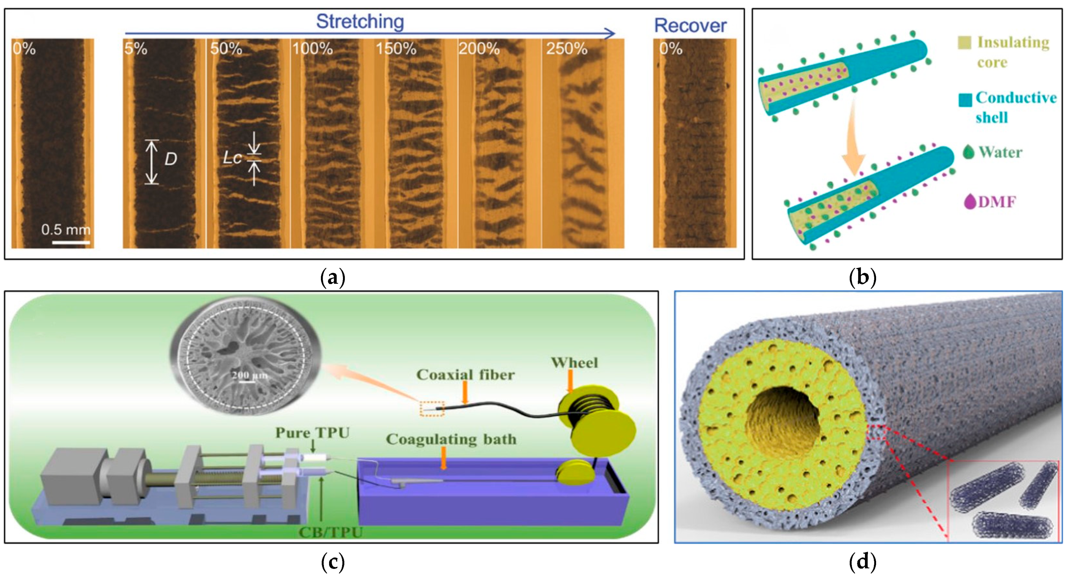
The conductive network was also designed by controlling the distribution of the fillers, such as selective positioning in multiple phases to form a co-continuous structure or a sea-island structure. In this case, the conductivity of the composite is improved by forming a double or triple permeation structure in the polymer matrix. The selective positioning of the fillers at the interface of the co-continuous polymer structure can further reduce the filler content, which is required to form the continuous conductive network. Zhou et al. used the coaxial wet-spinning method and post-treatment process to prepare the thermoplastic elastomer/single-walled carbon nanotube (TPE/SWCNT) ribbon coaxial fiber with good stretchability and high sensitivity (Figure 3a) [38]. The strain sensor composed of this fiber has a GF of 48 at 0–5% strain and a GF of 425 at 20–100% strain; a linear change cannot occur in in the full strain range. Tang et al. designed a stretchable core sheath fiber using a one-step coaxial wet-spinning assembly method, in which a high-stretch polymer elastomer Ecoflex wrapped CNT/Ecoflex composite material [74]. Similar to traditional cables, the outer insulating sheath effectively avoids short circuits and the falling off of conductive fillers. At the same time, it can have good conductivity under a low permeability threshold (0.74 vol%). Strain sensors made of this fiber achieve a high sensitivity of 1378 under 300% strain and show high durability under 100% strain, but they exhibit low sensitivity in a small strain range, non-linear resistance change and obvious overshoot behavior. Yue et al. demonstrated a highly stretchable TPU-CB@TPU fiber strain sensor with a porous core–sheath structure through the coaxial wet-spinning method (Figure 3b,c) [37]. Due to the countercurrent diffusion and coagulation of the solvent, this fiber has a porous structure with a wide strain range. The highest GF is 28,084 when the strain is 204%. However, its sensitivity is not large enough in a small strain range, and the resistance change gradually declines over multiple cycles of stretching. A coaxial fiber with an outer layer of MXene/PU composite and an inner layer of PU was prepared by Seyedin et al. [75]. Compared with the non-coaxial composite fiber, the coaxial fiber shows a larger strain range, a smaller data drift, and an improvement in the cyclic stability of the sensor response. Gao et al. fabricated a coaxial stretchable composite fiber with a double-layer hollow structure (Figure 3d), in which the conductive outer layer has a CNT/TPU composite as the sensitive area, and the insulating inner layer is made of pure TPU with a hollow core to serve as a flexible support [76]. The prepared composite fiber (TPU-8CNT@TPU) has an ultralow percolation threshold (0.17 wt%), good durability, and small compression deformation that can be detected. With an increase in the stretching speed, the relative resistance differently changes under the same strain. Additionally, there is an obvious shoulder phenomenon, which may disturb signal identification in an accurate strain monitoring. However, the reason for this shoulder phenomenon is still not clear. The mainstream is attributed to the competition between the destruction and reconstruction of CNT conductive networks in the fiber, which needs further verification.
The characteristics of various fiber-based strain sensors prepared by spinning technology are summarized in Table 4. In general, the preparation of stretchable conductive composite fibers as strain sensors by mixing conductive materials and spinning is a process technology that can be produced on a large scale and is widely used in industry. However, the addition of conductive filler will enhance the rigidity of the elastic matrix, and shrink the tensile strain range of the fiber, which leads to the narrow working strain range of the fiber sensor. On the contrary, if the amount of conductive material is too low, the conductivity of the composite fiber will also limit its working strain range. Therefore, there is a paradox between the conductivity and the working strain range of the stretchable conductive fiber, which needs to be balanced. According to the percolation theory [60,77,78,79,80,81], the content of conductive materials in stretchable conductive composites has a percolation threshold. When the percolation threshold is exceeded, the polymer elastomer changes from an insulator to a conductor, and the conductivity increases with the increase in the content of conductive materials. When the content is near the percolation threshold, the sensitivity of the material is at its greatest [82]. Therefore, it is still a huge challenge to achieve a high strain range and high sensitivity at the same time for conductive composite fibers. In addition, there is a limit on the production costs of practical commercial applications with the increase in conductive fillers. To reduce the permeation threshold while achieving high conductivity, different strategies have been studied [50,83,84], such as functionalizing conductive fillers’ surfaces, increasing the aspect ratio of fillers, controlling the arrangement of fillers, and using different mixture of fillers. However, such permeation-based composite strain sensors rarely exhibit good linearity. When the composite fiber is stretched, its resistance is mainly caused by changes in geometry and tunnel theory [37,39,85]. With an increase in tunneling distance and the destruction of the conductive path, the resistance of composites increases significantly during the tensile process. The maximum GF usually occurs when the conductive material content is close to the permeation threshold. Other shortcomings of strain sensors made of composite fibers include hysteresis, fatigue and so on, which are mostly due to the viscoelasticity and elastic recovery rate of composite fibers.

Table 4.
Characteristics of conductive composite fiber-based strain sensors prepared by spinning technology.
Table 4.
Characteristics of conductive composite fiber-based strain sensors prepared by spinning technology.
| Structure | Substrate | Sensitive Materials | Breaking Stress and Strain | Conductivity | Strain Range | GF | Repeatability | Linearity | Response Time | Ref. |
|---|---|---|---|---|---|---|---|---|---|---|
| Monofilament | SBS | Gr | 10.16 MPa; 910.83% | N/A | 100% | 10,083.98 (73–100%) | 2500 (20%) | N/A | N/A | [70] |
| Monofilament | TPU | MWCNTs | 28 MPa; 320% | N/A | 100% | 2800 (5–100%) | N/A | N/A | N/A | [71] |
| Monofilament | SIBS | P3HT | 11.4 MPa; 975% | 0.38 S/cm | 770% | 20 (12.25%) | N/A | N/A | N/A | [86] |
| Monofilament | TPU | MWCNTs/ AgNWs | 32.49 MPa | 0.803 S/cm | 250% | 13 (50–150%) | N/A | N/A | N/A | [73] |
| Ribbon and coaxial | TPE | SWCNTs | N/A | N/A | 100% | 425 (100%) | 3250 (20–100%) | R2 = 0.98 (20–100%) | N/A | [38] |
| Core–sheath | Ecoflex | CNTs | N/A | N/A | 330% | 1378 (330%) | >10,000 (100%) | N/A | >300 ms (100%) | [74] |
| Porous | TPU | CB | 2.15 MPa | N/A | 380% | 28,084 (204%) | 11,000 (60%) | N/A | 200 ms | [87] |
| Coaxial | PU | MXene | 20.3 GPa | N/A | 152% | 238 (50%) | 1000 (50%) | N/A | N/A | [75] |
| Hollow | TPU | CNTs | 2.92 MPa; 476% | N/A | >350% | 1344.1 (200%) | 10,000 (100%) | N/A | 167 ms | [76] |
3.2. Conductive Coated Fibers
3.2.1. Microcrack Structure
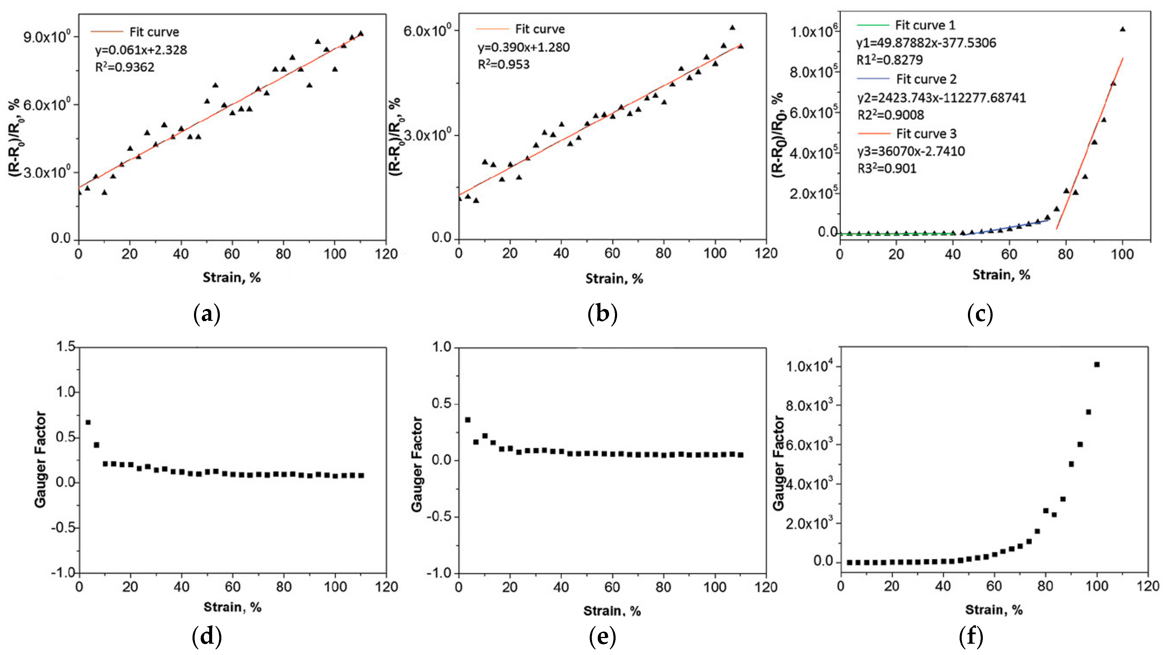
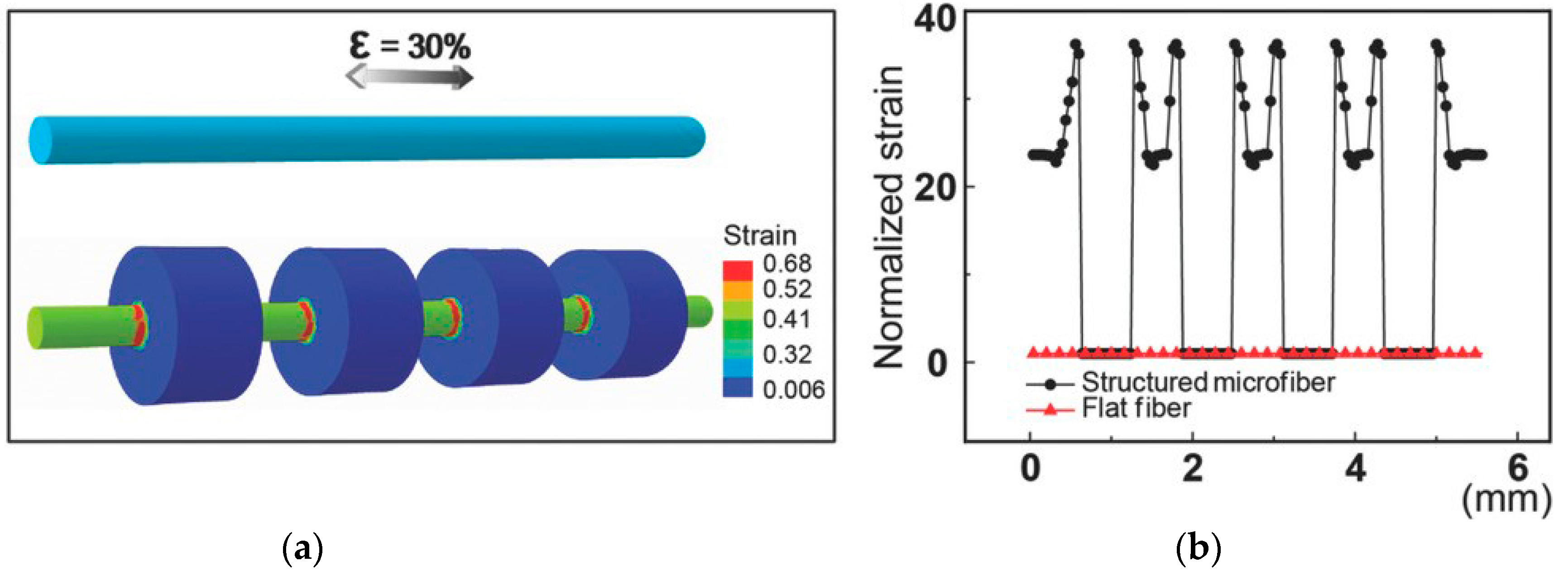
Coating conductive materials on stretchable fibers or yarns is another way to prepare one-dimensional strain sensors by dipping, spraying, and in situ chemical polymerization, etc. The dip-coating method is one of the easiest and most widely used methods among them, due to its simple, fast and cost-effective characteristics. For example, Lee et al. reported a conductive PU multifilament coated uniformly AgNPs by an in situ reduction method, with low initial resistance (0.16 Ω/cm) (Figure 4a,b) [45]. AgNPs are uniformly distributed inside the multifilament and form a dense shell on the outer layer. The GF of the strain sensor reaches about 9.3 × 10⁵ (under 450% strain) when the strain sensor is first stretched, while the GF decreases to 659 (under 450% strain) after subsequent stretching. Although the strain sensor has high sensitivity and wide strain range, its sensitivity is unstable and its linearity is poor. Generally speaking, the microcrack structure constructed by the strain sensor in tension is an effective method to achieve a sensing response and high sensitivity of sensors. However, the microcrack structure is usually limited by strain range. Compared with monofilament, the increase in the number of multifilament structures greatly widens its working strain range according to the theory (Figure 4c,d) [45]. Eom et al. first polymerized conductive PEDOT on polyester (PS) fibers by in situ polymerization to prepare conductive coated fibers, and then embedded this conductive fiber into fabrics to manufacture textile-based strain/touch/pressure sensors and user interface (UI) equipment [36]. Due to the multifilament structure of its PEDOT/PS fiber, the resistance of the sensor tends to fall with the increase in strain, which is contrary to the common trend. During stretching, the overall conductivity of the PEDOT/PS multifilament increases, and the PEDOT/PS monofilament exhibits the opposite behavior. Liu et al. designed a monofilament strain sensor with a beaded structure using the Plateau–Rayleigh instability principle. The way to control the strain distribution along the fiber axis is by adjusting the size of the microbeads and the distance between the microbeads (Figure 5) [88]. This design effectively causes strain concentration and amplifies the local strain. Compared with a single uniform monofilament, the sensitivity of the sensor with a beaded structure is significantly improved. Overall, the sensitivity of the sensor with the crack effect usually increases significantly and then decreases, which is a characteristic of nonlinear sensing [45]. Due to the destruction and shedding of the conductive layer, the sensor also exhibits a certain amount of hysteresis and poor cycle stability.
3.2.2. Wrinkle Structure
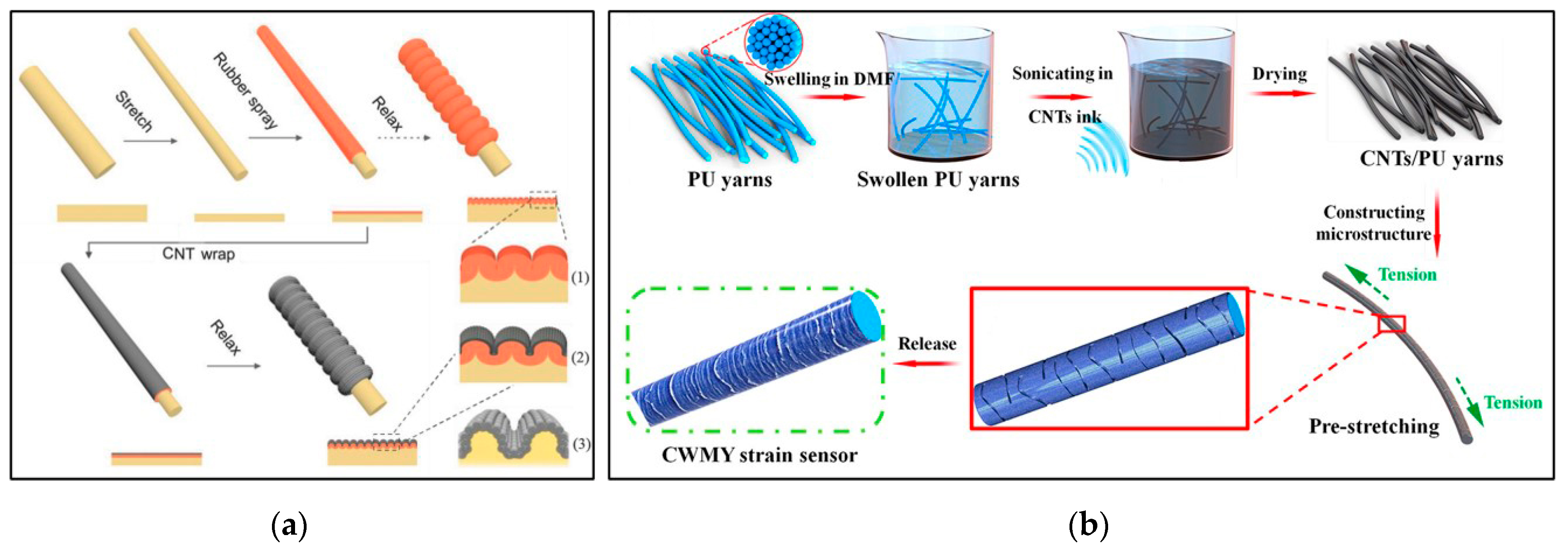
In order to improve the workable strain range, a conductive coating with a wrinkle structure was added to the fiber surface to design a flexible strain sensor. Wang et al. designed a highly stretchable NTSm@rubber@fiber strain sensor with a dual-sheath buckling structure by the pre-stretching method, in which NTS is the carbon nanotube sheets and m represents the number of NTS layers (Figure 6a) [89]. The elastic support fiber coaxially coated a curved rubber intermediate layer and a curved NTS conductive layer. At the same time, the GF of the sensor was controlled by changing the manufacturing parameters to adjust the buckling structure, but its overall sensitivity values were very low, only 0.5 (0–200%) and 0.14 (200–600%). The design of a wrinkle structure makes the strain sensor bear high tensile deformation without destroying the conductivity of the material, thereby increasing its sensing range. However, it also causes a small resistance change in the stretched state, showing lower sensitivity. As shown in Figure 6b, CNT ink/PU yarns with a wrinkle-assisted crack microstructure were created by Sun et al. [90]. The yarn sensors have an ultralow detection limit and excellent repeat stability. As mentioned above, the complex and multistep manufacturing process poses challenges to realize a large-scale production of strain sensors.
3.2.3. Multilayer Structure
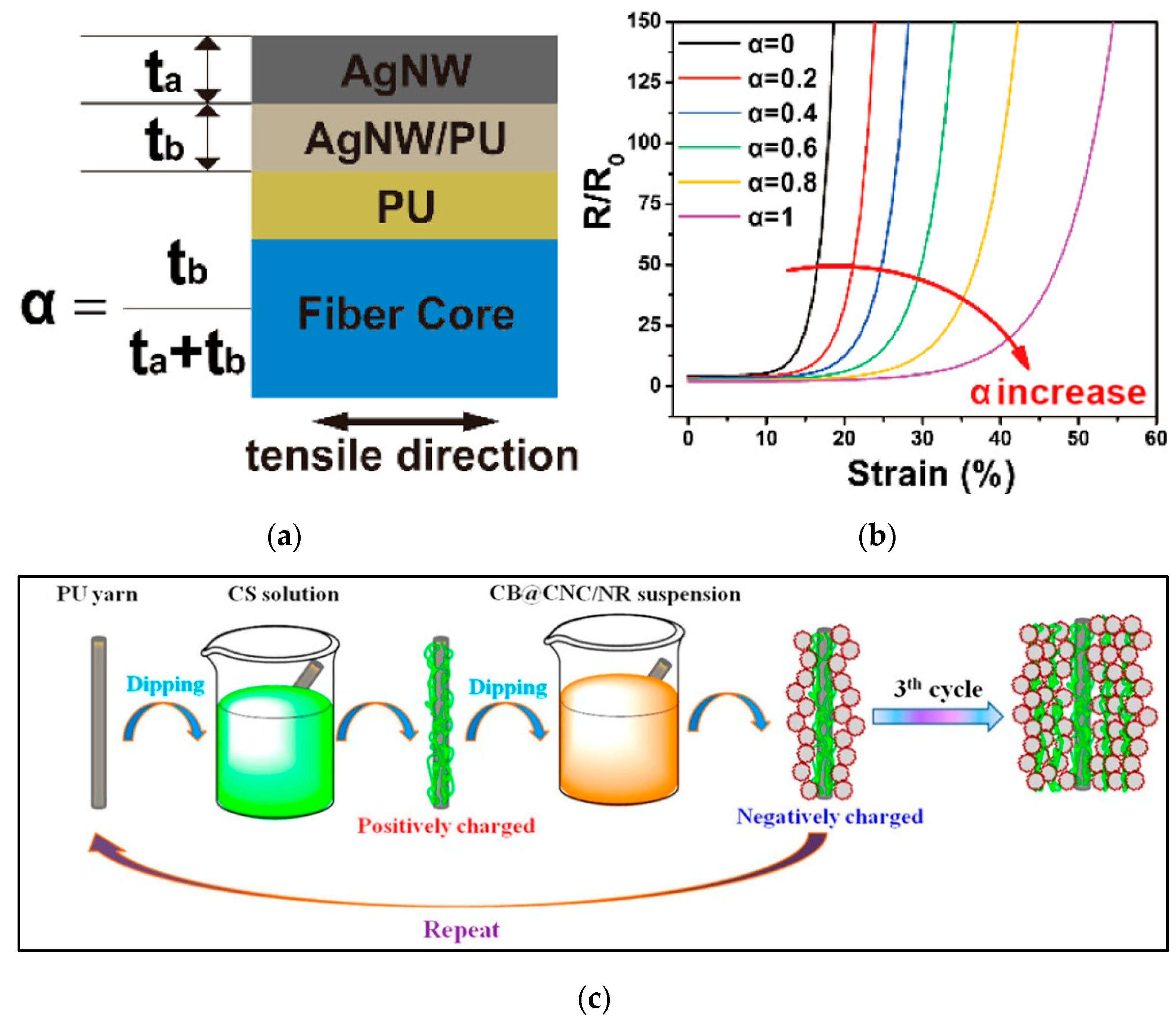
Building a multilayered structure at the fiber scale is another way to design flexible strain sensors. Cao et al. introduced a AgNW/PU fiber with a composite multilayer structure by using an adhesive layer with adjustable adhesion to adjust the interface adhesion and fiber microstructure (Figure 7a) [91]. The GF and stretchability of the strain sensor were adjusted by changing the interface layer combination (Figure 7b). However, its sensitivity was weak and the resistance response was nonlinear. After 100 and 1000 cycles of stretching at 10% strain, the drift rate values of the relative resistance of the sensor were 29.4 and 53.1%, respectively, showing poor repeatability. Liu et al. reported the silver plating polyurethane filaments (SPPF) with good electrical resistivity (4.5 ± 0.1 Ω/cm) [92]. These AgNPs are bound to the surface of the filament by polydopamine, which remarkably improves the bonding between the conductive material and the fiber interface, but the nonlinear error and hysteresis of the SPPF strain sensor are up to 29.3 and 34.3%, respectively.
The layer-by-layer (LBL) assembly method has been used to develop strain sensors with multilayer structures. The LBL assembly method has been reported as an effective method for manufacturing carbon-based films. Instead of simple deposition, this process includes repeated immersion and evaporation, and various reactions such as electrostatic interactions, hydrogen bonding, or covalent bonding to enhance the adhesion of the interface [93]. Li et al. prepared a strain sensor using graphene/polyvinyl alcohol (Gr/PVA) composite material as the outer layer conductive sheath and polyurethane as the elastic core fiber [94]. When the Gr concentration is 1wt% and the number of coatings is nine, the composite coated fiber has the maximum GF (86.9) and a wide strain range (50%) and good linearity (R2 = 0.97). However, the GF of the strain sensor only reaches more than 40 in the 50% strain extension–release cycles, and the repeatability is 1.81% and the hysteresis error is 9.08% over 100 cycles. A CPC@PU yarn strain sensor was prepared by Wu et al. (Figure 7c) [34], in which the ultrathin conductive CPC layer consists of positively charged chitosan (CS) and negatively charged carbon black (CB)/cellulose nanocrystal (CNC)/natural rubber (NR) nanohybrid. Although this fiber sensor based on CPC coating detects strains as low as 0.1% and shows a GF of approximately 38.9 at 1% strain, it is not reliable for detecting strains larger than 5%. Li et al. proposed a core–sheath structure strain sensor, which is composed of PU core yarn, a highly conductive multilayer sheath material, namely graphene nanosheets/thin gold film/graphene nanosheets (GNSs/Au/GNSs), and PDMS coating. This multilayer structure combination can simultaneously achieve high sensitivity, wide strain-sensing range and good waterproof performance. In 10,000 stretch–release cycles at 50% strain, its stability is excellent [42]. Although the LBL method improves the adhesion of the coating, it takes multiple cycles of treatment to achieve a high conductivity due to the introduction of the insulating polymer.
The characteristics of fiber strain sensors prepared by coating technology are summarized in Table 5. In general, the coating method is easy to implement and the 1D strain sensors produce via this method show good sensing performance. As the mechanical properties of conductive coatings and elastic substrates are inconsistent, conductive coatings propagate small and dense microcracks, which destroys conductive networks and causes the changes of resistance. However, the poor adhesion and the mechanical mismatch between the elastic substrate and the conductive coating often leads to degradation of the sensor response. Therefore, it is still a big challenge to achieve high linearity and cycle stability by a simple coating. Due to the irreversible fracture and shedding of the conductive layer, it is very necessary to explore the stress distribution and interface strength between the conductive coating and the substrate. Although the added adhesive (like the LBL method) has improved adhesion, the fatigue durability of the strain sensor is still a challenge. Additionally, there is a lack of systematic studies on how to control the crack propagation and stability, and on how it affects the sensing performance of strain sensors.
Table 5.
Characteristics of fiber strain sensors prepared by coating technology.
| Method | Structure | Substrate | Adhesive | Sensitive Materials | Breaking Stress and Strain | Conductivity | Strain Range | GF | Repeatability | Linearity | Response Time | Ref. |
|---|---|---|---|---|---|---|---|---|---|---|---|---|
| In site reduction | Multifilament | PU | N/A | AgNPs | N/A | 0.16 Ω/cm | 200% | 659 (150–200%) | 10,000 (10%) | N/A | N/A | [45] |
| In situ polymerization | Multifilament | PS | N/A | PEDOT | 0.813 ± 0.057 GPa | 600 Ω/cm | 70% | 0.244 (70%) | 1000 (20%) | N/A | N/A | [36] |
| deposition | Beaded | PDMS | N/A | Au/CNTs | N/A | N/A | 125% | low | 5000 (30%) | R2 = 0.96 | N/A | [88] |
| Spraying | Double sheath buckle | SBS | SGE | NTS | N/A | N/A | 600% | 0.14 (200–600%) | 5000 (100%) | N/A | 80 ms | [89] |
| Dip coating | Wrinkle assisted | PU | N/A | CNTs | N/A | N/A | 200% | 1344.1 (200%) | 10,000 (30%) | R2 = 0.99 (0–50%) | <88 ms (1%) | [90] |
| Roller transfer | Core–sheath | PU | PU | AgNWs | 38.24 MPa; 980% | 240.36 S/cm | 60% | 5~9557 | 10,000 (10%) | N/A | 120 ms (0.5%) | [91] |
| In situ polymerization and reduction | Core–sheath | PF | PDA | AgNPs | 300 cN; 405.9% | 4.5 Ω/cm | N/A | N/A | N/A | nonlinear error < 29.3% | N/A | [92] |
| LBL | Core–sheath | PU | CS | CB/CNC/NR | N/A | 4.1 MΩ/cm | 1% | 38.9 (1%) | 10,000 (1%) | Good linearity | N/A | [34] |
| LBL and sputtering | Core–sheath | PU | PVA | GNSs/Au/GNSs | N/A | N/A | 75% | 661.59 (50%) | 10,000 (50%) | R2 = 0.983 (0–50%) | N/A | [42] |
3.3. Conductive Composite Yarns
3.3.1. Wrapped Structure
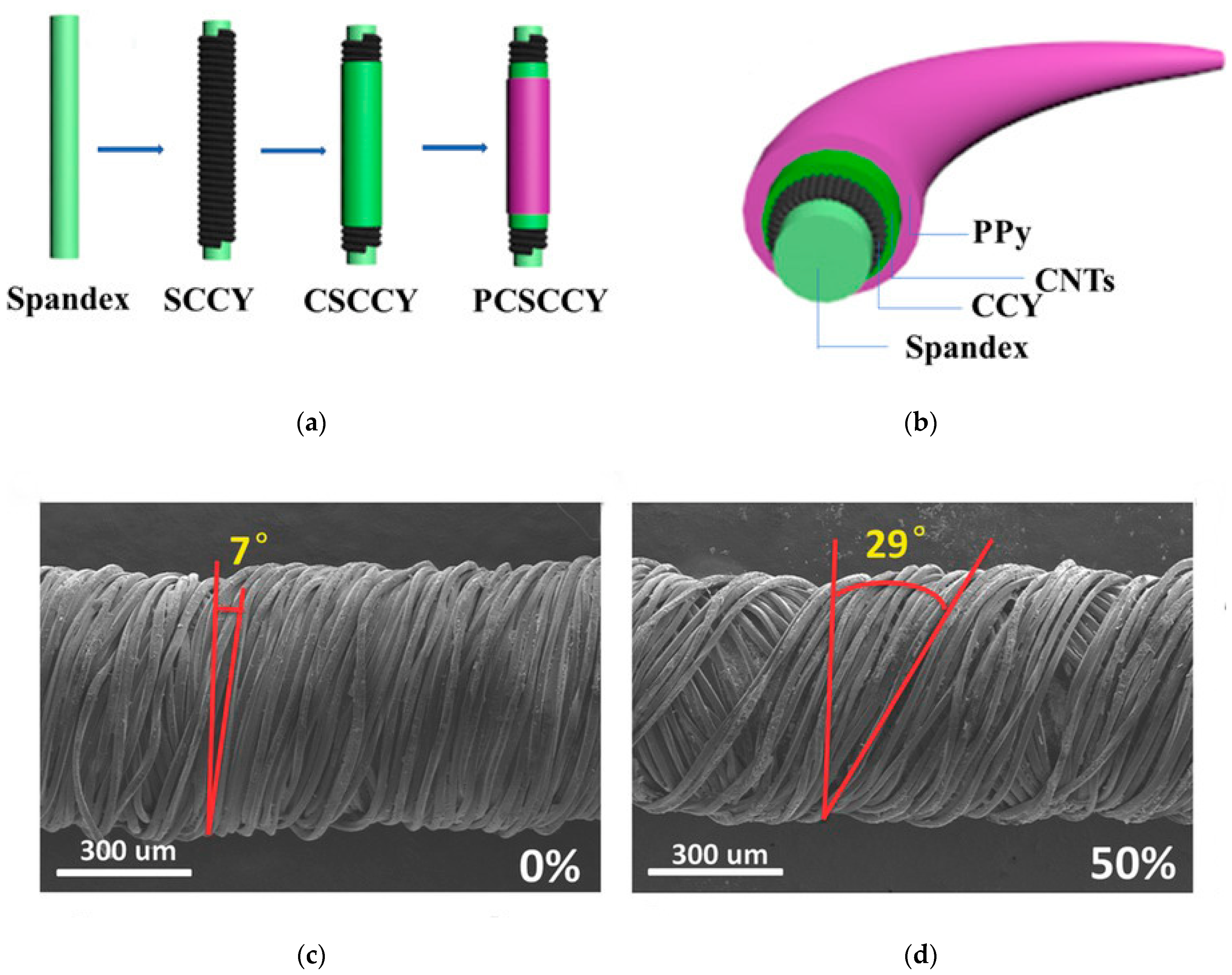
The working strain range of the one-dimensional sensor may be limited if the resistance is changed only by the cracks on the surface of the fiber or yarn. To improve its working strain range and stability, the structural adjustment of the yarns has also been explored. Cai et al. prepared a cotton/CNT core-spun yarn sensor by coating CNTs and depositing PPy on the surface (Figure 8a,b) [95]. The yarn has a broad strain range, up to 350%, but its GF is small, only 5.11 and 3.41 at strains of 0–50% and 50–350%, respectively. Cheng et al. developed a simple and mass-produced graphene-based composite yarn with a compression spring structure by plasma treatment and dipping (Figure 8c,d) [96]. The minimum and maximum detection limits of this double-wrapped composite yarn are 0.2 and 100% strain, respectively. Additionally, the signal response speed is fast (<100 ms). After several stretching cycles under 30 and 50% strain, the performance is stable, but its sensitivity is very low. Zhu et al. introduced curcumin-assisted chemical deposition (ELD) to prepare a helical yarn with a metal coating, and established a model to analyze its sensing mechanism [46]. The relative resistance change of the yarn can be expressed as a function related to the tensile strain ε, including θ(ε), g(ε) and (θ is the winding angle, g is the average gap of the separated winding, is the resistance of an independent winding). As mentioned above, the yarn strain sensors based on geometric change sensing have excellent linearity, low hysteresis, high stability and a large sensing range, but their sensitivity is limited [15].
3.3.2. Braided Structure
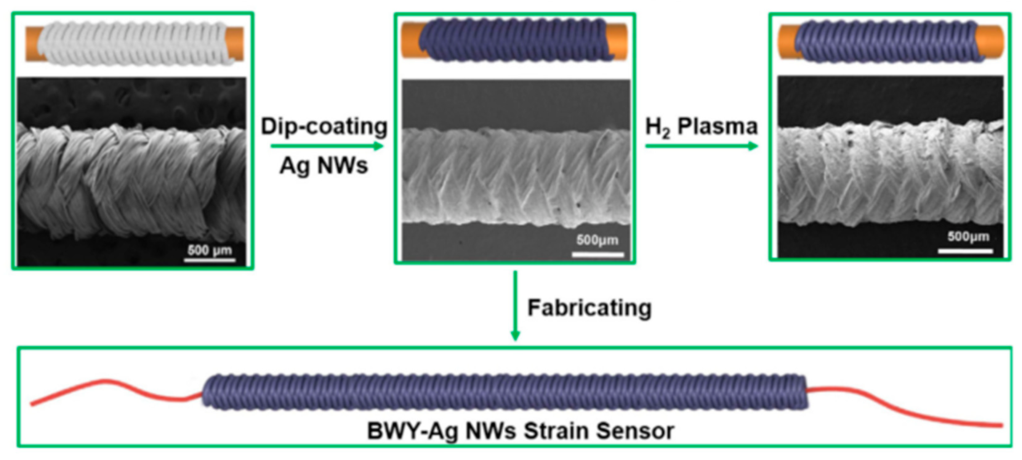
Another design is to use braided yarns to fabricate yarn-based strain sensors. Shi et al. reported a sensor (BWY-AgNWs) composed of stretchable yarns with a braided structure and silver nanowires by dip coating (Figure 9) [97]. The fiber sensor can not only detect various deformations such as stretching, torsion, and bending, but also has a high stable sensitivity (GF = 65) in a larger sensing range (strain can reach 100%). However, due to the insufficient recovery of the microstructure and the brittleness of the AgNWs film, the microcracks cannot be completely merged after release, resulting in the poor repeatability of the strain sensor during multiple cycles of stretching. Furthermore, the high hysteresis of the strain sensor makes its strain response slow, which limits its wearable application. Yang et al. proposed a PET/AgNW/PDMS yarn sensor with braid yarns as the substrate, AgNW as the active material and PDMS as the protective layer by dip coating [98]. The yarn sensor has high conductivity and a wide range of stretchable strain. However, the resistance change does not increase monotonously with the increase in strain, instead of a downward trend after 40% strain. In addition, the relative resistance changes in PET/AgNW/PDMS yarns with an upward trend show relatively instability during multiple stretching and bending cycles. Pan et al. designed a yarn sensor with a core–sheath yarn structure, in which a braided composite yarn coated with CNTs is used as the core (BYs-CNT) and electrospun polyurethane nanofibers are used as the sheath [35]. This kind of combination of the yarn has extremely high sensing sensitivity (maximum GF up to 980) and long-term stability, but poor linearity. Additionally, the yarn preparation process is complicated and cannot be easily produced en masse. Similarly, the relative resistance change shows a downward trend after the strain exceeds 40%, due to the changes in the braid angle and contact area of braided yarns PET during the stretching process.
3.3.3. Helical and Winding Structure
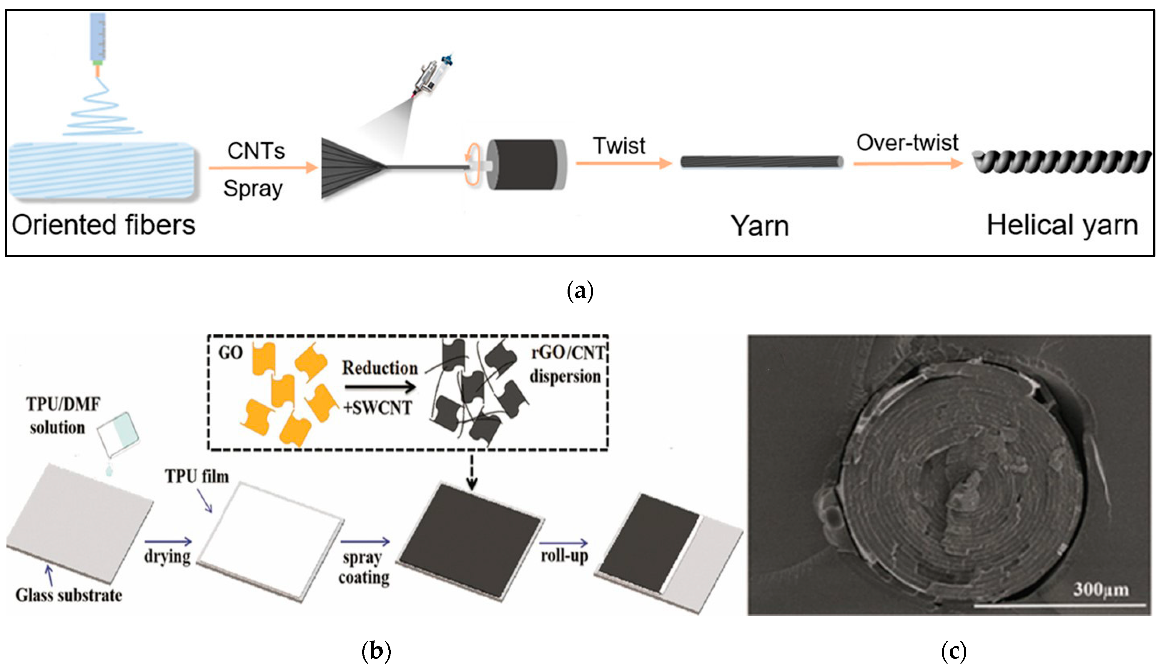
In addition to fancy yarn, unconventional yarn sensors have been formed by twisting and winding conductive coated films, which remarkedly enhance the tensile strain range of one-dimensional sensors. Compared with the conventional planar wave structure, the coil structure has greater stretchability because the local stress is suppressed during the stretching process and the local maximum strain is reduced due to the non-planar motion of the coil [99]. Ultrahigh stretchable conductive helical yarn with CNT/PU nanocomposite fiber helical yarn was prepared by simple electrospinning, spraying and twisting processes (Figure 10a) [99]. With the help of the synergistic effect of the flexible polymer chain and the nanofiber spiral coil structure, the CNT/PU helical yarn will break the limitation of material stretchability due to its rigidity and excellent stretchability. Its recovery is within 900% strain, and the maximum of tensile elongation can reach 1700%, while its sensitivity is very low. Xie et al. designed a SWCNT-RGO/TPU spiral layered composite yarn by spraying and winding technology (Figure 10b,c) [100]. Due to the special spiral layered structure of the composite yarn, the conductive layer is wrapped and protected by the elastic polymer layer, and there is no obvious interruption or crack on the surface of the yarn. Compared with the SWCNT-RGO/TPU thin-film sensor, the yarn sensor has a wider working strain range and has five linear regions. In the 50% tensile strain cycles, the relative resistance of the sensor continued to increase during the initial 100 cycles and then began to stabilize.
The performance of yarn-based strain sensors with different structures are summarized in Table 6. On the basis of the coating, improving the linearity and stability of the strain sensor by changing the yarn structure is an excellent method because the resistance change mainly depends on the structure of the composite yarn. For example, in terms of wrapped yarn-based sensors, the decrease in the contact of the spiral winding leads to an increase in resistance, but this also reduces the sensitivity and working strain range to a certain extent. Therefore, it is necessary to discuss the influence of structural changes on the sensing performance so that the yarn strain sensor has balanced performance indicators.
Table 6.
Characteristics of various yarn-based strain sensors.
| Method | Structure | Substrate | Sensitive Materials | Breaking Stress and Strain | Conductivity | Strain Range | GF | Repeatability | Linearity | Response Time | Ref. |
|---|---|---|---|---|---|---|---|---|---|---|---|
| Dip coating and in situ polymerization | Core-spun yarn | PU/cotton | CNT/PPy | >7 N; >300% | 310 Ω/cm | 350 | 5.11 (0–50%); 3.41 (50–100%) | N/A | Linearity at 0–50% and 50–350% strain, respectively | N/A | [95] |
| Dip coating | Wrapped yarn | PU/PE | Gr | 29.14 MPa; 676% | 0.012 S/m | 0.2–100% | 3.7 (50%) | 10,000 (30% and 50%) | N/A | <100 ms | [96] |
| ELD | Wrapped yarn | PU | Cu | N/A | 0.2 Ω/cm | 50% | N/A | 5000 (50%) | Good linearity | N/A | [46] |
| Dip coating | Braided yarn | PU/PET | AgNWs | N/A | 0.5 Ω/cm | 108.92% | 767.50 (97.28–108.92%) | 4000 (30%) | R2 = 0.975 (97.28–108.92%) | <100 ms (0.5%) | [97] |
| Coating | Braided yarn | Rubber/PET | AgNWs | N/A | 3 Ω/cm | 100% | 11.4 (100%) | 1700 (30%) | N/A | N/A | [98] |
| Dip coating | Braided yarn | Rubber/PET | CNT | 44N; 350% | 0.12 kΩ/cm | 44% | 980 (29–44%) | 1000 (20%) | N/A | 200 ms | [35] |
| Spraying | Helical coil | PU | CNT | 50.2 MPa; 1700% | N/A | 900% | N/A | 100 (200%) | N/A | N/A | [99] |
| Spraying | Helical layer | TPU | SWCNT/RGO | 40.0 MPa; 1237% | 821.8 S/m | 620% | 2160.4 (550–620%) | 1000 (50%) | N/A | N/A | [100] |
4. Interconnection and Packaging
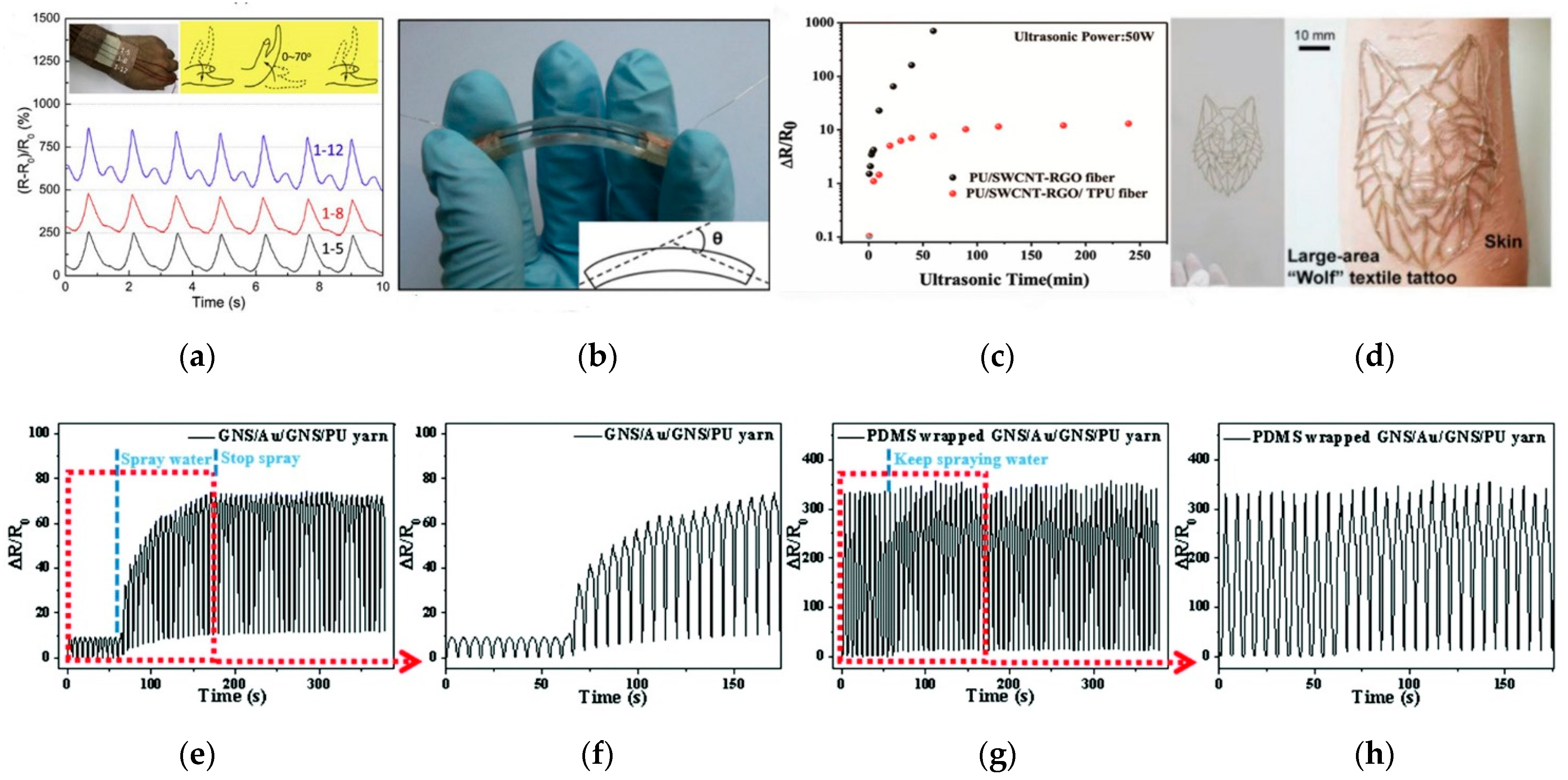
For wearable electronic applications, strain-sensing fibers or yarns need to be interconnected with other structural circuit elements or data acquisition circuits to fully integrate electronic devices. In wearable electronic devices, it is required that the sensing element must be firmly, elastically and electrically connected to the conductive wire or the data connector, and the interconnection point can still maintain high conductivity under considerable mechanical stress. In addition, the interconnection needs to robustly transmit the signal to the transmission board or processing electronics with minimal loss. At present, the common bonding methods in interconnection are mechanical bonding, physical bonding and chemical bonding [101,102]. However, the chemical bonding is not suitable for the interconnection of heterogeneous devices. Mechanical bonding refers to the use of friction to clamp or connect electronic components to wires, which is suitable for electronic connections of various conductive textiles. For fiber or yarn strain sensors, the mechanical bonding can be thread-to-thread knotting, or embroidery [103,104], stitching [72], or interlacing. Physical bonding includes soldering [105], adhesive bonding [96] and so on. The advantages and disadvantages of different interconnection methods are summarized in Table 7. Soldering is a process that the metal is melted with the high temperature to tightly coat and wrap electronic components to form a connection. However, few common fibers and yarns with conductive materials can withstand high temperature welding, and the narrow interface between the components is too small and difficult to handle. It is a method widely used in laboratories to connect strain-sensing yarns and functional components with conductive adhesives such as conductive glue and copper tape. For example, He et al. stitched MWCNT/TPU fibers onto an elastic bandage with cotton yarns to detect the wrist bending (Figure 11a) [72]. Both ends of the fibers were connected with conductive wires using silver paste and fixed by conductive tapes and medical tapes. Cheng et al. used conductive copper tape and silver paste to interconnect the two ends of graphene-based fibers as external electrodes with copper wires (diameter: 2 μm) (Figure 11b) [96]. Although this method is simple to operate, the electrical connection quality of the conductive adhesive is affected by humidity and temperature, and the copper tape is easily oxidized and has poor mechanical fatigue resistance, which may cause safety problems. Therefore, this type of interconnection often requires further suitable packaging protection.
Considering the stability and reliability of electrical interconnection and the durability of the strain sensor, the strain sensor is packaged for use. If strain sensors are integrated into clothing by textile technology, insulating coatings are considered to protect the sensors. For example, Li et al. used hydrophobic PDMS to pack the yarn-based strain sensor to achieve a good waterproof performance [42]. The relative resistance change values of the sensor without the hydrophobic packing increased significantly when the sensor was sprayed with water during the tensile cycle test (Figure 11e,f). On the contrary, the relative resistance change values changed slightly before and after water (Figure 11g,h). Xu et al. reported the encapsulated TPU/SWCNT-RGO/PU core–sheath fiber [106]. The ΔR/R0 of the encapsulated composite fiber firstly increased by 10 and then remained stable, showing great washability compared with the SWCNT-RGO/PU sensor (Figure 11c). Kwon et al. used self-healing polymers (T-SHPs) as self-adhesive and durable interconnection materials to encapsulate conductive sensing fibers. This method easily achieved the patterned design (Figure 11d), but also effectively improved the conductivity of the sensing fiber over the 1000 stretch cycles [107]. Additionally, it is easy and convenient to fabricate, but not safe and reliable, only being suitable for laboratory tests. In addition, the strain sensor can be directly integrated into fabrics by the hot-melting process. The hot-melting package is made of elastic thermoplastic materials, such as TPU hot-melting adhesives. The materials are heated to the melting temperature and cooled after molding. For instance, Bahadir et al. reported a waterproof textile transmission line with GoreTex® waterproof welding tape by hot air sealing [108]. From the perspective of structural mechanics, electronic packaging can be seen as a composite structure made of different materials (substrate-conductive coating-encapsulation layer), and the physical parameters between the layers will affect the average strain transfer rate and sensing performance. In addition, when the device is subjected to thermo-mechanical loads, the interface between these materials is the most prone to failure. This is due to the inherent stress concentration generated by the interface bonds between different materials and the free surface of the two materials. Under repeated external mechanical action, cracks are not limited to the interface, but also propagate and expand parallelly to the interface [109]. Therefore, the system integration of interconnected wires and strain sensors under high-level strain loads is still a huge challenge. Poor interfaces will not only cause serious errors, but also lead to low reliability of the entire sensor system. The mechanical and sensing properties of conductive yarns before and after encapsulation will change to a certain degree. However, there is currently a lack of comprehensive research on the effect of packaging process on the sensing performance of stretchable conductive fibers or yarns.
5. Application
Fiber- and yarn-based strain sensors exhibiting outstanding sensing performances have broad application prospects. In the healthcare industry, wearable strain sensors are installed or worn on different parts of a patient’s body, such as hands, fingers, waist and feet, to analyze posture and gait. The traditional sensor for human motion analysis is the accelerometer, but its rigid structure is not easy to integrate into clothing, and would be uncomfortable for wearers over long periods [110]. In addition, the performance of the accelerometer is easily interfered by the environmental magnetic field and temperature. Textile sensors are more comfortable and flexible in measuring human posture and movement with low cost. In particular, fiber or yarn strain sensors can be woven into fabrics that can be worn directly on various body parts, such as knees, elbows and fingers, without any support structure or frame. By contrast, the nanofiber mats and fabric sensors are usually integrated into clothing by adhesive binding and stitching. Fiber and yarn strain sensor devices can be used for a variety of applications without platform constraints and accurately monitor strain in a single direction. However, their electrical performances are still unsatisfactory for practical applications of consumer-level sensor systems. Additionally, it is essential to develop supporting circuit and algorithm to achieve wearable applications. For instance, the problem of resistance drift with time and repeated use can be solved in algorithms with periodic calibration. The performance of different strain sensors used to monitor human movement and human–computer interaction is compared in Table 8.
5.1. Human Motion Monitoring
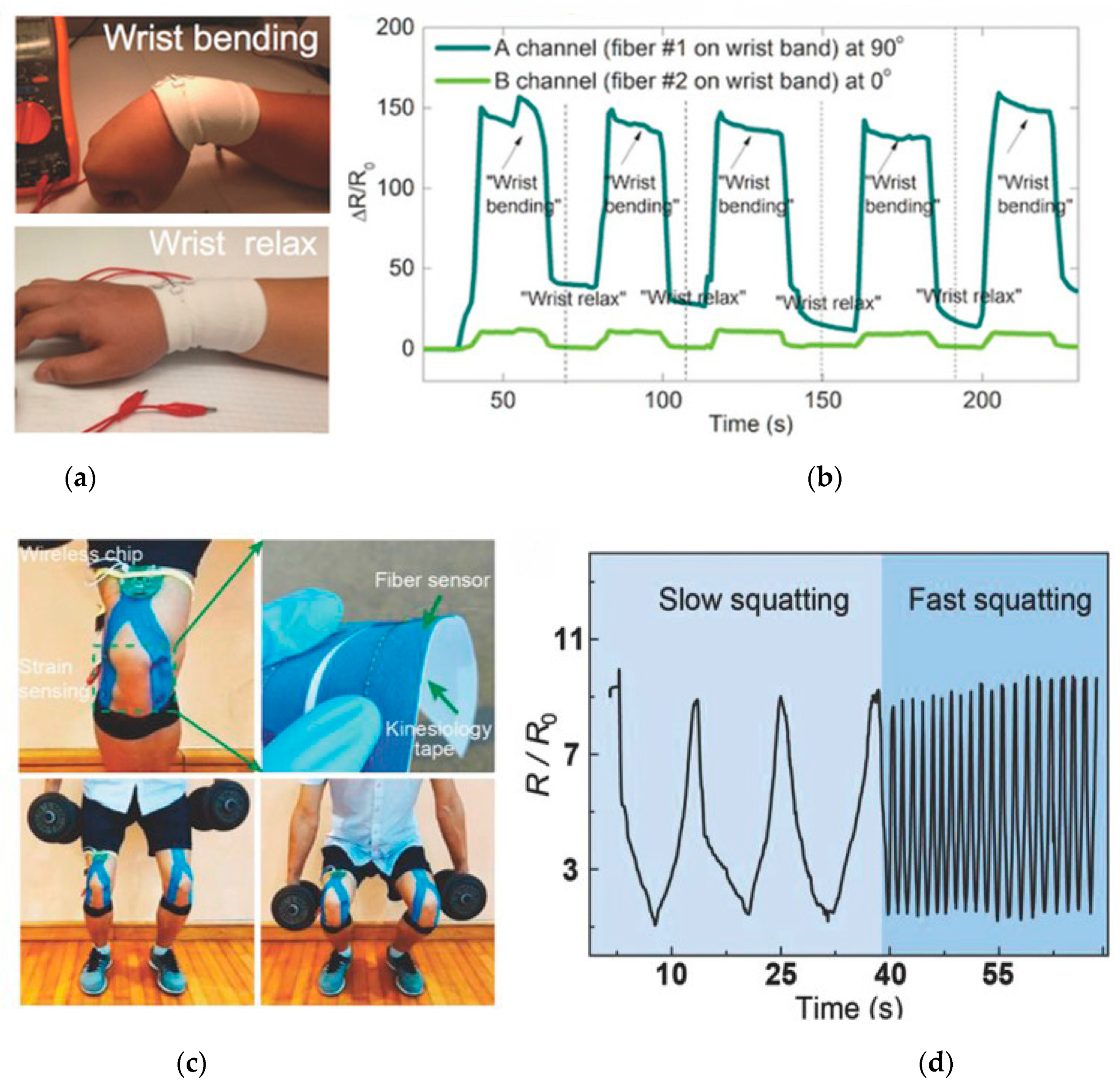
Generally, human motion detection can be classified into exercises with large strain (for example, limb bending or stretching) [118,119] and subtle movements with small strain (such as swallowing or emotional expression) [120]. According to clinical data, the flexion ranges of fingers or wrists, elbows and knees of people with every age group are different, ranging from 0 to 90°, 0 to 160°, and 0 to 130°, respectively [121,122]. Therefore, the large deformation experienced by the human skin ranges from 0 to 100% strain, and thus the corresponding flexible strain sensors require a wider workable strain range. For example, Li et al. used epoxy adhesive to connect two coaxial fibers to the wristband in a perpendicular manner [38]. The sensor monitors the bending and relaxation of the wrist to show a repeatable switching signal (Figure 12a,b). By stitching fibers into the sleeves of the jacket, the stretching, pressing, folding and twisting motions of the sleeves create different signals. Liu et al. reported an elastic garment with a stretchable fiber-based strain sensor can sensitively detect the bending motion of the knee (Figure 12c,d) [88]. Fiber sensors can be snugly integrated into textiles, so the wearer can move comfortably and freely with accurate sensor monitoring. Jiang et al. used two thread-based sensors to monitor the head motion, and characterized the electrical signals by using a machine learning algorithm to realize head motion classification [115]. The accuracy of a set of nine head directions is about 92%.
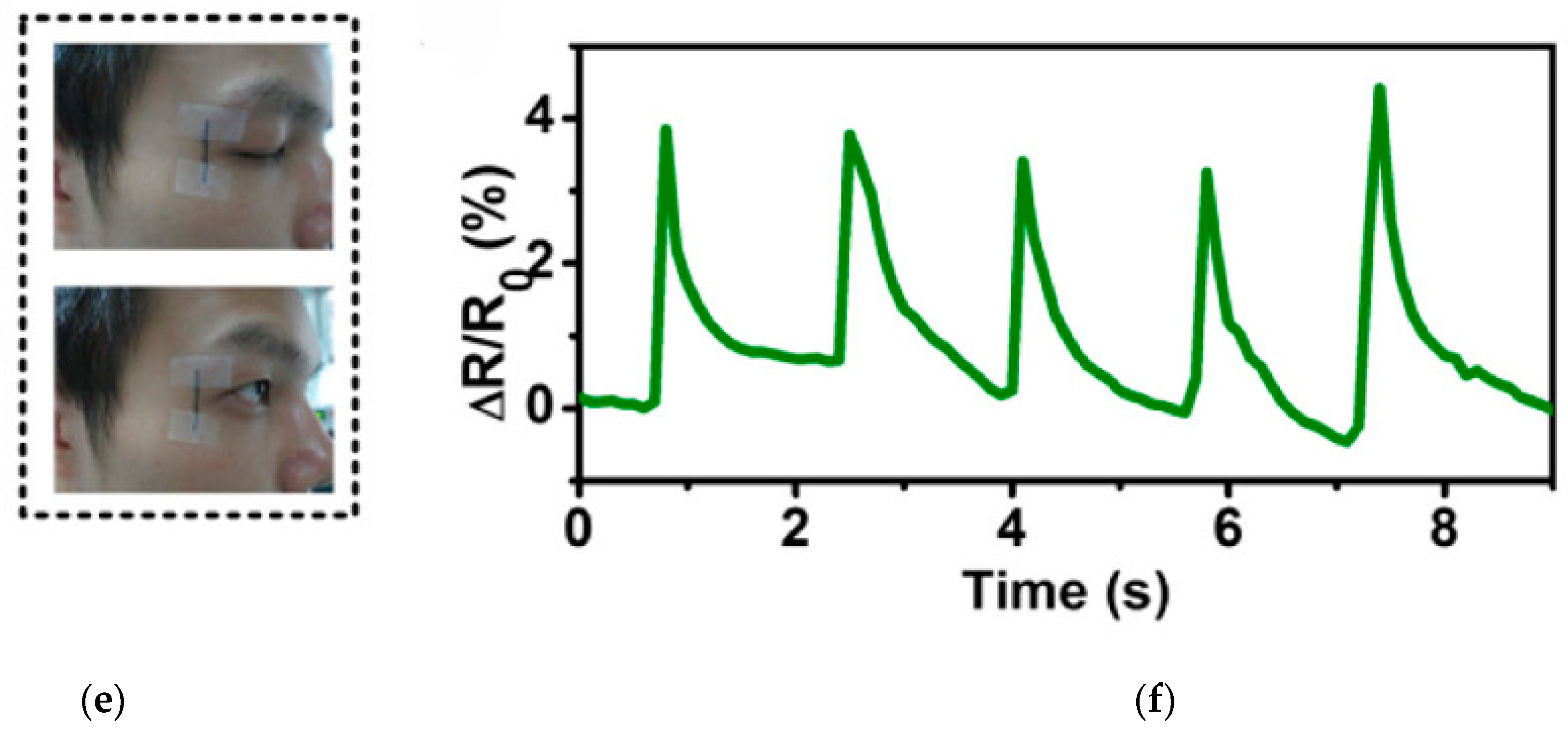
For small motion detection, the strain sensors necessarily have extremely high sensitivity. Otherwise, the electrical signals are not easily characterized to distinguish between the strains. For instance, a strain sensor is attached to the neck to detect the movement of the throat muscles. When people swallow something or say different words, different signals are recorded [95,106,123]. Strain sensors can detect complex epidermal/muscle movements by recording relative resistance changes, which have broad prospects in correcting standard pronunciation and expressing sounds of damaged vocal cords [124]. It is also possible to monitor facial expressions, such as crying, laughing, blinking and cheek bulging by installing flexible strain sensors on the cheeks, forehead or corners of the eyes (Figure 12e,f) [74]. Additionally, a high-performance strain sensor worn on the chest was used to track the breathing rate [96]. Flexible strain sensors were also implanted in the human bladder to monitor the size of the bladder to determine excretion [45,125].
In short, flexible fiber- and yarn-based strain sensors with excellent sensitivity have made significant progress in detecting human movement and activity information. They can be directly woven into clothes based on advanced textile machinery, which will facilitate low-cost and large-scale production. In addition, they can also be integrated with other one-dimensional flexible electronic devices, such as fiber-based batteries/supercapacitors, so as to realize miniaturized, portable wearable electronic products in the near future for potential medical care, rehabilitation and sports monitoring, etc.
5.2. Human–Computer Interaction
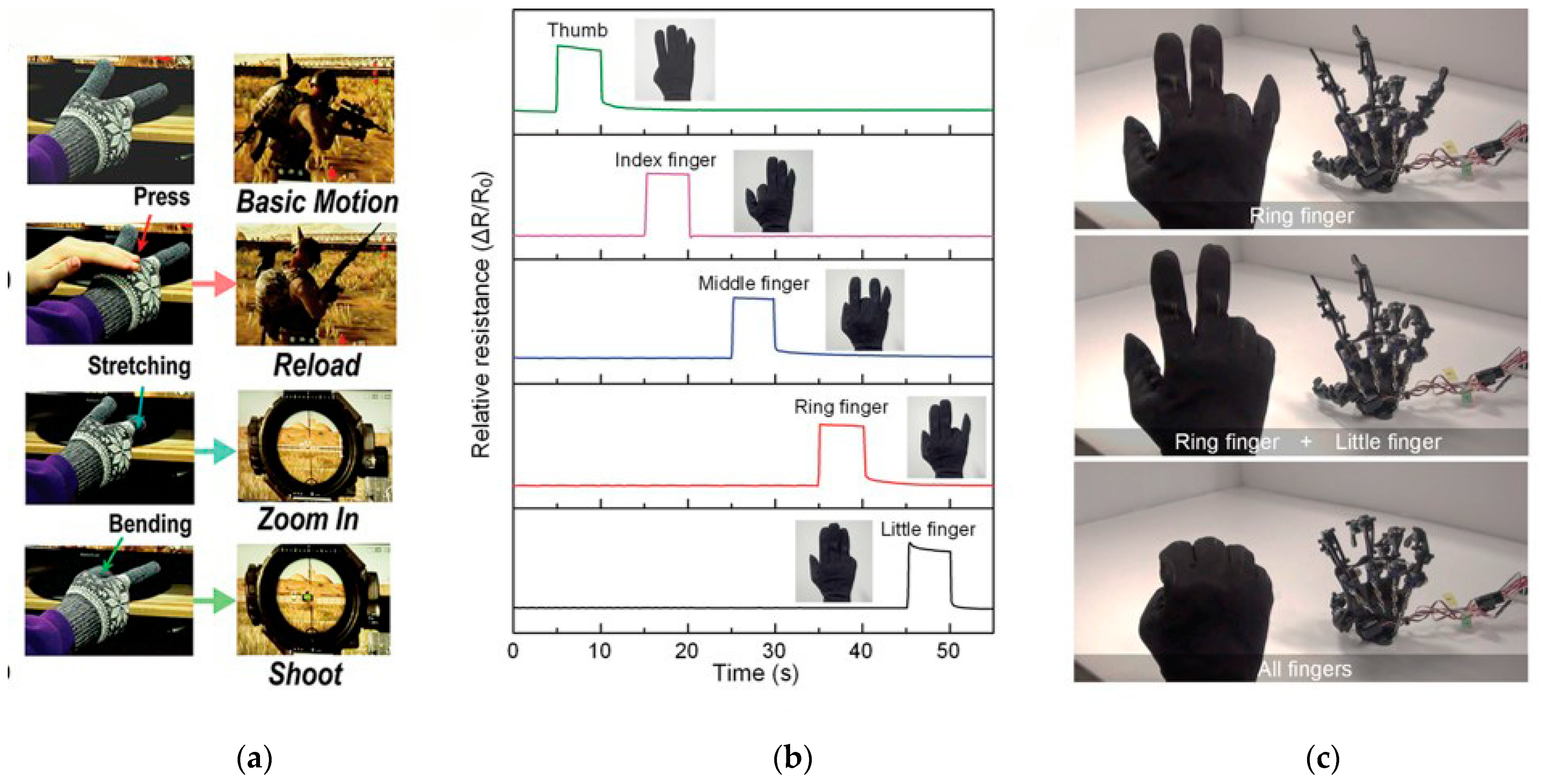
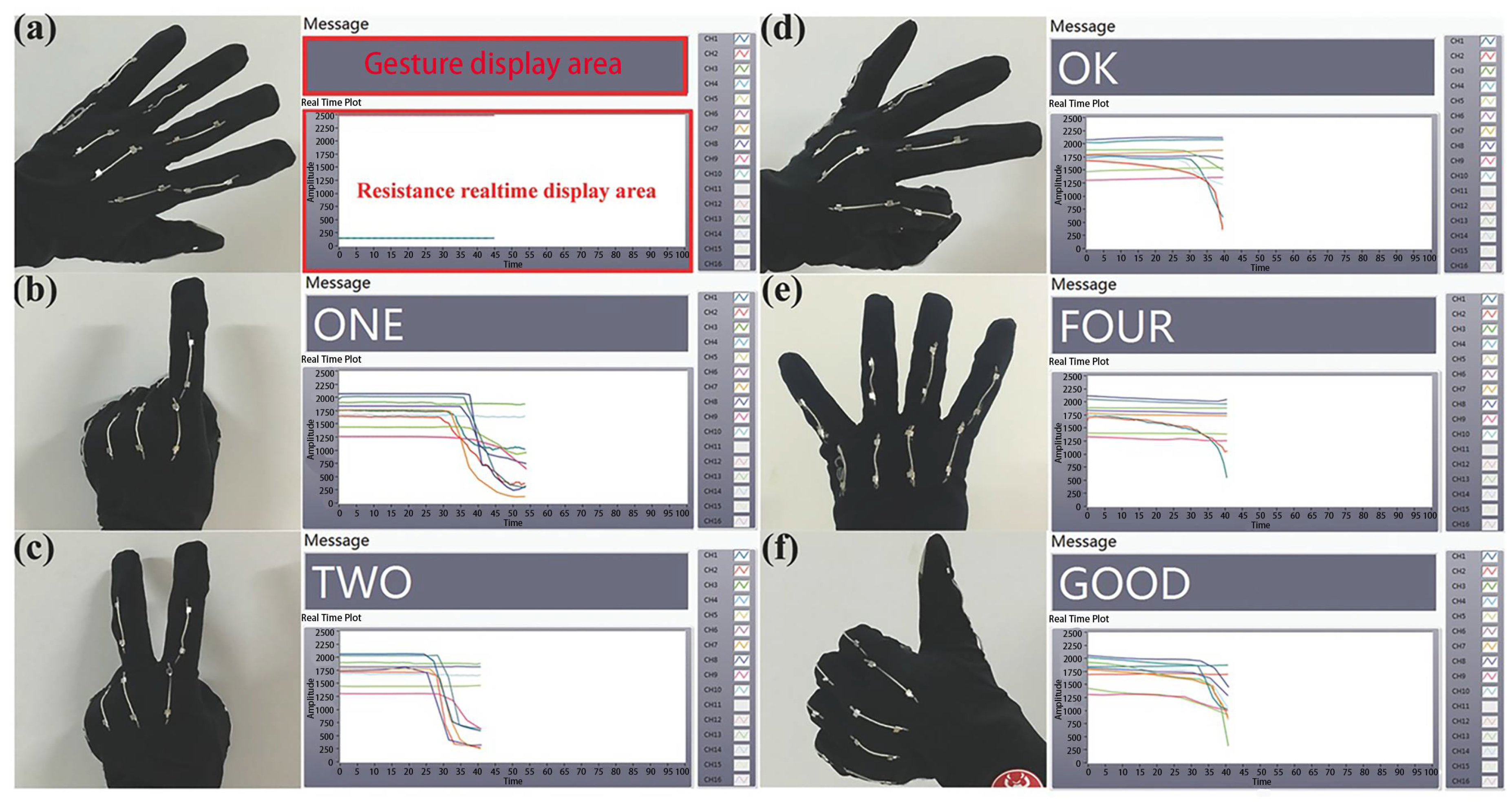
A data glove is a multimode virtual reality hardware that perform actions such as grabbing, moving and rotating objects in a virtual scene through software programming [125]. The emergence of the data glove provides a new interactive means for virtual reality systems. The product has been able to detect the bending of the finger and use the strain sensor to accurately locate the movement state of the hand. This kind of data glove combined with finger curvature test is called “real glove”, which can provide users with a very real and natural three-dimensional interactive means. In addition, the data glove can also be used as an auxiliary device for human or robot movement recognition and deaf–mute people. Fiber- or yarn-based strain sensors can not only detect various finger movements, but are also softs, light and knittable, and can be concealed in the glove without affecting its appearance. Choi et al. designed a conductive fiber sensor with a layered microsized hair-like structure, which exhibits excellent ductility (<200%) and sensitivity to various stimuli (pressure, stretching, and bending) [116]. They knit this kind of conductive fiber sensor into the glove and made a smart glove to detect the movement of the finger joints, so that the virtual interface was controlled by detecting the movement of the hand (Figure 13a). Lee et al. implanted AgNP-loaded spandex multifilament as a strain sensor on the nodes of the five fingers of the glove, which was used as a true wearable sensor platform in the human–machine interface (Figure 13b,c) [45]. Due to the high sensitivity of the fiber strain sensor, smart gloves easily monitor the real-time movement of each finger. Through the signal processing of the drive circuit and the microcontroller, the response of the strain sensor integrated into the finger of the smart glove is used to control the bending motion of the corresponding finger of the hand-shaped robot. Chen et al. prepared a high-stretch conductive yarn composed of Poly(vinylidenefluoride-co-trifluoroethylene) (P(VDF-TrFE)) polymer nanofibers mat and AgNW coated on the surface of elastic woven yarn, and then integrated ten conductive yarns into a wearable data glove [117]. Human gestures were recognized by detecting the movement of human fingers (Figure 14).
6. Conclusions and Outlook
In summary, this review summarized the recent developments in fiber- and yarn-based strain sensors, from commonly used conductive materials to common preparation methods (spinning and coating). The structural designs of strain sensors are introduced in detail, including internal structures (uniform, coaxial, porous, and hollow structures), surface microstructures (microcrack and wrinkled structures) and macrostructures (wrapped, braided, and winding structures). The internal structure design lowers the percolation threshold of materials, and the surface microstructure design improves the performance of the sensor. Each macrostructure has its own characteristics. In addition, the packaging and interconnection of strain sensors with other components are discussed. Finally, various potential practical applications of fiber- and yarn-based strain sensors are listed, such as health detection, biomedicine, data gloves, etc.
Although great progress has been made in the fabrication of strain sensors based on one-dimensional textile materials in recent years, there are still some problems that hinder their practical application. For example, strain sensors cannot have a high sensitivity, high stretchability, and high linearity at the same time. The crack mechanism or method of controlling conductive fillers near the percolation threshold can markedly improve the sensitivity of the materials, while they limit the working strain range of the sensor. The working strain range is not only related to the breaking strain of the elastic substrate, but also to the conductivity of the composite. The addition of conductive active materials by spinning or coating gives the textiles sufficient conductivity, but these treatments often reduce the breaking strain and elastic recovery rate of the composite. Furthermore, the hysteresis, repeatability, stability and durability of the sensor should be considered. At present, most of the current flexible strain sensors tend to use elastic polymers as the supporting substrate. However, the sensors inevitably present hysteresis, stress relaxation and creep phenomena due to the viscoelasticity of substrates. The interface between the conductive material and the supporting substrate will also affect the hysteresis and cycle stability of sensors. From a practical point of view, it is vital to study the interface between conductive materials and fiber ensembles.
The conductive sensing mechanisms of flexible fiber or yarn strain sensors are quite different from traditional semiconductor and metal sensors. For conductive composite fibers, the sensing mechanisms are mainly based on percolation theory [80,126] and tunnel theory [126,127]. Crack propagation is the main reason for the resistance variation of coating fiber sensors [118,128,129]. Geometric effects caused by changes in the structure or size of fibers or yarns will also affect the working effect of the sensor. The sensing mechanism is based on the contact resistances on different scales such as fibers and yarns [130]. These mechanisms allow us to understand the working mechanism of some flexible tensile strain sensors. However, for the “shoulder phenomenon” of existing strain sensors [64,81,131,132,133], there is still a lack of specific theoretical analyses to find the improvement methods for large hysteresis and unstable sensitivity. Therefore, it is meaningful to perfect the research on the controlling factors of the sensing performance of the fiber or yarn strain sensors. To fabricate the suitable working strain range and gauge factor of sensors, it is crucial to establish the relationship between yarn structure parameters and sensing performance.
At present, there are few reports of large-scale applications of flexible strain in the market, and the majority of reported fiber and yarn strain sensors are still in the laboratory study and development stage. It is also necessary to consider whether the sensor’s performance and life will be interfered with by the external environment. For example, the washability of the wearable electronic textiles needs to be considered because they may be dirty during use. However, due to the lack of an insulating layer or protective layer, most current fiber or yarn strain sensors are not washable. The conductive coating on the yarn may crack or peel off during washing [134,135]. Moreover, there are few studies on the washability and instability mechanism of strain sensors at present. Another unsolved problem is the ability to reliably integrate these sensors with different components. The connection of strain sensors to other devices through soldering, mechanical clamping, or functional adhesives may cause safety issues. Therefore, it is worth studying the effect of packaging technology on the performance while meeting the security and stability requirements of the interconnection.
Finally, to achieve truly comfortable portable wearable applications, comprehensive advances in electronics, software, and textile manufacturing are required. For instance, these wearable power supplies and circuits should ideally be flexible and stretchable so as to withstand the large strains applied to the fabrics during their normal use. It is worth considering a method to highly integrate electronics with clothing comfortably and aesthetically. Artificial intelligence is a key step in realizing sensor applications. As well as applications in human movement monitoring and human–machine interactions, other applications are yet to be developed. In summary, although great progress has been made in fiber- and yarn-based strain sensors have achieved in terms of materials, preparation methods, and structural design, there are still many problems and challenges to be solved before their commercial use.
Author Contributions
The authors contributed to this paper as follows: material review, writing of the paper, methodology, draft preparation, revisions and final manuscript preparation, F.H.; supervisory, draft review and editing, J.H. and X.Y. All authors have read and agreed to the published version of the manuscript.
Funding
This research was funded by Shanghai Natural Science Foundation (20ZR1400500) and the Fundamental Research Funds for the Central Universities (2232021G-01).
Institutional Review Board Statement
Not applicable.
Informed Consent Statement
Not applicable.
Data Availability Statement
Not applicable.
Acknowledgments
Thank you to the supervisory team.
Conflicts of Interest
The authors declare no conflict of interest.
References
- Wu, Y.T.; Yan, T.; Pan, Z.J. Wearable carbon-based resistive sensors for strain detection: A review. IEEE Sens. J. 2020, 21, 4030–4041. [Google Scholar] [CrossRef]
- Zheng, M.Y.; Li, W.Y.; Xu, M.J.; Xu, N.; Chen, P.; Han, M.; Xie, B. Strain sensors based on chromium nanoparticle arrays. Nanoscale 2014, 6, 3930–3933. [Google Scholar] [CrossRef]
- Barlian, A.A.; Park, W.T.; Mallon, J.R.; Rastegar, A.J.; Pruitt, B.L. Review: Semiconductor piezoresistance for microsystems. Proc IEEE Inst. Electr. Electron Eng. 2009, 97, 513–552. [Google Scholar] [CrossRef] [Green Version]
- Wang, T.; Ouyang, Z.; Wang, F.; Liu, Y. A review on graphene strain sensors based on fiber assemblies. SN Appl. Sci. 2020, 2, 862. [Google Scholar] [CrossRef] [Green Version]
- Wang, B.; Facchetti, A. Mechanically flexible conductors for stretchable and wearable E-skin and E-textile devices. Adv. Mater. 2019, 31, 1901408. [Google Scholar] [CrossRef]
- Lee, J.; Zambrano, B.L.; Woo, J.; Yoon, K.; Lee, T. Recent advances in 1D stretchable electrodes and devices for textile and wearable electronics: Materials, fabrications, and applications. Adv. Mater. 2020, 32, 1902532. [Google Scholar] [CrossRef] [PubMed] [Green Version]
- Zhao, Y.N.; Huang, Y.; Hu, W.; Guo, X.H.; Wang, Y.; Liu, P.; Liu, C.X.; Zhang, Y.G. Highly sensitive flexible strain sensor based on threadlike spandex substrate coating with conductive nanocomposites for wearable electronic skin. Smart Mater. Struct. 2019, 28, 035004. [Google Scholar] [CrossRef]
- Quan, Y.N.; Hu, J.Y.; Yang, X.D.; Lu, Z. Preparation and characterization of resistive strain sensor based on braided skin-core rope. J. Donghua Univ. 2019, 36, 458–465. [Google Scholar]
- Dong, X.L.; Wang, T.T.; Hu, J.Y.; Dong, H.Q.; Lu, Z.; Yang, X.D. Effect of dip coating process on the performance of graphene/spandex yarn strain sensor. J. Donghua Univ. 2019, 36, 451–457. [Google Scholar]
- Wang, X.; Sparkman, J.; Gou, J.H. Strain sensing of printed carbon nanotube sensors on polyurethane substrate with spray deposition modeling. Compos. Commun. 2017, 3, 1–6. [Google Scholar] [CrossRef]
- Yu, Y.; Luo, Y.F.; Guo, A.; Yan, L.J.; Wu, Y.; Jiang, K.L.; Li, Q.Q.; Fan, S.S.; Wang, J.P. Flexible and transparent strain sensors based on super-aligned carbon nanotube films. Nanoscale 2017, 9, 6716–6723. [Google Scholar] [CrossRef] [PubMed]
- Amjadi, M.; Turan, M.; Clementson, C.P.; Sitti, M. Parallel microcracks-based ultrasensitive and highly stretchable strain sensors. ACS Appl. Mater. Interfaces 2016, 8, 5618–5626. [Google Scholar] [CrossRef] [PubMed]
- Wang, Y.L.; Hao, J.; Huang, Z.Q.; Zheng, G.Q.; Dai, K.; Liu, C.T.; Shen, C.Y. Flexible electrically resistive-type strain sensors based on reduced graphene oxide-decorated electrospun polymer fibrous mats for human motion monitoring. Carbon 2018, 126, 360–371. [Google Scholar] [CrossRef]
- Lin, L.; Wang, L.; Li, B.; Luo, J.; Huang, X.; Gao, Q.; Xue, H.; Gao, J. Dual conductive network enabled superhydrophobic and high performance strain sensors with outstanding electro-thermal performance and extremely high gauge factors. Chem. Eng. J. 2020, 385, 123391. [Google Scholar] [CrossRef]
- Seyedin, S.; Zhang, P.; Naebe, M.; Qin, S.; Chen, J.; Wang, X.A.; Razal, J.M. Textile strain sensors: A review of the fabrication technologies, performance evaluation and applications. Mater. Horiz. 2019, 6, 219–249. [Google Scholar] [CrossRef]
- Luo, J.C.; Gao, S.J.; Luo, H.; Wang, L.; Huang, X.W.; Guo, Z.; Lai, X.J.; Lin, L.W.; Li, R.K.Y.; Gao, J.F. Superhydrophobic and breathable smart MXene-based textile for multifunctional wearable sensing electronics. Chem. Eng. J. 2021, 406, 126898. [Google Scholar] [CrossRef]
- Hu, J.; Zhou, S.; Shi, J.; Zhang, H.; Zhu, F.; Yang, X. Determinants of electrical resistance change of in situ PPy-polymerized stretch plain woven fabric under uniaxial tensile strain. J. Text. Inst. 2017, 108, 1545–1551. [Google Scholar] [CrossRef]
- Jiyong, H.; Xiaofeng, Z.; Guohao, L.; Xudong, Y.; Xin, D. Electrical properties of PPy-coated conductive fabrics for human joint motion monitoring. Nephron Clin. Pract. 2016, 16, 7–12. [Google Scholar] [CrossRef] [Green Version]
- Wang, L.; Zhang, M.; Yang, B.; Tan, J.; Ding, X. Highly compressible, thermally stable, light-weight, and robust aramid nanofibers/Ti3AlC2 MXene composite aerogel for sensitive pressure sensor. ACS Nano 2020, 14, 10633–10647. [Google Scholar] [CrossRef]
- Bi, L.; Yang, Z.; Chen, L.; Wu, Z.; Ye, C. Compressible AgNWs/Ti3C2Tx MXene aerogel-based highly sensitive piezoresistive pressure sensor as versatile electronic skins. J. Mater. Chem. A 2020, 8, 20030–20036. [Google Scholar] [CrossRef]
- Cao, X.; Zhang, J.; Chen, S.; Varley, R.J.; Pan, K. 1D/2D nanomaterials synergistic, compressible, and response rapidly 3D graphene aerogel for piezoresistive sensor. Adv. Funct. Mater. 2020, 30, 2003618. [Google Scholar] [CrossRef]
- Wei, X.D.; Cao, X.H.; Wang, Y.L.; Zheng, G.Q.; Dai, K.; Liu, C.T.; Shen, C.Y. Conductive herringbone structure carbon nanotube/thermoplastic polyurethane porous foam tuned by epoxy for high performance flexible piezoresistive sensor. Compos. Sci. Technol. 2017, 149, 166–177. [Google Scholar] [CrossRef]
- Li, Q.; Li, J.; Tran, D.Q.; Luo, C.Q.; Gao, Y.; Yu, C.J.; Xuan, F.Z. Engineering of carbon nanotube/polydimethylsiloxane nanocomposites with enhanced sensitivity for wearable motion sensors. J. Mater. Chem. C 2017, 5, 11092–11099. [Google Scholar] [CrossRef]
- Geng, W.H.Y.; Cuthbert, T.J.; Menon, C. Conductive thermoplastic elastomer composite capacitive strain sensors and their application in a wearable device for quantitative joint angle prediction. ACS Appl. Polym. 2021, 3, 122–129. [Google Scholar] [CrossRef]
- Choi, C.; Lee, J.M.; Kim, S.H.; Kim, S.J.; Di, J.T.; Baughman, R.H. Twistable and stretchable sandwich structured fiber for wearable sensors and supercapacitors. Nano Lett. 2016, 16, 7677–7684. [Google Scholar] [CrossRef] [PubMed]
- Atalay, A.; Sanchez, V.; Atalay, O.; Vogt, D.M.; Haufe, F.; Wood, R.J.; Walsh, C.J. Batch fabrication of customizable silicone-textile composite capacitive strain sensors for human motion tracking. Adv. Mater. Technol. 2017, 2, 1700136. [Google Scholar] [CrossRef] [Green Version]
- Cooper, C.B.; Arutselvan, K.; Liu, Y.; Armstrong, D.; Lin, Y.L.; Khan, M.R.; Genzer, J.; Dickey, M.D. Stretchable capacitive sensors of torsion, strain, and touch using double helix liquid metal fibers. Adv. Funct. Mater. 2017, 27, 1605630. [Google Scholar] [CrossRef]
- Chen, H. Application of precipitate free zone growth kinetics to the beta-phase depletion behavior in a CoNiCrAlY coating alloy: An analytical approach. Metall. Mater Trans. A 2018, 49A, 2551–2560. [Google Scholar] [CrossRef]
- Persano, L.; Dagdeviren, C.; Su, Y.W.; Zhang, Y.H.; Girardo, S.; Pisignano, D.; Huang, Y.G.; Rogers, J.A. High performance piezoelectric devices based on aligned arrays of nanofibers of poly(vinylidenefluoride-co-trifluoroethylene). Nat. Commun. 2013, 4, 1633. [Google Scholar] [CrossRef]
- Wu, R.; Ma, L.; Liu, S.; Patil, A.B.; Hou, C.; Zhang, Y.; Zhang, W.; Yu, R.; Yu, W.; Guo, W.; et al. Fibrous inductance strain sensors for passive inductance textile sensing. Mater. Today Phys. 2020, 15, 100243. [Google Scholar] [CrossRef]
- Xing, Z.G.; Lin, J.; McCoul, D.; Zhang, D.P.; Zhao, J.W. Inductive strain sensor with high repeatability and ultra-low hysteresis based on mechanical spring. IEEE Sens. J. 2020, 20, 14670–14675. [Google Scholar] [CrossRef]
- Chen, J.; Zhu, G.; Yang, W.Q.; Jing, Q.S.; Bai, P.; Yang, Y.; Hou, T.C.; Wang, Z.L. Harmonic-resonator-based triboelectric nanogenerator as a sustainable power source and a self-powered active vibration sensor. Adv. Mater. 2013, 25, 6094–6099. [Google Scholar] [CrossRef]
- Hsieh, H.H.; Hsu, F.C.; Chen, Y.F. Energetically autonomous, wearable, and multifunctional sensor. ACS Sens. 2018, 3, 113–120. [Google Scholar] [CrossRef] [PubMed] [Green Version]
- Wu, X.; Han, Y.; Zhang, X.; Lu, C. Highly sensitive, stretchable, and wash-durable strain sensor based on ultrathin conductive layer@polyurethane yarn for tiny motion monitoring. ACS Appl. Mater. Interfaces 2016, 8, 9936–9945. [Google Scholar] [CrossRef] [PubMed]
- Pan, J.J.; Hao, B.W.; Song, W.F.; Chen, S.X.; Li, D.Q.; Luo, L.; Xia, Z.G.; Cheng, D.S.; Xu, A.C.; Cai, G.M.; et al. Highly sensitive and durable wearable strain sensors from a core-sheath nanocomposite yarn. Compos. B Eng. 2020, 183, 107683. [Google Scholar] [CrossRef]
- Eom, J.; Jaisutti, R.; Lee, H.; Lee, W.; Heo, J.S.; Lee, J.Y.; Park, S.K.; Kim, Y.H. Highly sensitive textile strain sensors and wireless user-interface devices using all-polymeric conducting fibers. ACS Appl. Mater. Interfaces 2017, 9, 10190–10197. [Google Scholar] [CrossRef]
- Yue, X.; Jia, Y.; Wang, X.; Zhou, K.; Zhai, W.; Zheng, G.; Dai, K.; Mi, L.; Liu, C.; Shen, C. Highly stretchable and durable fiber-shaped strain sensor with porous core-sheath structure for human motion monitoring. Compos. Sci. Technol. 2020, 189, 108038. [Google Scholar] [CrossRef]
- Zhou, J.; Xu, X.Z.; Xin, Y.Y.; Lubineau, G. Coaxial thermoplastic elastomer-wrapped carbon nanotube fibers for deformable and wearable strain sensors. Adv. Funct. Mater. 2018, 28, 1705591. [Google Scholar] [CrossRef]
- Wang, X.; Sun, H.; Yue, X.; Yu, Y.; Zheng, G.; Dai, K.; Liu, C.; Shen, C. A highly stretchable carbon nanotubes/thermoplastic polyurethane fiber-shaped strain sensor with porous structure for human motion monitoring. Compos. Sci. Technol. 2018, 168, 126–132. [Google Scholar] [CrossRef]
- Li, Y.H.; Zhou, B.; Zheng, G.Q.; Liu, X.H.; Li, T.X.; Yan, C.; Cheng, C.B.; Dai, K.; Liu, C.T.; Shen, C.Y.; et al. Continuously prepared highly conductive and stretchable SWNT/MWNT synergistically composited electrospun thermoplastic polyurethane yarns for wearable sensing. J. Mater. Chem. C 2018, 6, 2258–2269. [Google Scholar] [CrossRef]
- Zhang, M.; Wang, C.; Wang, Q.; Jian, M.; Zhang, Y. Sheath-core graphite/silk fiber made by dry-meyer-rod-coating for wearable strain sensors. ACS Appl. Mater. Interfaces 2016, 8, 20894–20899. [Google Scholar] [CrossRef]
- Li, X.T.; Koh, K.H.; Farhan, M.; Lai, K.W.C. An ultraflexible polyurethane yarn-based wearable strain sensor with a polydimethylsiloxane infiltrated multilayer sheath for smart textiles. Nanoscale 2020, 12, 4110–4118. [Google Scholar] [CrossRef] [PubMed]
- Lu, Y.; Jiang, J.W.; Yoon, S.; Kim, K.S.; Kim, J.H.; Park, S.; Kim, S.H.; Piao, L.H. High-performance stretchable conductive composite fibers from surface-modified silver nanowires and thermoplastic polyurethane by wet spinning. ACS Appl. Mater. Interfaces 2018, 10, 2093–2104. [Google Scholar] [CrossRef] [PubMed]
- Ma, R.; Kang, B.; Cho, S.; Choi, M.; Baik, S. Extraordinarily high conductivity of stretchable fibers of polyurethane and silver nanoflowers. ACS Nano 2015, 9, 10876–10886. [Google Scholar] [CrossRef] [PubMed]
- Lee, J.; Shin, S.; Lee, S.; Song, J.; Kang, S.; Han, H.; Kim, S.; Kim, S.; Seo, J.; Kim, D.; et al. Highly sensitive multifilament fiber strain sensors with ultrabroad sensing range for textile electronics. ACS Nano 2018, 12, 4259–4268. [Google Scholar] [CrossRef] [PubMed]
- Zhu, C.; Li, R.; Chen, X.; Chalmers, E.; Liu, X.; Wang, Y.; Xu, B.B.; Liu, X. Ultraelastic yarns from curcumin-assisted ELD toward wearable human-machine interface textiles. Adv. Sci. 2020, 7, 2002009. [Google Scholar] [CrossRef] [PubMed]
- Zhao, S.F.; Han, F.; Li, J.H.; Meng, X.Y.; Huang, W.P.; Cao, D.X.; Zhang, G.P.; Sun, R.; Wong, C.P. Advancements in copper nanowires: Synthesis, purification, assemblies, surface modification, and applications. Small 2018, 14, 1800047. [Google Scholar] [CrossRef]
- Zhu, S.; So, J.H.; Mays, R.; Desai, S.; Barnes, W.R.; Pourdeyhimi, B.; Dickey, M.D. Ultrastretchable fibers with metallic conductivity using a liquid metal alloy core. Adv. Funct. Mater. 2013, 23, 2308–2314. [Google Scholar] [CrossRef]
- Ahmed, A.; Hossain, M.M.; Adak, B.; Mukhopadhyay, S. Recent advances in 2D MXene integrated smart-textile interfaces for multifunctional applications. Chem. Mat. 2020, 32, 10296–10320. [Google Scholar] [CrossRef]
- Huang, Y.; Ellingford, C.; Bowen, C.; McNally, T.; Wu, D.; Wan, C. Tailoring the electrical and thermal conductivity of multi-component and multi-phase polymer composites. Int. Mater. Rev. 2019, 65, 129–163. [Google Scholar] [CrossRef]
- Tseghai, G.B.; Mengistie, D.A.; Malengier, B.; Fante, K.A.; Van Langenhove, L. PEDOT:PSS-based conductive textiles and their applications. Sensors 2020, 20, 1881. [Google Scholar] [CrossRef] [Green Version]
- Qi, G.J.; Huang, L.Y.; Wang, H.L. Highly conductive free standing polypyrrole films prepared by freezing interfacial polymerization. Chem. Commun. 2012, 48, 8246–8248. [Google Scholar] [CrossRef] [PubMed]
- Worfolk, B.J.; Andrews, S.C.; Park, S.; Reinspach, J.; Liu, N.; Toney, M.F.; Mannsfeld, S.C.B.; Bao, Z.N. Ultrahigh electrical conductivity in solution-sheared polymeric transparent films. Proc. Natl. Acad. Sci. USA 2015, 112, 14138–14143. [Google Scholar] [CrossRef] [PubMed] [Green Version]
- Li, X.K.; Li, M.J.; Zong, L.; Wu, X.C.; You, J.; Du, P.K.; Li, C.X. Liquid metal droplets wrapped with polysaccharide microgel as biocompatible aqueous ink for flexible conductive devices. Adv. Funct. Mater. 2018, 28, 1804197. [Google Scholar] [CrossRef]
- Pan, Z.Y.; Ma, J.Z.; Zhang, W.B.; Wei, L.F. Flexible conductive polymer composites in strain sensors. Prog. Chem. 2020, 32, 1592–1607. [Google Scholar]
- Seyedin, M.Z.; Razal, J.M.; Innis, P.C.; Wallace, G.G. Strain-responsive polyurethane/PEDOT:PSS elastomeric composite fibers with high electrical conductivity. Adv. Funct. Mater. 2014, 24, 2957–2966. [Google Scholar] [CrossRef] [Green Version]
- Meer, S.; Kausar, A.; Iqbal, T. Trends in conducting polymer and hybrids of conducting polymer/carbon nanotube: A review. Polym. Plast. Technol. Eng. 2016, 55, 1416–1440. [Google Scholar] [CrossRef]
- Li, L.; Shi, P.; Hua, L.; An, J.; Gong, Y.; Chen, R.; Yu, C.; Hua, W.; Xiu, F.; Zhou, J.; et al. Design of a wearable and shape-memory fibriform sensor for the detection of multimodal deformation. Nanoscale 2017, 10, 118–123. [Google Scholar] [CrossRef]
- Wu, H.; Liu, Q.; Chen, H.; Shi, G.; Li, C. Fibrous strain sensor with ultra-sensitivity, wide sensing range, and large linearity for full-range detection of human motion. Nanoscale 2018, 10, 17512–17519. [Google Scholar] [CrossRef]
- Seyedin, S.; Razal, J.M.; Innis, P.C.; Wallace, G.G. A facile approach to spinning multifunctional conductive elastomer fibres with nanocarbon fillers. Smart Mater. Struct. 2016, 25, 035015. [Google Scholar] [CrossRef]
- Zhang, R.; Pan, P.; Dai, Q.; Yang, X.; Yang, Z.; Wei, J.; Liu, J.; Yuan, Q. Sensitive and wearable carbon nanotubes/carbon black strain sensors with wide linear ranges for human motion monitoring. J. Mater. Sci. Mater. Electron. 2018, 29, 5589–5596. [Google Scholar] [CrossRef]
- Zhang, W.Y.; Liu, Q.; Chen, P. Flexible strain sensor based on carbon black/silver nanoparticles composite for human motion detection. Materials 2018, 11, 1836. [Google Scholar] [CrossRef] [Green Version]
- Zheng, Y.; Li, Y.; Dai, K.; Liu, M.; Zhou, K.; Zheng, G.; Liu, C.; Shen, C. Conductive thermoplastic polyurethane composites with tunable piezoresistivity by modulating the filler dimensionality for flexible strain sensors. Compos. Part A Appl. Sci. Manuf. 2017, 101, 41–49. [Google Scholar] [CrossRef]
- Zheng, Y.J.; Li, Y.L.; Li, Z.Y.; Wang, Y.L.; Dai, K.; Zheng, G.Q.; Liu, C.T.; Shen, C.Y. The effect of filler dimensionality on the electromechanical performance of polydimethylsiloxane based conductive nanocomposites for flexible strain sensors. Compos. Sci. Technol. 2017, 139, 64–73. [Google Scholar] [CrossRef]
- Heo, J.S.; Hossain, M.F.; Kim, I. Challenges in design and fabrication of flexible/stretchable carbon- and textile-based wearable sensors for health monitoring: A critical review. Sensors 2020, 20, 3927. [Google Scholar] [CrossRef] [PubMed]
- Yan, T.; Wang, Z.; Pan, Z.-J. Flexible strain sensors fabricated using carbon-based nanomaterials: A review. Curr. Opin. Solid State Mater. Sci. 2018, 22, 213–228. [Google Scholar] [CrossRef]
- Ojstrsek, A.; Plohl, O.; Gorgieva, S.; Kurecic, M.; Jancic, U.; Hribernik, S.; Fakin, D. Metallisation of textiles and protection of conductive layers: An overview of application techniques. Sensors 2021, 21, 3508. [Google Scholar] [CrossRef]
- Qin, R.; Shan, G.; Hu, M.; Huang, W. Two-dimensional transition metal carbides and/or nitrides (MXenes) and their applications in sensors. Mater. Today Phys. 2021, 21, 100527. [Google Scholar] [CrossRef]
- Gong, M.; Yue, L.C.; Kong, J.Y.; Lin, X.; Zhang, L.; Wang, J.P.; Wang, D.R. Knittable and sewable spandex yarn with nacre-mimetic composite coating for wearable health monitoring and thermo- and antibacterial therapies. ACS Appl. Mater. Interfaces 2021, 13, 9053–9063. [Google Scholar] [CrossRef]
- Li, W.Y.; Zhou, Y.F.; Wang, Y.H.; Li, Y.; Jiang, L.; Ma, J.W.; Chen, S.J. Highly stretchable and sensitive SBS/graphene composite fiber for strain sensors. Macromol. Mater. Eng. 2020, 305, 1900736. [Google Scholar] [CrossRef]
- He, Z.; Zhou, G.; Byun, J.H.; Lee, S.K.; Um, M.K.; Park, B.; Kim, T.; Lee, S.B.; Chou, T.W. Highly stretchable multi-walled carbon nanotube/thermoplastic polyurethane composite fibers for ultrasensitive, wearable strain sensors. Nanoscale 2019, 11, 5884–5890. [Google Scholar] [CrossRef] [PubMed]
- He, Z.; Byun, J.H.; Zhou, G.; Park, B.J.; Kim, T.H.; Lee, S.B.; Yi, J.W.; Um, M.K.; Chou, T.W. Effect of MWCNT content on the mechanical and strain-sensing performance of thermoplastic polyurethane composite fibers. Carbon 2019, 146, 701–708. [Google Scholar] [CrossRef]
- Zhang, S.; He, Z.; Zhou, G.; Jung, B.-M.; Kim, T.-H.; Park, B.-J.; Byun, J.-H.; Chou, T.-W. High conductive free-written thermoplastic polyurethane composite fibers utilized as weight-strain sensors. Compos. Sci. Technol. 2020, 189, 108011. [Google Scholar] [CrossRef]
- Tang, Z.; Jia, S.; Wang, F.; Bian, C.; Chen, Y.; Wang, Y.; Li, B. Highly stretchable core-sheath fibers via wet-spinning for wearable strain sensors. ACS Appl. Mater. Interfaces 2018, 10, 6624–6635. [Google Scholar] [CrossRef] [PubMed]
- Seyedin, S.; Uzun, S.; Levitt, A.; Anasori, B.; Dion, G.; Gogotsi, Y.; Razal, J.M. MXene composite and coaxial fibers with high stretchability and conductivity for wearable strain sensing textiles. Adv. Funct. Mater. 2020, 30, 1910504. [Google Scholar] [CrossRef]
- Gao, J.C.; Wang, X.Z.; Zhai, W.; Liu, H.; Zheng, G.Q.; Dai, K.; Mi, L.W.; Liu, C.T.; Shen, C.Y. Ultrastretchable multilayered fiber with a hollow-monolith structure for high-performance strain sensor. ACS Appl. Mater. Interfaces 2018, 10, 34592–34603. [Google Scholar] [CrossRef]
- Marsden, A.J.; Papageorgiou, D.G.; Valles, C.; Liscio, A.; Palermo, V.; Bissett, M.A.; Young, R.J.; Kinloch, I.A. Electrical percolation in graphene-polymer composites. 2D Mater. 2018, 5, 032003. [Google Scholar] [CrossRef] [Green Version]
- Zhang, H.B.; Zheng, W.G.; Yan, Q.; Yang, Y.; Wang, J.W.; Lu, Z.H.; Ji, G.Y.; Yu, Z.Z. Electrically conductive polyethylene terephthalate/graphene nanocomposites prepared by melt compounding. Polymer 2010, 51, 1191–1196. [Google Scholar] [CrossRef]
- Babinec, S.J.; Mussell, R.D.; Lundgard, R.L.; Cieslinski, R. Electroactive thermoplastics. Adv. Mater. 2000, 12, 1823–1834. [Google Scholar] [CrossRef]
- Janssen, H.K.; Tauber, U.C. The field theory approach to percolation processes. Ann. Phys. 2005, 315, 147–192. [Google Scholar] [CrossRef] [Green Version]
- Liu, H.; Li, Y.L.; Dai, K.; Zheng, G.Q.; Liu, C.T.; Shen, C.Y.; Yan, X.R.; Guo, J.; Guo, Z.H. Electrically conductive thermoplastic elastomer nanocomposites at ultralow graphene loading levels for strain sensor applications. J. Mater. Chem. C 2016, 4, 157–166. [Google Scholar] [CrossRef]
- Balberg, I. Tunneling and nonuniversal conductivity in composite-materials. Phys. Rev. Lett. 1987, 59, 1305–1308. [Google Scholar] [CrossRef]
- Pang, H.; Xu, L.; Yan, D.X.; Li, Z.M. Conductive polymer composites with segregated structures. Prog. Polym. Sci. 2014, 39, 1908–1933. [Google Scholar] [CrossRef]
- Xu, Y.T.; Wang, Y.; Zhou, C.G.; Sun, W.J.; Dai, K.; Tang, J.H.; Lei, J.; Yan, D.X.; Li, Z.M. An electrically conductive polymer composite with a co-continuous segregated structure for enhanced mechanical performance. J. Mater. Chem. C 2020, 8, 11546–11554. [Google Scholar] [CrossRef]
- Zhang, X.W.; Pan, Y.; Zheng, Q.; Yi, X.S. Time dependence of piezoresistance for the conductor-filled polymer composites. J Polym. Sci. B Polym. Phys. 2000, 38, 2739–2749. [Google Scholar] [CrossRef]
- Granero, A.J.; Wagner, P.; Wagner, K.; Razal, J.M.; Wallace, G.G.; in het Panhuis, M. Highly stretchable conducting SIBS-P3HT fibers. Adv. Funct. Mater. 2011, 21, 955–962. [Google Scholar] [CrossRef]
- Ren, M.N.; Zhou, Y.J.; Wang, Y.; Zheng, G.Q.; Dai, K.; Liu, C.T.; Shen, C.Y. Highly stretchable and durable strain sensor based on carbon nanotubes decorated thermoplastic polyurethane fibrous network with aligned wavelike structure. Chem. Eng. J. 2019, 360, 762–777. [Google Scholar] [CrossRef]
- Liu, Z.; Qi, D.; Hu, G.; Wang, H.; Jiang, Y.; Chen, G.; Luo, Y.; Loh, X.J.; Liedberg, B.; Chen, X. Surface strain redistribution on structured microfibers to enhance sensitivity of fiber-shaped stretchable strain sensors. Adv. Mater. 2018, 30, 1704229. [Google Scholar] [CrossRef] [PubMed]
- Wang, R.; Jiang, N.; Su, J.; Yin, Q.; Zhang, Y.; Liu, Z.; Lin, H.; Moura, F.A.; Yuan, N.; Roth, S.; et al. A bi-sheath fiber sensor for giant tensile and torsional displacements. Adv. Funct. Mater. 2017, 27, 1702134. [Google Scholar] [CrossRef]
- Sun, H.; Dai, K.; Zhai, W.; Zhou, Y.; Li, J.; Zheng, G.; Li, B.; Liu, C.; Shen, C. A highly sensitive and stretchable yarn strain sensor for human motion tracking utilizing a wrinkle-assisted crack structure. ACS Appl. Mater. Interfaces 2019, 11, 36052–36062. [Google Scholar] [CrossRef]
- Cao, Z.R.; Wang, R.R.; He, T.Y.; Xu, F.F.; Sun, J. Interface-controlled conductive fibers for wearable strain sensors and stretchable conducting Wires. ACS Appl. Mater. Interfaces 2018, 10, 14087–14096. [Google Scholar] [CrossRef]
- Liu, H.; Zhu, L.L.; He, Y.; Cheng, B.W. A novel method for fabricating elastic conductive polyurethane filaments by in-situ reduction of polydopamine and electroless silver plating. Mater. Design 2017, 113, 254–263. [Google Scholar] [CrossRef]
- Fu, L.; Yu, A.M. Carbon nanotubes based thin films: Fabrication, characterization and applications. Rev. Adv. Mater. Sci. 2014, 36, 40–61. [Google Scholar]
- Li, X.; Hua, T.; Xu, B. Electromechanical properties of a yarn strain sensor with graphene-sheath/polyurethane-core. Carbon 2017, 118, 686–698. [Google Scholar] [CrossRef]
- Cai, G.; Hao, B.; Luo, L.; Deng, Z.; Zhang, R.; Ran, J.; Tang, X.; Cheng, D.; Bi, S.; Wang, X.; et al. Highly stretchable sheath-core yarns for multifunctional wearable electronics. ACS Appl. Mater. Interfaces 2020, 12, 29717–29727. [Google Scholar] [CrossRef]
- Cheng, Y.; Wang, R.; Sun, J.; Gao, L. A stretchable and highly sensitive graphene-based fiber for sensing tensile strain, bending, and torsion. Adv. Mater. 2015, 27, 7365–7371. [Google Scholar] [CrossRef]
- Shi, B.; Wang, T.; Shi, L.; Li, J.; Wang, R.; Sun, J. Highly stretchable and strain sensitive fibers based on braid-like structure and sliver nanowires. Appl. Mater. Today 2020, 19, 100610. [Google Scholar] [CrossRef]
- Yang, Z.; Wang, W.; Bi, L.; Chen, L.; Wang, G.; Chen, G.; Ye, C.; Pan, J. Wearable electronics for heating and sensing based on a multifunctional PET/silver nanowire/PDMS yarn. Nanoscale 2020, 12, 16562–16569. [Google Scholar] [CrossRef]
- Gao, Y.; Guo, F.Y.; Cao, P.; Liu, J.C.; Li, D.M.; Wu, J.; Wang, N.; Su, Y.W.; Zhao, Y. Winding-locked carbon nanotubes/polymer nanofibers helical yarn for ultrastretchable conductor and strain sensor. ACS Nano 2020, 14, 3442–3450. [Google Scholar] [CrossRef]
- Xie, X.X.; Huang, H.; Zhu, J.; Yu, J.R.; Wang, Y.; Hu, Z.M. A spirally layered carbon nanotube-graphene/polyurethane composite yarn for highly sensitive and stretchable strain sensor. Compos. Part A Appl. Sci. Manuf. 2020, 135, 105932. [Google Scholar] [CrossRef]
- de Mulatier, S.; Nasreldin, M.; Delattre, R.; Ramuz, M.; Djenizian, T. Electronic circuits integration in textiles for data processing in wearable technologies. Adv. Mater. Technol. 2018, 3, 1700320. [Google Scholar] [CrossRef]
- Simegnaw, A.A.; Malengier, B.; Rotich, G.; Tadesse, M.G.; Van Langenhove, L. Review on the integration of microelectronics for E-textile. Materials 2021, 14, 5113. [Google Scholar] [CrossRef]
- Linz, T.; Kallmayer, C.; Aschenbrenner, R.; Reichl, H. Embroidering electrical interconnects with conductive yarn for the integration of flexible electronic modules into fabric. In Proceedings of the Ninth IEEE International Symposium on Wearable Computers, Osaka, Japan, 18–21 October 2005; pp. 86–89. [Google Scholar]
- Trindade, I.G.; da Silva, J.M.; Miguel, R.; Pereira, M.; Lucas, J.; Oliveira, L.; Valentim, B.; Barreto, J.; Silva, M.S. Design and evaluation of novel textile wearable systems for the surveillance of vital signals. Sensors 2016, 16, 1573. [Google Scholar] [CrossRef] [PubMed] [Green Version]
- Fang, Z.Q.; Mao, X.; Yang, J.L.; Yang, F.H. A wafer-level Sn-rich Au-Sn intermediate bonding technique with high strength. J Micromech. Microeng. 2013, 23, 095008. [Google Scholar] [CrossRef]
- Xu, Y.M.; Xie, X.X.; Huang, H.; Wang, Y.; Yu, J.R.; Hu, Z.M. Encapsulated core-sheath carbon nanotube-graphene/polyurethane composite fiber for highly stable, stretchable, and sensitive strain sensor. J. Mater. Sci. 2021, 56, 2296–2310. [Google Scholar] [CrossRef]
- Kwon, C.; Seong, D.; Ha, J.; Chun, D.; Bae, J.H.; Yoon, K.; Lee, M.; Woo, J.; Won, C.; Lee, S.; et al. Self-bondable and stretchable conductive composite fibers with spatially controlled percolated Ag nanoparticle networks: Novel integration strategy for wearable eectronics. Adv. Funct. Mater. 2020, 30, 2005447. [Google Scholar] [CrossRef]
- Bahadir, S.K.; Kalaoglu, F.; Jevsnik, S. The use of hot air welding technologies for manufacturing E-textile trasmission lines. Fibers Polym. 2015, 16, 1384–1394. [Google Scholar] [CrossRef] [Green Version]
- Nied, H.F. Mechanics of interface fracture with applications in electronic packaging. IEEE Trans. Device Mater Reliab. 2003, 3, 129–143. [Google Scholar] [CrossRef]
- Yang, C.-C.; Hsu, Y.-L. A review of accelerometry-based wearable motion detectors for physical activity monitoring. Sensors 2010, 10, 7772–7788. [Google Scholar] [CrossRef]
- Vu, C.C.; Kim, J. Highly sensitive E-textile strain sensors enhanced by geometrical treatment for human monitoring. Sensors 2020, 20, 2383. [Google Scholar] [CrossRef]
- Mokhlespour Esfahani, M.I.; Zobeiri, O.; Moshiri, B.; Narimani, R.; Mehravar, M.; Rashedi, E.; Parnianpour, M. Trunk motion system (TMS) using printed body worn sensor (BWS) via data fusion approach. Sensors 2017, 17, 112. [Google Scholar] [CrossRef]
- Vu, C.; Kim, J. Human motion recognition using E-textile sensor and adaptive neuro-fuzzy inference system. Fiber Polym. 2018, 19, 2657–2666. [Google Scholar] [CrossRef]
- Mattmann, C.; Clemens, F.; Tröster, G. Sensor for measuring strain in textile. Sensors 2008, 8, 3719–3732. [Google Scholar] [CrossRef]
- Jiang, Y.W.; Sadeqi, A.; Miller, E.L.; Sonkusale, S. Head motion classification using thread-based sensor and machine learning algorithm. Sci. Rep. 2021, 11, 2646. [Google Scholar] [CrossRef]
- Choi, S.; Yoon, K.; Lee, S.; Lee, H.J.; Lee, J.; Kim, D.; Kim, M.S.; Lee, T.; Pang, C. Conductive hierarchical hairy fibers for highly sensitive, stretchable, and water-resistant multimodal gesture-distinguishable sensor, VR applications. Adv. Funct. Mater. 2019, 29, 1905808. [Google Scholar] [CrossRef]
- Chen, S.; Lou, Z.; Chen, D.; Jiang, K.; Shen, G.Z. Polymer-enhanced highly stretchable conductive fiber strain sensor used for electronic data gloves. Adv. Mater. Technol. 2016, 1, 1600136. [Google Scholar] [CrossRef]
- Pu, J.H.; Zhao, X.; Zha, X.J.; Li, W.D.; Ke, K.; Bao, R.Y.; Liu, Z.Y.; Yang, M.B.; Yang, W. A strain localization directed crack control strategy for designing MXene-based customizable sensitivity and sensing range strain sensors for full-range human motion monitoring. Nano Energy 2020, 74, 104814. [Google Scholar] [CrossRef]
- Huang, Y.; Hao, C.; Liu, J.; Guo, X.; Zhang, Y.; Liu, P.; Liu, C.; Zhang, Y.; Yang, X. Highly stretchable, rapid-response strain sensor based on SWCNTs/CB nanocomposites coated on rubber/latex polymer for human motion tracking. Sens. Rev. 2019, 39, 233–245. [Google Scholar] [CrossRef]
- Yang, Z.; Wang, D.Y.; Pang, Y.; Li, Y.X.; Wang, Q.; Zhang, T.Y.; Wang, J.B.; Liu, X.; Yang, Y.Y.; Jian, J.M.; et al. Simultaneously detecting subtle and intensive human motions based on a silver nanoparticles bridged graphene strain sensor. ACS Appl. Mater. Interfaces 2018, 10, 3948–3954. [Google Scholar] [CrossRef]
- Reissner, L.; Fischer, G.; List, R.; Taylor, W.R.; Giovanoli, P.; Calcagni, M. Minimal detectable difference of the finger and wrist range of motion: Comparison of goniometry and 3D motion analysis. J. Orthop. Surg. Res. 2019, 14, 173. [Google Scholar] [CrossRef] [PubMed] [Green Version]
- Lee, K.S.; Jung, M.C. Flexion and extension angles of resting fingers and wrist. Int. J. Occup. Saf. Ergo 2014, 20, 91–101. [Google Scholar] [CrossRef] [PubMed] [Green Version]
- Li, W.Y.; Zhou, Y.F.; Wang, Y.H.; Jiang, L.; Ma, J.W.; Chen, S.J.; Zhou, F.L. Core-sheath fiber-based wearable strain sensor with high stretchability and sensitivity for detecting human motion. Adv. Electron. Mater. 2021, 7, 2000865. [Google Scholar] [CrossRef]
- Lee, S.; Shin, S.; Lee, S.; Seo, J.; Lee, J.; Son, S.; Cho, H.J.; Algadi, H.; Al-Sayari, S.; Kim, D.E.; et al. Ag nanowire reinforced highly stretchable conductive fibers for wearable electronics. Adv. Funct. Mater. 2015, 25, 3114–3121. [Google Scholar] [CrossRef]
- Zhang, Y.J.; Li, X.Y.; Kim, J.; Tong, Y.X.; Thompson, E.G.; Jiang, S.; Feng, Z.; Yu, L.; Wang, J.H.; Ha, D.S.; et al. Thermally drawn stretchable electrical and optical fiber sensors for multimodal extreme deformation sensing. Adv. Opt. Mater. 2021, 9, 2001815. [Google Scholar] [CrossRef]
- Lin, Y.; Liu, S.Q.; Chen, S.; Wei, Y.; Dong, X.C.; Liu, L. A highly stretchable and sensitive strain sensor based on graphene-elastomer composites with a novel double-interconnected network. J. Mater. Chem. C 2016, 4, 6345–6352. [Google Scholar] [CrossRef]
- Hu, N.; Karube, Y.; Yan, C.; Masuda, Z.; Fukunaga, H. Tunneling effect in a polymer/carbon nanotube nanocomposite strain sensor. Acta Mater. 2008, 56, 2929–2936. [Google Scholar] [CrossRef] [Green Version]
- Kim, T.; Kim, D.; Joo, Y.; Park, J.; Yoon, J.; Hong, Y. Crack propagation design in transparent polymeric conductive films via carbon nanotube fiber-reinforcement and its application for highly sensitive and mechanically durable strain sensors. Smart Mater. Struct. 2019, 28, 025008. [Google Scholar] [CrossRef]
- Zhang, B.; Lei, J.; Qi, D.; Liu, Z.; Wang, Y.; Xiao, G.; Wu, J.; Zhang, W.; Huo, F.; Chen, X. Stretchable conductive fibers based on a cracking control strategy for wearable electronics. Adv. Funct. Mater. 2018, 28, 1801683. [Google Scholar] [CrossRef]
- Zhang, H. Flexible textile-based strain sensor induced by contacts. Meas. Sci. Technol. 2015, 26, 105102. [Google Scholar] [CrossRef]
- Zhang, R.; Deng, H.; Valenca, R.; Jin, J.H.; Fu, Q.; Bilotti, E.; Peijs, T. Carbon nanotube polymer coatings for textile yarns with good strain sensing capability. Sens. Actuator A Phys. 2012, 179, 83–91. [Google Scholar] [CrossRef]
- Zhang, R.; Deng, H.; Valenca, R.; Jin, J.H.; Fu, Q.; Bilotti, E.; Peijs, T. Strain sensing behaviour of elastomeric composite films containing carbon nanotubes under cyclic loading. Compos. Sci. Technol. 2013, 74, 1–5. [Google Scholar] [CrossRef]
- Yang, H.; Yao, X.; Yuan, L.; Gong, L.; Liu, Y. Strain-sensitive electrical conductivity of carbon nanotube-graphene-filled rubber composites under cyclic loading. Nanoscale 2019, 11, 578–586. [Google Scholar] [CrossRef] [PubMed]
- Rotzler, S.; Krshiwoblozki, M.V.; Schneider-Ramelow, M. Washability of E-textiles: Current testing practices and the need for standardization. Text. Res. J. 2021, 91, 2401–2417. [Google Scholar] [CrossRef]
- Yang, Z.H.; Zhai, Z.R.; Song, Z.M.; Wu, Y.Z.; Liang, J.H.; Shan, Y.F.; Zheng, J.R.; Liang, H.C.; Jiang, H.Q. Conductive and elastic 3D helical fibers for use in washable and wearable electronics. Adv. Mater. 2020, 32, 78. [Google Scholar] [CrossRef] [PubMed]
Figure 1.
ΔR/R0–strain curve and GF–strain curve of SBS-xGr composite fiber with different graphene contents. (a,d) SBS-1Gr composite fiber; (b,e) SBS-3Gr composite fiber; (c,f) SBS-5Gr composite fiber [70].
Figure 1.
ΔR/R0–strain curve and GF–strain curve of SBS-xGr composite fiber with different graphene contents. (a,d) SBS-1Gr composite fiber; (b,e) SBS-3Gr composite fiber; (c,f) SBS-5Gr composite fiber [70].

Figure 2.
(a) Suspension preparation process; (b) AgNW/MWCNT/TPU spinning process; (c) the relative change resistance–strain curve of the fiber strain sensor with different AgNW contents [73].
Figure 2.
(a) Suspension preparation process; (b) AgNW/MWCNT/TPU spinning process; (c) the relative change resistance–strain curve of the fiber strain sensor with different AgNW contents [73].

Figure 3.
(a) The image of a typical coaxial fiber stretched from 0 to 250% strain and relaxed after unloading; D and Lc are the average crack spacing and the average crack opening displacement, respectively [38]. (b) Fiber cell structure evolution process (c) Schematic diagram of the TCTF preparation process [37]. (d) Schematic diagram of TPU-8CNT@TPU structure [76].

Figure 4.
(a) The electrical conductivity of the sensor under different strains; (b) SEM images of the fiber strain sensor at ε = 20%; (c) the resistance model of the double-filament strain sensor and the corresponding equivalent circuit; (d) the relationship between the electrical conductivity of the single-filament/multifilament fiber strain sensor and the tensile strain; n is the number of multiple filaments in the fiber strain sensor [45].

Figure 5.
(a) Finite element simulation to study the strain adjustment effect of microstructured fibers compared with flat fibers; (b) the strain distribution of different structures along the fiber surface [88].
Figure 5.
(a) Finite element simulation to study the strain adjustment effect of microstructured fibers compared with flat fibers; (b) the strain distribution of different structures along the fiber surface [88].

Figure 6.
(a) The manufacturing steps of NTS m @rubber@fiber, the longitudinal cross-sections of the fibers of different manufacturing steps are shown below the rubber fiber. Yellow, red and gray are used for SEBS core, SGE layer and NTS sheath, respectively [89]. (b) Schematic diagram of preparation of WCMYSS [90].

Figure 7.
(a) Schematic diagram of the longitudinal section of Ag NW/PU fiber (b) Modeling of the resistance change and strain of Ag NW/PU fiber with different interface bonding strengths [91] (c) Schematic of the preparation of CPC@PU yarn by the LBL assembly process [34].

Figure 8.
(a) Schematic diagram of rubber thread and different core-spun yarns (b) Cross-sectional structure of the PCSCCY yarn [95] (c) SEM image of PDCY-RGO under 0% strain, 7° (d) SEM image of PDCY-RGO under 50% strain, with the winding angle marked as 29° [96].

Figure 9.
Schematic diagram of the manufacturing process of the BWY-Ag NW strain sensor [97].
Figure 9.
Schematic diagram of the manufacturing process of the BWY-Ag NW strain sensor [97].

Figure 10.
(a) Schematic diagram of the preparation of helical CNT/PU yarn [99] (b) Schematic diagram of the preparation of SWCNT-RGO/TPU strain sensor (c) SEM image of spiral layered SWCNT-RGO/TPU yarn [100].

Figure 11.
(a) MWCNT/TPU fiber sensors on an elastic bandage [72]. (b) The use of copper tape and silver paste to form the interconnections [96]. (c) ΔR/R0 of the sensor with 50 wt% RGO as a function of ultrasonic time [106]. (d) Photograph showing a large textile tattoo of a wolf on skin [107]. (e,f) Resistance–time relationships of the GNS/Au/GNS/PU yarn strain sensor (g,h) Resistance–time relationships of the PDMS-wrapped GNS/Au/GNS/PU yarn strain sensor with an applied strain of 50% under water spray [42].

Figure 12.
(a) The movement of bending and relaxing the wrist (b) The relative resistance change when the wrist is bending and relaxing [38]. (c) The sensor was stuck on the joints of the lower limbs with tape to monitor the squatting posture (d) The typical raw data obtained by the fiber-based sensor when detecting the squat and the noise is caused by the natural vibration of the limbs [88]. (e) Optical images of open eyes (bottom) and closed eyes (top). (f) The relative resistance change of the sensor showing the movement of small muscles caused by blinking [74].


Figure 13.
(a) Photos and virtual images of smart wearable gloves used for external stimulus control actions in the game interface [116]. (b) The resistance response of fiber strain sensor in the smart glove (c) Photograph of a remote hand robot controlled by the smart glove [45].

Figure 14.
A data glove with ten fiber strain sensors fixed [117].
Figure 14.
A data glove with ten fiber strain sensors fixed [117].

Table 1.
Features of flexible strain sensors with different structures.
| Strain Sensors | Advantages | Disadvantages |
|---|---|---|
| Fibers or yarns | Good stretchability and flexibility, and easy to realize accurate detection of joint movement with a single direction. | Poor stability. |
| Fiber mats | Good stretchability and permeability. | Uneasy to integrate into clothing and realize the accurate detection of joint movement with single direction. |
| Fabrics | Easy to fabrication with various structures. | Poor stretchability, stability and durability. |
| Films | Good stretchability and easy-to-design patterns. | Poor permeability, difficult to integrate and unable to accurately detect joint movement with a single direction; poor comfort. |
| Aerogels or foams | Suitable for detect pressure. | Poor stretchability and hysteresis. |
Table 2.
Features of resistive and capacitive strain sensors.
| Strain Sensor | Principle | Gauge Factor | Benefits | Drawbacks |
|---|---|---|---|---|
| Resistive | Detection of resistance changes to achieve strain detection ). | [(R − R0)/R0]/ε | Easy to identify signals, wide working strain range, good frequency response characteristics, and high sensitivity. | Poor linearity, poor long-term cycle stability, and high hysteresis. |
| Capacitive | Detection of capacitance changes to achieve strain detection (C = ε0εrA/d). | [(C − C0)/C0]/ε | Good linearity, long-term cycle stability, and low hysteresis. | Limited to working strain range, susceptible to the surrounding environment, and small sensitivity. |
| Types | Conductive Materials | Conductivity (S/cm) | Characteristics |
|---|---|---|---|
| Conducting polymers | PPy | 2000 | Solution processability, low-temperature synthesis route. |
| PANI | 112 | ||
| PTh | 560 | ||
| PEDOT: PSS | 4700 | ||
| Carbon based | CB | 1000 | Light, good chemical and thermal stability, difficult to disperse. |
| CNT | 3.8 × 10⁵ | ||
| Gr | 7200 | ||
| Metal | Au | 4.10 × 10⁷ | Excellent electrical conductivity, brittle, heavy, poor interface compatibility. |
| Ag | 6.31 × 10⁷ | ||
| Cu | 5.96 × 10⁷ | ||
| EGaIn | 4.8 × 10⁵ | ||
| Transition metal carbon/nitride material | MXene | 4600 | Hydrophilicity, good biocompatibility, but expensive, easy to oxidize. |
Table 7.
Features of various interconnection methods.
| Method | Merits | Demerits |
|---|---|---|
| Soldering | Tight connection and high conductivity. | Brittle fracture, high welding temperature and limited welding interface. |
| Mechanical clamping | Flexible connection and wide range of application. | Easy to break under large deformation. |
| Conductive adhesive | Simple operation and less limitation to materials. | Easily affected by temperature and humidity. |
Table 8.
Representative properties of different resistive strain sensors.
| Type | Fabrication Method | Substrate | Sensitive Materials | Strain Range | GF | Applications | Ref. |
|---|---|---|---|---|---|---|---|
| Nanofibrous membrane | Dipping | TPU | RGO | 79% | 11 | Human motions | [13] |
| Nanofibrous membrane | Dipping and in situ reduction | TPU | ACNTs/AgNPs | 20 to 70% | 1.04 × 10⁵ | Human motions | [14] |
| Fabric | Dipping and screen printing | PET/SP | SWCNT/Ag pastes | 20% | 71.5 | Glove and speaking | [111] |
| Fabric | Screen printing and chemical vapor deposition | Nylon/Lycra | PPy | 50% | N/A | Trunk motion | [112] |
| Fabric | Dipping | PET/SP | SWCNT | 0–50% | 2.1–4.8 | Human Motion Recognition | [113] |
| Fiber | Melting extrusion | TPE | CB | 80% | N/A | Upper body postures recognition | [114] |
| Fiber | Spinning | TPE | SWCNT | 100% | 425 | Wrist motion | [38] |
| Fiber | Deposition | PDMS | Au or CNT | 125% | N/A | Knee joint motin | [88] |
| Thread | Coating | 64% Polyester, 36% Polyurethane | Carbon Resistive Ink | 10% | N/A | Head motion | [115] |
| Fiber | Spinning | TPU | AgNWs/MWCNT | 50–150% | 13 | Monitor the weight and shape of an object | [73] |
| Fiber | Coating and imprinting technique | PU | AgNPs/AgNWs/CB | 200% | 1041 | Data glove | [116] |
| Thread | Dripping | Nanofibers cladded core-spun thread | AgNWs/ | 10–50% | 0.688 | Data glove | [117] |
Publisher’s Note: MDPI stays neutral with regard to jurisdictional claims in published maps and institutional affiliations. |
© 2022 by the authors. Licensee MDPI, Basel, Switzerland. This article is an open access article distributed under the terms and conditions of the Creative Commons Attribution (CC BY) license (https://creativecommons.org/licenses/by/4.0/).
Share and Cite
MDPI and ACS Style
Huang, F.; Hu, J.; Yan, X. Review of Fiber- or Yarn-Based Wearable Resistive Strain Sensors: Structural Design, Fabrication Technologies and Applications. Textiles 2022, 2, 81-111. https://0-doi-org.brum.beds.ac.uk/10.3390/textiles2010005
AMA Style
Huang F, Hu J, Yan X. Review of Fiber- or Yarn-Based Wearable Resistive Strain Sensors: Structural Design, Fabrication Technologies and Applications. Textiles. 2022; 2(1):81-111. https://0-doi-org.brum.beds.ac.uk/10.3390/textiles2010005
Chicago/Turabian StyleHuang, Fei, Jiyong Hu, and Xiong Yan. 2022. "Review of Fiber- or Yarn-Based Wearable Resistive Strain Sensors: Structural Design, Fabrication Technologies and Applications" Textiles 2, no. 1: 81-111. https://0-doi-org.brum.beds.ac.uk/10.3390/textiles2010005