
Meso-Macro Simulations of the Forming of 3D Non-Crimp Woven Fabrics


1
Université de Lyon, LaMCoS CNRS, INSA-Lyon, F-69621 Lyon, France
2
Université de Haute Alsace, ENSISA, LPMT, F-68000 Mulhouse, France
3
Ecole Nationale d’Ingénieurs de Brest, IRDL CNRS, F-29200 Brest, France
*
Author to whom correspondence should be addressed.
Textiles 2022, 2(1), 112-123; https://0-doi-org.brum.beds.ac.uk/10.3390/textiles2010006
Submission received: 15 December 2021
/
Revised: 14 January 2022
/
Accepted: 2 February 2022
/
Published: 11 February 2022
(This article belongs to the Special Issue New Research Trends for Textiles)
Abstract
:The RTM (Resin Transfer Molding) manufacturing process is largely used for the fabrication of textile composites. During the forming phase, the deformations of composite reinforcements at the mesoscopic scale, such as the positions, orientations, and changes in the sections of deformed yarns, are essential to calculate the permeability of the reinforcement in the injection phase and evaluate the mechanical behaviors of the final products. However, the mesoscopic models of the forming simulation lead to a high computational cost due to the numerous yarns and their complex contacts, especially for thick reinforcements. In this paper, a macro-meso method for predicting the mesoscopic deformations of composite reinforcements with a reasonable calculation time is presented in this paper. The proposed multi-scale method allows for the linkage of the macroscopic simulation of reinforcements with the mesoscopic modelling of an RVE (Representative Volume Element) through a macro-meso embedded approach. Based on macroscopic simulations using a 3D hyperelastic constitutive law, an embedded mesoscopic geometry is first deduced. The macro-meso embedded solution can lead to excessive extensions of yarns. To overcome this inconvenience, a local mesoscopic simulation based on the macro-meso embedded analysis is carried out on a single RVE. Finally, the multi-scale forming simulations are investigated in comparison with the experimental results, illustrating the efficiency of the proposed method.
1. Introduction
Composite materials with excellent performance are becoming more attractive in the field of high technology. The RTM manufacturing process of textile composites is widely used, which includes two main stages: the forming stage and the injection stage. The forming phase is important because it strongly influences the mechanical behavior of the final composite parts. In order to better predict the geometrical and mechanical characteristics of textile composites, different types of simulations can be distinguished at three different scales: macroscopic (the fabric), mesoscopic (the yarns), and microscopic (the fibers).
To simulate the forming process of textile composites, approaches are generally carried out at the macroscopic scale [1,2,3,4], in which the reinforcement is considered as a continuous medium. At this scale, it is possible to predict the appearance of wrinkles, which is the major defect that appears during this phase [5,6]. However, some important phenomena may appear on a smaller scale during the forming process of reinforcements [7,8,9,10,11]. Mesoscopic models, which consider reinforcements as a set of yarns in contact with their neighbors, are able to predict possible defects, such as the rupture, the gaping, and the local buckling of yarns. In addition, the information about deformations and orientations of yarns allows for the determination of the mechanical behavior of the final parts and the calculation of the permeability tensor of the deformed reinforcement, which can be used to simulate the resin flow in the injection stage [12,13,14]. Nevertheless, it is difficult to simulate the shaping of woven reinforcements at this mesoscopic scale taking into account the large number of yarns and their complex interactions, especially for 3D fabrics. In these models, one of the most critical problems is the computing time.
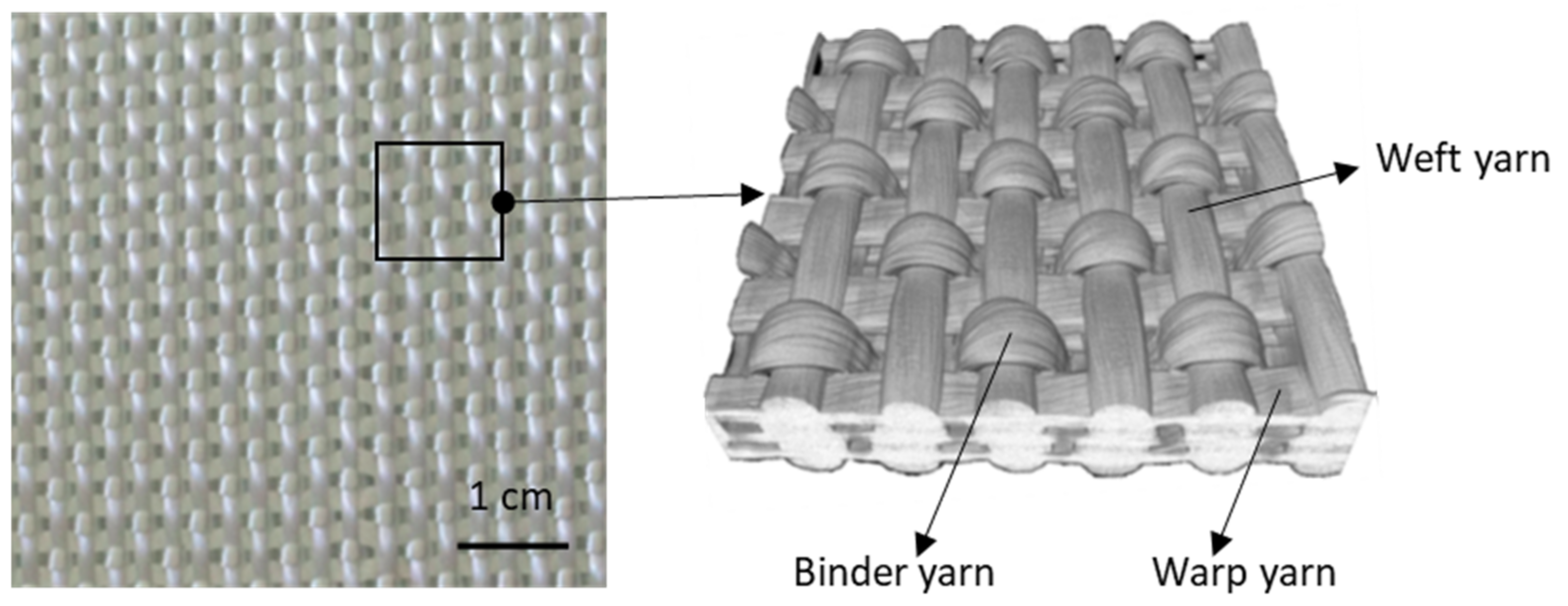
In this context, the objective of this paper is to develop an efficient multi-scale method that allows one to obtain the deformations and orientations of yarns for a whole composite structure during the shaping process of woven reinforcements, with a reasonable computation time. The multi-scale methods that have been developed in the literature consist of creating a passage of information between the macro and meso scales [15,16,17,18,19,20]. This passage makes it possible to transform the deformed information between the macroscopic and mesoscopic scales. In other words, the deformations and the orientations of yarns, as well as the variations of the transverse sections of yarns for the entire composite part, can be calculated from macroscopic forming simulations of woven reinforcements. This proposed method is divided into three main parts: (1) the macroscopic simulation of the woven reinforcements, (2) macro-meso embedded analysis, and (3) the mesoscopic results enriched by a local mesoscopic simulation of RVE. The objective is to present the method in a simple way, postponing the presentation of the laws of macroscopic and mesoscopic behavior to the appendix. The analysis of the number of RVEs in the mesoscopic analysis is presented as well as a comparison of the method with the experiment. The material studied here is an orthogonal 3D glass woven reinforcement (see Figure 1) [21].
2. Macroscopic Analysis of Woven Reinforcements
This part consisted of implementing the numerical simulations of the woven reinforcements at the macroscopic scale using the PlasFib software [22], which calculation codes based on the finite element method (FEM), developed by the LaMCoS laboratory. This finite element code uses a temporal scheme in an explicit dynamic. In macroscopic approaches, woven reinforcements are considered as a continuous medium with a continuous constitutive law. In order to describe the mechanical characteristics of thick textile reinforcements during draping, a 3D hyperelastic constitutive law is applied in the macroscopic simulations [23,24,25]. In this hyperelastic constitutive law, six independent deformation modes of the reinforcement are considered: elongation in the warp and weft direction, transverse compaction, in-plane shear, and transverse shear in the warp and weft direction. The stress–strain relationship is determined through the derivative of the strain energy density , which is the sum of the strain energy of every deformation mode (Equation (1)). Then, the second Piola–Kirchhoff stress tensor can be calculated by the differentiation and the right Cauchy–Green tensor (Equation (2)). , namely , , , , , and , is the physical invariant associated with each deformation mode. In addition, the contribution of curvature in the hexahedral finite elements is taken into account by adding a local flexural stiffness [25].
The characterization of the material parameters was carried out by different classical tests: tensile test, transverse compaction, in-plane shear, transverse shear, and bending test, by means of the inverse method with the Levenberg–Marquardt algorithm. The details of these tests have been described in [17], and the identified material parameters are given in Appendix A.
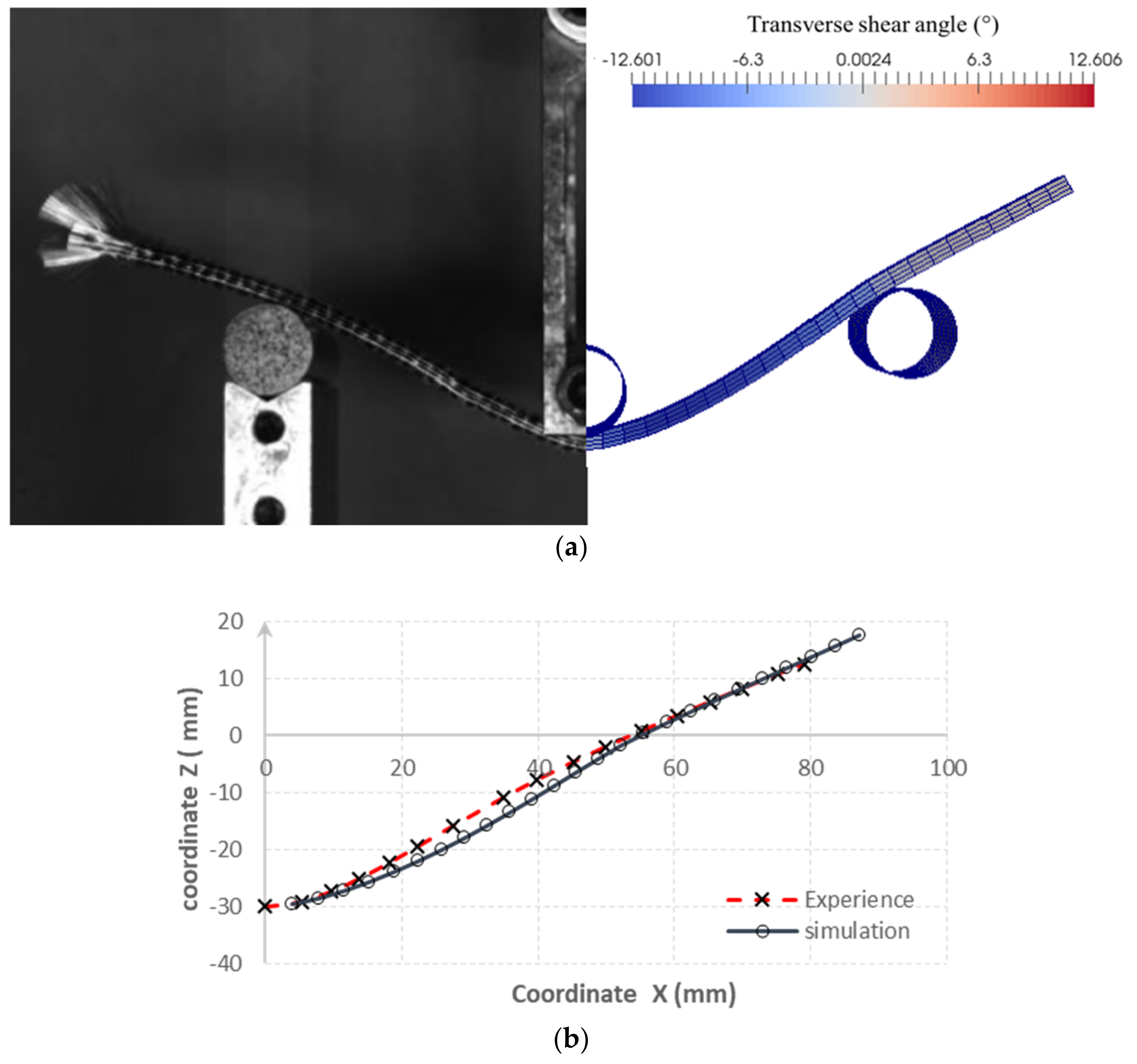
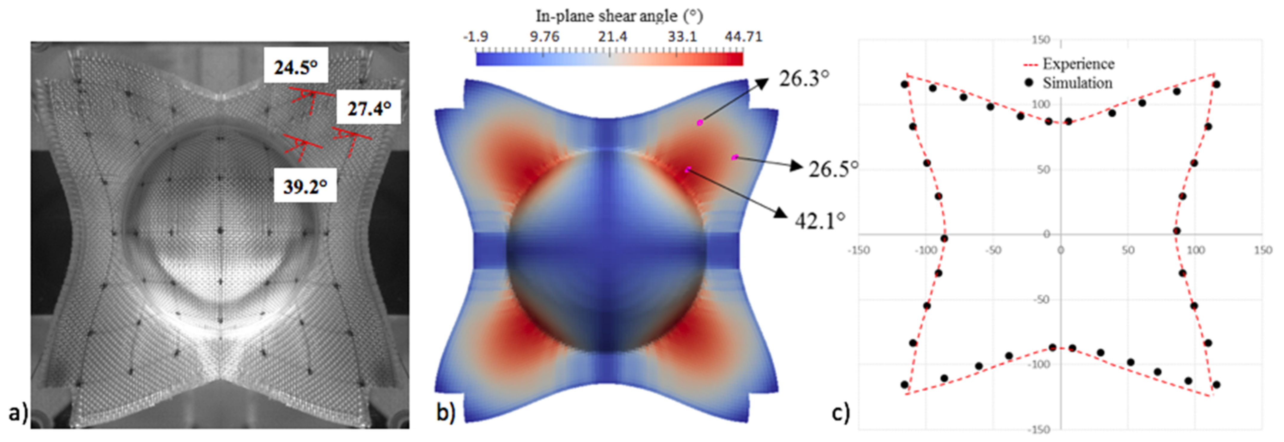
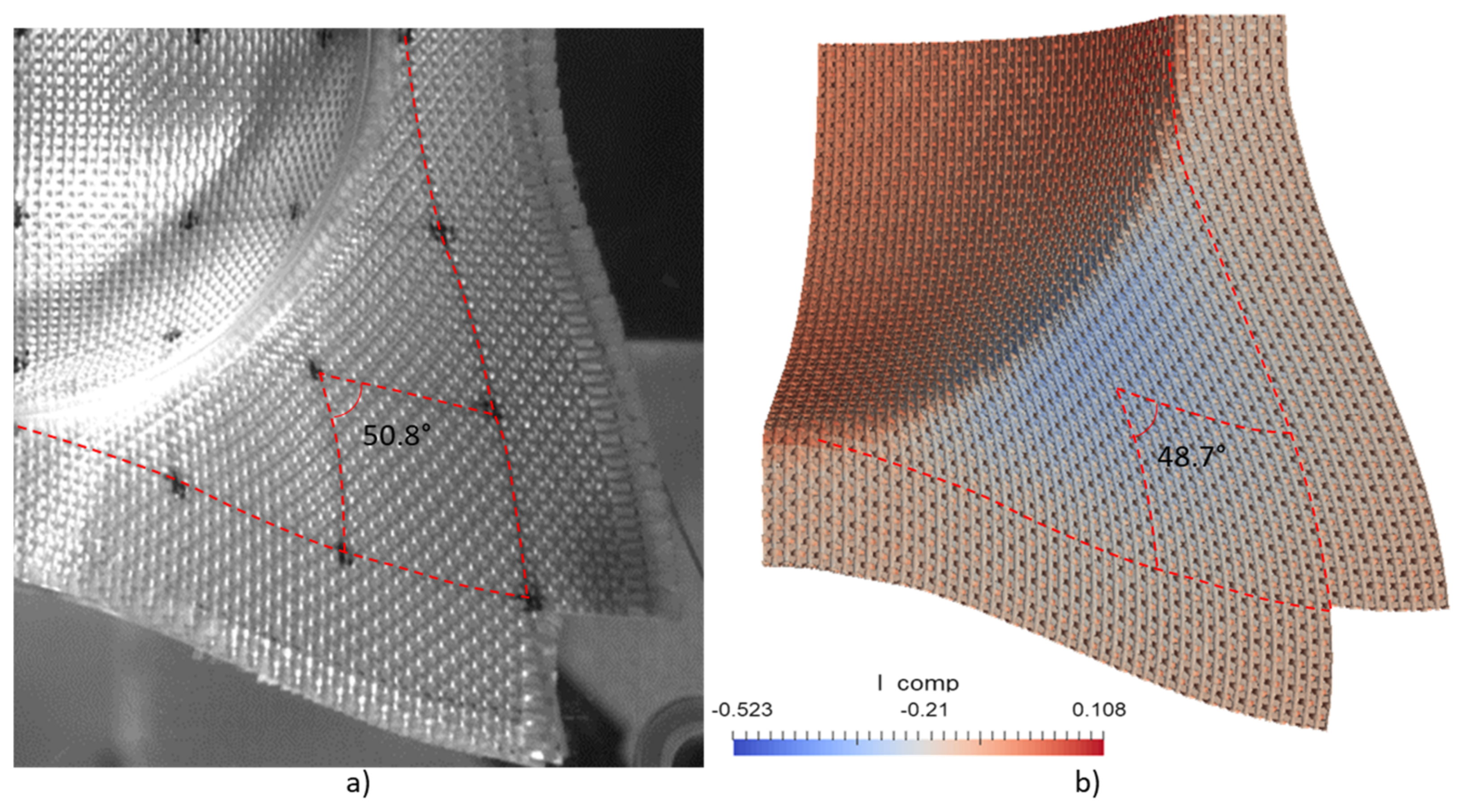
Once all the material parameters in the hyperelastic constitutive law were identified, the forming simulation of reinforcements was carried out in the PlasFib software. Macroscopic simulations were realized in two cases: three-point bending and hemispherical forming (Figure 2 and Figure 3). Finally, in comparison with the corresponding experiments, the results obtained by the simulation were in good agreement. This was the case for the deformed mid-surface of the bending specimen in Figure 2b and for the shear angles after forming the hemisphere in Figure 3.
3. Mesoscopic Analysis by Macro-Meso Embedded Approach
Some mesoscopic models of the entire reinforcement have been used in different studies [8,16,26] to obtain the mesoscopic deformed information of woven composites; however, the size of the numerical model is large and the computational time is long. Therefore, the objective of the developed macro-meso embedded approach is to estimate the deformation of yarns for the entire reinforcement during the forming process with a reasonable computational time.
In this macro-meso embedded approach, the numerical results obtained by the macroscopic simulations of reinforcement are the basis. If the macroscopic results are relevant, they should be able to provide some basic and useful information at the mesoscopic scale. In short, the embedded mesoscopic geometry is determined from the result of the macroscopic simulation.
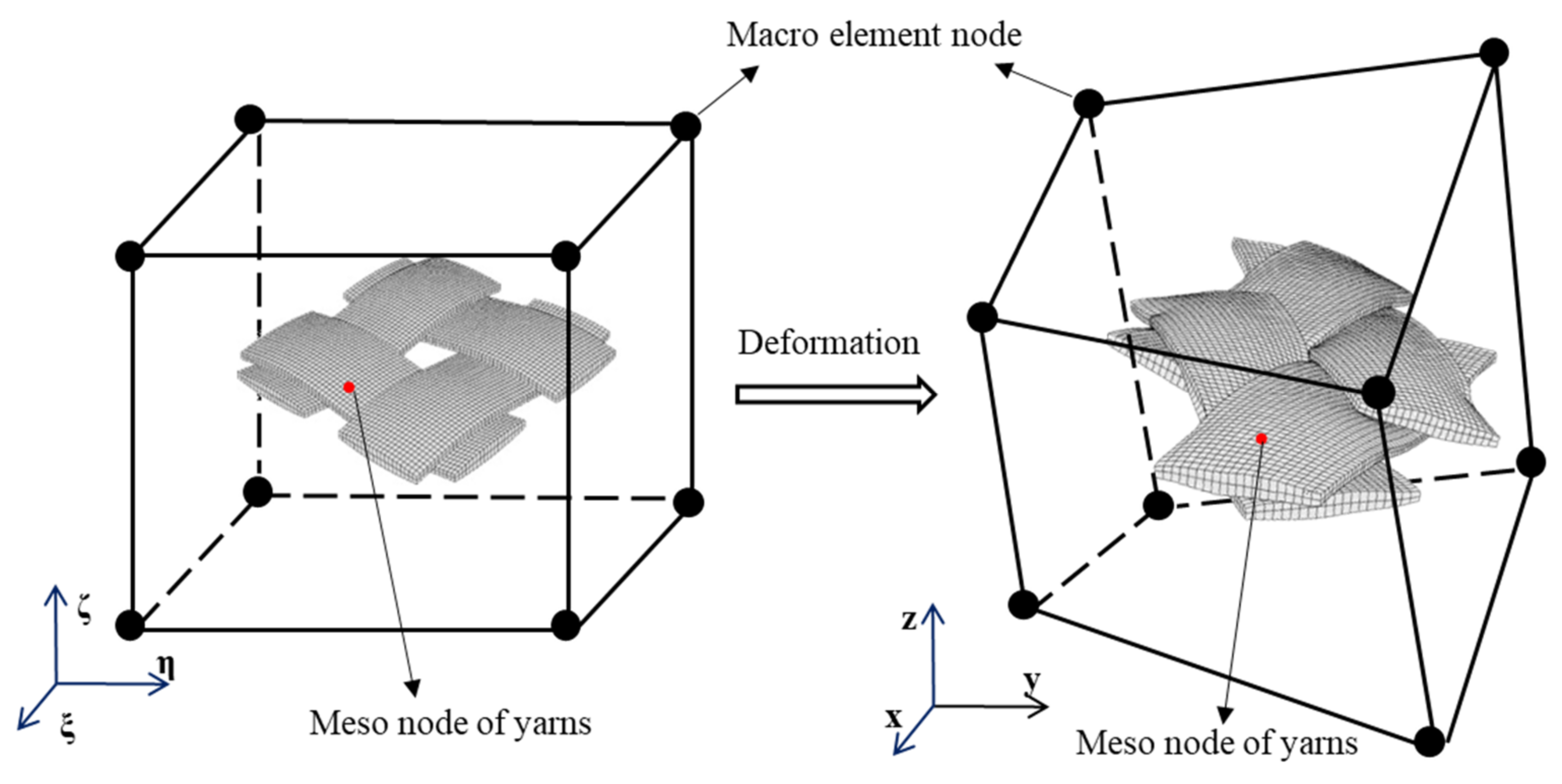
The macro-meso embedded approach allows one to link macroscopic simulations of thick reinforcements and mesoscopic modeling of RVEs (representative volume elements). For periodic textile reinforcements, the geometrical modeling of the RVE is first reconstructed according to X-ray tomography images based on the real geometry of the reinforcement [27]. The modeling of the entire reinforcement at the mesoscopic scale can then be generated in the initial configuration by the repetitions and translations of the RVE. Then, each mesoscopic node of the yarns in the woven reinforcement can be located or integrated into a macroscopic element (Figure 4). During deformation, the integrated mesoscopic element deforms together with the macroscopic element where this mesoscopic element is located, and its mesoscopic nodes have constant natural coordinates in the reference and real macroscopic element.
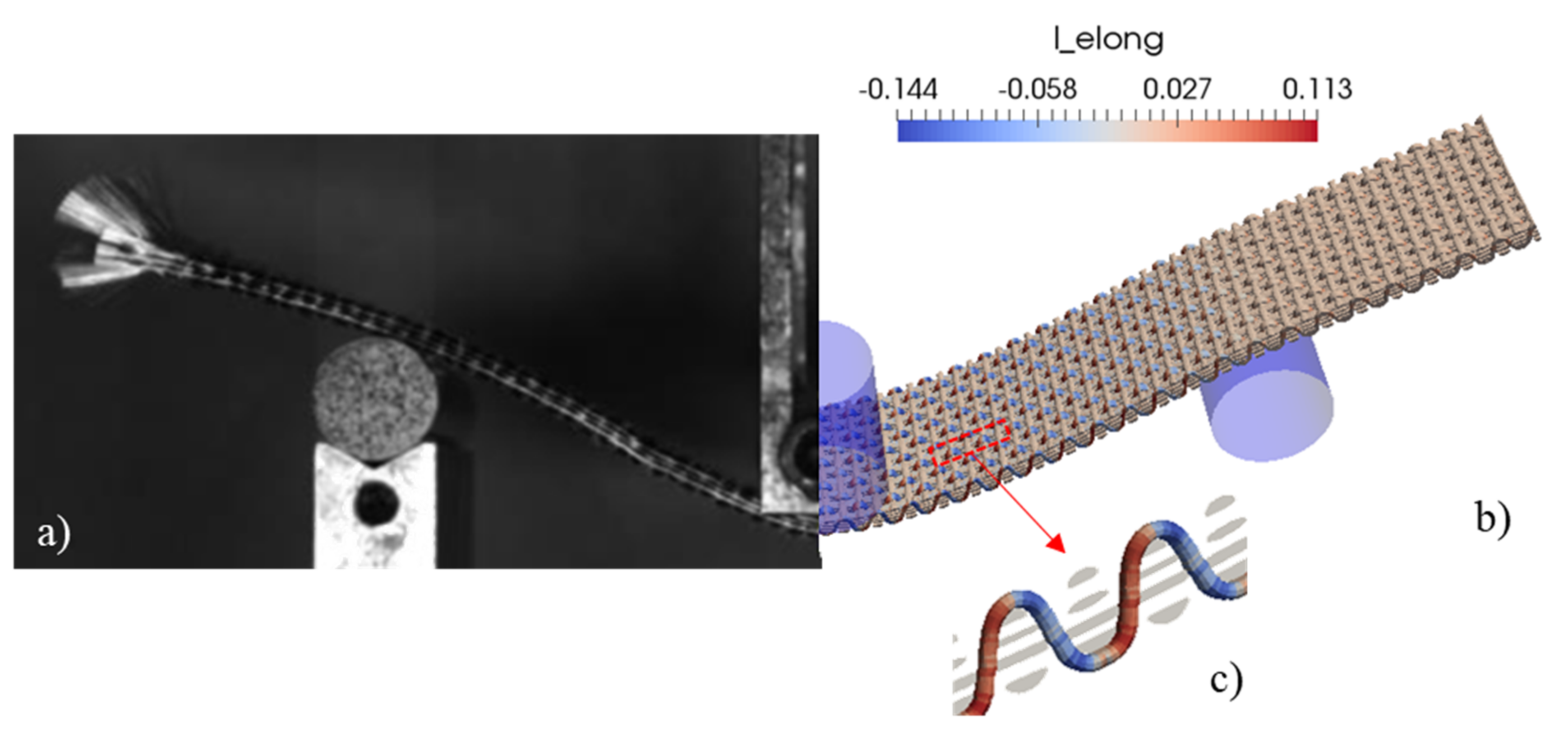
During deformation, the natural coordinates of a mesoscopic node in the corresponding macroscopic element remain identical. In other words, the material position of an embedded mesoscopic node remains constant in the macroscopic element. Therefore, the deformation obtained by the macroscopic simulations can provide a first geometry of reinforcements at the mesoscopic scale in the deformed configuration. As shown in Figure 5 and Figure 6, the mesoscopic deformed geometries of the reinforcement can be obtained by the macro-meso embedded approach.
The mesoscopic results based on macroscopic simulations allow for the determination of the deformations and the deformed orientations of the yarns, and the voids in the elementary cell. The calculation time is very fast, from a few minutes to one hour depending on the reinforcement size.
4. Mesoscopic Analysis Enriched by Local Mesoscopic Simulation
4.1. Local Mesoscopic Simulation
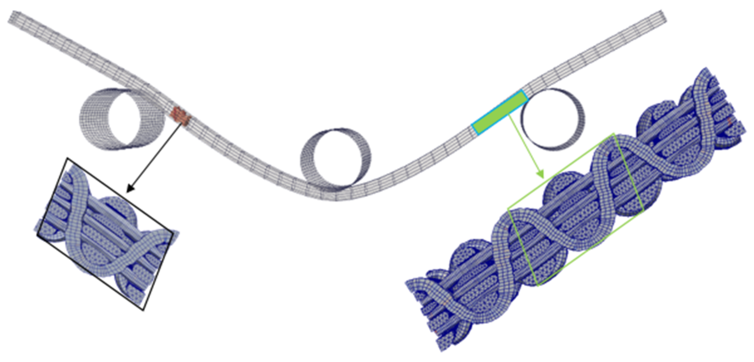
As shown in Section 3, the mesoscopic analyses of the woven reinforcement obtained by the macro-meso embedded approach are efficient in providing a mesoscopic scale solution during shaping. However, this approach is based on the assumptions of continuous medium and the finite element method. The mesoscopic deformed configuration is directly obtained from the macroscopic analysis, without solving a mechanical problem. From the point of view of the constitutive law, the local equilibrium of the stresses is not attained, for example in the red zones in Figure 5. That is to say, local slippages between the yarns is not been taken into account, which can, in some cases, lead to an excessive elongation of yarns. For example, as shown in Figure 5, the local elongation in the yarns obtained by the macro-meso embedded approach can reach 11%, which is much higher than the reality. In order to overcome this difficulty, a local mesoscopic simulation based on macroscopic simulations and macro-meso embedded mesoscopic analysis is proposed.
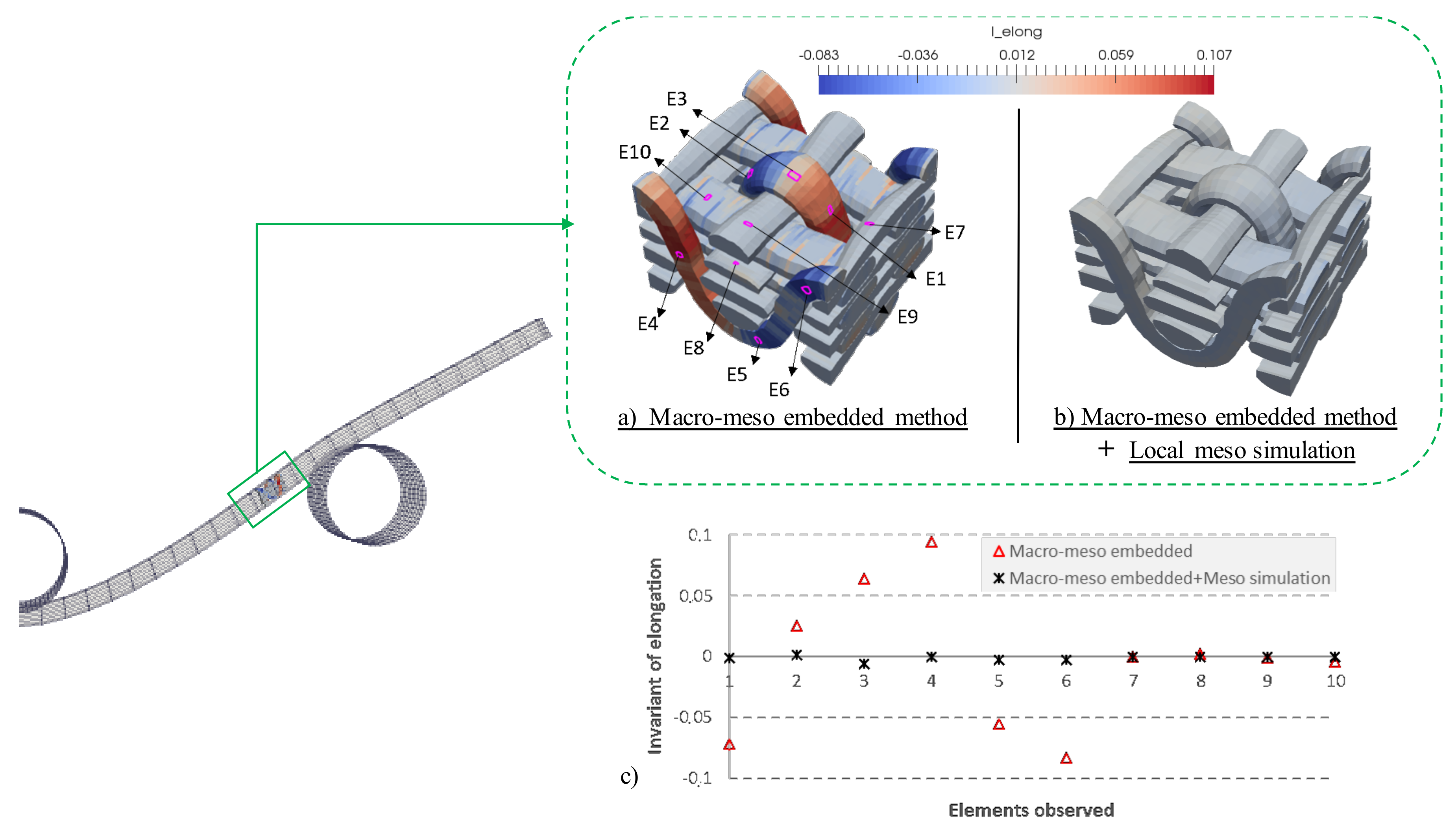
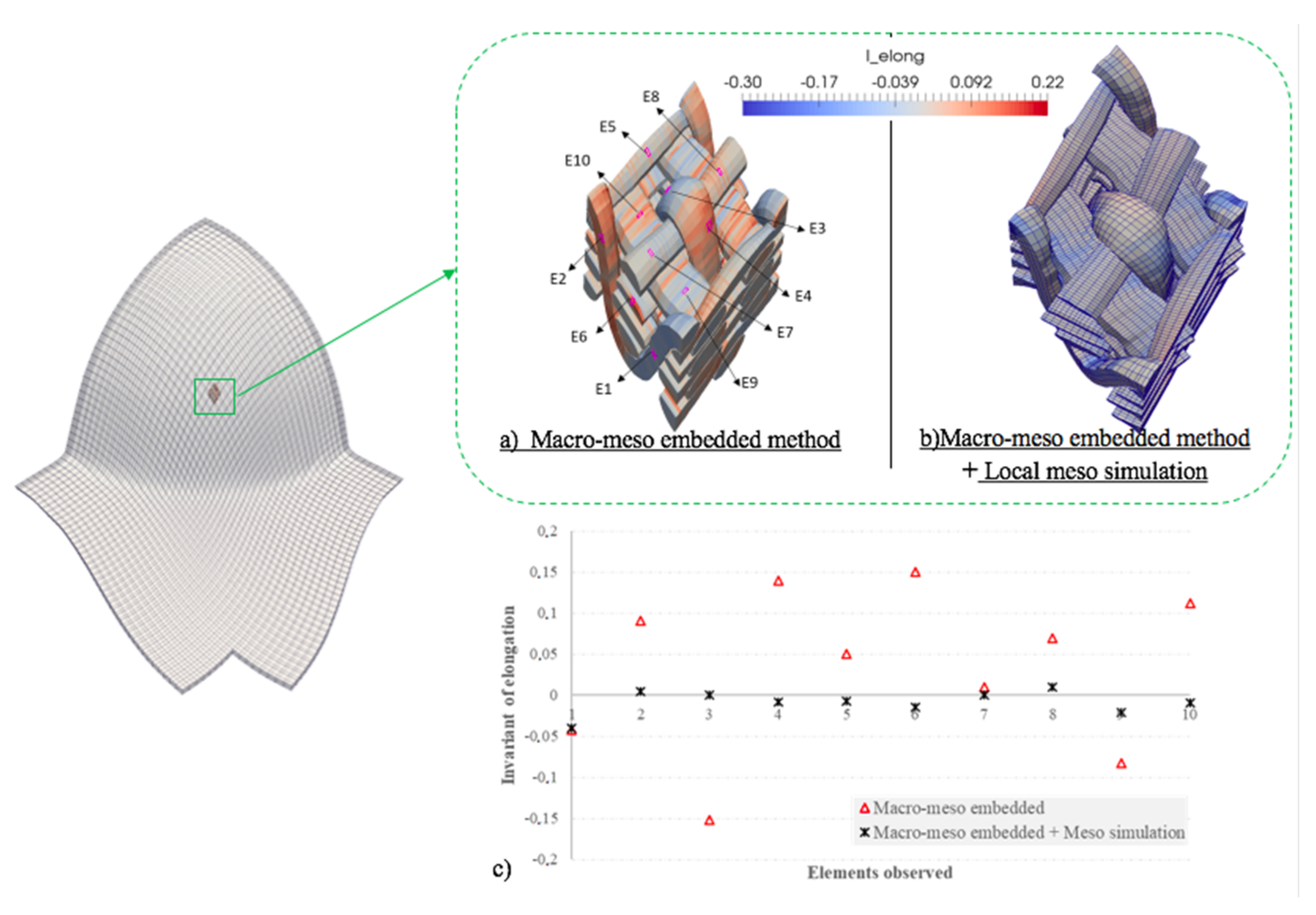
The local mesoscopic simulation is performed locally, usually on one or more representative volume elements (RVEs) based on the results of the macro-meso embedded approach. The deformed configuration obtained by the embedded mesoscopic simulation constitutes the initial state of the local mesoscopic simulation. A relatively simple transverse isotropic hyperelastic behavior law (neo-Hookean) was used to describe the mechanical behavior of the yarns [28,29]. The material parameters used are given in Appendix B. Consequently, stress equilibrium was achieved within the yarns and the local mesoscopic simulation eliminated the phenomena of the excessive elongation of yarns. The results obtained by the local mesoscopic simulation are compared with the results obtained by the macro-meso embedded approach in Figure 7 and Figure 8. In both cases, the spurious elongations obtained in the yarns by the embedded calculation were reduced to small values after the mesoscopic calculation on a RVE both in the bending case (Figure 7) and in the hemispherical forming case (Figure 8). In addition, the calculation time of each step in this multi-scale method is shown in Table 1.
4.2. Comparison with Experimental Results
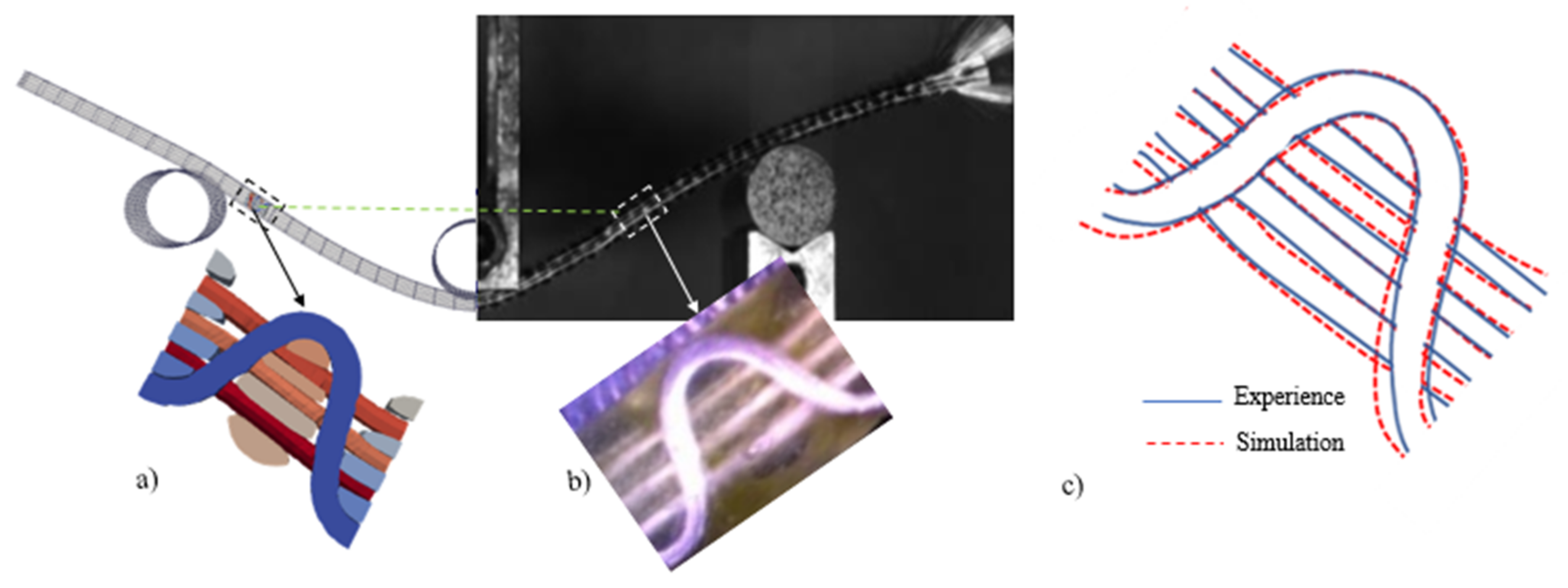
Finally, the mesoscopic numerical results are compared with the experimental results and the numerical results with three RVEs for three-point bending. The deformations of the longitudinal and transverse sections of the yarns were observed and analyzed by a microscope.
4.3. Influence of the Number of RVEs
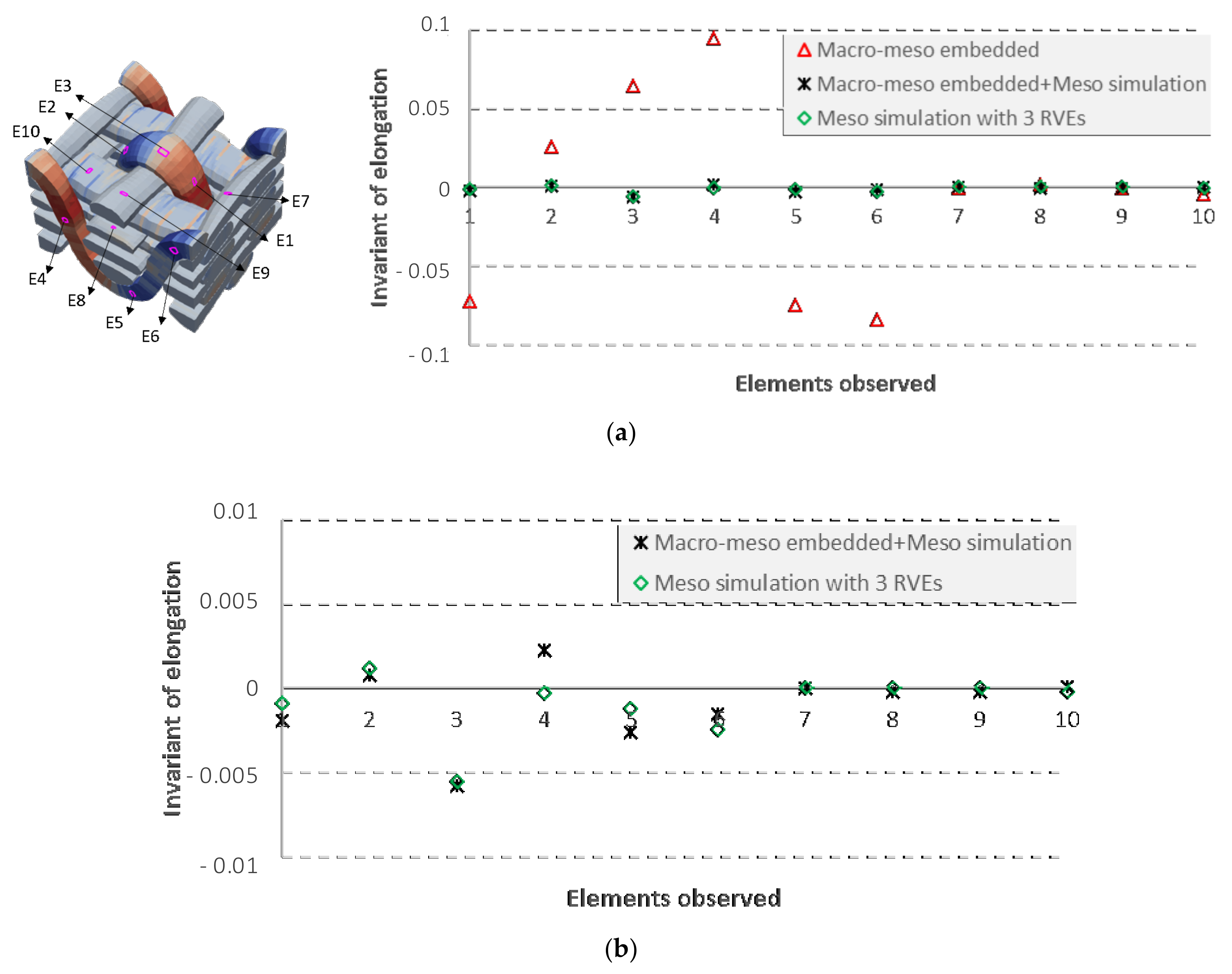
The local mesoscopic simulation was performed on a single RVE, and the boundary conditions from the macro-meso embedded approach were applied on the RVE edges. The influence of the number of RVEs was not taken into account. Therefore, to analyze the edge effects on the mesoscopic results, another simulation was carried out on three successive RVEs for three-point bending, in which the middle RVE had the same location as the single RVE. The results shown in in Figure 10 and Figure 11 indicate that the number of RVEs had only a very weak influence on the mesoscopic results.
5. Conclusions
The deformation information of woven reinforcements on the mesoscopic scale is essential to evaluate the mechanical properties of the final composite part, as well as to simulate resin flow during the next injection step. In this paper, the developed macro-meso embedded approach allows one to obtain the deformed configuration at the mesoscopic scale of woven reinforcements during the forming process. However, it has drawbacks, especially the excessive elongation of the yarns. To overcome this problem, a local mesoscopic simulation that takes into account the local slippage of yarns can be carried out by defining specific boundary conditions. This step requires a reasonable computational cost. The results of one RVE were satisfactory in comparison with the experimental results and the numerical results with three RVEs. Furthermore, the comparison with the full meso simulation at a large scale was interesting. Another perspective to validate the quality of the multi-scale approach consists in using the Hill–Mandell macro-homogeneity condition to ensure that the same amount of energy is dissipated in the RVE and the corresponding part of material in the macro-model.
Author Contributions
J.W.: investigation, methodology, software, validation, visualization, and writing—original draft. P.W.: investigation. N.H.: software and supervision. P.B.: conceptualization, methodology, supervision. All authors have read and agreed to the published version of the manuscript.
Funding
This research received no external funding.
Institutional Review Board Statement
Not applicable.
Informed Consent Statement
Not applicable.
Data Availability Statement
Not applicable.
Conflicts of Interest
The authors declare no conflict of interest.
Appendix A
The 3D hyperelastic anisotropic constitutive law is applied in the macroscopic simulations. The second Piola–Kirchhoff stress tensor can be calculated by the differentiation and the right Cauchy–Green tensor (see Equation (2) in Section 2). For each deformation mode, the physical invariant Ik described in Section 2 is defined by the classical invariants (Equation (A1)), and the strain energy density wk can be expressed in polynomial form (Equation (A2)). In order to take into consideration the curvature of the fibers, an independent bending stiffness of fibers χ is added to calculate the bending moment Mbend by Equation A3. The material parameters ki, D0, and D1 are characterized by the corresponding mechanical tests (Table A1).

Table A1.
Material parameters identified in the macroscopic simulations (ki in MPa; D0 in Nmm; D1 in Nmm2).
Table A1.
Material parameters identified in the macroscopic simulations (ki in MPa; D0 in Nmm; D1 in Nmm2).
| welong1/2 | k1 | k2 | k3 | k4 | k5 | k6 |
| 8.692 | 4816 | −1.002 × 10⁶ | 8.275 × 10⁷ | −2.419 × 10⁹ | 2.442 × 10¹⁰ | |
| k7 | k8 | k9 | k10 | k11 | k12 | |
| 8.692 | −505.6 | 1.073 × 10⁵ | −2.687 × 10⁶ | 0 | 0 | |
| wcomp | k1/k7 | k2/k8 | k3/k9 | k4/k10 | k5/k11 | k6/k12 |
| 9.69 × 10⁻² | 0.7009 | 6.426 × 10⁻² | −1.339 | 0.8777 | 2.855 × 10⁻² | |
| wsh | k1/k7 | k2/k8 | k3/k9 | k4/k10 | k5/k11 | k6/k12 |
| 0.3441 | −2.019 | 7.416 | −14.01 | 14.01 | −5.444 | |
| wshT1 | k1/k7 | k2/k8 | k3/k9 | k4/k10 | k5/k11 | k6/k12 |
| 3.721 × 10⁻² | 3.844 × 10⁻² | −0.521 | 1.877 | −2.78 | 1.572 | |
| wshT2 | k1/k7 | k2/k8 | k3/k9 | k4/k10 | k5/k11 | k6/k12 |
| 347.3 | −5.674 × 10⁻² | −1.46 × 10⁻² | 0.5835 | −1.201 | 0.8084 | |
| D0 (warp) | D1 (warp) | D0 (weft) | D1 (weft) | |||
| 3.6 | 117.9 | 3.748 | 123.6 |
Appendix B
In the hyperelastic transverse isotropic (Neo-Hookean) constitutive law, the potential is considered to consist of two potentials [28]: the isotropic potential wiso, concerning the longitudinal behavior of a yarn, and the potential wtrans, concerning the mechanical behavior in the transverse plane of a yarn (Equation (A4)).
For simplification, the parameters λ, μ, α, β and γ are defined by four material parameters in Equation (A5): transverse modulus of elasticity E, longitudinal modulus of elasticity EA, Poisson’s ratio ν, and longitudinal shear modulus GA, respectively. The material parameters used in the mesoscopic simulation are given in Table A2 (details in [29]).
Table A2.
Material parameters identified in the mesoscopic simulations (in MPa).
| E | EA_Elongation | EA_Compression | GA | |
|---|---|---|---|---|
| 3200 | 45,516 | 100 | 0 | 1600 |
References
- Ten Thije, R.H.W.; Akkerman, R.; Huétink, J. Large deformation simulation of anisotropic material using an updated Lagrangian finite element method. Comput. Methods Appl. Mech. Eng. 2007, 196, 3141–3150. [Google Scholar] [CrossRef]
- Boisse, P. Finite element analysis of composite forming. In Composites Forming Technologies; Woodhead Publishing: Cambridge, UK, 2007; pp. 46–79. [Google Scholar]
- Gereke, T.; Döbrich, O.; Hübner, M.; Cherif, C. Experimental and computational composite textile reinforcement forming: A review. Compos. A Appl. Sci. Manuf. 2013, 46, 1–10. [Google Scholar] [CrossRef]
- Bussetta, P.; Correia, N. Numerical forming of continuous fibre reinforced composite material: A review. Compos. A Appl. Sci Manuf. 2018, 113, 12–31. [Google Scholar] [CrossRef]
- Boisse, P.; Hamila, N.; Vidal-Sallé, E.; Dumont, F. Simulation of wrinkling during textile composite reinforcement forming. Influence of tensile, in-plane shear and bending stiffnesses. Compos. Sci. Technol. 2011, 71, 683–692. [Google Scholar] [CrossRef] [Green Version]
- Dangora, L.M.; Mitchell, C.J.; Sherwood, J.A. Predictive model for the detection of out- of-plane defects formed during textile-composite manufacture. Compos. A Appl. Sci. Manuf. 2015, 78, 102–112. [Google Scholar] [CrossRef]
- Chen, X.; Zhu, F.; Wells, G. An analytical model for ballistic impact on textile based body armour. Compos. Part B Eng. 2013, 45, 1508–1514. [Google Scholar] [CrossRef]
- Gatouillat, S.; Bareggi, A.; Vidal-Sallé, E.; Boisse, P. Meso modelling for composite preform shaping–simulation of the loss of cohesion of the woven fibre network. Compos. A Appl. Sci. Manuf. 2013, 54, 135–144. [Google Scholar] [CrossRef]
- Allaoui, S.; Hivet, G.; Soulat, D.; Wendling, A.; Ouagne, P.; Chatel, S. Experimental preforming of highly double curved shapes with a case corner using an interlock reinforcement. Int. J. Mater. Form. 2014, 7, 155–165. [Google Scholar] [CrossRef]
- Schirmaier, F.J.; Dörr, D.; Henning, F.; Kärger, L. A macroscopic approach to simulate the forming behaviour of stitched unidirectional non-crimp fabrics (UD-NCF). Compos. A Appl. Sci. Manuf. 2017, 102, 322–335. [Google Scholar] [CrossRef]
- Schirmaier, F.J.; Weidenmann, K.A.; Kärger, L.; Henning, F. Characterisation of the draping behaviour of unidirectional non-crimp fabrics (UD-NCF). Compos. A Appl. Sci. Manuf. 2016, 80, 28–38. [Google Scholar] [CrossRef]
- Bréard, J.; Henzel, Y.; Trochu, F.; Gauvin, R. Analysis of dynamic flows through porous media. Part I: Comparison between saturated and unsaturated flows in fibrous reinforcements. Polym. Compos. 2003, 24, 391–408. [Google Scholar] [CrossRef]
- Loix, F.; Badel, P.; Orgéas, L.; Geindreau, C.; Boisse, P. Woven fabric permeability: From textile deformation to fluid flow mesoscale simulations. Compos. Sci. Technol. 2008, 68, 1624–1630. [Google Scholar] [CrossRef]
- Tran, T.; Comas-Cardona, S.; Abriak, N.E.; Binetruy, C. Unified microporomechanical approach for mechanical behavior and permeability of misaligned unidirectional fiber reinforcement. Compos. Sci. Technol. 2010, 70, 1410–1418. [Google Scholar] [CrossRef] [Green Version]
- Llorca, J.; Gonzalez, C.; Molina-Aldaregui, J.M.; Segurado, J.; Seltzer, R.; Sket, F. Multiscale modelling of composite materials: A road map towards virtual testing. Adv. Mater. 2011, 23, 5130–5147. [Google Scholar] [CrossRef]
- Iwata, A.; Inoue, T.; Naouar, N.; Boisse, P.; Lomov, S.V. Coupled meso-macro simulation of woven fabric local deformation during draping. Compos. A Appl. Sci. Manuf. 2019, 118, 267–280. [Google Scholar] [CrossRef]
- Wang, J.; Wang, P.; Hamila, N.; Boisse, P. Mesoscopic analyses of the draping of 3D woven composite reinforcements based on macroscopic simulations. Compos. Struct. 2020, 250, 112602. [Google Scholar] [CrossRef]
- Whitcomb, J.; Srirengan, K.; Chapman, C. Evaluation of homogenization for global/local stress analysis of textile composites. Compos. Struct. 1995, 31, 137–149. [Google Scholar] [CrossRef]
- Carvelli, V.; Poggi, C. A homogenization procedure for the numerical analysis of woven fabric composites. Compos. A Appl. Sci Manuf. 2001, 32, 1425–1432. [Google Scholar] [CrossRef]
- Lomov, S.V.; Ivanov, D.S.; Verpoest, I.; Zako, M.; Kurashiki, T.; Nakai, H.; Hirosawa, S. Meso-FE modelling of textile composites: Road map, data flow and algorithms. Compos. Sci. Technol. 2007, 67, 1870–1891. [Google Scholar] [CrossRef]
- Chen, X. (Ed.) Advances in 3D Textiles; Elsevier: Amsterdam, The Netherlands, 2015. [Google Scholar]
- Software PLASFIB. Inter Deposit Certification; Agence Pour la Protection des Programmes: Paris, France, 2015. [Google Scholar]
- Boisse, P.; Aimène, Y.; Dogui, A.; Dridi, S.; Gatouillat, S.; Hamila, N.; Vidal-Sallé, E. Hypoelastic, hyperelastic, discrete and semi-discrete approaches for textile composite reinforcement forming. Int. J. Mater. Form. 2010, 3, 1229–1240. [Google Scholar] [CrossRef]
- Charmetant, A.; Orliac, J.G.; Vidal-Sallé, E.; Boisse, P. Hyperelastic model for large deformation analyses of 3D interlock composite preforms. Compos. Sci. Technol. 2012, 72, 1352–1360. [Google Scholar] [CrossRef]
- Mathieu, S.; Hamila, N.; Bouillon, F.; Boisse, P. Enhanced modeling of 3D composite preform deformations taking into account local fiber bending stiffness. Compos. Sci. Technol. 2015, 117, 322–333. [Google Scholar] [CrossRef]
- Creech, G.; Pickett, A.K. Meso-modelling of non-crimp fabric composites for coupled drape and failure analysis. J. Mater. Sci. 2006, 41, 6725–6736. [Google Scholar] [CrossRef]
- Naouar, N.; Vidal-Salle, E.; Schneider, J.; Maire, E.; Boisse, P. 3D composite reinforcement meso FE analyses based on X-ray computed tomography. Compos. Struct. 2015, 132, 1094–1104. [Google Scholar] [CrossRef]
- Bonet, J.; Burton, A.J. A simple orthotropic, transversely isotropic hyperelastic constitutive equation for large strain computations. Comput. Methods Appl. Mech. Eng. 1998, 162, 151–164. [Google Scholar] [CrossRef]
- Florimond, C. Contribution à la Modélisation Mécanique du Comportement de Mèches de Renforts Tissés à L’Aide d’un Schéma Éléments Finis Implicite. Ph.D. Thesis, INSA Lyon, Lyon, France, 2015. [Google Scholar]
Figure 1.
Structure of the 3D non-crimp orthogonal woven fabric by X-ray tomography and its mesh.

Figure 2.
Comparisons between the numerical and experimental results for three-point bending (a) deformed geometry and (b) the deformation of the middle line of the reinforcement.
Figure 2.
Comparisons between the numerical and experimental results for three-point bending (a) deformed geometry and (b) the deformation of the middle line of the reinforcement.

Figure 3.
Comparisons between the experimental and numerical results for hemispherical forming. (a,b) In-plane shear angle in the same position. (c) Deformed geometry.
Figure 3.
Comparisons between the experimental and numerical results for hemispherical forming. (a,b) In-plane shear angle in the same position. (c) Deformed geometry.

Figure 4.
Meso node of yarns embedded in a macro element. Reference and real frames.

Figure 5.
Three-point bending. (a) Deformed geometry in experimental result. (b) Elongation of yarns in mesoscopic analysis. (c) Elongation of an extracted yarn.
Figure 5.
Three-point bending. (a) Deformed geometry in experimental result. (b) Elongation of yarns in mesoscopic analysis. (c) Elongation of an extracted yarn.

Figure 6.
Hemispherical stamping. (a) Deformed geometry in experimental result. (b) Compaction of yarns in mesoscopic analysis.
Figure 6.
Hemispherical stamping. (a) Deformed geometry in experimental result. (b) Compaction of yarns in mesoscopic analysis.

Figure 7.
Influence of the enriched local mesoscopic simulation on the elongation of yarns in three-point bending. (a) Macro-meso embedded analysis. (b) Macro-meso embedded method with local mesoscopic simulation analysis. (c) Change in elongation for the same elements.
Figure 7.
Influence of the enriched local mesoscopic simulation on the elongation of yarns in three-point bending. (a) Macro-meso embedded analysis. (b) Macro-meso embedded method with local mesoscopic simulation analysis. (c) Change in elongation for the same elements.

Figure 8.
Influence of the enriched local mesoscopic simulation on the elongation of yarns in hemispherical forming. (a) Macro-meso embedded analysis. (b) Macro-meso embedded method with local mesoscopic simulation analysis. (c) Change in elongation for the same elements.
Figure 8.
Influence of the enriched local mesoscopic simulation on the elongation of yarns in hemispherical forming. (a) Macro-meso embedded analysis. (b) Macro-meso embedded method with local mesoscopic simulation analysis. (c) Change in elongation for the same elements.

Figure 9.
Deformed geometry of RVE in the same position obtained by: (a) simulation, (b) experiment, and (c) comparison of the outlines of binder yarns and warp yarns.
Figure 9.
Deformed geometry of RVE in the same position obtained by: (a) simulation, (b) experiment, and (c) comparison of the outlines of binder yarns and warp yarns.

Figure 10.
Influence of the number of RVEs on the meso results.

Figure 11.
Comparisons of yarn elongation for ten elements in the same positions between the
meso results of one RVE and threes RVEs: (a) with the result of Macro-Meso embedded approach,
(b) without the result of Macro-Meso embedded approach.
Figure 11.
Comparisons of yarn elongation for ten elements in the same positions between the
meso results of one RVE and threes RVEs: (a) with the result of Macro-Meso embedded approach,
(b) without the result of Macro-Meso embedded approach.

Table 1.
Calculation time of three-point bending and hemispherical forming.
| Size of Model RVE: 4.78 × 4.64 × 3.25 mm3 | Number of Elements (RVE: 39,888 Elements) | Calculation Time | |||
|---|---|---|---|---|---|
| Macro Simulation | Macro-Meso Embedded Analysis | Meso Local Simulation | |||
| Three-point bending | 41 RVEs | 1.6 millions | 6 h | 15 min | 30 min |
| Hemispherical forming | 625 RVEs | 25 millions | 1 day | 1 h | 2 h |
Publisher’s Note: MDPI stays neutral with regard to jurisdictional claims in published maps and institutional affiliations. |
© 2022 by the authors. Licensee MDPI, Basel, Switzerland. This article is an open access article distributed under the terms and conditions of the Creative Commons Attribution (CC BY) license (https://creativecommons.org/licenses/by/4.0/).
Share and Cite
MDPI and ACS Style
Wang, J.; Wang, P.; Hamila, N.; Boisse, P. Meso-Macro Simulations of the Forming of 3D Non-Crimp Woven Fabrics. Textiles 2022, 2, 112-123. https://0-doi-org.brum.beds.ac.uk/10.3390/textiles2010006
AMA Style
Wang J, Wang P, Hamila N, Boisse P. Meso-Macro Simulations of the Forming of 3D Non-Crimp Woven Fabrics. Textiles. 2022; 2(1):112-123. https://0-doi-org.brum.beds.ac.uk/10.3390/textiles2010006
Chicago/Turabian StyleWang, Jie, Peng Wang, Nahiene Hamila, and Philippe Boisse. 2022. "Meso-Macro Simulations of the Forming of 3D Non-Crimp Woven Fabrics" Textiles 2, no. 1: 112-123. https://0-doi-org.brum.beds.ac.uk/10.3390/textiles2010006