
Corium Experimental Thermodynamics: A Review and Some Perspectives

Institut de Radioprotection et Sûreté Nucléaire (IRSN), F-13115 St Paul Lez Durance, France
Thermo 2021, 1(2), 179-204; https://0-doi-org.brum.beds.ac.uk/10.3390/thermo1020013
Submission received: 22 June 2021
/
Revised: 22 July 2021
/
Accepted: 2 August 2021
/
Published: 11 August 2021
(This article belongs to the Special Issue Thermodynamics and Nuclear Materials)
Abstract
:More than 30 years ago a specialist meeting was held at Joint Research Center Ispra (Italy) from 15 to 17 January 1990 to review the current understanding of chemistry during severe accidents in light water reactors (LWR). Let us consider that, at the end of the 1980s, thermodynamics introduced in the severe accident codes was really poor. Only some equilibrium constants for a few simple reactions between stoichiometric compounds were used as well as some simple correlations giving estimates of solidus and liquidus temperatures. In the same time, the CALPHAD method was developed and was full of promise to approximate the thermodynamic properties of a complex thermochemical system by the way of a critical assessment of experimental data, a definition of a simple physical model and an optimisation procedure to define the values of the model parameters. It was evident that a nuclear thermodynamic database had to be developed with that new technique to obtain quite rapidly prominent progress in the knowledge of thermochemistry in the severe accident research area. Discussions focused on the important chemical phenomena that could occur across the wide range of conditions of a damaged nuclear plant. The most pressing need for improved chemical models is identified with condensed phase mixtures to model the corium progression. This paper reviews more than 30 years of experimental data production in the field of corium thermodynamics. This work has been conducted through multiple international programs (EURATOM, ISTC, OECD) as well as through more specific studies conducted at the national scale. This research has been capitalised in specific databases such as NUCLEA and TAF-ID, databases developed at IRSN and at CEA, respectively, and are now used in degradation models of the severe accident simulation codes. This research is presented in this paper. In the conclusion, we outline the research perspectives that need to be considered in order to address today’s and tomorrow’s issues.
1. Introduction
In order to understand and model all the physical phenomena that can occur during a severe accident, a good knowledge of the materials properties is essential. During such an accident, temperatures of more than 2750 °C can be reached. In these extreme conditions the various materials of the different core components (absorber rod, cladding, fuel, etc.) melt and interact to form complex mixtures (commonly called corium).
Corium is generally characterised by the presence of a large number of chemical elements and may present a multiphase aspect (e.g., a mixture of a liquid phase and solid phases, a mixture of two immiscible liquid phases, etc.). Therefore, the assessment of the properties must not only cover the materials constituting the individual core components but also the mixtures resulting from the interaction of these materials with each other over a temperature range theoretically from the nominal operating temperature of the reactor to temperatures up to fuel melting (2850 °C for UO2). It is easy to understand the difficulty of the task both experimentally and in terms of modelling.
For more than 30 years, numerous programmes have made it possible to make progress in this undertaking. In the framework of the European Commission EURATOM Framework Programmes (FPs) [1,2,3,4,5,6,7], the International Science and Technology Centre (ISTC) Programmes [8,9], the SARNET Networks of Excellence [10,11] and the Organisation for Economic Cooperation and Development (OECD) Programmes [12,13], severe accident experts have been interested in the production and the assessment of thermodynamic data for a number of compounds of reactor materials and fission products and complex phases mixing a large number of chemical elements. Using the CALPHAD method, thermodynamic databases for collecting all this knowledge in a consistent way have been developed [14,15,16]. Thanks to previously mentioned international programmes, in particular to the European Commission EURATOM Programmes, the European tool NUCLEA [14], has been developed for in- and ex-vessel corium applications, and intensively and continuously validated at IRSN [10,11], until now, with the technical support of the SIMAP Laboratory (Grenoble, France) and the contributions from EDF and CEA. Such a database is much more than a compilation of thermodynamic data from various sources. Its constitution needs considerable analysis for self-consistency, to ensure that all the available experimental information is satisfactorily reproduced. It is used today in the interpretation of experiments simulating specific sequences of the accident as well as in the severe accident modelling (e.g., ASTEC code).
During a severe accident sequence in light water reactors (LWRs), implying partial or complete core melting, thermodynamic models are required to predict the behaviour of the melts formed from the degradation of the core materials. Data such as the composition of the phases present in the corium and their properties (solidus and liquidus temperatures, heat capacities, enthalpies, etc.) are key parameters for modelling, among other things, of the corium flow properties and then for modelling of the progression of the accident. Of particular importance is the determination of “critical” (in terms of importance for the accident progression) temperatures, above which significant amounts of liquid phase form as a result of chemical interactions between some core components or by reaching a melting point of one material.
According to the general understanding of the phenomena occurring during a severe accident [17,18] and on the basis of the experimental results and thermodynamic considerations, it is possible to roughly distinguish, in a typical accident sequence, four different temperature regimes in which liquid phases of different nature may be formed in the reactor, leading to substantial material relocations and different degrees of core damage, from limited degradations in the core to formation of a large molten pool in the bottom of the reactor vessel and possible ex-vessel progression involving relocation of molten core debris into the reactor cavity (Figure 1):
- The first regime is characterised by the melting of the absorber rods and the eutectic reaction between some metallic components in the core. The upper temperature of this regime approximately corresponds to the melting point of stainless steel (around 1450 °C) while the lower temperature around 800 °C is linked to the liquefaction of the Ag-Cd-In absorber alloy.
- In the so-called intermediate regime, which extends to 2300 °C, the fuel liquefaction due to its interaction with molten Zircaloy takes place and constitutes the main degradation process occurring in the core. Formation of local pools may form in the core.
- At temperature above 2300 °C (some papers mentioned temperatures slightly below 2300 °C [19,20]), a (partial) relocation of the fuel rod materials occurs resulting in the formation of a more or less large molten pool. This is the third regime. It is usually characterised by an evolution of the corium composition from the metal-oxide region of the U-O-Zr-stainless steel system towards the fully oxide one, depending on available water and the oxidation process.
- The vessel rupture and the ex-vessel progression of a severe accident in a PWR involve the relocation of molten core debris into the reactor cavity. The molten materials are able to interact with the concrete of the basemat resulting in ablation and release of species by vaporisation. The composition of the melt changes progressively as the basemat decomposition products are incorporated into the melt during the molten core–concrete interaction.
In this paper, we propose to review the experimental results obtained for these different regimes in the field of corium thermodynamics by trying to relate the data obtained with the issues of the severe accident progression. The paper is divided in four parts, reflecting the temperature scale previously described.
2. Low Temperature Regime (below 1450 °C)
In light water reactors (LWR), boron carbide (B4C) and silver-indium-cadmium (SIC) alloy are the most widely used neutron absorber materials in absorber rods and blades. In a severe accident situation, the decay heat in the core is no longer dissipated sufficiently to avoid the increase of temperatures in the core. These absorber rods are, then, the first components of the core to degrade in such uncontrolled situation.
For the SIC alloy, this temperature increase causes the absorber alloy (usual composition is 80 wt.% Ag, 15 wt.% In, 5 wt.% Cd, solid solution so-called SIC) to “melt” at a temperature of 800 ± 10 °C [21]. It should be noted that this is the material with the lowest melting point in the reactor core. This alloy does not react with the stainless steel cladding where SIC alloy is encapsulated so that the cladding retains its integrity. The reason is that stainless steel components of the cladding are thermodynamically stable versus the chemical elements of the absorber materials, Ag and In, until practically the melting temperature of stainless steel. Stainless steel components do not mix easily with SIC elements even at high temperature (see the references Ag-Fe [22] Ag-Cr [23] Ag-Ni [24] In-Fe [25], and In-Cr [26] for the systems of interest). At the same time, with increasing temperature, the internal pressure of the absorber rod gradually increases. This is because the pressure of the filling gas increases proportionally with increasing temperature. To a lesser extent, the volatility of the constituent elements of the absorber alloy, in particular cadmium, also contributes to the pressure increase. The nature of the degradation mode of the absorber rod (Figure 2) depends on the pressure of the primary circuit at the time of the accident. Depending on the accident scenario, the absorber rod may be either over-pressurised or depressurised with respect to the primary circuit.
If the pressure in the primary circuit is higher than the pressure inside the absorber rod, the geometry of the absorber rod does not change until it ruptures at 1450 °C due to the “melting” of the stainless steel cladding, followed by the dissolution of the Zircaloy guide tube by the absorber alloy and the molten stainless steel. All the elements in (partially) liquid form then relocate by flowing along the absorber rod to the lower parts of the vessel.
If the pressure in the primary circuit is lower than that in the absorber rod, the absorber rod cladding will deform by creep and will come into contact with the Zircaloy guide tube (Figure 2b). In practice, this occurs in the hottest regions of the core, usually around the mid-plane of the core. Chemical interactions between steel and Zircaloy lead to the formation of liquids resulting from eutectic reactions between iron and zirconium, between nickel and zirconium and between chromium and zirconium. The Fe-Zr [27], Cr-Zr [28], and Ni-Zr [29] systems exhibit eutectic reactions occurring at 928 °C, 1332 °C and 960 °C respectively for the lowest ones. Rupture of the absorber rod effectively occurs at temperatures of around 1220 °C. Due to the difference of pressure between the one inside the absorber rod and the one in the primary circuit, the molten absorber alloy is ejected more or less abruptly (schematically shown in Figure 2c). These ejections of absorber material can deposit on the Zircaloy claddings of neighbouring fuel rods and can initiate their dissolution, while the majority of the SIC alloy flows along the guide tube dissolving it and gradually relocates to the bottom of the vessel (Figure 2d) [21,30]. The whole scenario of the degradation of the absorber rod described above is schematised in Figure 2.
The degradation of the absorber rod in B4C (boron carbide) proceeds from a different phenomenology. The steel of the absorber rod cladding reacts with boron carbide between 1260 and 1350 °C [31,32] with as consequence its degradation. The interaction between B4C and Zircaloy of the guide tube with liquid phase formation is visible at a higher temperature around 1650 °C, i.e., close to the eutectic invariant transformation of the Zr-B phase diagram [33]. The combined ruptures of the absorber rod and its guide tube allow the passage of water vapour and the oxidation of boron carbide into boron sesquioxide (B2O3) [34,35]. This oxide can vaporise (above 1500 °C) but also in its turn react, with steam to form, according to the conditions of temperatures and steam partial pressure, various boric acids (HBO2, H3BO3 and (HBO2)3). B2O3 can also interact with fuel rods and contribute to their degradation. There were some indications in the Phébus FPT3 test (performed with a B4C rod) of an early but limited degradation of fuel rods [36]. The chemical system between boron sesquioxide and refractory oxides (UO2, ZrO2) are poorly known. Nevertheless, the EC ENTHALPY Project [37,38,39] put in evidence that boron sesquioxide could lower the liquidus temperatures of the above-mentioned refractory oxides and thus potentially provoke an earlier destruction of fuel elements.
Depending on the accident scenario, the boron species (in the case of B4C) and the species vaporising from the SIC-containing melts can react with fission products (gas, vapour and/or aerosols) and consequently affect the source term (defined as the magnitude, the chemical and physical form of the fission product source distribution in the containment atmosphere, during severe accident conditions). Boron plays a role in the formation of gaseous iodine because it can form caesium polyborates and then may prevent CsI aerosol formation. Its influence on the fraction of iodine gas (which is a major contributor to the short-to-mid-term gaseous source term to environment) has been observed experimentally [40]. Silver (and cadmium) is known to have also an impact on the iodine chemistry [41] (e.g., by possibly forming AgI and CdI2 aerosols or by modifying the molybdenum chemistry which in turn impacts that of caesium) such as the vaporisation of the different elements of the Ag-In-Cd mixtures at the initiation of the absorber rod rupture, and of the Ag-In-Zr-(O-H) mixtures (once the interaction between the guide tube and the absorber rod takes place) are key points to investigate.
The release mass rate of species i from the Ag-In-Cd melt (or any melt) by evaporation can be estimated as:
where and are the mole concentrations of species i in the gas near the evaporating surface and in the bulk, S the evaporating surface, Mi the molar mass of species i and βi (m/s) the mass transfer coefficient of species i. In reactor conditions, can be neglected in comparison with . The previous equation can be then formulated as:
where Pi is the partial pressure of species i in the gas at the vicinity of the evaporating surface, T the gas temperature and R the ideal gas constant. Pi are functions of the concentration (Xi) of the chemical elements (i) in the mixture and the activity coefficients (γι) of (i) in the mixture.
A very important work on the determination of the Ag-Cd-In system was recently undertaken at IRSN in collaboration with IM2NP (Marseille, France) [42,43,44,45] for the experimental part and with SIMAP (Grenoble, France) [45] for the Calphad modelling part, with a particular focus on the phase equilibria with the liquid phase and the determination of the mixing enthalpy in liquid phase. All these works are reported in Table 1, together with the previous experimental [21,46,47,48] and modelling studies on this system [46,49]. It is important to note that a specific temperature cycling protocol, so-called Interrupted-Heating Differential Thermal Analysis (IHDTA) method [44] was used for the determination of liquidus temperatures in the Ag-Cd-In system [44,45]. In this thermal analysis protocol, interrupted-heating cycles are applied near the liquidus temperatures to better approach the thermodynamic equilibrium in the sample. Gajavalli et al. [44] demonstrates that this technique which operates closer to equilibrium conditions, significantly reduces the uncertainty in the liquidus determination. By taking into account these new experimental data and the past experiments, the Calphad modelling of the Ag-Cd-In ternary system was built [45]. In this modelling, the binary Ag-In, Ag-Cd and In-Cd subsystems and the ternary system, at high temperature, in composition domains where liquid phase is present are well reproduced. The modelled section at 350 °C [45] taking into account the new experimental data compared to the previous version from Desgranges [49] (Figure 3) shows that the liquid domain is less extended than previously modelled. Additional experimental investigations of the solid phases could allow to better characterize thermodynamics of the solid solutions, γ and α, of hexagonal compact and face-centered cubic structures respectively.
It will be very important to consider in future studies the assessment of the zirconium (and oxygen) impacts on the SIC absorber element vaporisation. Investigations of interaction between the SIC alloy and the Zircaloy of the guide tube [30] show that the guide tube can be liquefied as early as 1100 °C and that this reaction accelerates from 1200 °C. Thermodynamics of melts resulting from the absorber rod interaction with the Zircaloy guide tube needs be modelled. First the metallic chemical systems including zirconium, Ag-Zr [50], In-Zr [51,52] and Ag-Zr-In, as well as the In2O3-ZrO2 oxide system [53], must be considered. Since the assessment of the Ag-Zr system by Karakaya [50] who highlighted the unresolved controversies about the transformations of the AgZr and AgZr2 compounds, very few new data have been produced. Nevertheless, a recent investigation at IRSN with IM2NP (Marseille, France) and SYMME (Annecy, France) [43,54] established that AgZr and AgZr2 decompose congruently and peritectically, respectively. In addition, no experimental thermodynamic property of any phase can be found in the literature, apart from the determination of the mixing enthalpies in the liquid phase performed by Fitzner and Kleppa [55]. In the same article, the standard enthalpies of formation of AgZr and AgZr2 were determined by direct calorimetry but were called into question later, by Kleppa himself in [56]. The data reported on the In-Zr system are very poor [51,52] apart the stoichiometries of the stable compounds at room temperature (In/Zr = 3,2,1,1/2,1/3). The phase diagram is then largely unknown. Regarding the thermodynamic properties, only the standard enthalpy of formation of InZr2 has been reported [57] and recently redetermined [58]. The two systems, Ag-Zr and In-Zr, as well as the oxide one, In2O3-ZrO2, are currently under investigation at IRSN [43,58].
3. Intermediate Temperature Regime (1450–2200 °C)
In the temperature regime between 1450 and 2200 °C, the main process to be considered regarding the in-vessel core degradation is the fuel dissolution by Zircaloy cladding. Below the melting temperature of Zircaloy, the dissolution is very limited. In the temperature range above 1500 °C, the highly exothermic oxidation reaction of Zircaloy of fuel rod cladding with steam leads to a temperature escalation in the upper parts of the core. Temperatures may then exceed the melting temperature of the oxygen-stabilised α-Zr(O) such as interaction between α-Zr(O) and UO2 fuel may locally produce liquid mixtures. The fuel elements can be subjected to different gaseous environments (steam and hydrogen) which determine the extent of the interaction between the cladding and the fuel and the temperature at which the cladding loses its integrity. This topic has been largely discussed in [59] and the analysis showed that the failure temperature is strongly dependent on the heat-up rate.
The UO2/liquid cladding interaction in detail analysed in [60,61], now well understood, can be described as a succession of two distinct periods. During the first one, the fuel dissolution is a relatively quick process governed by natural convection driven by the uranium and zirconium density difference in the fully liquid melt. During the second period, the dissolution process continues but much more slowly due to the fact that the composition of the melt moves within the biphasic (U,Zr)O2-x solid + (U,Zr,O) liquid (L) region of the O-U-Zr phase diagram. To model such a process in a simulation severe accident code, detailed knowledge of the O-U-Zr system is required, in particular the position of the liquidus line at the different temperatures which determines when solid phases begin to precipitate in the melt and then the slowing down of the dissolution process as well as the orientation of the tie-lines in the biphasic (U,Zr)O2-x + L region which gives the composition of the precipitates.
The thermodynamic Calphad modelling of the U-O-Zr phase diagram is available in different papers [19,62,63]. An important conclusion of these works is that the overall topology of the phase diagram is thermodynamically assessed over the whole temperature range 1000–2800 °C in the hypo-stoichiometric region. In particular, the modelling reported in [62] is shown to be consistent with the experimental liquidus temperatures determined by Farmer et al. [64,65] for U-O-Zr compositions representative of PWR and BWR coriums with different oxidation rates and with experimental data obtained later by Asmolov et al. [66,67,68,69] in the framework of the OECD MASCA Project. All these compositions are located in the composition region (x(O) > 50 mol%), corresponding, for most of them, to relatively high liquidus temperatures (>2300 °C). A strong recommendation made in [62] was then to focus the efforts on the production of new experimental data in the UO2-ZrO2-Zr composition region between 1700 and 2200 °C, which is obviously important for the modelling of the UO2/Zr interaction, as previously mentioned.
In the framework of the ISTC CORPHAD Project, Khabensky et al. [70] and Bottomley et al. [71] determined solidus and liquidus temperatures for compositions less rich in oxygen by visual polythermal analysis (VPA) and by differential thermal analysis (DTA) and simple thermal arrest technique (laser flash heating), respectively. The comparison between these new experimental data and the O-U-Zr modelling [62] seems to indicate that the liquidus temperatures in the Zr-rich region of the UO2-ZrO2-Zr composition domain (x(O) < 50 mol%) are slightly too low (between 50 and 100 °C).
They could lead into a moderation of the curvature of the liquidus line in the Zr rich region between 1800 and 2200 °C (Figure 4). This curvature is linked to liquidus temperatures interpreted from UO2/Zr dissolutions tests performed by Hayward et al. [72,73] and later by Hofmann et al. [74,75,76] in the EURATOM COLOSS Project as well as to Farmer’s DTA liquidus determinations [64,65]. It must be noted that this curvature could be more precisely obtained with the experimental determination of the shape of the liquidus in the Zr-O system (this experiment is likely very difficult to perform), in the hypo-stoichiometric region ZrO2-x, which remains today insufficiently known. Some very recent data from Quaini et al. [63] and Almjashev et al. [77] should be also considered to improve the modelling of the U-O-Zr system below 2200 °C. The most recent experimental data with their characteristics are summarised in Table 2.
The main difficulty to overcome in obtaining some data in the rich-zirconium region at high temperature is to prevent any contamination of the melt by the crucible. The high affinity of metallic zirconium with oxygen and with carbon prevents most oxides and carbides from use as containers. Metallic refractory metals as W [84] or C, are also known to pollute the U-Zr-O samples. Nevertheless, some alternative exist. Thoria [85] and sub-stoichiometric yttria [86] (stoichiometric Y2O3 possibly reacts with metallic zirconium [87]) have been tested with success with melts containing metallic zirconium. Regarding carbide-made crucibles, Farmer et al. [64,65] used TiC, TaC and ZrC and concluded about the superiority of TaC (also recommended in [85]) for DTA experiments for sub-oxidised U-O-Zr melts up to very high temperature (2500 °C) while McDeavitt et al. [87] successfully tested ZrC but only up to 2000 °C with pure metallic zirconium. Nevertheless, some alternatives exist. Today, in most experiments devoted to this topic, self-crucibles (with a laser heating mode) and cold crucibles are used. If these techniques allow to prevent the sample to be contaminated, they have also potentially some drawbacks. With the cold crucible technique, the existence of a temperature gradient within the sample is inevitable and leads to a composition gradient in the melted material and does not allow a full control of the composition. The other drawback for the experiments where equilibrium is quenched from high temperature can be linked to the too slow quenching process which may induce a redistribution of the species between phases during cooling. For the laser flash technique, one of the main arguments developed in [88,89] against the employed methodology is the possible formation of metastable phases due to the large quenching speed (about 10,000 °C/s). Nevertheless, it is rather well established today that these techniques allow to give important insights at high temperature on the chemical systems of interest for severe accident phenomenology.
4. High Temperature Regime (above 2200 °C)
The destruction of fuel rods and melting of materials lead to the accumulation of core materials, commonly called “debris”, in the lower plenum of the reactor vessel. The debris may be partially solid and liquid, with a molten pool surrounded by solid particles. This usually occurs at temperatures above 2200 °C (but could be below according some observations [90]). The melt can be held in core as in the Phebus FPT0 [91] or FPT1 tests [92]. The liquefaction temperature range of such a melt is an important input to predict the behaviour of the molten pool in the lower head of the reactor vessel and the potential damages of this one. The composition of the molten pool in the FPT1 test as well as in the FPT0 one corresponded to the atomic composition of (U0.50, Zr0.47, Fe0.02, Y0.01)O2.
The melting temperature of FPT1 corium samples (liquidus) was measured at 2487 ± 25 °C by means of the laser flash technique [80], consistently with [81,82,93] considering the impact of small amount of iron oxide. Using the same technique, a similar result was obtained for the FPT0 corium. In an accident situation as TMI-2, large amount of debris (among this part, 20 tons was liquefied) was found onto the lower part of the vessel. Simulated fuel debris samples having a similar chemical composition (in wt.%: 72.1 UO2, 20.5 ZrO2, 3.4 Fe3O4, 1.3 Cr2O3, 1.0 NiO, 1.7 Ag) to TMI-2 debris were fabricated in order to obtain data on melting temperature [94,95]. The melting temperature measured by thermal arrest technique was estimated to be about 2557 ± 50 °C, i.e., consistently with the Phebus FP tests.
The debris could interact with the steel of the bottom of the reactor pressure vessel and then threaten the integrity of the primary containment vessel. The heat fluxes received by the vessel are key quantities to identify the scenario (in particular time and location) of an eventual rupture of the vessel. In the previous different examples (Phébus FP or TMI-2), the molten pools were fully oxidized at the end of the accident sequences. In the general case, the U-O-Zr-Fe pool compositions may be not fully oxidized depending on the kinetics of oxidation process and the steam availability such as the molten pool in the lower part of the reactor vessel may include both oxide and metallic materials. In these particular conditions, a metal layer located above the oxide corium is considered as a potential cause for vessel failure because the vessel wall adjacent to the metal layer would be subjected to important heat fluxes (Figure 5). Calculations indicate that the upper metal layer may receive up to 50% of the thermal power released by the corium, this power being transferred by convection to the vessel walls. The thinner this layer is (for small masses of steel) the higher the flux, "focused" at the interface with the vessel. A thermal flux of 2 megawatts per square meter can be reached or exceeded where the metal layer is only 10 cm thick. This so-called focussing effect [96,97,98], particularly during transient phases, can lead to critical and dangerous situations, capable of rapidly melting the vessel wall locally. Some actual reactor designs include a system able to mitigate this risk by injecting water around the vessel to cool the outer wall (Figure 5) and prevent it from breaking through. This strategy—known as IVR for in-vessel retention—which is currently attracting a lot of attention was introduced about 20 years ago [99,100] and first applied to two reactor designs, AP600 [101] (later replaced by the AP1000 design but keeping the IVR option) and VVER-440, this last case leading to practical application at the Lovisa Plant (Finland) [102]. Some studies are still ongoing on the extension of this strategy to high power reactors [97,98].
For sub-oxidised corium, the configuration of the molten pool strongly depends on the zirconium oxidation degree of the corium. The described configuration (with the top layer made of metallic components) can occur if, in particular, all zirconium is oxidised. Indeed, stainless steel of internal structures is known to form a non-miscible liquid with UO2 oxide fuel [103,104] and zirconia [105]. Two liquids, one of metallic character (including steel components) and one oxide liquid (including mainly UO2 and ZrO2) can be consequently formed. Regarding the different densities of the two liquids, the metallic layer can separate from the oxide one and can position above the latter. In case of sub-oxidized corium, free metallic zirconium could chemically reduce core oxides and then could produce a denser metallic phase containing part of steel but also metallic uranium and metallic zirconium. Such chemical interaction may potentially lead to a molten pool having a three-layered morphology (bottom to top): denser liquid metallic phase, liquid oxide phase and lighter metallic liquid. The thickness of the latter layer can be smaller than in the situation of a two-layer molten pool since in this situation steel is distributed between both metallic layers. The three-layer molten pool may then increase the risk of heat-focusing effect. The main consequence is that interaction between species has to be taken into account if one wants to model the molten pool configuration evolution in severe accident sequences. To predict the morphology of the molten pool then requires to model the coupling between thermodynamics and thermal-hydraulics [106]. This approach is also necessary to predict the distribution of the fission products in the pool in order to calculate the decay heat associated to each phase.
During an accident sequence, compositions as well as temperatures of the molten pool can vary. The CALPHAD databases as NUCLEA [14] or TAF-ID [16], which models the corium chemistry in the entire composition region from metal to oxide, are used today in the severe accident codes to predict the phases as function of temperature and composition. Regarding more specifically the thermochemistry of the U-O-Zr-Fe system in reducing atmosphere conditions, the state of knowledge can be summarized as follows:
- -
- -
- the miscibility gap in the liquid state is also present in the U-O-Zr system (Figure 6a). For a long time, there was a controversy about this extent into the ternary phase diagram since some authors mentioned its existence on the UO2-Zr section [108], while others [109,110], as Politis, extended it to the α-Zr(O) section whereas finally other authors, as Hayward et al. [72,73], did not report it. This extension is modelled in [62,63] mainly by considering the experimental data related to the tie-line orientation at very high temperature (2950 °C) [79] and the measurement of oxygen solubility limit in U-Zr liquid at 2000 °C [105]. More data have been recently reported on the tie-line orientation in the miscibility gap [63,77]. They disagree with some experiments performed in the framework of the ISTC CORPHAD Project [78]. Even if this disagreement is not fully understood at this stage, different assumptions can be invoked to explain it, as a possible redistribution of some mobile species between the phases in case of insufficiently quick quenching or accuracy of the oxygen composition measurements. Regarding this latter item, the oxygen concentration measurement in the uranium–zirconium metallic alloys is a difficult task and a key point to determine the extension of the miscibility gap. It must be pointed out that more accurate techniques of oxygen measurement in metallic phases were tested during the ISTC CORPHAD Project [70] (as the carbon thermal reduction).
- -
- the ternary phase diagrams (Fe-O-Zr and Fe-O-U, Figure 6b,c, respectively) have been poorly investigated at high temperature in reducing conditions. Some data have been recently produced on the Fe-O-Zr system but remain preliminary or need to be confirmed [77,78]. For this system, the modelling is rather tricky in absence of data since on the one hand, metallic zirconium is known to dissolve zirconia [111] and on the other hand, iron is weakly miscible with zirconia [105]. The oxygen solubility in Fe-Zr liquids results from the competition between these two tendencies. For the Fe-O-U system, taking into account the experimentally proved immiscibility between UO2 and U, and between UO2 and Fe, a low oxygen solubility in Fe-U liquids until high temperature (>2500 °C) may be assumed.
Until the 2000s, the database of experiments performed within the quaternary U-O-Zr-Fe (or steel) system at high temperature in the metal-oxide composition region was relatively limited [112,113,114,115,116,117]. In Hofmann’s experiments [116] which are the more detailed of these past data, the reaction behaviour of the UO2, Zircaloy-4 and austenitic steel core components was investigated as a function of temperature until complete melting under inert atmosphere, for component compositions representative of a PWR prototypical molten pool. They varied between that of corium named A1, assuming that the fuel rods, spacers and the core support plate were molten (~65 wt.% UO2, ~18 wt.% Zry and ~17 wt.% steel) and that of corium named E2 for which additional structural elements were added (~35 wt.% UO2, ~10 wt.% Zry and ~55 wt.% steel). For these two compositions A1 and E2, two immiscible liquids were obtained at temperatures above 2523 °C, one containing little oxygen (called metallic phase) and the other one much more oxidised.
Despite these initial data, it was considered that sufficient knowledge on chemical distribution in these different phases in prototypic segregated liquid corium was still lacking at the beginning of the 2000s. A more systematic experimental investigation of the interaction between molten sub-oxidised U-Zr-O melts and iron (and steel) was launched in the framework of the OECD MASCA and MASCA2 Projects [12,13,66,67,118,119,120,121,122,123]. The different compositions investigated in these Projects are reported in Table 3. One of the specific objectives of these Projects was then to provide information on the compositions of the different phases in a situation of phase separation in the corium in order to be able, in detail, to predict the configuration the corium could exhibit in the lower head of the vessel. The impacts of different parameters, e.g., the amount of steel, the oxidation rate of the U-Zr-O melts (Cn = nZr/(nZr + nZrO2)), the U/Zr initial ratio in these melts (this value usually characterises the reactor type, PWR about 1.5 or BWR lower than 1), and temperature were investigated.
Figure 6.
(a) O-U-Zr isothermal section modelled in NUCLEA [14] at 2873 K. (b) O-Fe-U isothermal section modelled in NUCLEA [14] at 2873 K. (c) O-Fe-Zr isothermal section modelled in NUCLEA [14] at 2873 K, NUCLEA Database 2014.


The following tendencies have been observed. The uranium and zirconium contents in the metallic phase decrease mainly by dilution effect when iron is progressively added in the melt. When the oxidation rate is augmented, which corresponds to a reduction of the initial metallic zirconium, a reduction of uranium amount transferred from the sub-oxidised corium to the metallic phase is observed. It tends to decrease the density of the metallic phase. The experimental results from the MASCA and MASCA2 Projects are satisfactorily reproduced by the NUCLEA database. An example of this agreement for the PWR C32 corium is reported in Figure 7.
For BWR-type reactors, the potential effect of B4C (absorber material) on the composition of the metallic phase has to be additionally considered. Fischer et al. [124] by repeating the same experiments with two BWR corium compositions (U/Zr = 0.83, same Cn, without and with 1.4 wt.% B4C) put in evidence in the post-test analyses, the zirconium diboride as the phase trapping boron. The presence of ZrB2 in the metallic phase was also reported in An et al. [125] and Song et al. [126]. From these observations, it can be expected that the effect of boron is to decrease the metallic zirconium amount previously available for the reduction of the UO2 and ZrO2 oxides since one part is chemically associated to boron to form zirconium diboride. The consequence is a decrease of uranium amount transferred from UO2 to the metallic phase and then a reduction of the density of the metallic phase with a lower possibility of a 3-layer corium morphology. An important remaining issue to be solved is to be able to estimate the boron amount entering the corium, strongly dependent on the B4C absorber rod degradation scenario.
Not only knowledge of the distribution of the main elements between these phases but also the repartition of the most important heat-producing fission products [127] is required to properly evaluate the heat removal capabilities of a potential safety system. Fischer et al. [112] studied the distribution of the more important heat-producing fission products between molten UO2 and liquid iron in inert atmosphere. It was found that yttrium (Y), lanthanum (La), strontium (Sr), barium (Ba), zirconium (Zr), praseodymium (Pr) and cerium (Ce) were mostly located in the oxide phase whereas molybdenum (Mo) and ruthenium (Ru) were distributed in the metallic phase. No accurate value of fission product partitioning coefficient between oxide and metallic phases was available in the literature until the realisation of the STFM-FP tests in the framework of the OECD MASCA and MASCA2 Projects [119]. The main objective of these tests was to determine the distribution of the fission products between the oxide and metallic phases after equilibration of the liquid phases of U-Zr-O-Fe melts. The experimental results are in agreement with the conclusions of the previous work of Fischer et al. [112], i.e., barium and strontium as well as the lanthanides La and Ce predominantly in the oxide phase whereas most of Mo and Ru are trapped in the metallic phase. The fission products I, Cs, Kr, Xe, Sb and Te were not considered since these elements in their stable form of oxides or elements have high vapour pressures and are consequently largely released before the formation of the molten pool in the vessel lower head and do not contribute to the decay heat.
5. Ex-Vessel Corium Progression
The ex-vessel progression of a severe accident in a nuclear reactor involves the relocation of molten core debris into the reactor cavity. The molten materials are able to interact with the concrete of the basemat resulting in ablation and release of concrete species by vaporisation and of combustible gases. The composition of the melt changes progressively as the basemat decomposition products are incorporated into the melt during the molten core–concrete interaction (MCCI). In order to estimate the consequences of this interaction, models are required to simulate the thermalhydraulic and chemical behaviour of the melt during the interaction.
In the molten core–concrete interaction modelling, obtaining accurate thermochemical data for an oxide/metal corium mixture is of prime importance for evaluating the pool temperatures and material transport properties, which strongly influence heat transfer distribution within the corium pool. In particular, large uncertainties are still existing on modelling of solidification at the interfaces of a corium pool submitted to concrete material and gas incorporation. It has been considered that heat convection occurs if the pool temperature was above a mobility threshold value characterised by a solidification temperature, usually chosen between solidus and liquidus temperatures at the pool composition. A crust may appear at the pool/concrete interface if the interface temperature lies below this solidification temperature. This solidification temperature is usually defined by fixing a threshold corium molten fraction, which is calculated by using a thermodynamic database, as e.g., NUCLEA for the ASTEC code.
Additionally, in the different chemical processes usually taken into account in the numerical simulations of MCCI, concrete “ablation” is an important concept. Even if this concept has no meaning from the point of view of thermodynamics (and this a real difficulty), it is usually defined in the scientific literature as the process at the concrete interface in which the decomposition products of concrete become incorporated into the core melt or debris. It is expected that this process is characterised by a temperature at which material detaches from the concrete surface. This temperature is generally called “ablation temperature”. As a corollary, the ablation enthalpy, associated to the ablation process, is defined as the heat required to raise the concrete temperature from ambient temperature to the ablation temperature. These quantities, if they are introduced in the MCCI simulation codes as computational conveniences in order to reproduce experimental results, are expected to approximate the thermodynamic behaviour of concrete at high temperature. For this reason, the ablation temperature is defined from a liquid fraction threshold and differs from one concrete to another. Investigations were performed to assess the effect of the rebars present in the concrete. Interpretation of some MCCI tests [128] seems to show that the rebars in the concrete tend to elevate the melt/concrete interface temperature up to the melting temperature of the reinforcing steel, i.e., 1526 °C. One must keep in mind that the ablation temperature is a notional temperature used for numerical modelling although concrete ablation is not a process that occurs uniformly at the interface and at a fixed temperature, as a congruent phase change would.
The chemical approach involving modelling and critical assessment of experimental data for corium-concrete chemical systems plays an increasing role as the simulation codes are more advanced. For the modelling of the thermodynamics of corium–concrete mixtures the CALPHAD approach consists in the mathematical description of the Gibbs energy of each phase of the O-U-Zr-Fe-Cr-Si-Al-Ca-Mg complex system, based on a phenomenological model in such a way that the model parameters are adjusted to allow to reproduce the available experimental thermochemical information in the different oxide sub-systems.
The first study by Chevalier [129] aiming to illustrate the practical application of thermodynamics for nuclear safety codes was based on the optimisation on the limiting binary systems containing UO2 and/or ZrO2 coming from the works of Relave et al. [130] and Gisby [131]. A second thermodynamic study was later published by Ball et al. [132] who drew important conclusions about the limitations of the model which did not include data for systems with MgO and FeOx and possible ternary interactions in the CaO-UO2-SiO2 and CaO-SiO2-ZrO2 systems. Since these initial studies which were performed at the very beginning of the development of the corium databases, a huge experimental and assessment work was undertaken to improve the description of the chemical sub-systems governing the corium-concrete melt thermodynamics. First an important work was performed by AEA Technology (UK) during the European Commission Fourth Framework Programme (1994–1998), the THMO Project focussed on thermochemical data and modelling of ex-vessel corium behaviour [133]. A critical data assessment on the binary systems of interest for corium–concrete mixtures commonly led by THERMODATA and AEA-T was then performed during the ENTHALPY Project of the European Commission Fifth Framework Programme (1994–1998) [3], leading to the European NUCLEA thermodynamic database first version for corium applications.
Since this work, a number of key oxide systems were investigated, e.g., FeOx-UO2 [134,135], FeOx-ZrO2 [136,137], FeOx-UO2+x-ZrO2 [138,139,140,141], and Fe2O3-SiO2 [142] within the framework of the ISTC CORPHAD and PRECOS Projects and other international Projects [10,11].
The consistency of the CALPHAD approach for corium–concrete mixtures can be validated through comparisons between thermodynamic database calculations and experimental results obtained on prototypical complex mixtures. For this purpose, the experimental data of Roche et al. [143] who measured liquidus and solidus temperatures by a combination of differential thermal analysis and rotational viscometry for three types of concrete (limestone, limestone sand, and siliceous) and for mixtures with urania and zirconia can be used. The compositions of the different corium-concrete melts are mainly in the UO2-ZrO2-CaO-SiO2 phase diagram domain. More analytical tests where the minor compounds of the concrete were not considered in the mixtures have been performed within the UO2-ZrO2-CaO-SiO2 system in the EC ENTHALPY Project [144]. From a general point of view, the liquidus shape in the UO2-ZrO2-CaO-SiO2 phase diagram is mainly governed by the composition CaO/(CaO + SiO2) ratio in the melt:
- when the CaO/(CaO + SiO2) ratio is low (case of siliceous concrete), the thermodynamics of the corium–concrete mixtures mainly depends on the UO2-ZrO2-SiO2 ternary phase diagram. At high temperature, this chemical system presents a tendency to immiscibility which results from the thermodynamic behaviours observed in the UO2-SiO2 [145,146] and ZrO2-SiO2 [147,148] systems in which immiscibility at the liquid state was also observed. In the UO2-SiO2 system, the miscibility gap which is today rather well established (even if it is in contradiction with previous data published by [149] or rejected in [150]) is positioned by Lungu et al. [145,146] at the monotectic temperature of 2090 °C between 29 and 70 wt.% UO2. New experimental results have been produced within the Severe Accident NETwork (SARNET) of the European Commission [151] and within the ISTC CORPHAD Project [152], confirming the existence of the two-phase liquid region in this system. Positive deviations to the ideal behaviour were also measured in the UO2-ZrO2 phase diagram at high temperature [153]. Considering the repulsive interaction between both UO2 and ZrO2 and SiO2, the miscibility gap between a urania-zirconia corium and a silica enriched liquid should be approximately located at 2150 °C between 30 and 70 wt.% of corium. As a consequence, the liquidus temperatures of the siliceous concrete-corium melts should not vary with the amount of concrete in the mixture for quantities of concrete between 30% and 80% wt. The liquidus temperatures measured by Roche et al. [143] are consistent with this description (Table 4).
- when the ratio CaO/(CaO + SiO2) tends to 1 (case of limestone concrete), the UO2-ZrO2-CaO-SiO2 phase diagram is expected to tend to an eutectic behaviour which results from the eutectic thermodynamic behaviours observed in the UO2-CaO [154,155] and ZrO2-CaO [156,157] systems. This behaviour should induce variations of liquidus temperatures with the amount of concrete in the mixture. The liquidus temperatures measured by Roche et al. [143] are not in agreement with this description since they are practically constant between 27.5% and 60% wt. of concrete. In the framework of the EC ENTHALPY Project, Hellmann et al. [144] determined, in inert atmosphere, liquidus and solidus temperatures by applying two methods of visual polythermal analysis (VPA) and of more classical differential thermal analysis. The composition Enthalpy n°8 (Table 5) can be compared to the Roche’s one with 27.5% limestone concrete and 72.5% corium. The liquidus temperature (Table 5) consistently measured by using the different techniques, around 2200 K, is about 600 K lower than the Roche’s data which appears as doubtful for these compositions.
- finally, when the CaO/(CaO + SiO2) is between 0 and 1 (case of the limestone-sand concrete–corium mixtures), the prediction of the thermodynamic behaviour is more complex since there is a competition between the eutectic phase diagrams, CaO-UO2 and CaO-ZrO2, and the immiscible chemical systems, SiO2-UO2 and SiO2-ZrO2. Some data obtained by Roche et al. [143] and Hellmann et al. [144] reported in Table 6 allow to validate the thermodynamic modelling of the databases.
6. Conclusions and Perspectives
This paper synthesises more than 30 years of effort conducted with the objective of advancing the knowledge of corium thermodynamics. If we chose to undertake a review as exhaustive as possible of the important chemical systems to be considered to simulate the progression of the corium in a severe accident situation and of the data obtained by experiment, a not lesser effort has been made to develop databases from the CALPHAD approach allowing to capitalise this knowledge in a self-consistent way and in the severe accident codes. NUCLEA and TAF-ID are the best examples of this capitalisation.
If we can consider that the acquired knowledge allows today to contribute to a relatively precise description of the thermodynamics of the corium, some points remain to be consolidated.
First, it would be necessary to better specify the Fe-O-Zr and Fe-O-U systems at high temperature in the metal-oxide composition range to further improve the predictions of the phases present in a corium pool at the bottom of the vessel. In addition, it must be also mentioned that most of the experiments in the OCED MASCA and MASCA2 Programs were performed for PWR compositions. Much less data are available for typical BWR compositions, i.e., with an initial U/Zr around 0.9. In this framework, the experimental work in the rich-zirconium region of the U-O-Zr system should be continued although, as mentioned, experiments in this range of composition at high temperatures are extremely difficult.
From a general point of view, specific data should be produced to have a more reliable description of the corium progression in BWR geometries and designs. Since the Fukushima Daichi accident, a large effort has been undertaken to fill the gaps. Some recent tests in the more specific BWR geometry [158,159] in conditions representative of the Fukushima Daichi accidents allows also to have a better overview of the phases which can be formed, resulting of the different material interactions and of the impact of the metallic phases on the degradation process. From a more analytical point of view, a systematic identification of chemical systems requiring new experiments has been performed within the OECD TCOFF Project [160] on the basis of the phases identified in different interaction tests [161,162,163,164]. The ternary boron-oxygen based system as B-Fe-O, B-Zr-O, B-Cr-O and B-Ni-O have been considered as the first priority, not only for the oxide part (B2O3-MxOy) for which few data have been reported but also for the metallic-oxide part of these systems. Such data could improve the description of the distribution of the elements between the metallic and the oxide phase in the molten pool in the presence of a significant amount of boron [126].
Regarding the ex-vessel phenomenology, the main challenge would be to evaluate the impact of the stainless steel components on the thermochemistry of the corium–concrete mixtures, firstly in terms of identification of the mechanisms involved in the oxidation of them [165] and secondly regarding the impact of their oxides on liquefaction curve of the corium–concrete mixtures. Few data were reported in the ISTC CORPHAD and PRECOS Projects and they need to be completed. The future studies should also focus on the interaction between corium and basaltic concrete, employed for the basemats of the units of the Fukushima Daichi site [166].
The development of accident-tolerant fuel cladding (ATF) which is a way of improving the safety of light water reactors will require the acquisition of data in chemical systems that have not been explored to date. Among the most promising avenues of research, the chromium-coated zirconium alloys will need to be assessed in severe accident conditions. In the past, the analyses of behaviour of the “standard” fuel bundles (UO2 cladded with Zircaloy cladding) in these conditions showed that the oxide scale failure (ZrO2) has a large impact on the accident progression. At present, in the majority of the severe accident codes, simple parametric models based on user-defined values are available to deal with the cladding failure mechanisms. The most widely used assumption is that the ZrO2 layer fails when a certain temperature limit (typically 2000–2300 °C) is exceeded and when its thickness is less than a limiting value (the oxide shell is assumed not to break until typically 60% of the original cladding wall has been completely oxidised). It is certain that these criteria should be revised for Cr-coated claddings, and probably not in simple manner since the previous ones were not built following a mechanistic approach. Nevertheless, a very simple way to proceed would be the definition of some criteria from the solidus/liquidus of the Zr-Cr-O compositions, making a very simplified assumption of a full interdiffusion of the chemical elements of the coating layer and the zirconium-based substrate. Experimental data available on the ternary Zr-Cr-O system in the metal-oxide part are very limited. Only Rhee et al. [167] presented three isothermal sections experimental at 1200, 1773 and 1973 °C with the existence of a ternary compound of Zr3Cr3O stoichiometry. These sections were constructed from measurements made in tungsten crucibles for which it is now proven that interaction with zirconium is unavoidable. The ZrO2-Cr2O3 pseudo-binary section proposed by Jerebstov et al. [168] is the only thermodynamic study available in the oxide part. It reports the temperature evolution of the respective solubilities of the constituents. Unfortunately, all the elaborations having been carried out in crucible of molybdenum, with contamination of up to 5% at of this metallic element in the samples, the uncertainty on the proposed values is such that they are suffering from questionable credibility. In any case there is a crucial need of experimental information to have an accurate description of the Zr-Cr-O system.
Other concepts of ATF cladding more revolutionary have been developed. Numerous compositions of FeCrAl alloys with varying Cr and Al contents have been studied. Along with the FeCrAl alloy composition modification, the introduction of dispersed oxide particles within FeCrAl alloys [169] has been also investigated as an improvement to its mechanical and/or oxidation properties. Critical parameters such as melting temperature, since they partially determine the onset of relocation in the core, are dependent on the composition. Studies until recently have had to utilise assumptions regarding the melting point for the FeCrAl cladding and its oxide for analysis of severe accident scenarios. The recommended melting temperature of FeCrAl by ORNL [170] is about 1427 °C, and the melting temperature of FeCrAl oxides is up to 1627 °C. Recent experimental studies [171] provide more precise information about the transition temperatures in the Fe-Cr-Al phase diagram. There is apparently no experimental data related to oxidation in steam at temperatures higher than the melting point. Regarding the interaction with fuel, it is well established that there is an interaction between liquid iron oxide and UO2 at rather low temperature [134], compared to the melting temperature of the fuel. In the TMI-2 post-accident analysis framework, the interaction between stainless steel oxides (from the absorber rod cladding) and refractory compounds (UO2 and ZrO2) was the subject of important investigations in the context of understanding the degradation of the core after the accident at TMI-2. In TMI-2, Strain et al. [172] observed presence of eutectic oxide phase of Fe-Cr-O/(U,Zr)O2 at the grain boundaries of the refractory matrix. Such penetrations were also seen in the Phebus PF test post-irradiation examinations [90]. Such penetrations have been also observed in preliminary tests of interaction between Fe-Cr-Al cladding and UO2 fuel under oxidising conditions [173].
Silicon carbide SiC is often considered as an alternative material to metals or metal alloys for fuel rod cladding. The main objective is to reduce the oxidation of the material by steam and the associated hydriding. This mainly concerns nominal operation (primary hydriding) and design basis accidents, in particular of the LOCA type (secondary hydriding). In the latter case, the objective would be to make the cladding less fragile and to gain margins with respect to safety criteria. In case of complete oxidation of this type of cladding, the UO2-SiO2 phase diagram, based on Lungu’s measurements [145,146] indicates that from 2087 °C, liquid phase is able to be formed. Then, liquid SiO2 is likely to interact with UO2 to form liquid mixtures at temperatures well below that of fuel melting. In the other direction, the phase diagram in the silica-rich region is of monotectic type, indicating that urania and silica are poorly miscible. It could have some consequences in terms of degradation and corium morphology with a separation between the silica-rich and urania-rich phases. It could favour occurrence of a solid fuel slumping degradation scenario.
Regarding more conventional fuel, if the interaction between the cladding in liquid state and UO2 has been the subject of many investigations, for the MOX fuel, only a few qualitative data are available [5,174,175]. For the interactions with other structural materials (especially steels and their oxides), experimental data are almost inexistent.
As it has been indicated in the introduction, specific non-ideal thermodynamic databases for corium applications, as NUCLEA, have been developed from the assessment of experimental information and keep improving by taking into account the new data. Today the challenge is clearly to integrate this knowledge in the severe accident simulation code. In this direction, considerable progress has been made at IRSN by integrating the NUCLEA database more closely the ASTEC code, for example in the model used to predict the behaviour of corium at the bottom of the reactor vessel [106] or in the corium–concrete interaction model [176].
Funding
This research received no external funding.
Institutional Review Board Statement
Not applicable.
Informed Consent Statement
Not applicable.
Data Availability Statement
Not applicable.
Acknowledgments
The author wishes to thank P. Benigni, J. Rogez and G. Mikaelian, University of Marseille (France), M. Lomello, C. Antion and A. Janghorban, University of Savoie (France) and E. Fischer University of Grenoble (France), deeply involved in some studies presented in this paper in close collaboration with IRSN. The author also acknowledges his colleagues B. Michel and B. Piar for their contribution to this work.
Conflicts of Interest
The authors declare no conflict of interest.
References
- Adroguer, B.; Barrachin, M.; Coquerelle, M.; Bottomley, P.D.; Hofmann, P.; Steinbruck, M.; Chevalier, P.Y.; Cheynet, B.; Fischer, M.; Hellmann, S.; et al. FISA-1997, EURATOM, EUR 18258; Office for Official Publications of the European Communities: Luxembourg, 1998; pp. 103–112. [Google Scholar]
- Adroguer, B.; Barrachin, M.; Bottomley, D.; Hofmann, P.; Miassoedov, A.; Stuckert, J.; Chevalier, P.Y.; Cheynet, B.; Fischer, M.; Hellmann, S.; et al. FISA-1999, EURATOM, EUR 19532; Office for Official Publications of the European Communities: Luxembourg, 2000; pp. 202–210. [Google Scholar]
- De Bremaecker, A.; Barrachin, M.; Jacq, F.; Defoort, F.; Mignanelli, M.; Chevalier, P.Y.; Cheynet, B.; Hellmann, S.; Funke, F.; Journeau, C.; et al. FISA-2003, EURATOM, EUR 21026; Office for Official Publications of the European Communities: Luxembourg, 2004; pp. 348–353. [Google Scholar]
- Adroguer, B.; Chatelard, P.; Van Dorsselaere, J.; Duriez, C.; Cocuaud, N.; Bellenfant, L.; Bottomley, D.; Vrtilkova, V.; Mueller, K.; Hering, W.; et al. Core loss during a severe accident (COLOSS). Nucl. Eng. Des. 2003, 221, 55–76. [Google Scholar] [CrossRef]
- Adroguer, B.; Bertrand, F.; Chatelard, P.; Cocuaud, N.; Van Dorsselaere, J.; Bellenfant, L.; Knocke, D.; Bottomley, D.; Vrtilkova, V.; Belovsky, L.; et al. Core loss during a severe accident (COLOSS). Nucl. Eng. Des. 2005, 235, 173–198. [Google Scholar] [CrossRef]
- Micaelli, J.-C.; Van Dorsselaere, J.P.; Chaumont, B.; Haste, T.; Meyer, L.; Bonnet, J.-M.; Trambauer, K.; Beraha, D.; Annunziato, A.; Sehgal, B.R. FISA-2006, EURATOM, EUR 21231; Office for Official Publications of the European Communities: Luxembourg, 2006; pp. 144–156. [Google Scholar]
- Van Dorsselaere, J.-P. FISA-2009, EURATOM, EUR 24048; Office for Official Publications of the European Communities: Luxembourg, 2009; pp. 190–206. [Google Scholar]
- Bechta, S.V.; Khabensky, V.; Granvosky, V.S.; Krushinov, E.V.; Almjashev, V.I.; Menzentseva, L.P.; Petrov, Y.B.; Lopukh, D.B.; Fischer, M.; Bottomley, D.; et al. CORPHAD and METCOR ISTC Projects. In Proceedings of the 1st European Review Meeting on Severe Accident Research (ERMSAR-2005), Aix en Provence, France, 14–16 November 2005. [Google Scholar]
- Bottomley, D.; Stuckert, J.; Hofmann, P.; Tocheny, L.; Hugon, M.; Journeau, C.; Clément, B.; Weber, S.; Guentay, S.; Hózer, Z.; et al. Severe accident research in the core degradation area: An example of effective international cooperation between the European Union (EU) and the Commonwealth of Independent States (CIS) by the International Science and Technology Center. Nucl. Eng. Des. 2012, 252, 226–241. [Google Scholar] [CrossRef]
- Bakardjieva, S.; Barrachin, M.; Bechta, S.; Bottomley, D.; Brissoneau, L.; Cheynet, B.; Fischer, E.; Journeau, C.; Kiselova, M.; Mezentseva, L.; et al. Improvement of the European thermodynamic database NUCLEA. Prog. Nucl. Energy 2010, 52, 84–96. [Google Scholar] [CrossRef]
- Bakardjieva, S.; Barrachin, M.; Bechta, S.; Bezdicka, P.; Bottomley, D.; Brissoneau, L.; Cheynet, B.; Dugne, O.; Fischer, E.; Fischer, M.; et al. Quality Improvements of Thermodynamic Data Applied to Corium Interactions for Severe Accident Modelling in SARNET 2. Ann. Nucl. Energy 2014, 74, 110–124. [Google Scholar] [CrossRef]
- OECD. MASCA Project (2000–2003). In Proceedings of the MASCA Seminar 2004, Aix-en Provence, France, 10–11 June 2004; Volumes 1 and 2. [Google Scholar]
- OECD. MASCA2 Project (2003–2006). In Proceedings of the MASCA2 Seminar 2007, Cadarache, France, 11–12 October 2007. [Google Scholar]
- Fischer, E. NUCLEA Thermodynamic Database for Corium, and Mephista Thermodynamic Database for Fuel Applications; Institut de Radioprotection et Sûreté Nucléaire: St Paul lez Durance, France, 2021. [Google Scholar]
- Fischer, E. Mephista Thermodynamic Database for Fuel Applications; Institut de Radioprotection et Sûreté Nucléaire: St Paul lez Durance, France, 2021. [Google Scholar]
- Guéneau, C.; Dupin, N.; Kjellqvist, L.; Geiger, E.; Kurata, M.; Gossé, S.; Corcoran, E.; Quaini, A.; Hania, R.; Smith, A.; et al. TAF-ID: An International Thermodynamic Database for Nuclear Fuels Applications. Calphad 2021, 72, 102212. [Google Scholar] [CrossRef]
- Mignanelli, M.-A.; Mason, P.-K.; Turland, B.-D. Melt Stratification for In-Vessel and Ex-Vessel Events, Final Summary Report, Fourth Framework Programme on Nuclear Fission Safety; STRATIEX(00)-P008; Commission of the European Communities: Luxembourg, 2000. [Google Scholar]
- Hofmann, P. Current Knowledge on Core Degradation Phenomena, a Review. J. Nucl. Mater. 1999, 270, 194. [Google Scholar] [CrossRef]
- Barrachin, M.; Chevalier, P.-Y.; Cheynet, B.; Fischer, E. New Modelling of the U-O-Zr Phase diagram in the Hy-per-Stoichiometric Region and Consequences for the Fuel rod Liquefaction in Oxidising Conditions. J. Nucl. Mater. 2008, 375, 397. [Google Scholar] [CrossRef]
- Pontillon, Y.; Malgouyres, P.; Ducros, G.; Nicaise, G.; Dubourg, R.; Kissane, M.; Baichi, M. Lessons learnt from VERCORS tests.: Study of the active role played by UO2–ZrO2–FP interactions on irradiated fuel collapse temperature. J. Nucl. Mater. 2005, 344, 265–273. [Google Scholar] [CrossRef]
- Steinbrueck, M.; Stegmaier, U.; Grosse, M. Experiments on Silver-Indium–Cadmium Control Rod Failure during Severe Nuclear Accidents. Ann. Nucl. Energy 2017, 101, 347–358. [Google Scholar] [CrossRef]
- Swartzendruber, L.-J. The Ag-Fe (Silver-Iron) System. Bull. Alloy. Phase Diagr. 1984, 5, 560–564. [Google Scholar] [CrossRef]
- Venkatraman, M.; Neumann, J.P. The Ag-Cr (Silver-Chromium) system. Bull. Alloy. Phase Diagr. 1990, 11, 263–265. [Google Scholar] [CrossRef]
- Singleton, M.; Nash, P. The Ag-Ni (Silver-Nickel) System. Bull. Alloy. Phase Diagr. 1987, 8, 119–121. [Google Scholar] [CrossRef]
- Okamoto, H. The Fe-ln (Iron-Indium) System. Bull. Alloy. Phase Diagr. 1990, 11, 143–146. [Google Scholar] [CrossRef]
- Dasarathy, C. Immiscible behaviour in the chromium-indium system. Naturwissenschaften 1968, 55, 179. [Google Scholar] [CrossRef]
- Okamoto, H. Fe-Zr. J. Phase Equilib. 1997, 18, 361. [Google Scholar] [CrossRef]
- Okamoto, H. Cr-Zr (chromium-zirconium). J. Phase Equilibria Diffus. 1993, 14, 768. [Google Scholar] [CrossRef]
- Okamoto, H. Ni-Zr (Nickel-Zirconium). J. Phase Equilibria Diffus. 2007, 28, 409. [Google Scholar] [CrossRef]
- Hofmann, P.; Markiewicz, M. Liquefaction of Zircaloy-4 by molten (Ag, In, Cd) absorber alloy. J. Nucl. Mater. 1994, 209, 92–106. [Google Scholar] [CrossRef]
- Belovsky, L.; Valach, M.; Vrtilkova, V.; Gonzalez, R. Chemical Interactions in B4C-filled Control Rod Segments above 1000 °C under Transient Conditions. In Proceedings of the 5th International Conference on Nuclear Engineering (ICONE5), Nice, France, 26–30 May 1997. ICONE5-2184 ASME. [Google Scholar]
- Hofmann, P.; Markiewics, M.; Spino, J. Reaction Behaviour of B4C Absorber Material with Stainless Steel and Zircaloy in LWR Severe Accident; Technical Report KfK 4598; Kernforschungszentrum Karlsruhe: Karlsruhe, Germany, 1989. [Google Scholar]
- Okamoto, H. B-Zr (Boron-Zirconium). J. Phase Equilib. 1993, 14, 261–262. [Google Scholar] [CrossRef]
- Dominguez, C.; Cocuaud, N.; Drouan, D.; Constant, A.; Jacquemain, D. Investigation on boron carbide oxidation for nuclear reactor safety: Experiments in highly oxidising conditions. J. Nucl. Mater. 2008, 374, 473–481. [Google Scholar] [CrossRef]
- Steinbruck, M. Oxidation of Boron Carbide at High Temperatures. J. Nucl. Mater. 2005, 336, 185–193. [Google Scholar] [CrossRef]
- Haste, T.; Clément, B.; Biard, B.; Manenc, C.; Payot, F.; March, P.; Simondi-Teisseire, B.; Zeyen, R. Phebus FPT3: Over-view of Main Results Concerning Core Degradation and Fission Product Behaviour. In Proceedings of the International Congress on the Advances in Nuclear Power Plants (ICAPP), Société Française d’Energie Nucléaire, Nice, France, 2–6 May 2011; pp. 1093–1102. [Google Scholar]
- De Bremaecker, A.; Barrachin, M.; Jacq, F.; Defoort, F.; Mignanelli, M.; Chevalier, P.Y.; Cheynet, B.; Hellmann, S.; Funke, F.; Journeau, C.; et al. European Nuclear Thermodynamic database for In- & Ex-vessel applications (ENTHALPY). In Proceedings of the FISA-2003, Luxembourg, 10–13 November 2003. [Google Scholar]
- Vasaros, L.; Jakli, G.; Hozer, Z. Phase Transition Investigation in the UO2-B2O3 System; Technical Report SAM-ENTHALPY(01)-D010; KFKI Atomic Energy Research Institute: Budapest, Hungary, 2001. [Google Scholar]
- Vasaros, L.; Jakli, G.; Windberg, L.; Matus, L.; Nagy, I.; Pinter, A.; Hozer, Z. Phase Transition Investigation in the ZrO2-B2O3 System; Technical Report SAM-ENTHALPY(01)-D009; KFKI Atomic Energy Research Institute: Budapest, Hungary, 2001. [Google Scholar]
- Gouëllo, M.; Hokkinen, J.; Suzuki, E.; Horiguchi, N.; Barrachin, M.; Cousin, F. Interaction between caesium iodide particles and gaseous boric acid in a flowing system through a thermal gradient tube (1030 K–450 K) and analysis with ASTEC/SOPHAEROS. Prog. Nucl. Energy 2021, 138, 103818. [Google Scholar] [CrossRef]
- Gouëllo, M.; Kalilainen, J.; Kärkelä, T.; Auvinen, A. Contribution to the understanding of iodine transport under primary circuit conditions: Csi/Cd and Csi/Ag interactions in condensed phase. Nucl. Mater. Energy 2018, 17, 259–268. [Google Scholar] [CrossRef]
- Benigni, P.; Hassam, S.; Decreton, A.; Mikaelian, G.; Gajavalli, K.; Barrachin, M.; Fischer, E.; Rogez, J. Enthalpy of mixing in the Ag-Cd-In ternary liquid phase. J. Chem. Thermodyn. 2017, 107, 207–215. [Google Scholar] [CrossRef]
- Decreton, A. Contribution Expérimentale à l’Etude Thermodynamique des Systèmes Ag-Zr et Ag-Cd-In. Ph.D. Thesis, Université d’Aix Marseille, Marseille, France, 2016. [Google Scholar]
- Gajavalli, K.; Mikaelian, G.; Barrachin, M.; Decreton, A.; Fischer, E.; Rogez, J.; Benigni, P. Interrupted heating DTA for liquidus temperature determination of Ag–Cd–In alloys. J. Therm. Anal. Calorim. 2018, 135, 2209–2219. [Google Scholar] [CrossRef]
- Fischer, E.; Gajavalli, K.; Mikaelian, G.; Benigni, P.; Rogez, J.; Decreton, A.; Barrachin, M. Experimental study and thermodynamic modelling of the Ag-Cd-In system. Calphad 2019, 64, 292–305. [Google Scholar] [CrossRef]
- Horrocks, P.-J. Phase Diagram and Thermodynamics of the Ag–Cd–In Ternary Alloy Systems. Ph.D. Thesis, Manchester University, Manchester, UK, 1991. [Google Scholar]
- Bowsher, B.R.; Jenkins, R.-A.; Nichols, A.-L.; Rowe, N.-A.; Simpson, A.-H.J. Silver–Indium–Cadmium Control Rod Behaviour during a Severe Reactor Accident; Rep AEEW-R 1991; United Kingdom Atomic Energy Authority: Winfrith, UK, 1991. [Google Scholar]
- Snyder, H.-J. Primary Solid-Solution Phase Boundary in Silver Corner of Silver-Cadmium-Indium Ternary System. Trans. Metall. Soc. AIME 1967, 239, 1385–1391. [Google Scholar]
- Desgranges, C. Compréhension et Prédiction du Comportement sous Irradiation Neutronique des Alliages Absorb-ants à Base d’Argent. Ph.D. Thesis, Université Paris XI, Orsay, France, 1998. [Google Scholar]
- Karakaya, I.; Thompson, W.T. The Ag-Zr (silver-zirconium) system. J. Phase Equilibria 1992, 13, 143–146. [Google Scholar] [CrossRef]
- Okamoto, H. The In-Zr (Indium-Zirconium) system. Bull. Alloy. Phase Diagr. 1990, 11, 150–152. [Google Scholar] [CrossRef]
- Gulay, L.; Zaremba, V. Investigation of the interaction between the components in the Zr–Mn–In system at 870 K. J. Alloys Compd. 2002, 347, 184–187. [Google Scholar] [CrossRef]
- Sasaki, K.; Bohac, P.; Gauckler, L.J. Phase Equilibria in the System ZrO2-InO1.5. J. Am. Ceram. Soc. 1993, 76, 689–698. [Google Scholar] [CrossRef]
- Decreton, A.; Benigni, P.; Rogez, J.; Mikaelian, G.; Barrachin, M.; Lomello-Tafin, M.; Antion, C.; Janghorban, A.; Fischer, E. Contribution to the description of the absorber rod behavior in severe accident conditions: An experimental investigation of the Ag–Zr phase diagram. J. Nucl. Mater. 2015, 465, 849–856. [Google Scholar] [CrossRef]
- Fitzner, K.; Kleppa, O.J. Thermochemistry of binary alloys of transition metals: The Me-Ti, Me-Zr, and Me-Hf(Me = Ag, Au) systems. Met. Mater. Trans. A 1992, 23, 997–1003. [Google Scholar] [CrossRef]
- Guo, Q.; Kleppa, O.-J. The Standard Enthalpies of Formation of the Compounds of Early Transition Metals with Late Transition Metals and with Noble Metals as Determined by Kleppa and co-Workers at the University of Chicago—A review. J. Alloys Compd. 2001, 321, 169. [Google Scholar] [CrossRef]
- Meschel, S.; Kleppa, O. Standard enthalpies of formation of some transition metal indium compounds by high temperature direct synthesis calorimetry. J. Alloys Compd. 2002, 333, 91–98. [Google Scholar] [CrossRef]
- Gajavalli, K. Experimental Contribution to Thermodynamics of the Ag-Cd-In, In-Zr and In2O3-ZrO2 Systems. Ph.D. Thesis, Université d’Aix-Marseille, Marseille, France, 2019. [Google Scholar]
- Veshchunov, M.; Boldyrev, A.; Toth, B. Application of mechanistic criteria of cladding oxide shell failure to the analysis of core degradation simulated in bundle meltdown tests. Nucl. Eng. Des. 2008, 238, 2219–2229. [Google Scholar] [CrossRef]
- Veshchunov, M.; Hofmann, P. Dissolution of solid UO2 by molten Zircaloy. J. Nucl. Mater. 1994, 209, 27–40. [Google Scholar] [CrossRef]
- Veshchunov, M.; Hofmann, P.; Berdyshev, A. Critical evaluation of uranium oxide dissolution by molten Zircaloy in different crucible tests. J. Nucl. Mater. 1996, 231, 1–19. [Google Scholar] [CrossRef]
- Chevalier, P.-Y.; Fischer, E.; Cheynet, B. Progress in the Thermodynamic Modelling of the O-U-Zr Ternary System. Calphad 2004, 28, 15. [Google Scholar] [CrossRef]
- Quaini, A.; Guéneau, C.; Gossé, S.; Dupin, N.; Sundman, B.; Brackx, E.; Domenger, R.; Kurata, M.; Hodaj, F. Contribution to the thermodynamic description of the corium—The U-Zr-O system. J. Nucl. Mater. 2018, 501, 104–131. [Google Scholar] [CrossRef]
- Farmer, M.; Aeschlimann, R.; Spencer, B. Final Report on Severe Accident Material Property Measurements; Technical Report ANL-NT-98; Argonne National Laboratory: Chicago, IL, USA, 1998. [Google Scholar]
- Farmer, M.; McUmber, L.; Aeschlimann, R.; Spencer, B. Liquidus/Solidus and Zr Solubility Measurements for PWR and BWR Core Melt Compositions. In Proceedings of the OECD Workshop on Ex-Vessel Debris Coolability, Karlsruhe, Germany, 15–18 November 2003; pp. 380–392. [Google Scholar]
- Asmolov, V. MA-1 Experiment, Post-Test Analysis Results; Report MP-TR-1, OECD MASCA Project; Kurchatov Institute: Moscow, Russia, 2001. [Google Scholar]
- Asmolov, V. Zirconium and Uranium Partioning Between Oxide and Metallic Phases of Molten Corium; Re-port MP-TR-6; Kurchatov Institute: Moscow, Russia, 2001. [Google Scholar]
- Asmolov, V.; Abalin, S.S.; Merzlyakov, A.V. Physical Properties Measurements within MASCA Project. MASCA Project (2000–2003). In Proceedings of the OECD MASCA Seminar, Aix-en-Provence, France, 10–11 June 2004; Volume 1, pp. 153–175. [Google Scholar]
- Asmolov, V.G.; Zagryazkin, V.N.; Astakhova, E.V.; Vishnevskii, V.Y.; D’Yakov, E.K. The Existence of an Immiscibility Region in the U-Zr-O System. High Temp. 2004, 42, 242–251. [Google Scholar] [CrossRef]
- Khabensky, V. Phase Diagram for Multicomponent Systems Containing Corium and Products of Its Interaction with NP Materials, Study of Ternary Oxidic Systems: System U-Zr-O, Technical Report ISTC CORPHAD Progress Report; Alexandrov Research Institute of Technology: St Petersburg, Russia, 2006. [Google Scholar]
- Bottomley, P.D.W. EDS Analyses at ITU of UO2-Zr Corium Samples in Support of ECONET. In Proceedings of the 14th QUENCH Workshop, Karlsruhe, Germany, 4–6 November 2008. [Google Scholar]
- Hayward, P.; George, I. Dissolution of UO2 in molten Zircaloy-4 Part 3: Solubility from 2000 to 2500 °C. J. Nucl. Mater. 1996, 232, 1–12. [Google Scholar] [CrossRef]
- Hayward, P.; George, I. Dissolution of UO2 in molten Zircaloy-4 Part 4: Phase evolution during dissolution and cooling of 2000 to 2500 °C specimens. J. Nucl. Mater. 1996, 232, 13–22. [Google Scholar] [CrossRef]
- Hofmann, P. CIT Programme, Task 2.3: Solubility Limits to UO2 Dissolution by Molten Zircaloy, 2nd Interim Report; Report INV-CIT(97)-P006; Atomic Energy of Canada Limited; European Commission: Bruxelles, Belgium, 1997. [Google Scholar]
- Hofmann, P. CIT Programme, Task 2.3: Solubility Limits to UO2 Dissolution by Molten Zircaloy, Interim Report; Report INV-CIT(97)-P005; Atomic Energy of Canada Limited; European Commission: Bruxelles, Belgium, 1997. [Google Scholar]
- Hofmann, P. CIT Programme, Task 2.3: Solubility Limits to UO2 Dissolution by Molten Zircaloy, 3rd Interim Report; Report INVCIT(98)-P013; Atomic Energy of Canada Limited; European Commission: Bruxelles, Belgium, 1997. [Google Scholar]
- Almjashev, V. OECD TCOFF Report, to be published. 2021.
- Bechta, S.V.; Granovsky, V.S.; Khabensky, V.B.; Gusarov, V.V.; Almiashev, V.I.; Mezentseva, L.P.; Krushinov, E.V.; Kotova, S.Y.; Kosarevsky, R.A.; Barrachin, M.; et al. Corium Phase Equilibria Based on MASCA, METCOR and CORPHAD Results. Nucl. Eng. Des. 2008, 238, 2761–2771. [Google Scholar] [CrossRef]
- Guéneau, C.; Dauvois, V.; Pérodeaud, P.; Gonella, C.; Dugne, O. Liquid immiscibility in a (O,U,Zr) model corium. J. Nucl. Mater. 1998, 254, 158–174. [Google Scholar] [CrossRef]
- Ronchi, C.; Sheindlin, M. Laser-Pulse Melting of Nuclear Refractory Ceramics. Int. J. Thermophys. 2002, 23, 293–305. [Google Scholar] [CrossRef]
- Punni, J.-S.; Mignanelli, M.-A. Determination of the Solidus and Liquidus Temperatures of Uranium-Zirconium Oxides; AEA-T, Report EC ENTHALPY SAM-ENTH(01)-D004, AEAT/R/NS/0428. 2001. [Google Scholar]
- Manara, D.; Sheindlin, M.; Heinz, W.; Ronchi, C. New techniques for high-temperature melting measurements in volatile refractory materials via laser surface heating. Rev. Sci. Instrum. 2008, 79, 113901. [Google Scholar] [CrossRef]
- Mastromarino, S.; Seibert, A.; Hashem, E.; Ciccioli, A.; Prieur, D.; Scheinost, A.; Stohr, S.; Lajarge, P.; Boshoven, J.; Robba, D.; et al. Assessment of solid/liquid equilibria in the (U,Zr)O2+y system. J. Nucl. Mater. 2017, 494, 368–379. [Google Scholar] [CrossRef]
- Bellon, M. Equilibres de Phases dans le Corium. Premiers Essais dans les Systèmes (U,O,Zr) et (U,O, Zr, Fe); CEA Internal Technical Report LPCA 62; CEA: Cadarache, France, 1997. [Google Scholar]
- Palinski, R. Core Melts-Measurement of Some Thermophysical Properties of Liquid Reactor Materials at High Temperatures. Eur. Appl. Res. Rep. 1981, 2, 1380–1486. [Google Scholar]
- Chatain, S.; Guéneau, C.; Chatillon, C. High temperature mass spectrometry: Application to the thermodynamic study of the Fe–Zr system. J. Nucl. Mater. 2005, 344, 281–284. [Google Scholar] [CrossRef]
- McDeavitt, S.M.; Billings, G.-W.; Indacochea, J.E. High Temperature Interaction Behavior at Liquid Metal-Ceramic Interfaces. J. Mater. Eng. Perform. 2002, 11, 392–401. [Google Scholar] [CrossRef]
- Baichi, M.; Chatillon, C.; Ducros, G.; Froment, K. Thermodynamics of the O–U system. IV—Critical assessment of chemical potentials in the U–UO2.01 composition range. J. Nucl. Mater. 2006, 349, 17–56. [Google Scholar] [CrossRef]
- Baichi, M.; Chatillon, C.; Ducros, G.; Froment, K. Thermodynamics of the O-U System: III -Critical Assessment of Phase Diagram Data in the U-UO2+x Composition Range. J. Nucl. Mater. 2006, 349, 57. [Google Scholar] [CrossRef]
- Barrachin, M.; de Luze, O.; Haste, T.; Repetto, G. Late phase fuel degradation in the Phébus FP tests. Ann. Nucl. Energy 2013, 61, 36–53. [Google Scholar] [CrossRef]
- Hanniet-Girault, N.; Repetto, G. FPT0 Final Report, IPSN Report PH-PF IP/99/423; Institut de Radioprotection et Sûreté Nucléaire: St Paul lez Durance, France, 1999. [Google Scholar]
- Jacquemain, D.; Bourdon, S.; De Bremaecker, A.; Barrachin, M. FPT1 Final Report, Final Version, IRSN Report PH-PF IP/00/479; Institut de Radioprotection et Sûreté Nucléaire: St Paul lez Durance, France, 2000. [Google Scholar]
- Lambertson, W.A.; Mueller, M.H. Uranium Oxide Phase Equilibrium Systems: III, UO2-ZrO2. J. Am. Ceram. Soc. 1953, 36, 365–368. [Google Scholar] [CrossRef]
- Uetsuka, H. Thermal Properties Measurement of TMI-2 Debris. In Proceedings of the Workshop on Severe Accident Research in Japan (SARJ-94), Japan Atomic Energy Research Institute, Tokyo, Japan, 31 October–1 November 1994. [Google Scholar]
- Nagase, F.; Uetsuka, H. Thermal properties of Three Mile Island Unit 2 core debris and simulated debris. J. Nucl. Sci. Technol. 2012, 49, 96–102. [Google Scholar] [CrossRef] [Green Version]
- Seiler, J.M.; Tourniaire, B.; Defoort, F.; Froment, K. Consequences of material effects on in-vessel retention. Nucl. Eng. Des. 2007, 237, 1752–1758. [Google Scholar] [CrossRef]
- Fichot, F.; Carénini, L.; Villanueva, W.; Bechta, S. A Revised Methodology to Assess In-Vessel Retention Strategy for High-Power Reactors. In Proceedings of the 26th International Conference on Nuclear Enginnering, London, UK, 22–26 July 2018; Volume 7. [Google Scholar]
- Fichot, F.; Carénini, L.; Sangiorgi, M.; Hermsmeyer, S.; Miassoedov, A.; Bechta, S.; Zdarek, J.; Guenadou, D. Some considerations to improve the methodology to assess In-Vessel Retention strategy for high-power reactors. Ann. Nucl. Energy 2018, 119, 36–45. [Google Scholar] [CrossRef]
- Henry, R.E.; Fauske, H.K. External cooling of a reactor vessel under severe accident conditions. Nucl. Eng. Des. 1993, 139, 31–43. [Google Scholar] [CrossRef]
- Tuomisto, H.; Theofanous, T. A consistent approach to severe accident management. Nucl. Eng. Des. 1994, 148, 171–183. [Google Scholar] [CrossRef]
- Theofanous, T.; Liu, C.; Additon, S.; Angelini, S.; Kymäläinen, O.; Salmassi, T. In-vessel coolability and retention of a core melt. Nucl. Eng. Des. 1997, 169, 1–48. [Google Scholar] [CrossRef]
- Kymäläinen, O.; Tuomisto, H.; Theofanous, T. In-vessel retention of corium at the Loviisa plant. Nucl. Eng. Des. 1997, 169, 109–130. [Google Scholar] [CrossRef]
- Kleykamp, H. Phase equilibria in the UO2-austenitic steel system up to 3000 °C. J. Nucl. Mater. 1997, 247, 103–107. [Google Scholar] [CrossRef]
- Spino, J.; Schulz, B. On the Chemical Interaction Between UO2 and Stainless Steel in the Liquid State. Revue Int. Hautes Temp. Réfract. 1981, 18, 257–262. [Google Scholar]
- Maurizi, A. Réactivité Chimique à Haute Température dans le Système (U,Zr,Fe,O): Contribution à l’Etude de la Zircone comme Récupérateur de Corium. Ph.D. Thesis, Université Pierre et Marie Curie, Paris, France, 1997. [Google Scholar]
- Nandan, S.; Fichot, F.; Piar, B. A simplified model for the quaternary U-Zr-Fe-O system in the miscibility gap. Nucl. Eng. Des. 2020, 364, 110608. [Google Scholar] [CrossRef]
- Edwards, R.-K.; Martin, A.E. Phase Relation in the Uranium–Uranium Dioxide System at High Temperature; Volume 2 Thermodynamics; IAEA: Vienna, Australia, 1966; p. 423. [Google Scholar]
- Juenke, E.-F.; White, J.-F. Physico-Chemical Studies of the Clad UO2 Interaction Under Reactor Accident Conditions; Report GEMP-731; General Electric Company: Cincinnati, OH, USA, 1970. [Google Scholar]
- Politis, C. Untersuchungen im Dreistoffsystem Uran-Zirkon-Sauerstoff; Report KfK-2167; Kernforschungszentrum Karlsruhe: Karlsruhe, Germany, 1975. [Google Scholar]
- Ushakov, S.V.; Burakov, B.-E.; Shabalev, S.-I.; Anderson, E.-B. Interaction of UO2 and Zircaloy during the Chernobyl accident. Mater. Res. Soc. Symp. Proc. 1997, 465, 1313–1318. [Google Scholar] [CrossRef]
- Hayward, P.; George, I. Dissolution of ZrO2 in molten Zircaloy-4. J. Nucl. Mater. 1999, 265, 69–77. [Google Scholar] [CrossRef]
- Fischer, J.; Schilb, J.; Chasanov, M. Investigation of the Distribution of Fission Products among Molten Fuel and Re-actor Phases-I. The Distribution of Fission Products Between Molten Iron and Molten Uranium Dioxide. J. Nucl. Mater. 1973, 48, 233. [Google Scholar] [CrossRef]
- Peehs, M. Investigations of Molten Corium Phases. Thermodynamics of Nuclear Materials. In Proceedings of the Symposium on the Thermodynamics of Nuclear Materials, International Atomic Energy Agency, Vienna, Australia, 21–25 October 1974; Volume 1, pp. 355–368. [Google Scholar]
- Parker, G. Experimental Program in Core Melt Aerosol Release and Transport. Report NUREG/CP−0041; Oak Ridge National Laboratory: Oak Ridge, TN, USA, 1982. [Google Scholar]
- Parker, G.; Ott, L.; Hodge, S. Small scale BWR core debris eutectics formation and melting experiment. Nucl. Eng. Des. 1990, 121, 341–347. [Google Scholar] [CrossRef]
- Hofmann, P. Reaktions- und Schmelzverhalten der LWR-Corekomponenten UO2, Zircaloy and Stahl wahrend der Abschmelzperiode; Report KFK 2220; Kernforschungszentrum Karlsruhe: Karlsruhe, Germany, 1976. [Google Scholar]
- Guéneau, C. Lacune de Miscibilité dans le Système O-U-Zr-Fe; Note Technique CEA/DPE/SPCP/99-042; CEA, Centre de Saclay: Gif/Yvette, France, 1999. [Google Scholar]
- Asmolov, V.G.; Zagryazkin, V.N.; Tsurikov, D.F.; Vishnevskii, V.Y.; D’Yakov, E.K.; Kotov, A.Y.; Repnikov, V.M. Investigation of the effect of B4C on the interaction of oxide melt and steel in a VVER-1000 vessel during a severe accident. At. Energy 2008, 105, 79–83. [Google Scholar] [CrossRef]
- Asmolov, V.G.; Zagryazkin, V.N.; Tsurikov, D.F.; Uglov, V.S.; Vishnevskii, V.Y.; D’Yakov, E.K.; Kotov, A.Y.; Repnikov, V.M. Investigation of the partitioning of fission products between the metallic and oxide phases of melt in a VVER-1000 vessel during a serious accident. At. Energy 2008, 105, 1–7. [Google Scholar] [CrossRef]
- Asmolov, V.G.; Zagryazkin, V.N.; Tsurikov, D.F.; Uglov, V.S.; Vishnevskii, V.Y.; D’Yakov, E.K.; Kotov, A.Y.; Repnikov, V.M. Investigation of the Interaction of Oxide Melt and Steel in a VVER-1000 Vessel during a Serious Accident. Atom. Energy 2008, 104, 273–277. [Google Scholar] [CrossRef]
- Asmolov, V.G.; Zagryazkin, V.N.; Tsurikov, D.F.; Vishnevsky, V.Y.; D’Yakov, Y.K.; Kotov, A.Y.; Repnikov, V.M. Main results of study on the interaction between the corium melt and steel in the VVER-1000 reactor vessel during a severe accident performed under the MASCA project. Phys. At. Nucl. 2010, 73, 2301–2318. [Google Scholar] [CrossRef]
- Asmolov, V.G. MA-2 Experiment: Zirconium and Uranium Partitioning between Oxide and Metallic Phases of Molten Corium; Technical Report MP-TR-6; OECD MASCA Project; Kurchatov Institute: Moscow, Russia, 2001. [Google Scholar]
- Asmolov, V.G. MA-3 and MA-4 Tests: Zirconium and Uranium Partitioning between Oxidic and Metallic Phases of Molten Corium; Technical Report MP-TR-9; OECD MASCA Project; Kurchatov Institute: Moscow, Russia, 2003. [Google Scholar]
- Fischer, M. Impact of B4C on the stratification of molten steel and BWR-type core material under IVR conditions. In Proceedings of the ICAPP-2012, Chicago, IL, USA, 24–28 June 2012. [Google Scholar]
- An, S.M.; Song, J.H.; Kim, J.-Y.; Kim, H.; Naitoh, M. Experimental investigation on molten pool representing corium composition at Fukushima Daiichi nuclear power plant. J. Nucl. Mater. 2016, 478, 164–171. [Google Scholar] [CrossRef]
- Song, J.; An, S.; Kim, J.-Y.; Barrachin, M.; Piar, B.; Michel, B. Morphology and phase distributions of molten core in a reactor vessel. J. Nucl. Mater. 2020, 542, 152471. [Google Scholar] [CrossRef]
- Baichi, M. Contribution à l’Etude du Corium d’un Réacteur Nucléaire Accidenté: Aspects Puissance Résiduelle et Thermodynamique; Institut National Polytechnique de Grenoble: Grenoble, France, 2001. [Google Scholar]
- Foit, J.J.; Cron, T.; Fluhrer, B. Melt/Concrete Interface Temperature Relevant to MCCI Process. In Proceedings of the ERMSAR Conference, Clarion Congress Hotel. Prague, Czech Republic, 18–20 March 2019. [Google Scholar]
- Chevalier, P.-Y. Thermodynamical Calculation of Phase Equilibria in a Quinary Oxide System Al2O3-CaO-SiO2-UO2-ZrO2: Determination of Liquidus and Solidus Temperatures of Some Selected Mixtures. J. Nucl. Mater. 1992, 186, 212. [Google Scholar] [CrossRef]
- Relave, O.; Chevalier, P.-Y.; Cheynet, B.; Cénérino, G. Thermodynamical Calculation of Phase Equilibria in a Quinary Oxide System of First Interest in Nuclear Energy Field UO2-ZrO2-SiO2-CaO-Al2O3. In Proceedings of the International Conference User Aspects of Phase Diagrams, Petten, The Netherlands, 25–27 June 1990. [Google Scholar]
- Gisby, J.-A. Assessment of Thermodynamic Data for the CaO-Al2O3-SiO2 System. NPL Report DMM(D)15 (March 1990); Commercial in Confidence. National Physical Laboratory: Teddington, UK, 1990. [Google Scholar]
- Ball, R.; Mignanelli, M.; Barry, T.; Gisby, J. The calculation of phase equilibria of oxide core-concrete systems. J. Nucl. Mater. 1993, 201, 238–249. [Google Scholar] [CrossRef]
- Cordfunke, E.H.P.; Huntelaar, M.E.; Funke, F.; Koch, M.K.; Kortz, C.; Mason, P.K.; Mignanelli, M.A.; Newland, M.S. Thermochemical Data and Modelling for Ex-vessel Corium Behaviour during a Severe Accident. J. Nucl. Mater. 2001, 294, 18–23. [Google Scholar] [CrossRef]
- Bechta, S.; Krushinov, E.; Almjashev, V.; Vitol, S.; Mezentseva, L.; Petrov, Y.; Lopukh, D.; Khabensky, V.; Barrachin, M.; Hellmann, S.; et al. Phase diagram of the UO2–FeO1+x system. J. Nucl. Mater. 2007, 362, 46–52. [Google Scholar] [CrossRef]
- Petrov, Y.B.; Udalov, Y.P.; Subrt, J.; Bakardjieva, S.; Sazavsky, P.; Kiselova, M.; Selucky, P.; Bezdicka, P.; Journeau, C.; Piluso, P. Phase equilibria during crystallization of melts in the uranium oxide-iron oxide system in air. Glas. Phys. Chem. 2009, 35, 298–307. [Google Scholar] [CrossRef]
- Bechta, S.V.; Krushinova, E.V.; Almjashev, V.I.; Vitol, S.A.; Mezentseva, L.P.; Petrov, Y.B.; Lopukh, D.B.; Khabensky, V.B.; Barrachin, M.; Hellmann, S.; et al. Phase diagram of the ZrO2-FeO system. J. Nucl. Mater. 2006, 348, 114–121. [Google Scholar] [CrossRef]
- Petrov, Y.B.; Udalov, Y.P.; Slovak, J.; Morozov, Y.G. Liquid Immiscibility Phenomena in Melts of the ZrO2-FeO-Fe2O3 system. Glass Phys. Chem. 2002, 28, 139–146. [Google Scholar] [CrossRef]
- Almjashev, V.; Barrachin, M.; Bechta, S.; Bottomley, D.; Defoort, F.; Fischer, M.; Gusarov, V.; Hellmann, S.; Khabensky, V.; Krushinov, E.; et al. Phase equilibria in the FeO1+x–UO2–ZrO2 system in the FeO1+x-enriched domain. J. Nucl. Mater. 2010, 400, 119–126. [Google Scholar] [CrossRef]
- Almjashev, V.; Barrachin, M.; Bechta, S.; Bottomley, D.; Defoort, F.; Fischer, M.; Gusarov, V.; Hellmann, S.; Khabensky, V.; Krushinov, E.; et al. Eutectic crystallization in the FeO1.5–UO2+x–ZrO2 system. J. Nucl. Mater. 2009, 389, 52–56. [Google Scholar] [CrossRef]
- Petrov, Y.B.; Udalov, Y.P.; Subrt, J.; Bakardjieva, S.; Sazavsky, P.; Kiselova, M.; Selucky, P.; Bezdicka, P.; Journeau, C.; Piluso, P. Experimental investigation and thermodynamic simulation of the uranium oxide–zirconium oxide–iron oxide system in air. Glas. Phys. Chem. 2011, 37, 212–229. [Google Scholar] [CrossRef]
- Bottomley, D.; Murray-Farthing, M.; Manara, D.; Wiss, T.; Cremer, B.; Boshoven, C.; Lajarje, P.; Rondinella, V.V. Investigations of the Melting Behaviour of the U–Zr–Fe–O system. J. Nucl. Sci. Technol. 2015, 52, 1217–1225. [Google Scholar] [CrossRef]
- Mezentseva, L.; Popova, V.; Almyashev, V.I.; Lomanova, N.A.; Ugolkov, V.L.; Beshta, S.V.; Khabenskii, V.B.; Gusarov, V. Phase and chemical transformations in the SiO2-Fe2O3(Fe3O4) system at various oxygen partial pressures. Russ. J. Inorg. Chem. 2006, 51, 118–125. [Google Scholar] [CrossRef]
- Roche, M.-F.; Leibowitz, L.; Baker, J.K., Jr. Solidus and Liquidus Temperatures of Core-Concrete Mixtures; NU-REG/CR-6032, ANL-93/9; Argonne National Laboratory: Chicago, IL, USA, 1993. [Google Scholar]
- Hellmann, S. ENTHALPY Project—Liquidus and Solidus Temperatures in the Subsystem UO2–ZrO2 (SiO2–FeOx–CaO–Al2O3–Cr2O3); Report SAM-ENTHALPY(03)-D011; 5th EURATOM Framework Programme 1998–2002; European Commission: Bruxelles, Belgium, 2003. [Google Scholar]
- Lungu, S. Etude des courbes de liquidus et des proprietes thermodynamiques des systemes SiO2-ThO2 et SiO2-ThO2-UO2. J. Nucl. Mater. 1966, 19, 155–159. [Google Scholar] [CrossRef]
- Lungu, S.; Beleuta, I. Some properties of UO2-SiO2 melts. J. Nucl. Mater. 1970, 35, 35–40. [Google Scholar] [CrossRef]
- Barlett, H.-B. X-Ray and Microscopic Studies of Silicate Melts Containing ZrO2. J. Am. Ceram. Soc. 1931, 14, 837. [Google Scholar] [CrossRef]
- Butterman, W.-C.; Foster, W.-R. Zircon Stability and the ZrO2-SiO2 Phase Diagram. Am. Mineral. 1967, 52, 880. [Google Scholar]
- Lang, S.M.; Knudsen, F.P.; Fillmore, C.L.; Roth, R.S. High-Temperature Reactions of Uranium Dioxide with Various Metal Oxides, National Bureau of Standards Circular 568; National Bureau of Standards: Washington, DC, USA, 1956. [Google Scholar]
- Hudon, P.; Baker, D.-R. The Nature of Phase Separation in Binary Oxide Melts and Glasses. I. Silicate systems. J. Non-Cryst. Solids 2002, 303, 299. [Google Scholar] [CrossRef]
- Petrov, Y.B.; Udalov, Y.P.; Šubrt, J.; Bakardjieva, S.; Sazavsky, P.; Kiselova, M.; Selucky, P.; Bezdička, P.; Jorneau, C.; Piluso, P. Behavior of melts in the UO2-SiO2 system in the liquid-liquid phase separation region. Glas. Phys. Chem. 2009, 35, 199–204. [Google Scholar] [CrossRef]
- Bogatov, S.A.; Borovoi, A.A.; Lagunenko, A.S.; Pazukhin, E.M.; Strizhov, V.F.; Khvoshchinskii, V.A. Formation and spread of Chernobyl lavas. Radiochemistry 2008, 50, 650–654. [Google Scholar] [CrossRef]
- BaÏchi, M.; Chatillon, C.; Gueneau, C.; Chatain, S. Mass spectrometric study of UO2–ZrO2 pseudo-binary system. J. Nucl. Mater. 2001, 294, 84–87. [Google Scholar] [CrossRef]
- Holc, J.; Kolar, D. Reinvestigation of Phase Relations in the CaO-UO2 System. J. Solid State Chem. 1986, 61, 260–262. [Google Scholar] [CrossRef]
- Bechta, S.V. Investigation of Binary Oxidic Systems: UO2-CaO System; Technical Report ISTC PRECOS Program; Alexandrov Research Institute of Technology: St Petersburg, Russia, 2011. [Google Scholar]
- Noguchi, T.; Mizuno, M.; Conn, W.M. Fundamental research in Refractory System with a Solar Furnace-ZrO2-CaO System. Solar Energy 1967, 11, 145–162. [Google Scholar] [CrossRef]
- Traverse, J.P.; Foex, M. Etudes des Systèmes Formés par la Zircone avec la Chaux et l’Oxyde de Strontium. High Temp. High Press. 1969, 1, 409–427. [Google Scholar]
- Pshenichnikov, A.; Kurata, M.; Nagae, Y. A BWR Control Blade Degradation Observed in Situ During a CLADS-MADE-02 test Un-der Fukushima Dai-Ichi Unit 3 Postulated Conditions. J. Nucl. Sci. Technol. 2021. [Google Scholar] [CrossRef]
- Pshenichnikov, A.; Nagae, Y.; Kurata, M. Comparison of the observed Fukushima Dai-Ichi Unit 2 debris with simulated debris from the CLADS-MADE-01 control blade degradation test. J. Nucl. Sci. Technol. 2021, 58, 416–425. [Google Scholar] [CrossRef]
- Audubert, F. CEA Contribution to TCOFF Meeting. In Proceedings of the OECD TCOFF Meeting, Paris, France, 17–18 January 2018. [Google Scholar]
- Shibata, H.; Sakamoto, K.; Ouchi, A. Chemical Interaction between Granular B4C and 304L-type Stainless Steel Ma-terials Used in BWRs in Japan. J. Nucl. Sci. Technol. 2015, 52, 1313–1317. [Google Scholar] [CrossRef]
- Di Lemma, F.G.; Miwa, S.; Osaka, M. Boron Release Kinetics for Mixed of Boron Carbide, Stainless Steel and Zircaloy; Report 2016-007; JAEA Japan Atomic Energy Agency: Ibaraki-ken, Japan, 2016. [Google Scholar]
- Zheng, L.; Hosoi, K.; Ueda, S.; Gao, X.; Kitamura, S.-Y.; Kobayashi, Y.; Sudo, A. Chemical interactions between pre-oxidized Zircaloy-4 and 304 stainless steel-B4C melt at 1300 °C. J. Nucl. Mater. 2018, 508, 361–370. [Google Scholar] [CrossRef]
- Takano, M.; Nishi, T.; Shirasu, N. Characterization of solidified melt among materials of UO2 fuel and B4C control blade. J. Nucl. Sci. Technol. 2014, 51, 859–875. [Google Scholar] [CrossRef] [Green Version]
- Sanchez-Brusset, M.; Piluso, P.; Balat-Pichelin, M.; Bottomley, P.D.; Wiss, T. Steel oxidation phenomena during Molten Corium siliceous Concrete Interaction (MCCI). J. Alloys Compd. 2015, 622, 1005–1012. [Google Scholar] [CrossRef]
- Kitagaki, T.; Yano, K.; Ogino, H.; Washiya, T. Thermodynamic Evaluation of the Solidification Phase of Molten Core–Concrete Under Estimated Fukushima Daiichi Nuclear Power Plant Accident Conditions. J. Nucl. Mater. 2017, 486, 206–215. [Google Scholar] [CrossRef] [Green Version]
- Rhee, S.-K.; Hoch, M. The System Chromium-Zirconium-Oxygen at 1200 °C, 1500 °C, and 1700 °C. Trans. Metall. Soc. AIME 1964, 230, 1687–1690. [Google Scholar]
- Jerebtsov, D.-A.; Mikhailov, G.-G.; Sverdina, S.V. Phase Diagram of the System ZrO2-Cr2O3. Ceram. Int. 2001, 27, 247–250. [Google Scholar] [CrossRef]
- Lipkina, K.; Hallatt, D.; Geiger, E.; Fitzpatrick, W.-N.B.; Sakamoto, K.; Shibata, H.; Piro, M.H.A. A Study of the Oxida-tion Behaviour of FeCrAlODS in Air and Steam Environments up to 1400 °C. J. Nucl. Mater. 2020, 541, 152305. [Google Scholar] [CrossRef]
- Wang, J.; Mccabe, M.; Haskin, T.-C.; Wu, Y.; Su, G.; Corradini, M.L. Iron-Chromium-Aluminum (FeCrAl) Cladding Oxidation Kinetics and Auxiliary Feedwater Sensitivity Analysis-Short Term Station Blackout Simulation of Surry Nu-clear Power Plant. J. Nucl. Eng. Radiat. Sci. 2018, 4, 041002-1. [Google Scholar] [CrossRef]
- McMurray, J.; Hu, R.; Ushakov, S.; Shin, D.; Pint, B.; Terrani, K.; Navrotsky, A. Solid-liquid Phase Equilibria of Fe-Cr-Al Alloys and Spinels. J. Nucl. Mater. 2017, 492, 128–133. [Google Scholar] [CrossRef]
- Strain, R.-V.; Neimark, L.A.; Sanecki, J.-E. Fuel Relocation Mechanisms Based on Microstructures of Debris. Nucl. Technol. 1989, 87, 187–190. [Google Scholar] [CrossRef]
- Sakamoto, K.; Ouchi, A.; Yamashita, S. Preliminary Study on Behavior of FeCrAl-ODS/UO2 Fuels under Severe Ac-cident Conditions. In Proceedings of the Fukushima Research Conference, Fukushima, Japan, 10–12 July 2019. [Google Scholar]
- Bottomley, D.; Papaioannou, D.; Pellottiero, D.; Knoche, D.; Rondinella, V.V. Investigation of High Temperature Irradiated Fuel-Liquefied Zircaloy Interactions in Support of Severe Accident Safety Studies. IOP Conf. Ser. Mater. Sci. Eng. 2010, 7, 012006. [Google Scholar] [CrossRef]
- Bottomley, P.D.W.; Walker, C.T.; Papaioannou, D.; Bremier, S.; Pöml, P.; Glatz, J.-P.; van Winckel, S.; van Uffelen, P.; Manara, D.; Rondinella, V.V. Severe Accident Research at the Transuranium Institute Karlsruhe: A Review of Past Experi-ence and its Application to Future Challenges. Ann. Nucl. Energy 2014, 65, 345–356. [Google Scholar] [CrossRef]
- Cranga, M.; Fabianelli, R.; Jacq, F.; Barrachin, M.; Duval, F. The MEDICIS Code, a Versatile Tool for MCCI Modelling; Paper 5416, CAPP05; Korean Nuclear Society: Seoul, Korea, 2005. [Google Scholar]
Figure 1.
LWR severe accident-relevant melting and chemical interaction temperatures which result in the formation of liquid phases (figure inspired from [18]).
Figure 1.
LWR severe accident-relevant melting and chemical interaction temperatures which result in the formation of liquid phases (figure inspired from [18]).

Figure 2.
Degradation of the SIC absorber rod in a low-pressure accident scenario (a) in nominal conditions constituted of SIC alloy encapsulated in a stainless steel cladding, itself surrounding by a Zircaloy guide tube (b) pressure augmentation and progressive swelling of the stainless steel cladding (c) rupture of the rod (d) relocation of the absorbing materials.

Figure 3.
Comparison between the isothermal sections (350 °C) calculated previously by Desgranges [49] (left figure) and recently by Fischer et al. [45] (right figure).

Figure 4.
O-U-Zr isothermal section as modelled at 2373 K in [62].
Figure 4.
O-U-Zr isothermal section as modelled at 2373 K in [62].

Figure 5.
Lower head geometry—stratification and interface heat exchange fluxes.

Figure 7.
Comparison between NUCLEA (full lines) and the measured compositions of the metallic phases in uranium (green), zirconium (red) and iron (or stainless steel) (blue) from the MASCA 1 and MASCA 2 Projects for PWR C32 corium.
Figure 7.
Comparison between NUCLEA (full lines) and the measured compositions of the metallic phases in uranium (green), zirconium (red) and iron (or stainless steel) (blue) from the MASCA 1 and MASCA 2 Projects for PWR C32 corium.


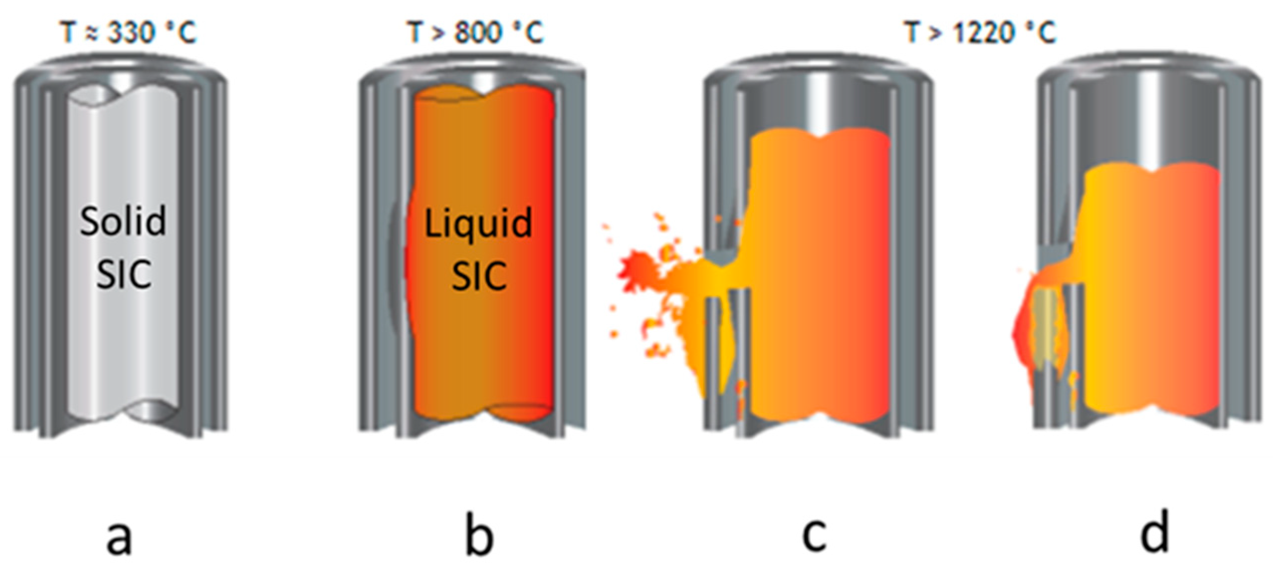
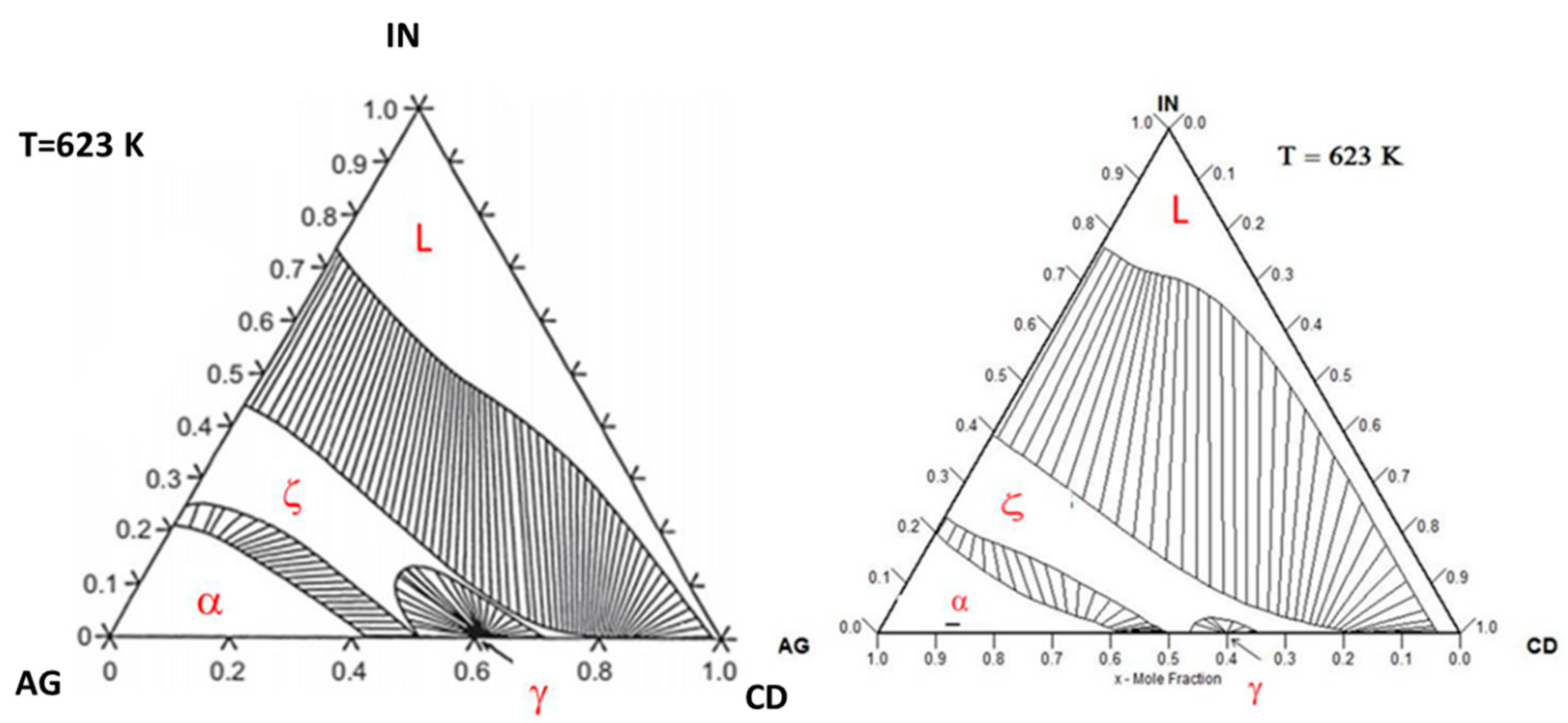
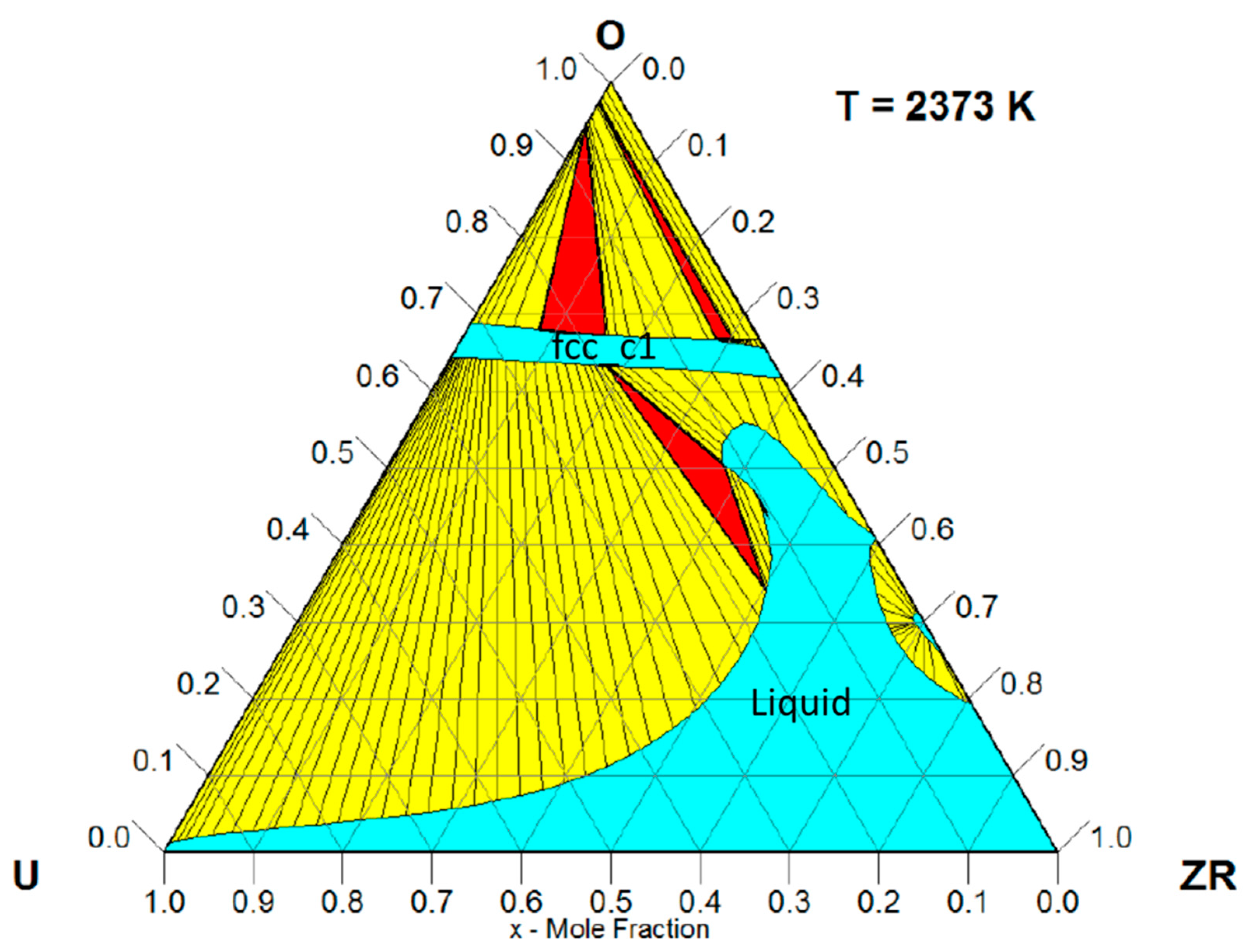
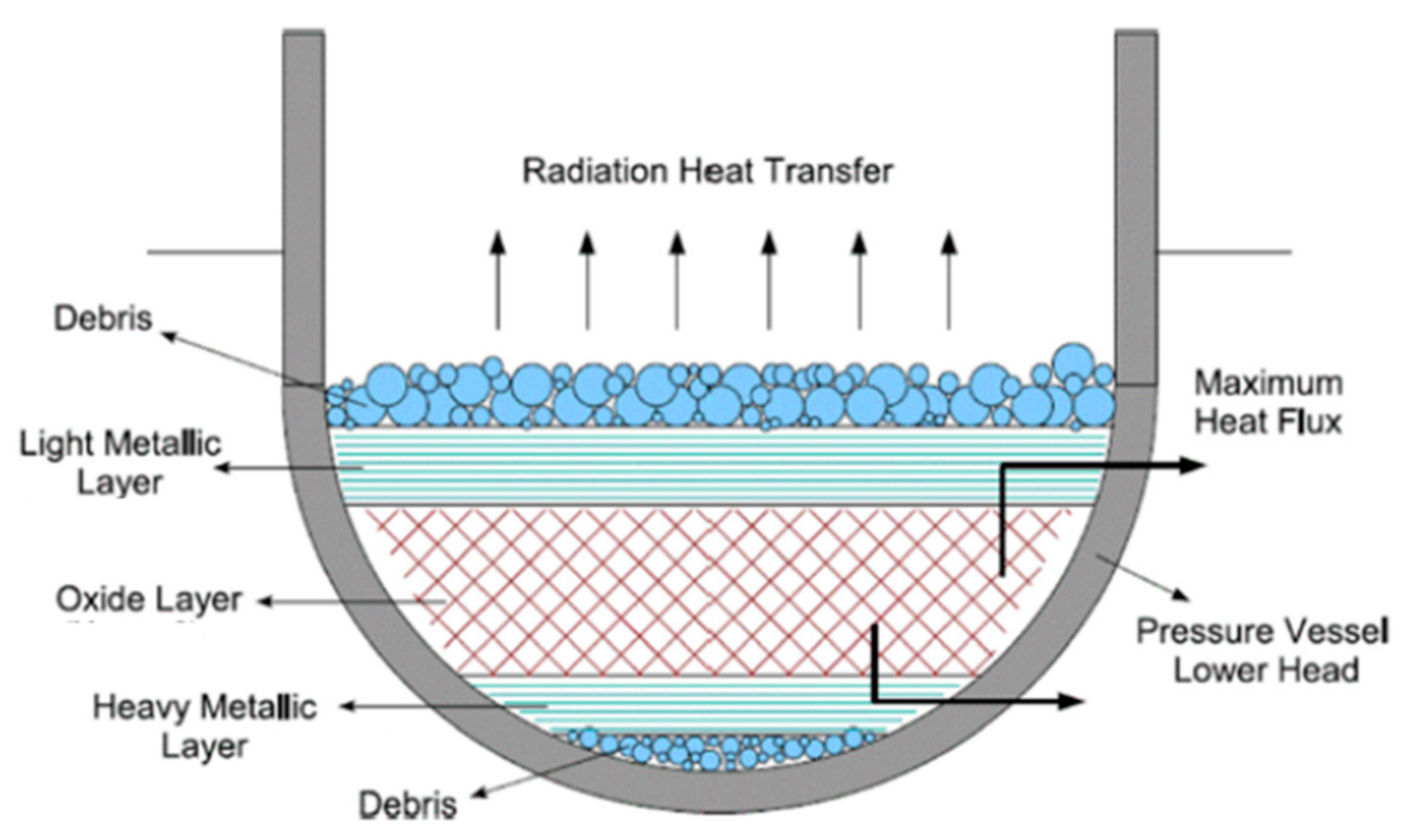
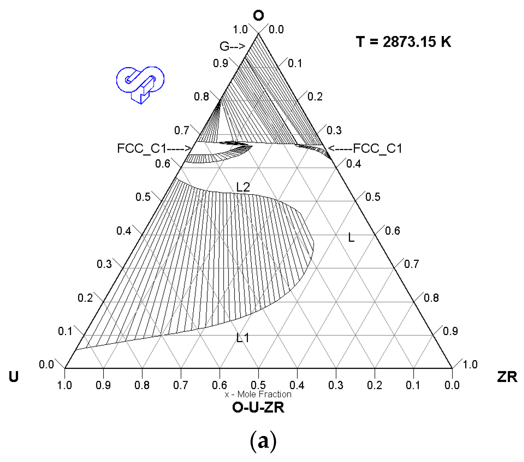
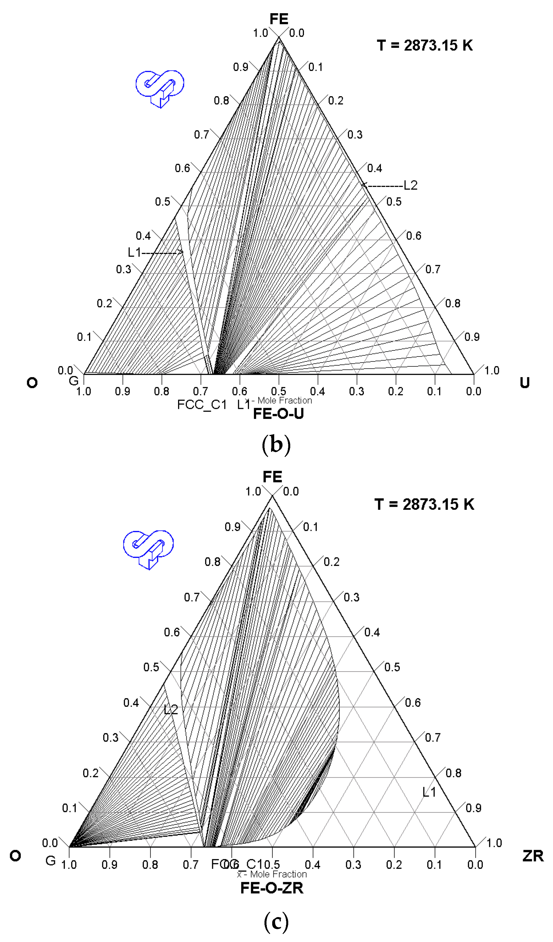
Table 1.
Main thermodynamics information in the Ag-In-Cd ternary system.
| Authors | Compositions and Temperatures | Data | Technique |
|---|---|---|---|
| Experimental Data | |||
| Snyder [48] | Rich-silver corner at 20 °C and 315 °C | Stability of the fcc solid solution | XRD (3) and metallography |
| Horrocks [46] Bowsher et al. [47] Steinbruck et al. [21] | SIC nominal composition | Melting range Liquidus temperature Melting range | DSC (2) Not reported DSC (2) |
| Horrocks [46] | Isopleth sections xIn = 0.6 and xIn/xCd = 3 | Liquidus temperature | Smith analysis technique |
| Bénigni et al. [42] | Isopleth sections xCd/xIn = 1, ¼, 1/9 and xAg/xIn = 1/4, 1/19 at 450 °C | Enthalpy of mixing of liquid | Drop calorimetry |
| Decreton [43] Gajavalli et al. [44] Fischer et al. [45] | Different compositions | Liquidus temperature | DTA (4) |
| Phase diagram modelling | |||
| Horrocks [46] Desgranges [49] Fischer et al. [45] | All temperatures and compositions | Gibbs energy of all phases (1) | Modelling |
Table 2.
More recent thermodynamic data related to the O-U-Zr ternary system at high temperature.
| Authors | Year | Compositions and Temperatures | Data | Technique |
|---|---|---|---|---|
| Experimental data related to the UO2-ZrO2-Zr composition domain | ||||
| Farmer et al. [64,65] | 1998 | UO2-ZrO2-Zr compositions with x(O) > 50 mol% | Solidus/liquidus temperatures | DTA (2) |
| Asmolov et al. [66,67,68,69] | 2001–2004 | UO2-ZrO2-Zr compositions with x(O) > 50 mol% | Liquidus temperatures | Visual technique |
| Khabensky et al. [70] | 2006 | UO2-ZrO2-Zr compositions | Solidus/liquidus temperatures | VPA (1) and DTA (2) |
| Bottomley et al. [71] | 2008 | UO2-ZrO2-Zr compositions | Liquidus temperatures | Thermal arrest |
| Quaini et al. [63] | 2018 | Miscibility gap at liquid state, 2294 °C | Tie-lines | Equilibrium + quenching |
| Hayward et al. [72,73] | 1996 | UO2-ZrO2-Zr compositions, 2000–2500 °C | Liquidus | Indirect determination based on dissolution kinetics change |
| Hofmann et al. [74,75,76] | 1997 | UO2-ZrO2-Zr compositions with x(O) > 50 mol% | Liquidus | Indirect determination based on dissolution kinetics change |
| Almjashev et al. [77] | 2021 | Miscibility gap at liquid state | Tie-lines | Equilibrium + quenching |
| Bechta et al. [78] | 2008 | Miscibility gap at liquid state, 2370 °C, 2480 °C | Tie-lines | Equilibrium + quenching |
| Guéneau et al. [79] | 1998 | Miscibility gap at liquid state, 2950 °C | Tie-lines | Equilibrium + quenching |
| Experimental data related to the UO2-ZrO2-O2 composition domain | ||||
| Ronchi et al. [80] | 2002 | UO2-ZrO2 | Solidus temperatures | Thermal arrest |
| Punni et al. [81] | 2001 | UO2-ZrO2-(O2) | Solidus/liquidus temperatures | Thermal arrest |
| Manara et al. [82] | 2008 | UO2-ZrO2 | Solidus/liquidus temperatures | Thermal arrest |
| Mastromarino et al. [83] | 2017 | UO2-ZrO2-O2 | Solidus/liquidus temperatures | Thermal arrest |
| Phase diagram modelling | ||||
| P.Y. Chevalier et al. [19,62] A. Quaini et al. [63] | 2004–2008 2018 | All temperatures and compositions | Gibbs energy of all phases (1) | Modelling |
(1) VPA: visual polythermal analysis (2) DTA: differential thermal analysis.
Table 3.
More recent experimental data related to the O-U-Zr-Fe(steel) system at high temperature in the metal-oxide composition range. (*) r = mass of iron/(mass of iron + mass of U-Zr-O).
Table 3.
More recent experimental data related to the O-U-Zr-Fe(steel) system at high temperature in the metal-oxide composition range. (*) r = mass of iron/(mass of iron + mass of U-Zr-O).
| Authors | Compositions and Temperatures | Data | Technique | |
|---|---|---|---|---|
| MASCA1 and 2 Projects PWR Tests U/Zr = 1.2 | ||||
| U-O-Zr-Fe (2500 °C–2600 °C) | ||||
| Cn | r (*) | |||
| 32 | 0–29 | Composition of metal and oxide phases | Equilibrium + quenching in cold crucible | |
| 50 | 2.0 | |||
| 70 | 2–10 | |||
| 100 | 2.0 | |||
| U-O-Zr-Steel | ||||
| 32 | 9.1 | |||
| MASCA1 and 2 Projects BWR Tests U/Zr = 0.9 | ||||
| U-O-Zr-Fe (2500 °C–2600 °C) | ||||
| 32 | 0–20 | Composition of metal and oxide phases | Equilibrium + quenching in cold crucible | |
Table 4.
Corium–siliceous concrete compositions and measured solidus and liquidus temperatures [143].
Table 4.
Corium–siliceous concrete compositions and measured solidus and liquidus temperatures [143].
| Composition (wt. %) | Solidus (°C) | Liquidus (°C) | |||||||
|---|---|---|---|---|---|---|---|---|---|
| UO2 | ZrO2 | CaO | SiO2 | Al2O3 | MgO | Fe2O3 | |||
| Concrete (80%)–Corium (20%) | 15.6 | 4.4 | 12.0 | 62.4 | 4.0 | 0.8 | 0.8 | - | 2170 |
| Concrete (27.5%)–Corium (72.5%) | 56.5 | 16.0 | 4.1 | 21.5 | 1.4 | 0.275 | 0.275 | 1134–1322 | 2094/2276 |
| Concrete (10%)–Corium (90%) | 70.2 | 19.8 | 1.5 | 7.8 | 0.5 | 0.1 | 0.1 | 1610 | - |
| Corium (100%) | 78.0 | 22.0 | - | - | - | - | - | - | - |
Table 5.
Corium–limestone concrete compositions and measured solidus and liquidus temperatures [143,144].
| Composition (wt. %) | Solidus (°C) | Liquidus (°C) | |||||||
|---|---|---|---|---|---|---|---|---|---|
| UO2 | ZrO2 | CaO | SiO2 | Al2O3 | MgO | Fe2O3 | |||
| Roche et al. [143] | |||||||||
| Concrete (60%)–Corium (40%) | 31.2 | 8.8 | 42.6 | 7.2 | 1.8 | 7.8 | 0.6 | 1300 | > 2577 |
| Concrete (36.2%)–Corium (63.8%) | 49.8 | 14.0 | 25.7 | 4.3 | 1.1 | 4.7 | 0.4 | - | > 2577 |
| Concrete (27.5%)–Corium (72.5%) | 56.6 | 15.9 | 19.5 | 3.3 | 0.8 | 3.6 | 0.3 | 1247 | > 2577 |
| Concrete (10%)–Corium (90%) | 70.2 | 19.8 | 7.1 | 1.2 | 0.3 | 1.3 | 0.1 | 1615 | - |
| Hellmann et al. [144] | |||||||||
| Enthalpy n°8 | 61.9 | 14.9 | 23.2 | - | - | - | - | 1865 ± 5 | 1935 ± 45 |
| Enthalpy n°4 | 33.6 | 13.5 | 26.4 | - | 26.5 | - | - | 1340 ± 20 | 1760 ± 20 |
Table 6.
Corium–“limestone common sand concrete” compositions and measured solidus and liquidus temperatures [143,144].
| Composition (wt. %) | Solidus (°C) | Liquidus (°C) | |||||||
|---|---|---|---|---|---|---|---|---|---|
| UO2 | ZrO2 | CaO | SiO2 | Al2O3 | MgO | Fe2O3 | |||
| Roche et al. [143] | |||||||||
| Corium 1 | 92.0 | 8.0 | - | - | - | - | - | - | - |
| Concrete (60.4%)–Corium 1 (39.6%) | 36.4 | 3.2 | 23.0 | 24.8 | 3.0 | 8.4 | 1.2 | - | > 2304 |
| Concrete (47%)–Corium 1 (53%) | 48.8 | 4.2 | 17.9 | 19.3 | 2.3 | 6.6 | 0.9 | 1175 | > 2450 |
| Corium 2 | 78.0 | 22.0 | - | - | - | - | - | - | - |
| Concrete (80%)–Corium 2 (20%) | 15.6 | 4.4 | 30.4 | 32.8 | 4.0 | 11.2 | 1.6 | 1245 | - |
| Concrete (27.5%)–Corium 2 (72.5%) | 56.5 | 16.0 | 10.4 | 11.3 | 1.4 | 3.9 | 0.5 | 1087 | 2365/2577 |
| Concrete (10%)–Corium 2 (90%) | 70.2 | 19.8 | 3.8 | 4.1 | 0.5 | 1.4 | 0.2 | 1575 | - |
| Hellmann et al. [144] | |||||||||
| Enthalpy n°9 | 31.5 | 9.5 | 33.5 | 25.5 | - | - | - | 1490 ± 30 | 1630–1830 |
Publisher’s Note: MDPI stays neutral with regard to jurisdictional claims in published maps and institutional affiliations. |
© 2021 by the author. Licensee MDPI, Basel, Switzerland. This article is an open access article distributed under the terms and conditions of the Creative Commons Attribution (CC BY) license (https://creativecommons.org/licenses/by/4.0/).
Share and Cite
MDPI and ACS Style
Barrachin, M. Corium Experimental Thermodynamics: A Review and Some Perspectives. Thermo 2021, 1, 179-204. https://0-doi-org.brum.beds.ac.uk/10.3390/thermo1020013
AMA Style
Barrachin M. Corium Experimental Thermodynamics: A Review and Some Perspectives. Thermo. 2021; 1(2):179-204. https://0-doi-org.brum.beds.ac.uk/10.3390/thermo1020013
Chicago/Turabian StyleBarrachin, Marc. 2021. "Corium Experimental Thermodynamics: A Review and Some Perspectives" Thermo 1, no. 2: 179-204. https://0-doi-org.brum.beds.ac.uk/10.3390/thermo1020013