
Vibration of Periodic Drill-Strings with Local Sources of Resonance


1
School of Engineering and Applied Sciences, Nile University, Giza, Egypt
2
Mechanical Engineering Department, College of Science, Taif University, Taif 21974, Saudi Arabia
3
Department of Mechanical and Industrial Engineering, Qatar University, Doha 2713, Qatar
4
Mechanical Engineering Department, University of Maryland, College Park, MD 20742, USA
*
Author to whom correspondence should be addressed.
Vibration 2021, 4(3), 586-601; https://doi.org/10.3390/vibration4030034
Submission received: 15 June 2021
/
Revised: 6 July 2021
/
Accepted: 12 July 2021
/
Published: 17 July 2021
(This article belongs to the Special Issue Vibrations and Reliability)
Abstract
:A new class of drill-strings is proposed for attenuating undesirable vibrations to ensure effective operation. The drill-string is provided with passive periodic inserts, which are integrated with sources of local resonance (LR). The inserts make the drill-string act as a low frequency pass mechanical filter for the transmission of vibration along the drill-string. Proper design of the periodic inserts with sources of LR tend to shift these stop bands towards zones of lower frequencies to enable confining the dominant modes of vibration of the drill-string within these bands. In this manner, propagation of the vibration along the drill-string can be completely blocked. A finite element model (FEM) is developed using ANSYS to investigate the bandgap characteristics of the proposed drill-string with sources of LR. The developed FEM accounts for bending, torsional, and axial vibrations of the drill-string in order to demonstrate the effectiveness of the periodic inserts with LR in simultaneous control of these combined modes as compared to conventional solid periodic inserts, which are only limited to controlling bending vibrations. The effect of the design parameters of the periodic inserts with LR on the bandgap characteristics of the drill-string is investigated to establish guidelines of this class of drill-strings.
1. Introduction
Considerable attention has been devoted, during the past years, to develop a thorough understanding of the complex nature of the vibration of drill-strings to devise effective means for controlling the associated destructive effects as presented, for example, in the comprehensive account of Spanos et al. [1].
Distinct among the exerted efforts are those dealing with modeling the vibration of drill-strings under the influence of combined bending, axial, and torsional modes of vibration [2,3,4,5,6,7,8]. The developed models vary from simple continuous system models to the more complex finite element models, which are subjected to various loading and excitation conditions such as axial bit bouncing [9,10], torsional stick-slip [11,12,13,14,15], and whirl vibrations [16]. These models have been utilized and exercised to predict the time and frequency response characteristics, the stability and bifurcation analysis, the limit cycle conditions, equilibrium points, and self-excited vibration [11,12,13,14,15].
In parallel to these attempts, several passive vibration mitigation attempts have been considered to attenuate the vibration of drill-strings. Examples of these attempts include the nonlinear energy sink approach [17], the magneto-rheological damping [18], the tunable vibration absorber [19], and the anti-stalling vibration attenuation devices [20].
More advanced active vibration control approaches have also been considered including simple control [21], optimal control [22], and robust control approaches [23,24].
In all the above-described investigations, the focus has been placed on drill-strings of uniform cross sections. No effort has been exerted to depart radically to new designs such as the new class of periodic drill-strings, which have proven to be effective in minimizing the vibration transmission along the drill-strings [25,26]. Therefore, it is the purpose of this paper is to extend the work of Alsaffar et al. [25,26] on periodic drill-stings by introducing a new class of drill-strings with periodic inserts provided with sources of local resonance (LR), to extend the bandgap characteristics to low operating frequencies and lower operating speeds. The emphasis will be placed on developing a finite element model (FEM) of this new class of drill-strings to account for the simultaneous bending, torsional, and axial vibrations. The FEM is intended to demonstrate the effectiveness of the periodic inserts with LR in simultaneous control of these combined modes of vibrations as compared to conventional solid periodic inserts, which are only limited to controlling bending vibrations. The effect of the various design parameters of the periodic inserts with LR on the bandgap characteristics of the drill-string is investigated in an attempt to establish design guidelines of this new class of drill-strings.
2. Concept of the Periodic Drill-Strings with Local Sources of Resonance
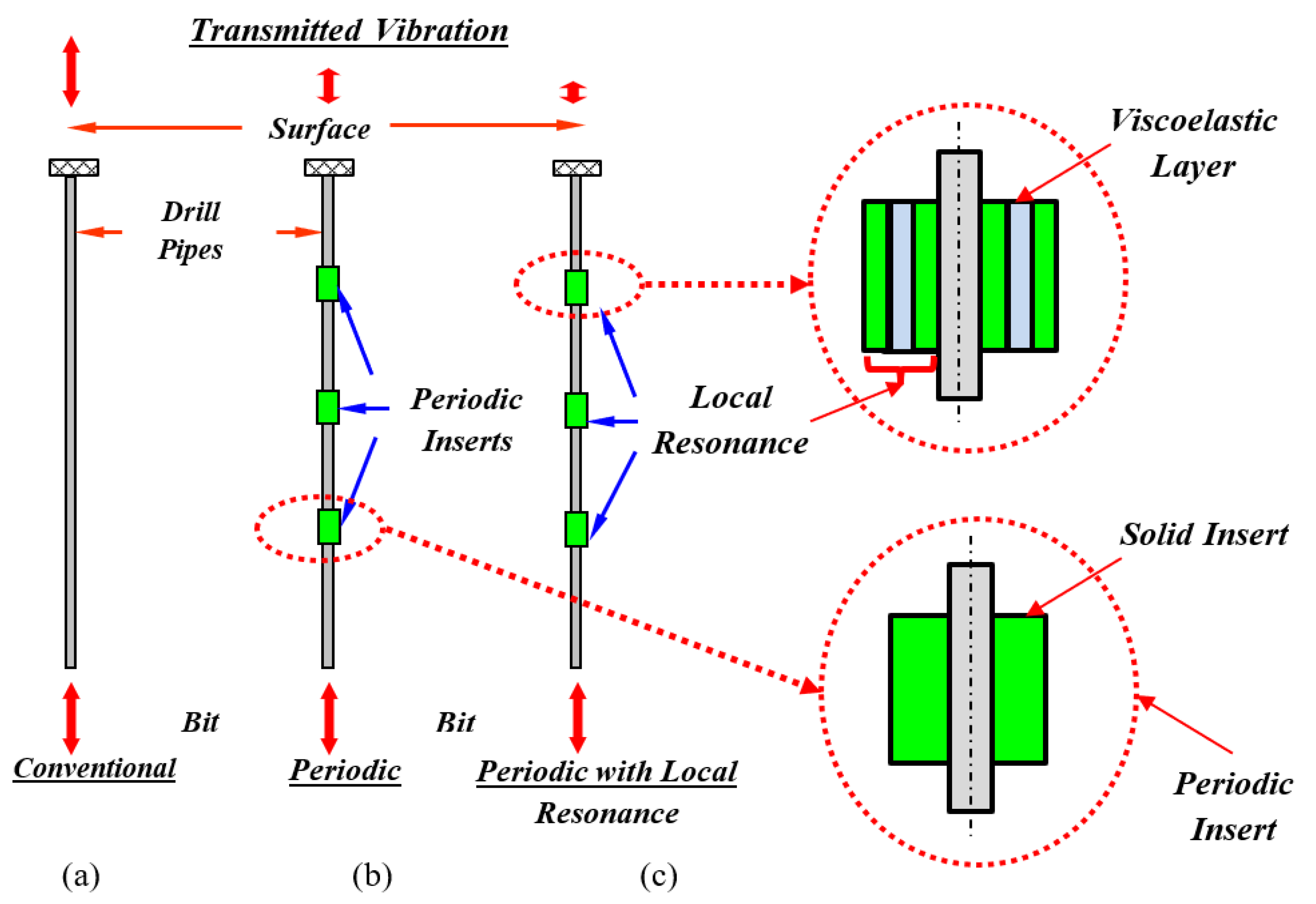
The concept of conventional periodic drill-string can best be illustrated by considering the schematic drawings displayed in Figure 1. The conventional drill-string shown in Figure 1a, is provided with optimally designed passive and solid periodic inserts. The inserts generate sources of impedance mismatch along the vibration transmission path. Hence, the wave propagation can be altered through the insertion of geometrical or material discontinuities, as shown in Figure 1b.
In the passive periodic drill-strings, the design and the location of the inserts are selected properly to confine the dominant modes of vibration of the drill-string within the stop bands generated by the periodic arrangement of the inserts. This concept has been successfully investigated and demonstrated by Alsaffar et al. [25,26]. It is important to note that the concept and filtering characteristics of periodic drill-string is particularly suitable for mitigating and blocking the vibration over a wide range of drilling depths. The operating principle of this type of drill-strings is deep rooted in the theory of periodic structures, which renders these structures to act as mechanical filters [27,28,29,30].
A promising new design direction would be achieved by augmenting the periodic drill-string with “local resonance” capabilities in order to extend its “stop band” characteristics to low frequency zones. Such capabilities will enable operating the drill-strings at low speeds, which in turn will result in reducing the induced vibrations. This class of periodic drill-strings will consist of a conventional drill-string with periodic inserts that have cavities which house resonating masses connected to the cavity wall by springs and dampers. The macroscopic dynamical properties of the resulting periodic drill-strings depend on the resonant properties of substructures that contribute to the rise of interesting effects such as broad stop band characteristics, which can be adjusted by tuning of the local resonance sources. Figure 1c shows typical schematic drawings of a drill-string structure with periodic inserts fitted with local sources of resonances.
The potential application spectrum of the proposed new class of periodic drill-strings is envisioned to be beneficial to improving the quality and the state-of-the-art of drilling operations both in land and in sea. Furthermore, this spectrum is only limited by our imagination.
Figure 1c shows a special class of periodic structures with local sources of resonances. This class of structures has been introduced due to its unusual response to elastic wave propagation as has been recently reported [31,32].
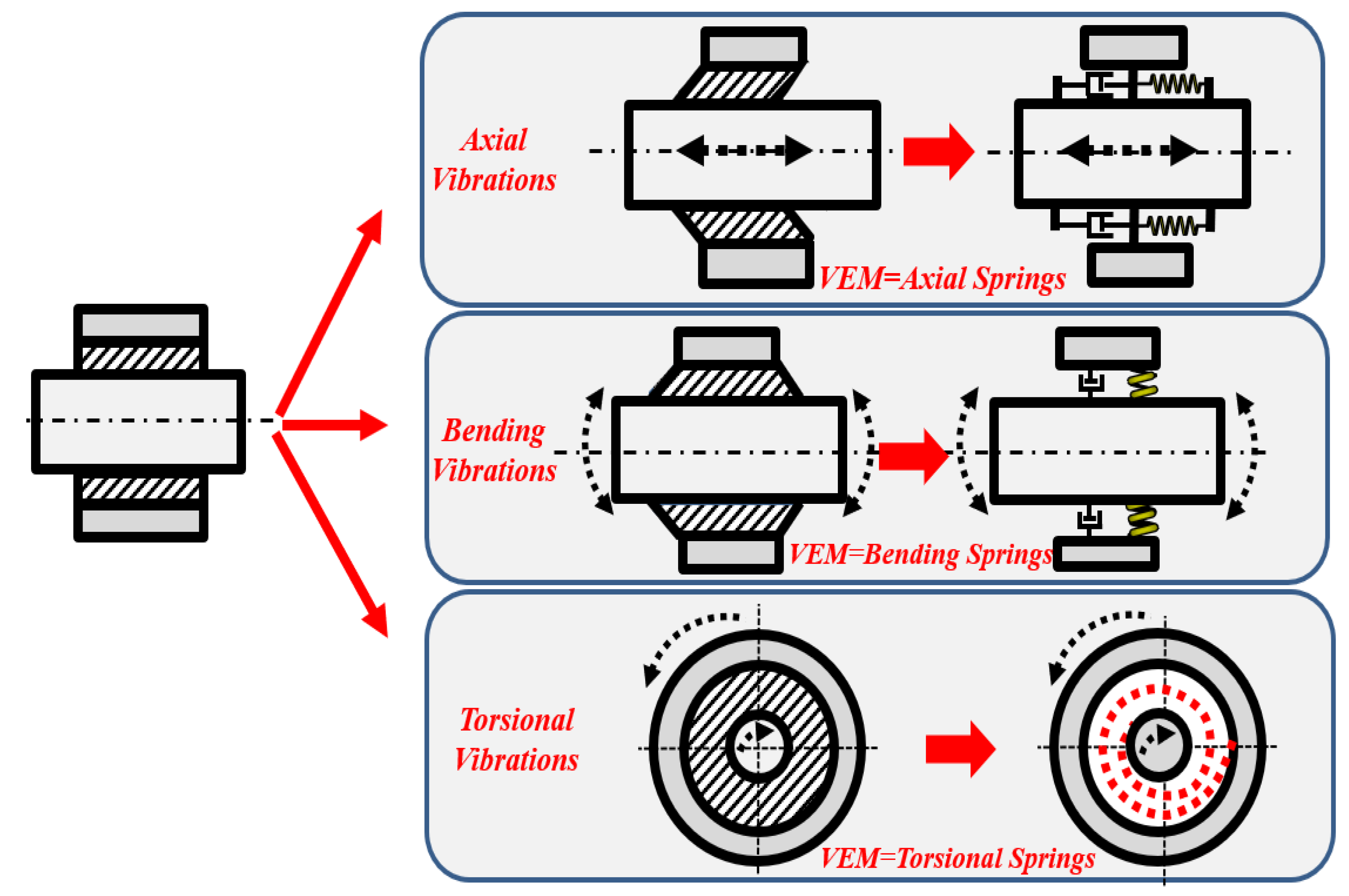
Periodic inserts with local resonant sources provide the ability of simultaneous control of the torsional, axial, and transverse bending vibrations, as indicated in Figure 2. Accordingly, such strategy enables a comprehensive mitigation of the vibration of the drill-strings in a passive manner.
3. Materials and Methods
The concept and filtering characteristics of the different configurations of periodic drill-string, that enables the mitigation and blockage of the vibration over a wide range of drilling depths, can best be understood by considering the conceptual characteristics displayed in Figure 1 and Figure 2.
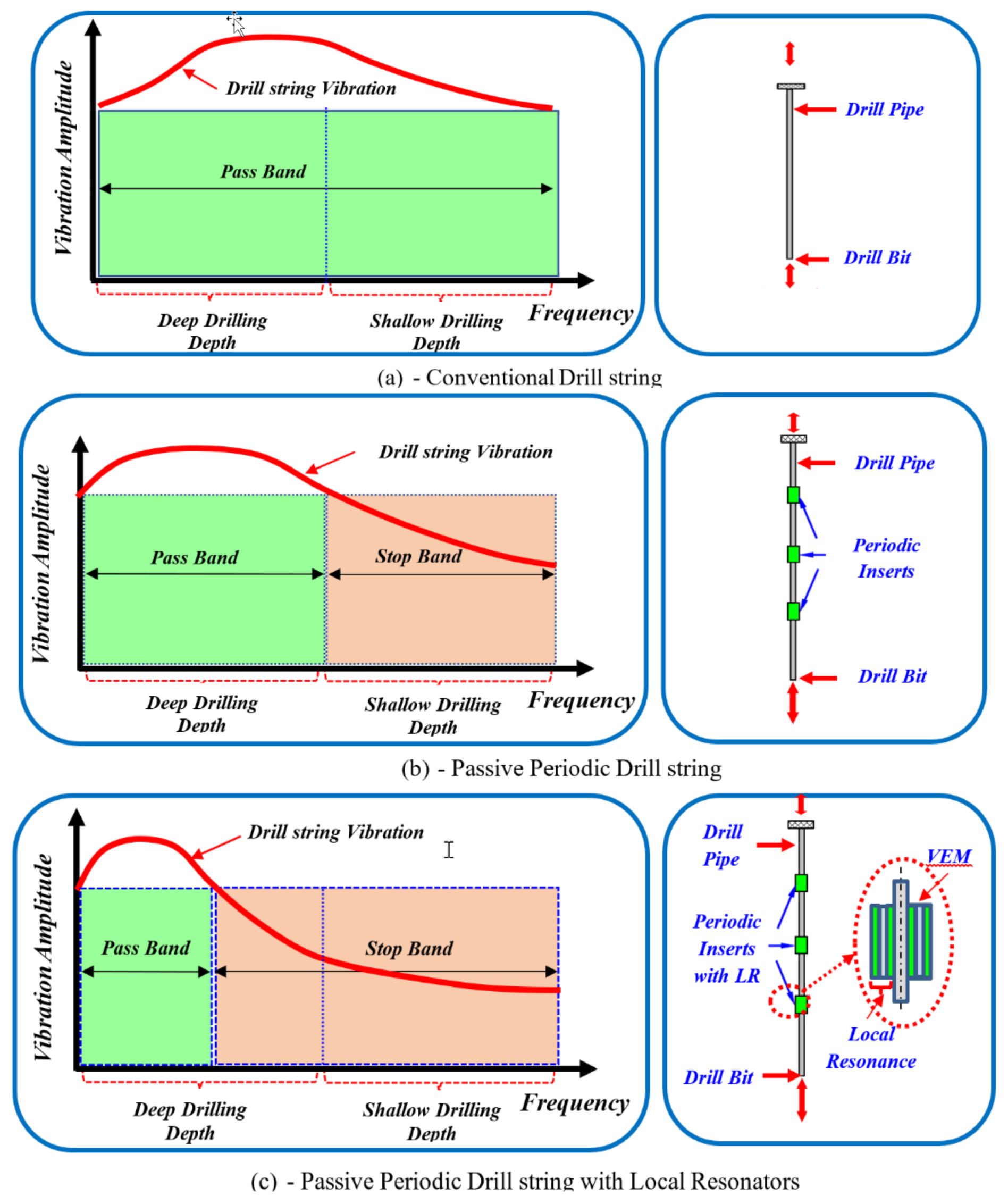
These characteristics are distinguished from those of conventional drill-strings, which experience excessive vibration over the entire operating envelope of rotational speeds and drilling depths, as shown in Figure 3a. In this case, the drill-string acts as a pass filter that transmits the vibration completely from the drill bit end to the surface end.
However, when the drill-string is provided with passive periodic inserts, it may experience the characteristics shown in Figure 3b. These characteristics indicate that, at shallow drilling depth, the drill-string can typically have a dominant natural frequency or operating speed, which can be ensured to lie within the stop band of a properly designed bandgap characteristic of the periodic inserts. However, as the drilling depth increases, the drill-string becomes longer and softer, and its vibration is more likely to be with higher amplitudes since the dominant natural frequency or operating speed will no longer lie inside the possible achievable bounds of the stop band of passive periodic inserts.
Therefore, an alternative approach is needed whereby the periodic inserts are augmented with sources of local resonance. These modified inserts expand the stop band as shown in Figure 3c to lower frequencies [31,32], enabling the corresponding dominant natural frequency to be confined within the expanded stop band. Thus, the expected severe vibrations can be completely blocked.
4. Parameters of Considered Drill-String
The drill-string model considered by Khulief et al. [8,15] has the characteristics listed in Table 1.
Table 2 lists the main physical and geometrical parameters of the periodic inserts and Table 3 displays the corresponding values of the parameters of the inserts with the sources of local resonance.
In Table 4, the properties of the considered VEM intermediate layer are included.
5. The Finite Element Model
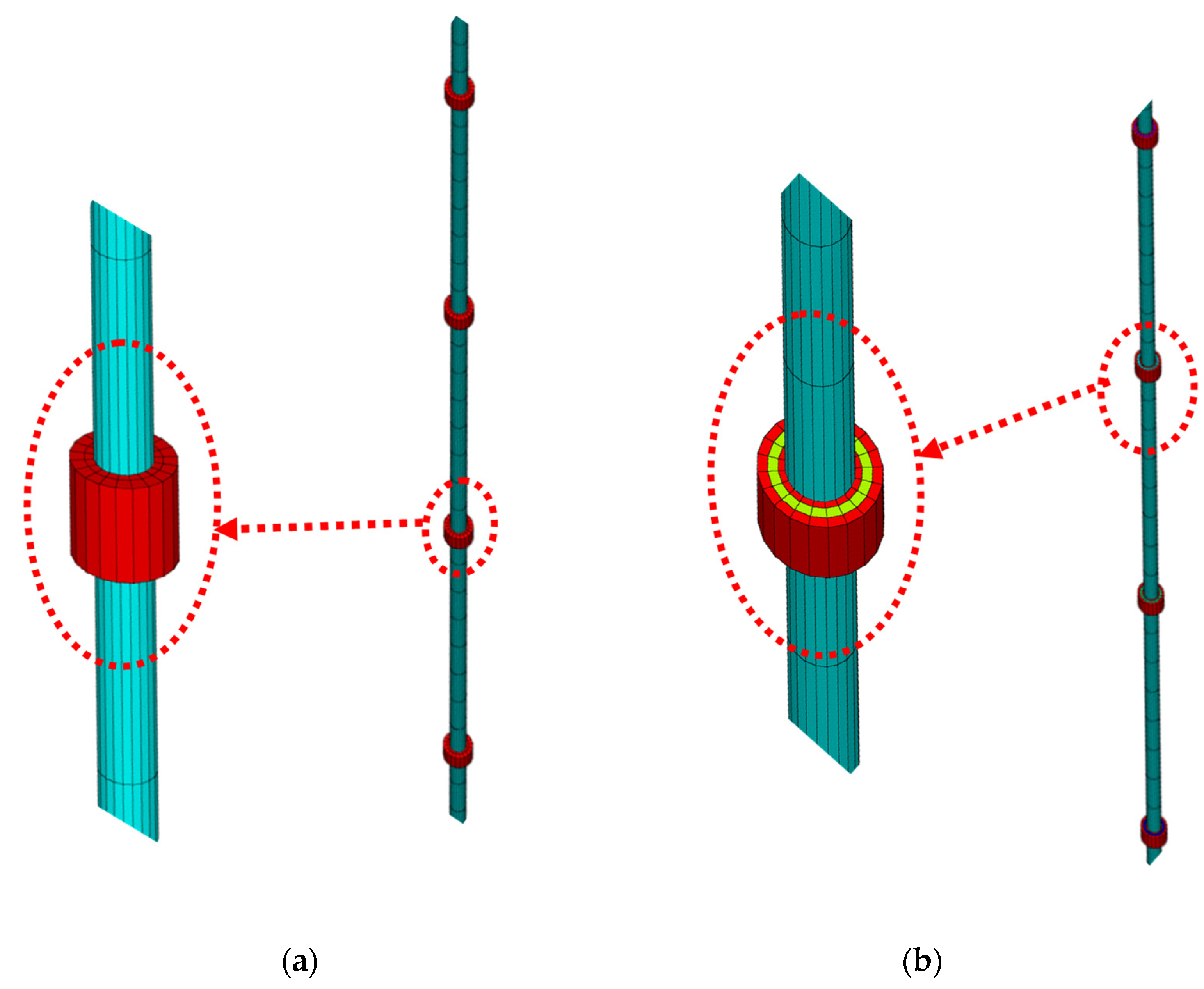
The finite element model, developed using ANSYS for the drill-string, consists of two types of elements. The first element type is beam elements BEAM188 (3D, 2-Node element) with six degrees of freedom per node (ux, uy, uz, θx, θy, θz). This type of element is one of ANSYS new-technology elements, in which arbitrary cross sections can be assigned. The beam elements were used to model the drill-pipe and the drill-collar. In the current case, the cross section used for both the drill-pipe and drill-collar are of an annulus with internal/external diameters of 0.095 and 0.127 m, respectively. For the drill-collar, the diameters are 0.095 and 0.235 m, respectively. The drill-pipe length was 1000 m divided into 1440 elements, while the drill-collar length was 200 m and was divided into 288 elements. The second type of element used in the finite element model is utilized for the periodic collars. These are modeled using shell elements SHELL281 (8-Node Structural Shell Elements) with six degrees of freedom per node (ux, uy, uz, θx θy θz). The shell thickness used is 0.25 m, which represents the periodic collar thickness. The collars are mounted in different periodic arrangements (60, 120, and 180 equi-spaced collars). Constraining functions are enforced in the finite element model to constrain the degrees of freedom of the inner collar radii nodes to the matching degrees of freedom of the beam nodes at that location. The rotation and translation of the entire drill-string are constrained at the two ends.
A pre-stressed sequential static-modal-harmonic analysis procedure is developed. During the first simulation phase (static analysis), the effect of gravitational force is included and the stress and strain matrices are retained for further modal-harmonic analysis. A full modal analysis is carried out to calculate the mode shapes and the natural frequencies extending to the harmonic excitation range of interest. Then, a mode-superposition harmonic analysis is carried out to calculate the dynamic response of the entire drill-string when subjected to combined the axial, bending forces, and torsional moment near the drill-bit end. This particular modeling procedure is adopted to be able to capture accurately the dynamic response of the drill-string without skipping any modes, if a stepped-sine harmonic analysis was directly implemented.
Figure 4a,b displays the finite element models of shafts with conventional periodic inserts and inserts with built-in sources of local resonance.
6. Modal Characteristics of Drill-Strings and Inserts with Local Resonance
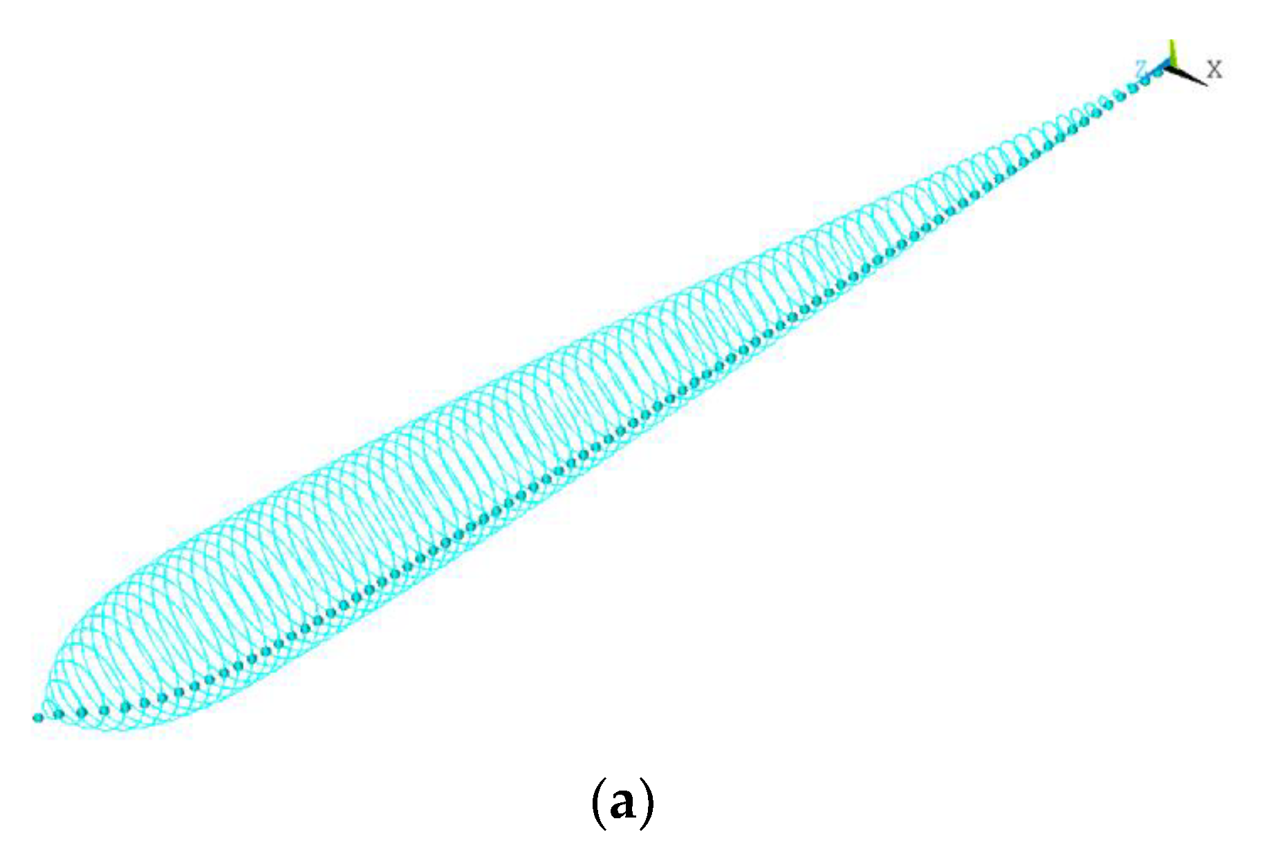
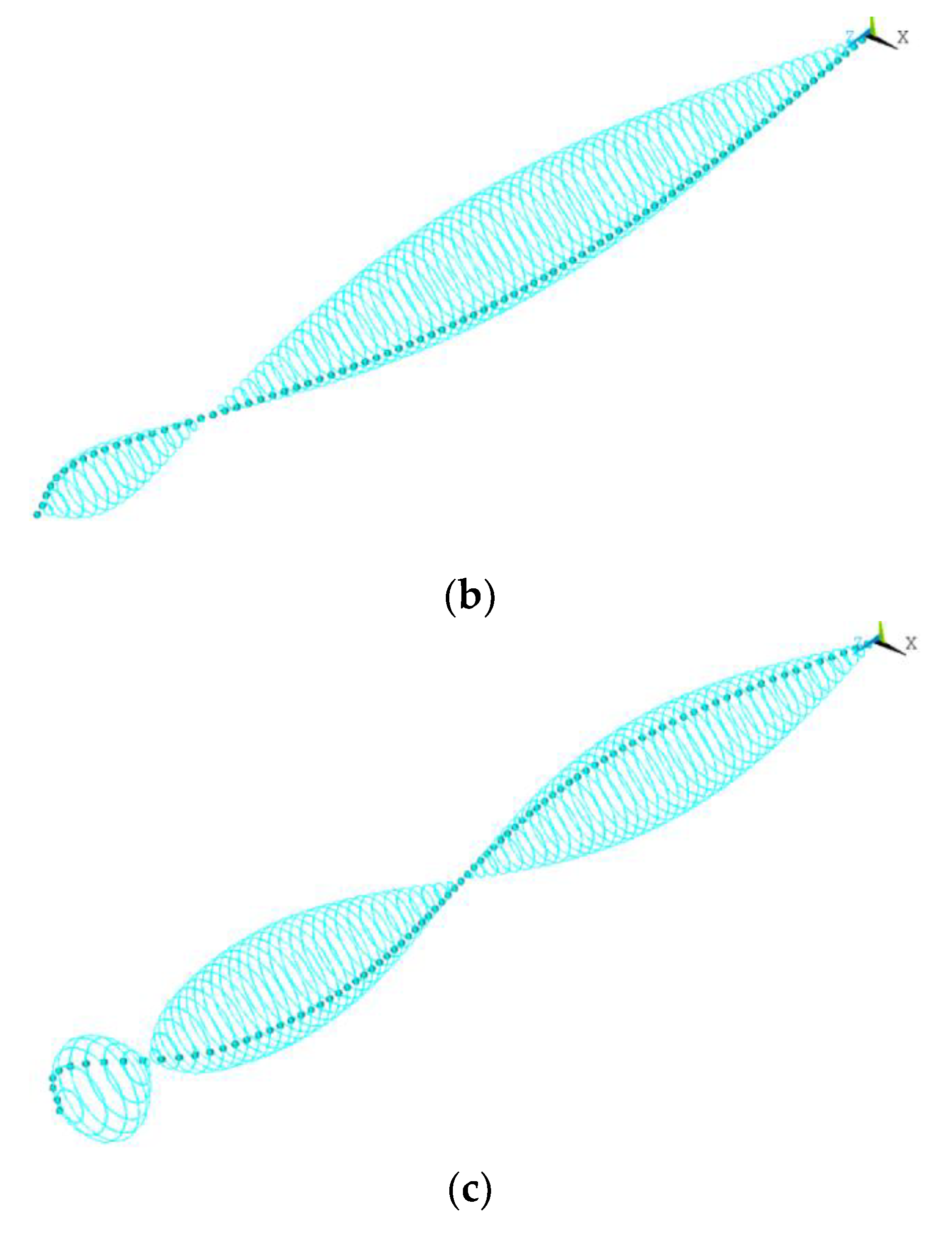
Figure 5 displays a sample of the orbits of the drill-string with uniform shaft for the first three modes of vibrations which are: 0.0325, 0.0675, and 0.111 Hz, respectively. These frequencies are in close agreement with the predictions of Khuleif et al. [8,15].
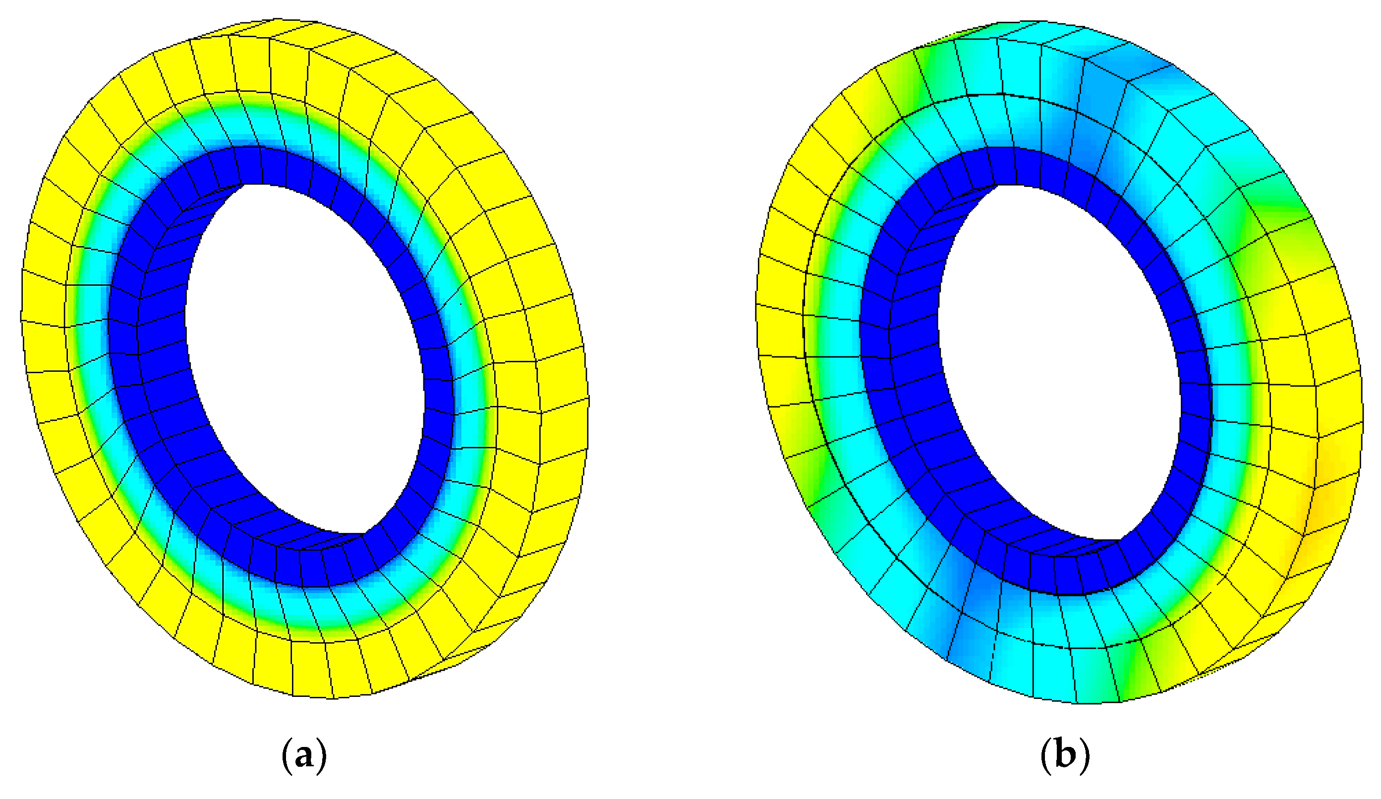
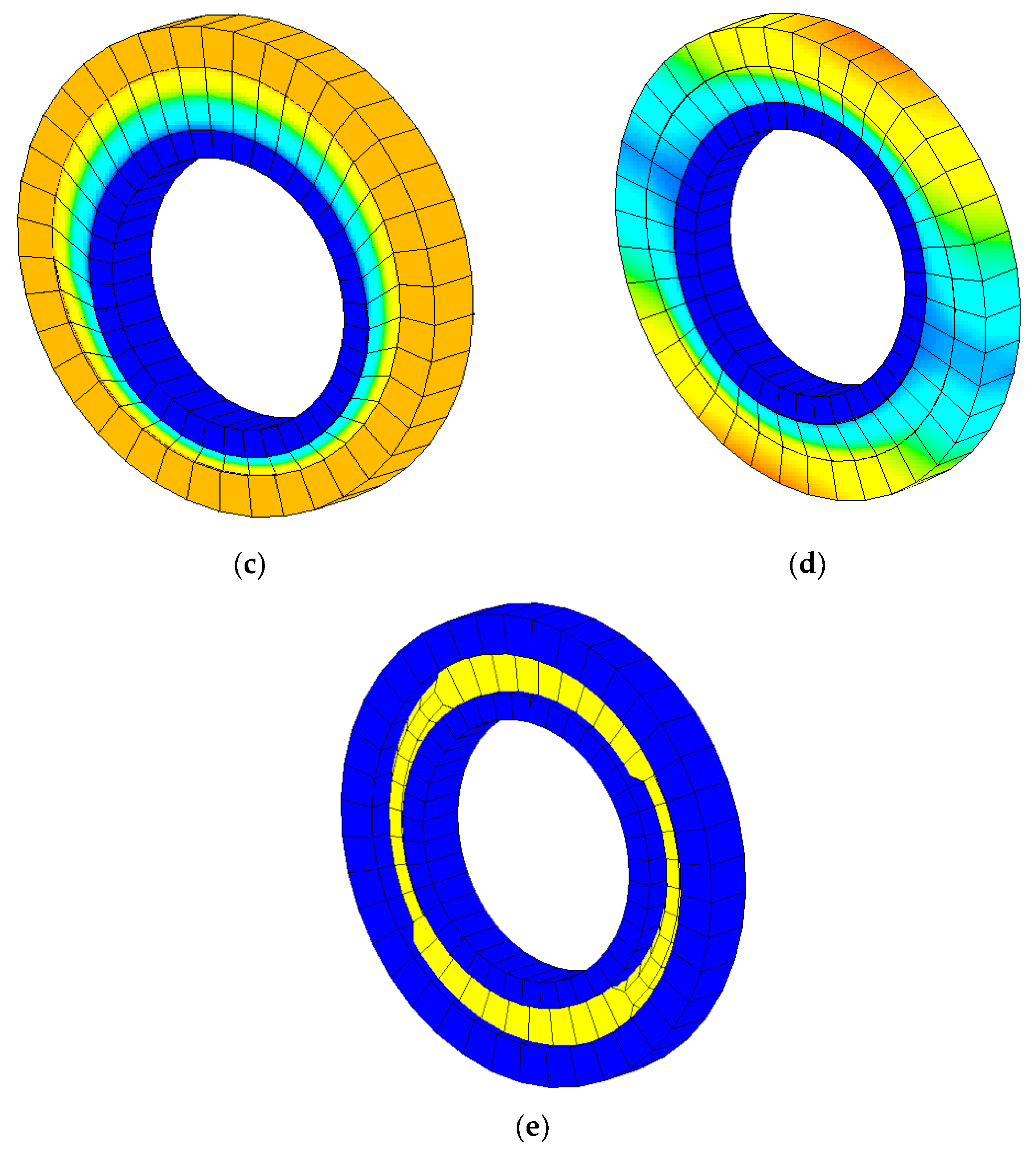
Figure 6 displays a sample of the different mode shapes of the inserts with LR. Note that these modes are much higher than those of the uniform shaft. This indicates that the local resonance of the inserts become effective in mitigating the vibration of the drill-string when the modes of the inserts coincide with those of the shaft. Under these conditions, the inserts act as local vibration absorbers.
7. Results
7.1. Dynamic Characteristics of Uniform Shaft and Shafts with Conventional Periodic Inserts
Figure 7 displays a comparison between the frequency response characteristics of a conventional drill-string and a drill-string with 60 passive periodic inserts. The figure shows the simultaneous performance characteristics of the drill-strings in the torsional, axial, and transverse directions.
It can be seen that the passive periodic inserts are effective in generating stop bands only in the transverse directions. These stop bands extend to frequencies as low as 5 Hz. However, the inserts are totally ineffective in mitigating the vibration in both the axial and torsional directions.
Figure 8 displays the corresponding comparisons between the frequency response characteristics of a conventional drill-string and a drill-string with 120 passive periodic inserts. Moreover, Figure 9 shows the comparisons when the drill-string is provided with 180 passive periodic inserts.
Figure 7, Figure 8 and Figure 9 suggest that increasing the number of the passive periodic inserts results in clearly defining the zones of the stop bands and in increasing the spectral width of these stop bands.
Figure 10 summarizes the effect of the number of periodic inserts on the spectral width of the different transverse stop bands of a passive periodic drill-string, as displayed in Figure 7, Figure 8 and Figure 9. The distinct feature of the displayed stop bands is that these bands are spectrally very narrow to be effective in controlling the drill-string vibration over a wide range of operating conditions. Furthermore, the width of these bands is almost insensitive to the increased number of inserts.
7.2. Dynamic Characteristics of Uniform Shaft and Shafts with Periodic Local Sources of Resonance
It can be seen that the periodic inserts with LR resonance are now effective in generating stop bands in the torsional direction. These stop bands extend to frequencies as low as 5 Hz when the storage modulus of the VEM is as low as 15 KPa. However, the stop band location and spectral width increase as the storage modulus of the VEM increases.
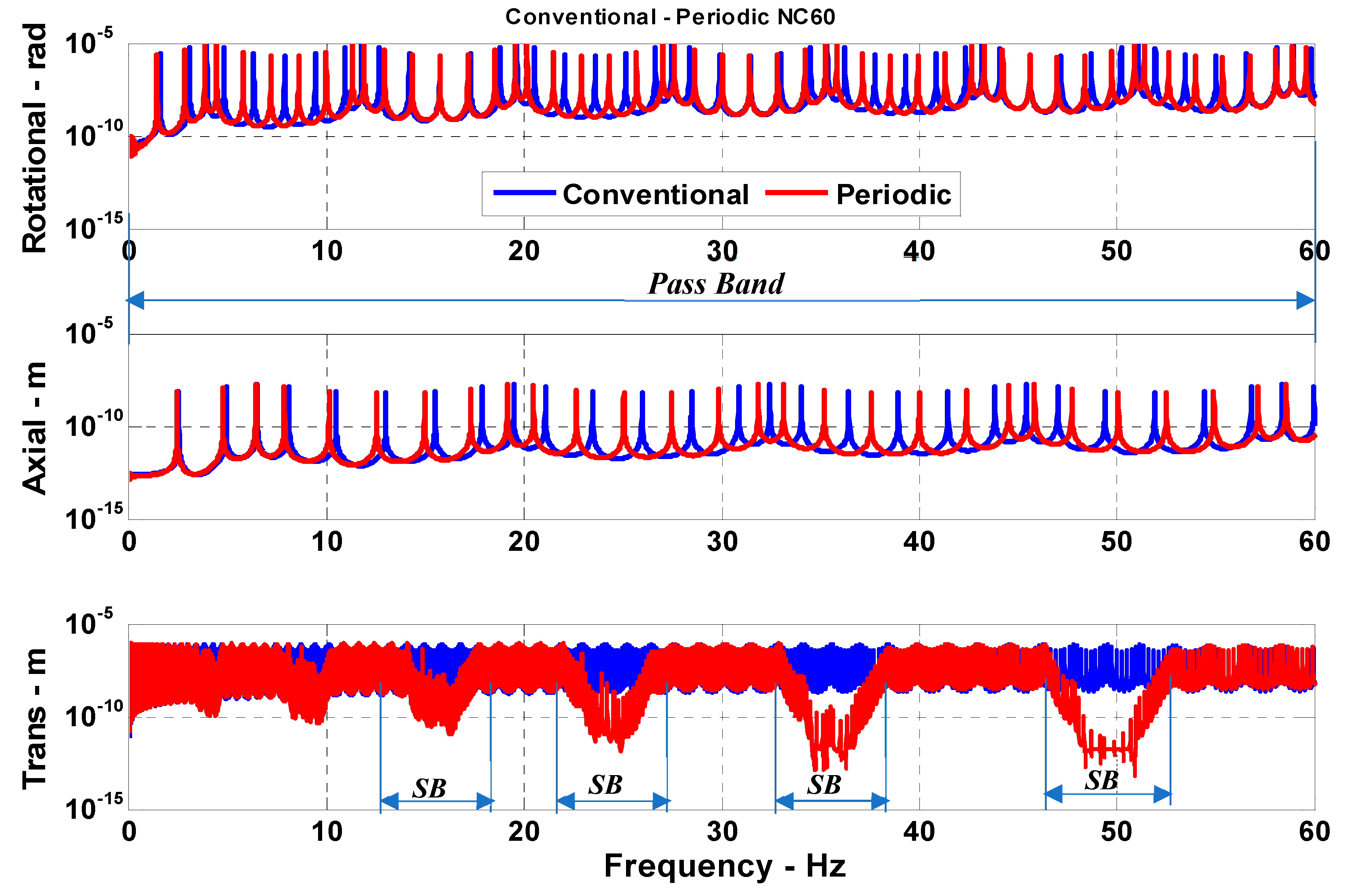
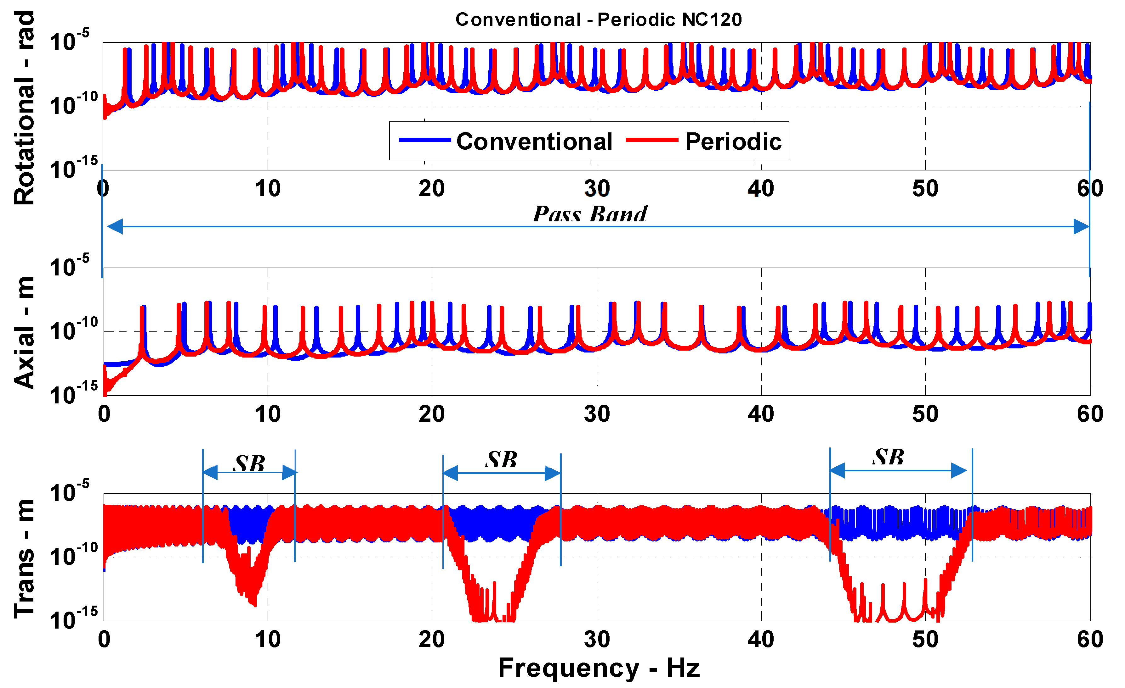
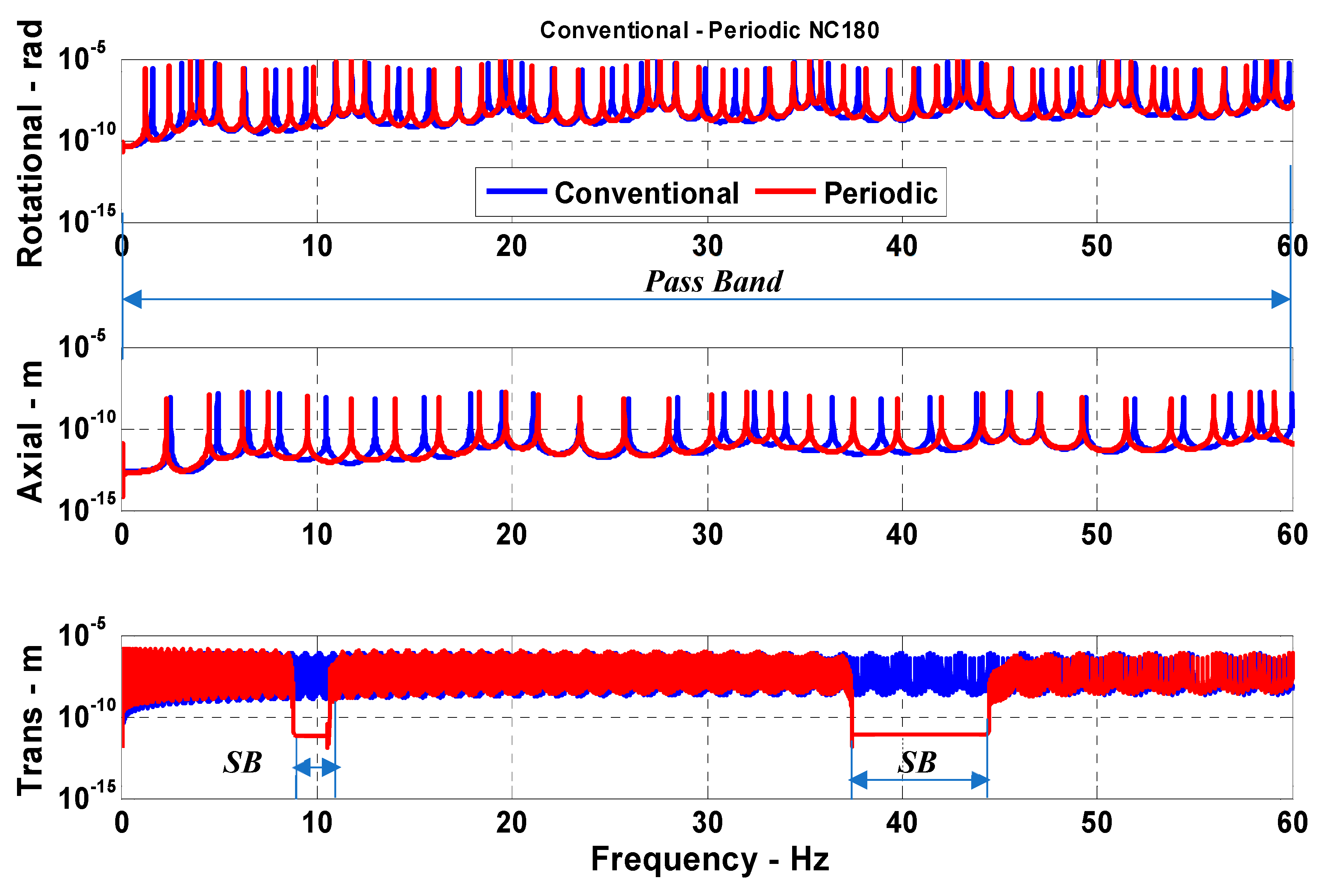
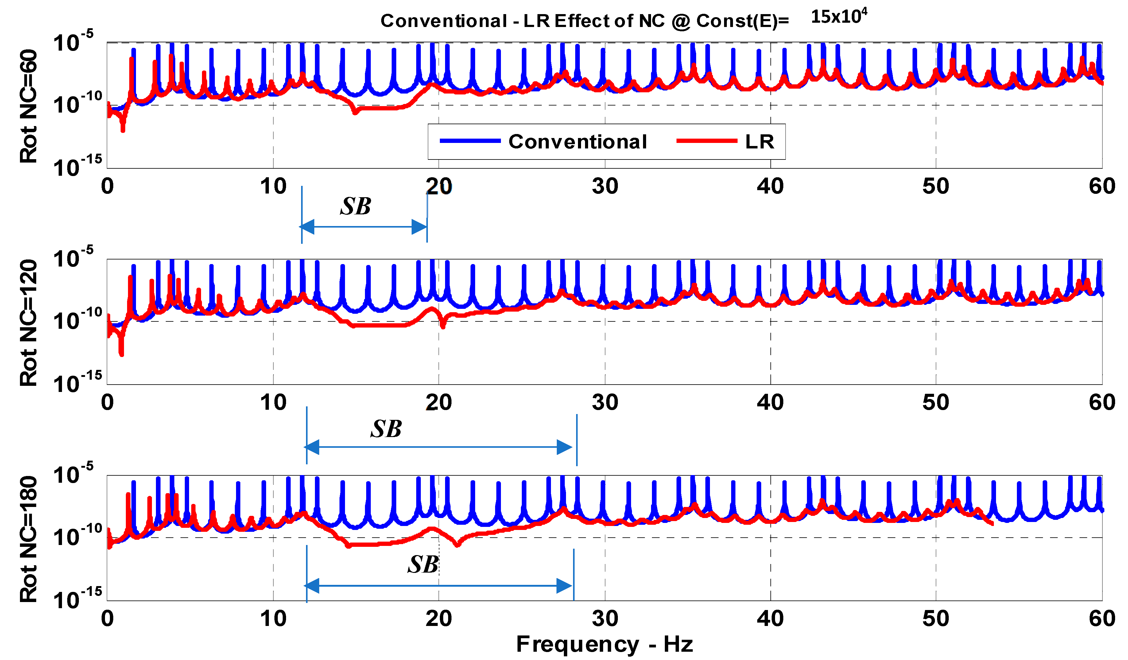
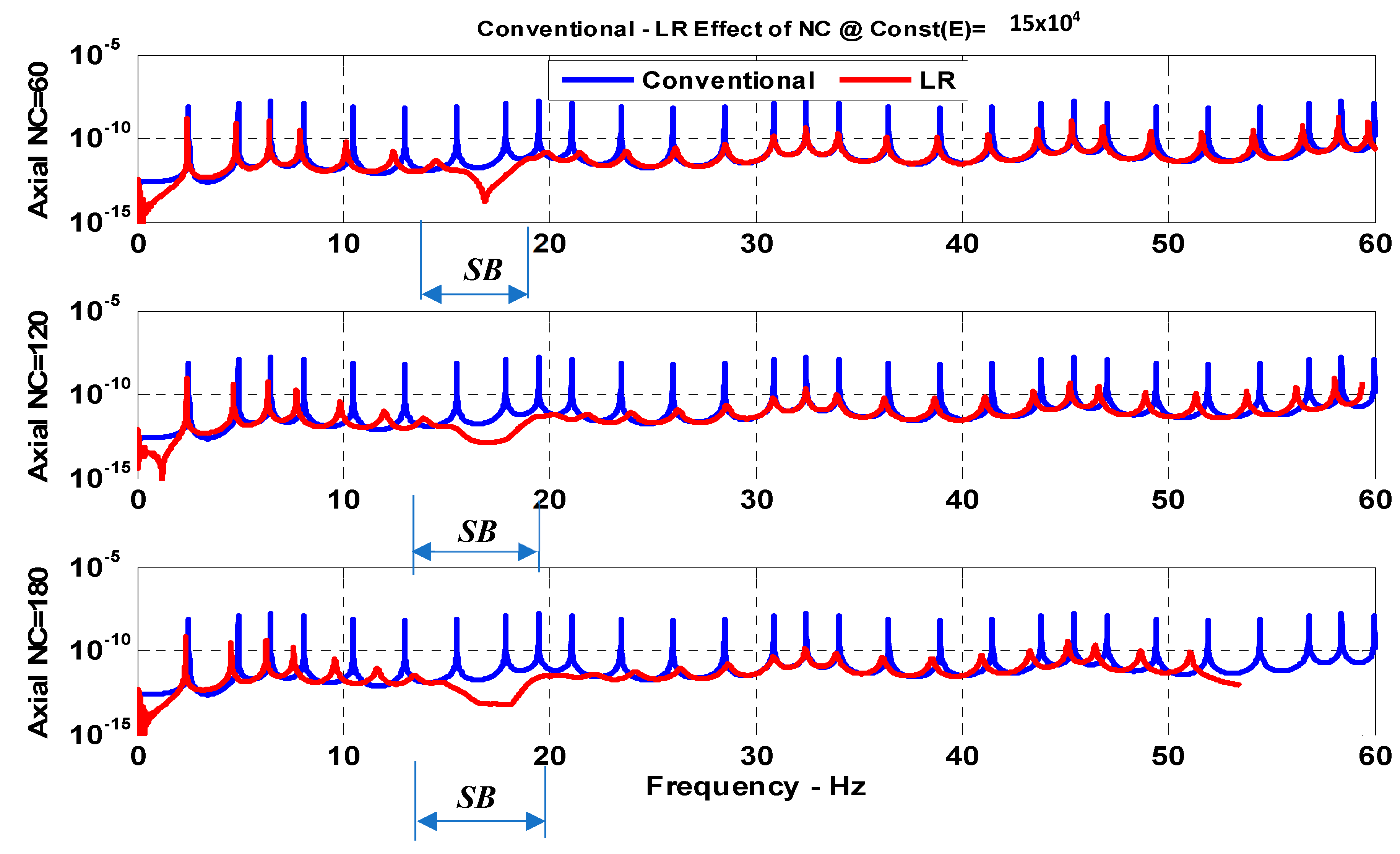
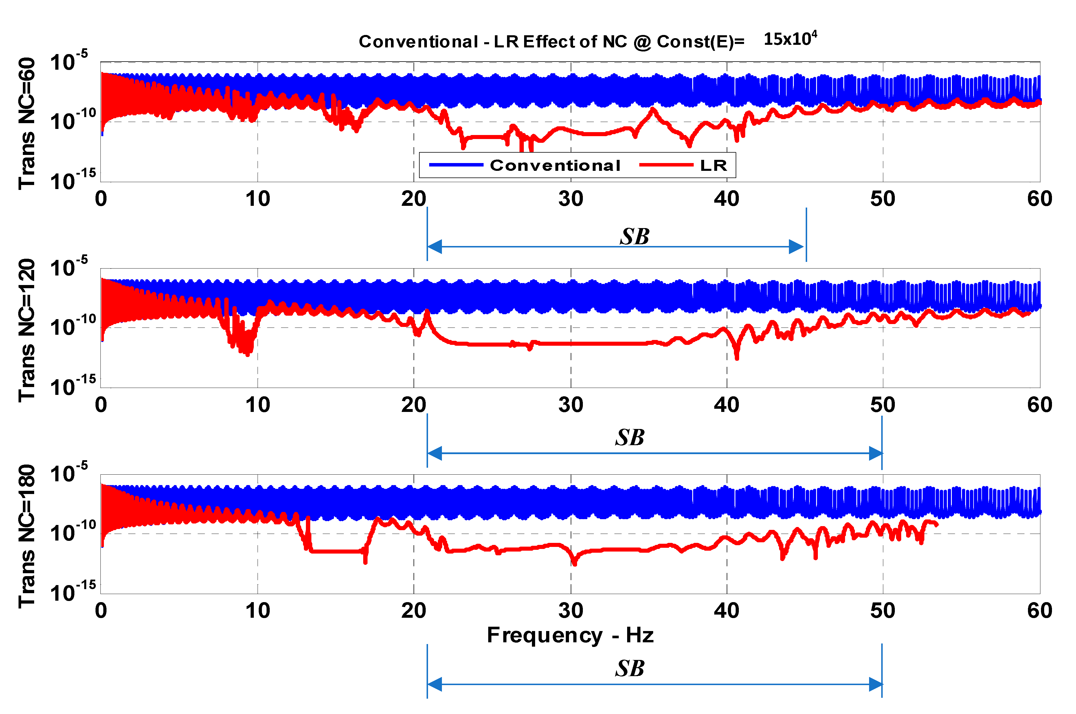
Figure 11, Figure 12 and Figure 13 display comparisons between the frequency response characteristics of a conventional drill-string and a drill-string that has a different number of periodic inserts, with sources of local resonance (LR) for a particular storage modulus of the VEM of the inserts equal to 150 KPa. In Figure 11, the comparisons are established for the torsional vibrations, whereas in Figure 12, the comparisons are presented for the axial vibrations. Figure 13 displays the comparisons for the transverse vibrations.
It can be seen that the periodic inserts with LR resonance become more effective in mitigating the vibration in all directions as the number of inserts is increased. However, a small number of inserts tends to produce stop bands at low frequencies, whereas a large number of inserts results in higher frequency stop bands.
Figure 11, Figure 12 and Figure 13 suggest that increasing the number of the passive periodic inserts with LR results in clearly defining the zones of the stop bands and in increasing the spectral width of these stop bands simultaneously for the rotational, axial, and transverse vibrations.
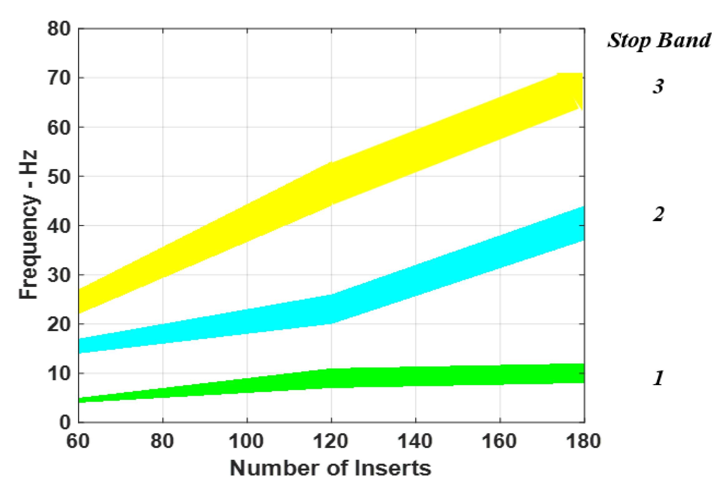
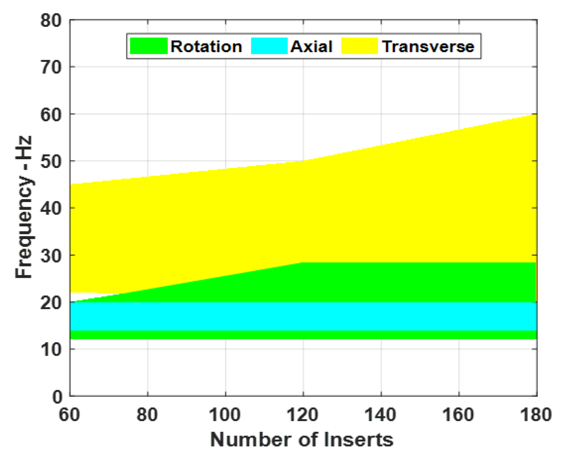
Figure 14 summarizes the effect of the number of periodic inserts with LR on the spectral width of the stop bands for rotational, axial, and transverse vibrations.
It is important to note that the characteristics displayed in Figure 14 indicate that these bands are spectrally fairly wide as compared to those of passive periodic inserts, which are shown in Figure 10. Hence, these bands can be very effective in controlling the drill-string vibration over a wide range of operating conditions such as rotating speed and operating depths. Furthermore, the displayed bands indicate that it is possible to simultaneously control rotational, axial, and transverse vibrations. This is in contrast to the characteristics of passive periodic inserts, which are only limited to the control of bending vibrations. Furthermore, the width of these bands is found to increase significantly with the increased number of inserts.
8. Conclusions
This paper has presented an ANSYS-based finite element model of conventional drill-strings and drill-strings with periodic inserts that have built-in sources of local resonance (LR). The developed models aim at demonstrating the effectiveness of the drill-strings with periodic LR inserts in simultaneously controlling the axial, bending, and torsional modes of vibration of practical drill-strings, particularly at low excitation frequencies. Such effectiveness stems from the ability of the periodic local sources of resonance in shifting the zones of the stop bands to low frequencies, which are compatible with the frequencies experienced by practical drill-strings.
The favorable filtering characteristics of the drill-strings with periodic LR inserts are achieved when the properties of the VEM are tuned to have storage moduli that can generate a considerable attenuation in a manner similar to tuned Den Hartog dampers [33]. The stop bands are obtained at frequencies reaching as low as 5 Hz, which makes the application of the proposed concept practical for many of the existing drill-strings.
It this study, it has been shown that the passive periodic inserts are effective in generating stop bands only in the transverse directions. These stop bands extend to frequencies as low as 5 Hz. However, the inserts are totally ineffective in mitigating the vibration in both the axial and torsional directions. Furthermore, the obtained results indicate that increasing the number of the passive periodic inserts results in clearly defining the zones of the stop bands and in increasing the spectral width of these stop bands. However, the inserts remain effective in mitigating the transverse vibrations only. Moreover, it is observed that increasing the number of inserts has a very limited effect on the width of the stop bands.
When the inserts are provided with sources of LR resonance, it was demonstrated that these configurations become more effective in mitigating the vibration in all directions especially as the number of inserts is increased. However, a small number of inserts tends to produce stop bands at low frequencies, whereas a large number of inserts results in higher frequency stop bands.
Increasing the number of the passive periodic inserts with LR is found to result in clearly defining the zones of the stop bands and in increasing the spectral width of these stop bands simultaneously for the rotational, axial, and transverse vibrations.
It is important to note that the concepts presented in this paper are yet to be implemented in the field of oil-well drilling. The paper, as a conceptual study, aims at investigating the potential and merits of periodic inserts with local resonance in blocking the transmission of vibration along the drill-strings.
Furthermore, the presented concepts are general in nature and are expected to be equally useful in directional wells. As a matter of fact, the concept can be used in any vibration transmission waveguides of any directional orientation.
A natural extension of this paper is to compare the predictions of the ANSYS model with the predictions of a fully developed mathematical model, which starts from the potential and kinetic energies of the entire drill-string, the Rayleigh’s dissipation function, and Lagrangian dynamical equations.
A further extension of this paper includes the process of validating the ANSYS and mathematical FEM models experimentally in order to determine the prediction accuracies and establish the limits of the modeling errors. These FEM models will incorporate the means for prediction of the bandgap and dispersion characteristics based on the approaches outlined in [34,35].
Author Contributions
Conceptualization, A.M.B. and S.S.; methodology, W.A. and H.A.; software, W.A. and H.A.; validation, W.A., A.M.B. and S.S.; formal analysis, W.A. and H.A.; investigation, W.A. and H.A.; data curation, W.A.; writing—original draft preparation, A.M.B. and S.S.; writing—review and editing, A.M.B. and S.S.; visualization, W.A. and H.A.; supervision, A.M.B. and S.S.; project administration, A.M.B. and S.S.; funding acquisition, A.M.B. and S.S. All authors have read and agreed to the published version of the manuscript.
Funding
This research work is funded by Qatar National Research Foundation (QNRF) under grant number NPRP No.: 7-124-2-060.
Institutional Review Board Statement
Not Applicable.
Data Availability Statement
Not Applicable.
Acknowledgments
This research work is funded by the Qatar National Research Foundation (QNRF) under grant number NPRP no. 7-124-2-060. The authors also acknowledge the support of the University of Maryland Supercomputing Resources (http://www.it.umd.edu/hpcc (accessed on 5 September 2017)), which were made available for conducting the research reported in this paper.
Conflicts of Interest
The authors declare no potential conflict of interest with respect to the research, authorship, and/or publication of this article.
References
- Spanos, P.D.; Chevallier, A.M.; Politis, N.P.; Payne, M.L. Oil and gas well drilling: A vibrations perspective. Shock. Vib. Dig. 2003, 35, 85–103. [Google Scholar] [CrossRef]
- Aarrestad, T.V.; Tonnesen, H.A.; Kyllingstad, A. Drill-string vibrations: Comparison between theory and experiments on a full-scale research drilling rig. In Proceedings of the SPE/ADC 14760 Drilling Conference, Dallas, TX, USA, 10–12 February 1986. [Google Scholar]
- Jansen, J.D. Non-linear rotor dynamics as applied to oilwell drill-string vibrations. J. Sound Vib. 1991, 147, 115–135. [Google Scholar] [CrossRef]
- Chen, S.L.; Géradin, M. An improved transfer matrix technique as applied to BHA lateral vibration analysis. J. Sound Vib. 1995, 185, 93–106. [Google Scholar] [CrossRef]
- Yigit, A.S.; Christoforou, A.P. Coupled axial and transverse vibrations of oil well drill-strings. J. Sound Vib. 1996, 195, 617–627. [Google Scholar] [CrossRef]
- Yigit, A.S.; Christoforou, A.P. Coupled torsional and bending vibrations of drill-strings subject to impact with friction. J. Sound Vib. 1998, 215, 167–181. [Google Scholar] [CrossRef]
- Christoforou, A.P.; Yigit, A.S. Dynamic modeling of rotating drill-strings with borehole interactions. J. Sound Vib. 1997, 206, 243–260. [Google Scholar] [CrossRef]
- Khulief, Y.A.; Al-Naser, H. Finite element dynamic analysis of drill-strings. Finite Elem. Anal. Des. 2005, 41, 1270–1288. [Google Scholar] [CrossRef]
- Yigit, A.S.; Christoforou, A.P. Stick-slip and bit-bounce interaction in oil-well drill-strings. J. Energy Resour. Technol. 2006, 128, 268–274. [Google Scholar] [CrossRef]
- Ren, F.S.; Wang, B.J. Modeling and analysis of stick-slip vibration and bit bounce in drill-strings. J. Vibroeng. 2017, 19, 466–488. [Google Scholar] [CrossRef]
- Melakhessou, H.; Berlioz, A.; Ferraris, G. A nonlinear well-drill-string interaction model. ASME J. Vib. Acoust. 2003, 125, 46–52. [Google Scholar] [CrossRef]
- Leine, R.I.; van Campen, D.H.; Keultjes, W.J.G. Stick-slip whirl interaction in drill-string dynamics. J. Vib. Acoust. 2002, 124, 209–220. [Google Scholar] [CrossRef] [Green Version]
- Mihajlovic, N. Torsional and lateral vibrations in flexible rotor systems with friction. Ph.D. Dissertation, Technische Universiteit Eindhoven, Eindhoven, The Netherlands, 2005. [Google Scholar]
- Mihajlovic, N.; van de Wouw, N.; Hendriks, M.P.M.; Nijmeijer, H. Friction-induced limit cycling in flexible rotor systems: An experimental drill-string set-up. J. Nonlinear Dyn. 2006, 46, 273–291. [Google Scholar] [CrossRef] [Green Version]
- Khulief, Y.A.; Al-Sulaiman, F.A.; Bashmal, S. Vibration analysis of drill-strings with self-excited stick-slip oscillations. J. Sound Vib. 2007, 299, 540–558. [Google Scholar] [CrossRef]
- Gulyayev, V.I.; Shevchuk, L.V. Drill string bit whirl simulation with the use of frictional and nonholonomic models. J. Vib. Acoust. 2016, 138, 011021. [Google Scholar] [CrossRef]
- Ahmadabadi, Z.N.; Khadem, S.E. Self-excited oscillations attenuation of drill-string system using nonlinear energy sink. Proc. Inst. Mech. Eng. Part C J. Mech. Eng. Sci. 2013, 227, 230–245. [Google Scholar] [CrossRef]
- Zhu, X.; Lai, C. Design and performance analysis of a magnetorheological fluid damper for drill-string. Int. J. Appl. Electromagn. Mech. 2012, 40, 67–83. [Google Scholar] [CrossRef]
- Moradi, H.; Bakhtiari-Nejad, F.; Sadighi, M. Suppression of the bending vibration of drill strings via an adjustable vibration absorber. Int. J. Acoust. Vib. 2012, 17, 155163. [Google Scholar] [CrossRef]
- Aldushaishi, M.F. Investigation of Drill-String Vibration Reduction Tools. Master’s Thesis, Missouri University of Science and Technology, Rolla, MO, USA, 2012. [Google Scholar]
- Christoforou, A.P.; Yigit, A.S. Fully coupled vibrations of actively controlled drill-strings. J. Sound Vib. 2003, 267, 1029–1045. [Google Scholar] [CrossRef]
- Sarker, M.M.; Rideout, D.G.; Butt, S.D. Advantages of an LQR controller for stick-slip and bit-bounce mitigation in an oilwell drill-string. Paper# IMECE2012-87856. In Proceedings of the ASME 2012 International Mechanical Engineering Congress & Exposition IMECE2012, Houston, TX, USA, 9–15 November 2012. [Google Scholar]
- Karkoub, M.; Zribi, M.; Elchaar, L.; Lamon, L. Robust μ -synthesis controllers for suppressing stick-slip induced vibrations in oil well drill-strings. Multibody Syst. Dyn. 2010, 23, 191–207. [Google Scholar] [CrossRef]
- Li, L.; Zhang, Q.; Rasol, N. Time-varying sliding mode adaptive control for rotary drilling system. J. Comput. 2011, 6, 564–570. [Google Scholar] [CrossRef]
- Alsaffar, Y.; Sassi, S.; Baz, A. Band gap characteristics of non-rotating passive periodic drill string. ASME J. Vib. Acoust. 2017, 140, 021004. [Google Scholar] [CrossRef]
- Alsaffar, Y.; Sassi, S.; Baz, A. Band gap characteristics of periodic gyroscopic systems. J. Sound Vib. 2018, 435, 301–322. [Google Scholar] [CrossRef]
- Baz, A. Active and Passive Vibration Damping; J. Wiley & Sons, Inc.: Hoboken, NJ, USA, 2019. [Google Scholar]
- Baz, A. Active control of periodic structures. ASME J. Vib. Acoust. 2001, 123, 472–479. [Google Scholar] [CrossRef]
- Asiri, S.; Baz, A.; Pines, D. Periodic struts for gearbox support system. J. Vib. Control 2005, 11, 709–721. [Google Scholar] [CrossRef]
- Asiri, S.; Baz, A.; Pines, D. Active periodic struts for a gearbox support system. J. Smart Mater. Struct. 2006, 15, 1707–1714. [Google Scholar] [CrossRef]
- Liu, Z.; Chan, C.T.; Sheng, P. Analytic model of phononic crystals with local resonances. Phys. Rev. B 2005, 71, 014103. [Google Scholar] [CrossRef] [Green Version]
- Hussein, M.I.; Frazier, M.J. Band structure of phononic crystals with general damping. J. Appl. Phys. 2010, 108, 093506. [Google Scholar] [CrossRef]
- Hartog, J.P.D. Mechanical Vibrations; Dover Publications: Mineola, NY, USA, 2013. [Google Scholar]
- Alsaffar, Y.; Aldraihem, O.; Baz, A. Impact and bandgap characteristics of periodic rods with viscoelastic inserts and local resonators. J. Vib. Acoust. 2021, 143, 041011. [Google Scholar] [CrossRef]
- Raafat, M.; Baz, A. Damping and bandgap characteristics of a viscoelastic tensegrity damper. J. Vib. Acoust. 2021, 144, 011001. [Google Scholar] [CrossRef]
Figure 1.
Schematic drawings of conventional (a), periodic (b), and periodic with local resonant inserts (c) drill-strings.
Figure 1.
Schematic drawings of conventional (a), periodic (b), and periodic with local resonant inserts (c) drill-strings.

Figure 2.
Simultaneous control of torsional, axial, and transverse bending vibrations of drill-string with periodic sources of local resonance (VEM: Visco-elastic material).
Figure 2.
Simultaneous control of torsional, axial, and transverse bending vibrations of drill-string with periodic sources of local resonance (VEM: Visco-elastic material).

Figure 3.
Vibration mitigation characteristics of conventional and periodic drill-string. (a) conventional drill string; (b) passive periodic drill string; (c) passive periodic drill string with local resonators.
Figure 3.
Vibration mitigation characteristics of conventional and periodic drill-string. (a) conventional drill string; (b) passive periodic drill string; (c) passive periodic drill string with local resonators.

Figure 4.
Finite element models of shafts with conventional periodic inserts and inserts with built-in sources of local resonance. (a) conventional periodic inserts; (b) inserts with sources of local resonance.
Figure 4.
Finite element models of shafts with conventional periodic inserts and inserts with built-in sources of local resonance. (a) conventional periodic inserts; (b) inserts with sources of local resonance.

Figure 5.
Orbits of the drill-string at the first three modes. (a) f = 0.0325 Hz (0.032 Hz, Khuleif et al. [8,15]); (b) f = 0.0675 Hz (0.0677 Hz, Hhuleif et al. [8,15]); (c) f = 0.111 Hz (0.078 Hz, Khuleif et al. [8,15]).


Figure 6.
Modes of vibration of the inserts with local resonance. (a) first torsional mode: 18.52 Hz; (b) first bending mode: 22.75 Hz; (c) second bending mode: 22.75 Hz; (d) first axial mode: 30.55 Hz; (e) first rubber mode: 180.17 Hz.
Figure 6.
Modes of vibration of the inserts with local resonance. (a) first torsional mode: 18.52 Hz; (b) first bending mode: 22.75 Hz; (c) second bending mode: 22.75 Hz; (d) first axial mode: 30.55 Hz; (e) first rubber mode: 180.17 Hz.


Figure 7.
Comparisons between the frequency response characteristics of a conventional drill-string and a drill-string with 60 passive periodic inserts (SB: Stop band).
Figure 7.
Comparisons between the frequency response characteristics of a conventional drill-string and a drill-string with 60 passive periodic inserts (SB: Stop band).

Figure 8.
Comparisons between the frequency response characteristics of a conventional drill-string and a drill-string with 120 passive periodic inserts (SB: Stop band).
Figure 8.
Comparisons between the frequency response characteristics of a conventional drill-string and a drill-string with 120 passive periodic inserts (SB: Stop band).

Figure 9.
Comparisons between the frequency response characteristics of a conventional drill-string and a drill-string with 180 passive periodic inserts (SB: Stop band).
Figure 9.
Comparisons between the frequency response characteristics of a conventional drill-string and a drill-string with 180 passive periodic inserts (SB: Stop band).

Figure 10.
Effect of number of periodic inserts on the spectral width of the different stop bands of a passive periodic drill-string for the transverse vibration.
Figure 10.
Effect of number of periodic inserts on the spectral width of the different stop bands of a passive periodic drill-string for the transverse vibration.

Figure 11.
Comparisons between the torsional frequency response characteristics of a conventional drill-string and a drill-string, with periodic LR inserts for a different number of inserts when the VEM has a constant storage modulus (SB: Stop band).
Figure 11.
Comparisons between the torsional frequency response characteristics of a conventional drill-string and a drill-string, with periodic LR inserts for a different number of inserts when the VEM has a constant storage modulus (SB: Stop band).

Figure 12.
Comparisons between the axial frequency response characteristics of a conventional drill-string and a drill-string, with periodic LR inserts for a different number of inserts when the VEM has a constant storage modulus (SB: Stop band).
Figure 12.
Comparisons between the axial frequency response characteristics of a conventional drill-string and a drill-string, with periodic LR inserts for a different number of inserts when the VEM has a constant storage modulus (SB: Stop band).

Figure 13.
Comparisons between the transverse frequency response characteristics of a conventional drill-string and a drill-string, with periodic LR inserts for a different number of inserts when the VEM has a constant storage modulus (SB: Stop band).
Figure 13.
Comparisons between the transverse frequency response characteristics of a conventional drill-string and a drill-string, with periodic LR inserts for a different number of inserts when the VEM has a constant storage modulus (SB: Stop band).

Figure 14.
Effect of number of periodic inserts with LR on the spectral width of the stop bands of a passive periodic drill-string for the rotation, axial, and transverse vibrations.
Figure 14.
Effect of number of periodic inserts with LR on the spectral width of the stop bands of a passive periodic drill-string for the rotation, axial, and transverse vibrations.


Table 1.
Main physical and geometrical parameters of the drill-string under consideration (Khulief et al. [8,15]).
| Specifications | Value |
|---|---|
| Drill Pipe | |
| Length (Lp) | 1000 m |
| Outer Diameter (Do) | 0.127 m |
| Inner Diameter (Di) | 0.095 m |
| Density (ρ) | 7850 kg/m3 |
| Modulus of Elasticity (E) | 210 GPa |
| Shear Modulus (G) | 77.9 GPa |
| Collar | |
| Outer Diameter (Dc) | 0.2286 m |
Table 2.
Main physical and geometrical parameters of the considered periodic inserts.
| Specifications | Value |
|---|---|
| Periodic Inserts | |
| Width (W) | 0.25 m |
| Outer Diameteri (Doi) | 0.2286 m |
| Inner Diameteri (Dii) | 0.127 m |
| Density (ρ) | 7800 kg/m3 |
| Modulus of Elasticity (E) | 210 GPa |
| Poisson’s ratio (ν) | 0.365 |
| Loss factor (η) | 2 × 10⁻⁵ |
Table 3.
Main geometrical parameters of the considered periodic inserts with sources of local resonance (three layers: Inner steel ring, VEM, outer steel ring).
Table 3.
Main geometrical parameters of the considered periodic inserts with sources of local resonance (three layers: Inner steel ring, VEM, outer steel ring).
| Specifications | Value |
|---|---|
| Inner Layer | |
| Width (W) | 0.2500 m |
| Outer Diameteri (Doi) | 0.1524 m |
| Inner Diameteri (Dii) | 0.1270 m |
| Intermediate Layer | |
| Outer Diameteri (Doi) | 0.1905 m |
| Inner Diameteri (Dii) | 0.1524 m |
| Outer Layer | |
| Outer Diameteri (Doi) | 0.2286 m |
| Inner Diameteri (Dii) | 0.1905 m |
Table 4.
Main parameters of the VEM Intermediate layer of the periodic inserts.
| Specifications | Value |
|---|---|
| Constant Storage Modulus (E′) | 15, 50, 100, 150 kN/m2 |
| Loss Factor (η) | 0.10 |
| Poisson’s ratio (ν) | 0.49 |
| Density (ρ) | 1100 kg/m3 |
Publisher’s Note: MDPI stays neutral with regard to jurisdictional claims in published maps and institutional affiliations. |
© 2021 by the authors. Licensee MDPI, Basel, Switzerland. This article is an open access article distributed under the terms and conditions of the Creative Commons Attribution (CC BY) license (https://creativecommons.org/licenses/by/4.0/).
Share and Cite
MDPI and ACS Style
Akl, W.; Alsupie, H.; Sassi, S.; Baz, A.M. Vibration of Periodic Drill-Strings with Local Sources of Resonance. Vibration 2021, 4, 586-601. https://0-doi-org.brum.beds.ac.uk/10.3390/vibration4030034
AMA Style
Akl W, Alsupie H, Sassi S, Baz AM. Vibration of Periodic Drill-Strings with Local Sources of Resonance. Vibration. 2021; 4(3):586-601. https://0-doi-org.brum.beds.ac.uk/10.3390/vibration4030034
Chicago/Turabian StyleAkl, Wael, Hajid Alsupie, Sadok Sassi, and Amr M. Baz. 2021. "Vibration of Periodic Drill-Strings with Local Sources of Resonance" Vibration 4, no. 3: 586-601. https://0-doi-org.brum.beds.ac.uk/10.3390/vibration4030034