Stabilization of Vehicle Dynamics by Tire Digital Control—Tire Disturbance Control Algorithm for an Electric Motor Drive System


Abstract
:1. Introduction
2. Algorithm
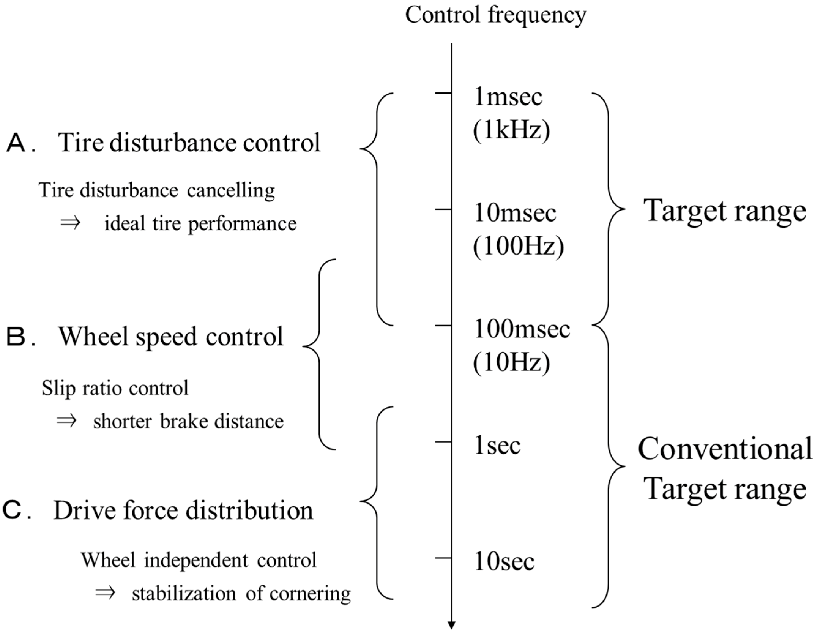
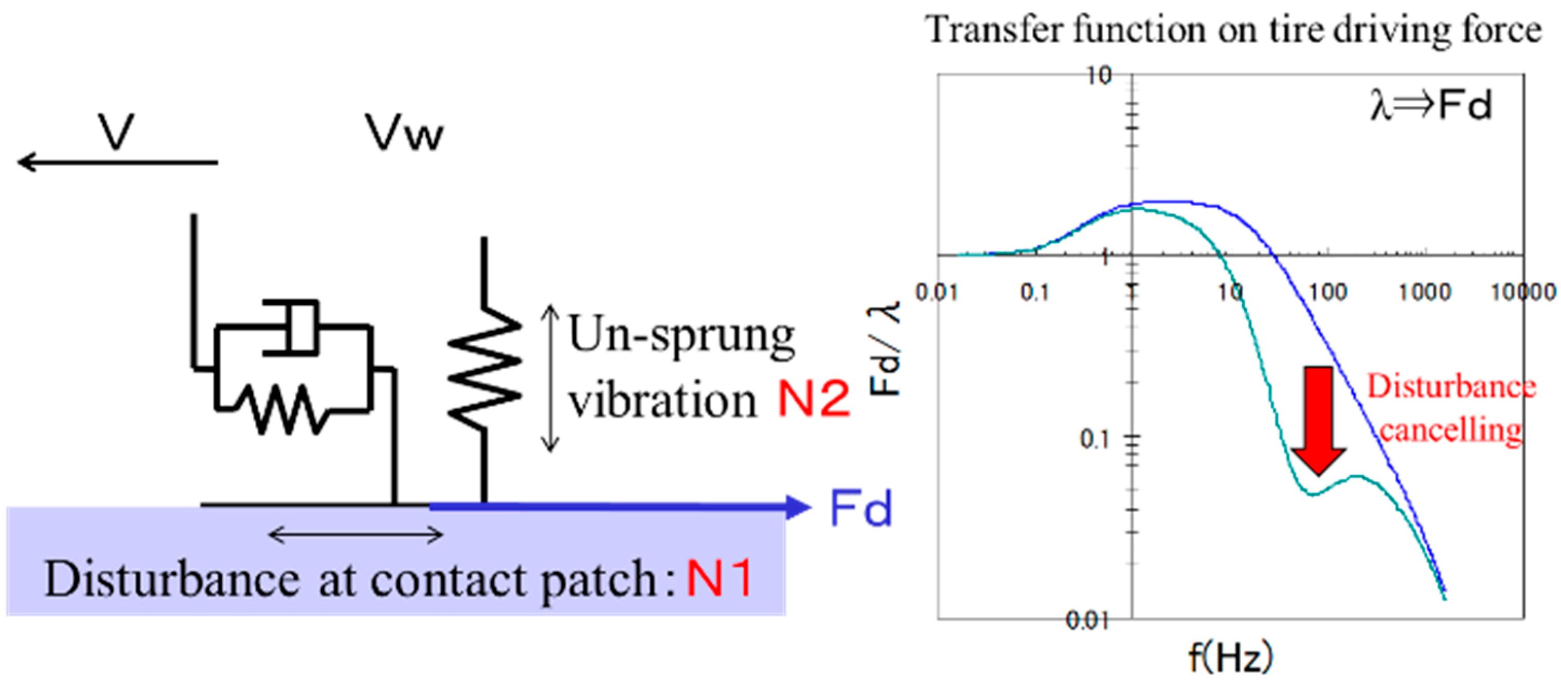
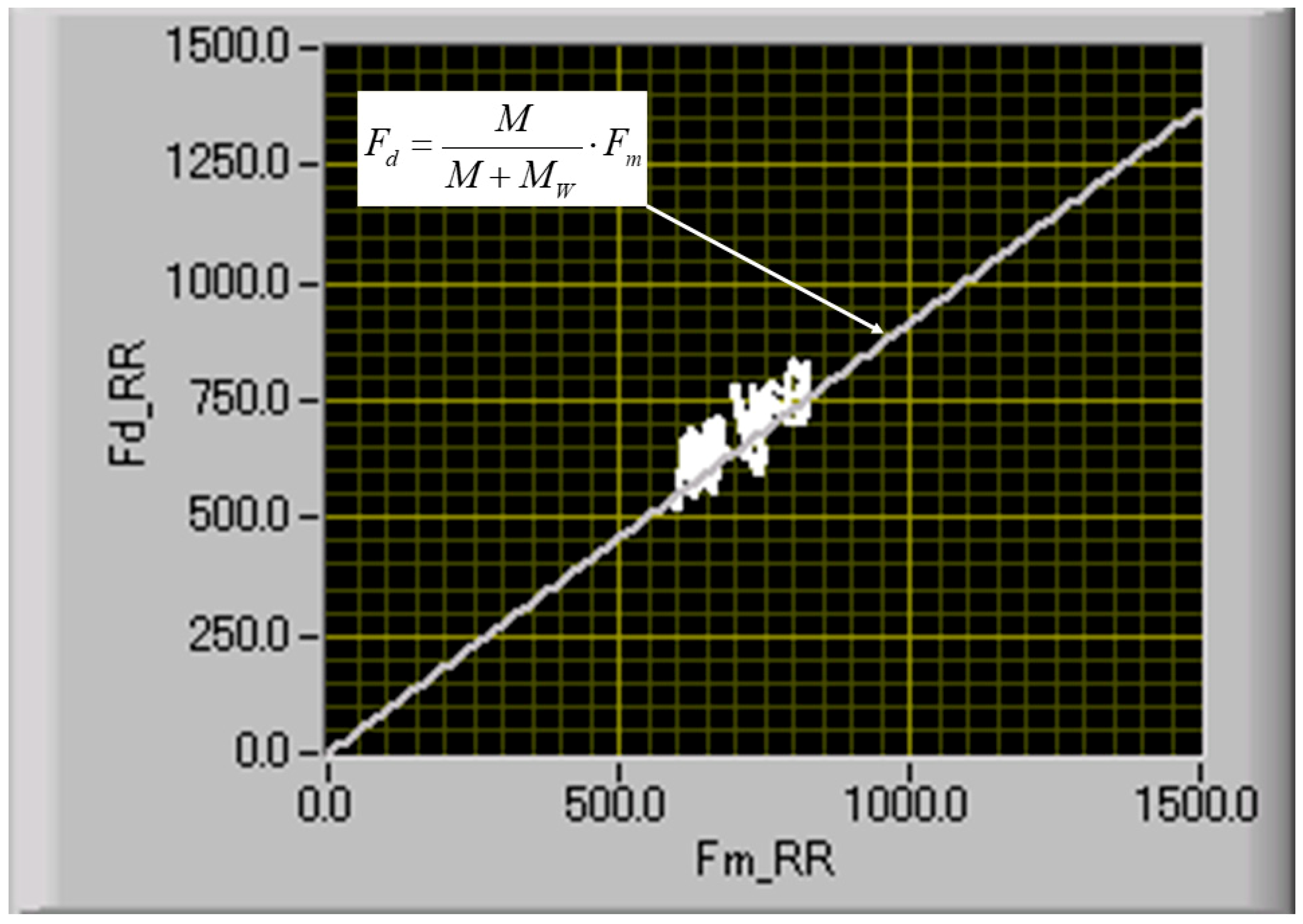
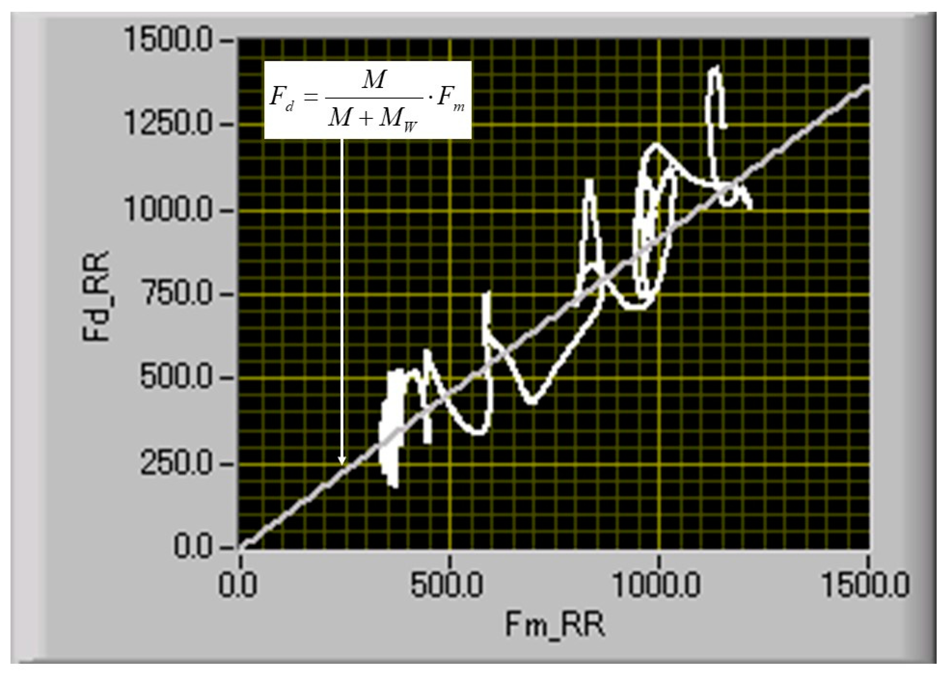
2.1. Tire Disturbance Control
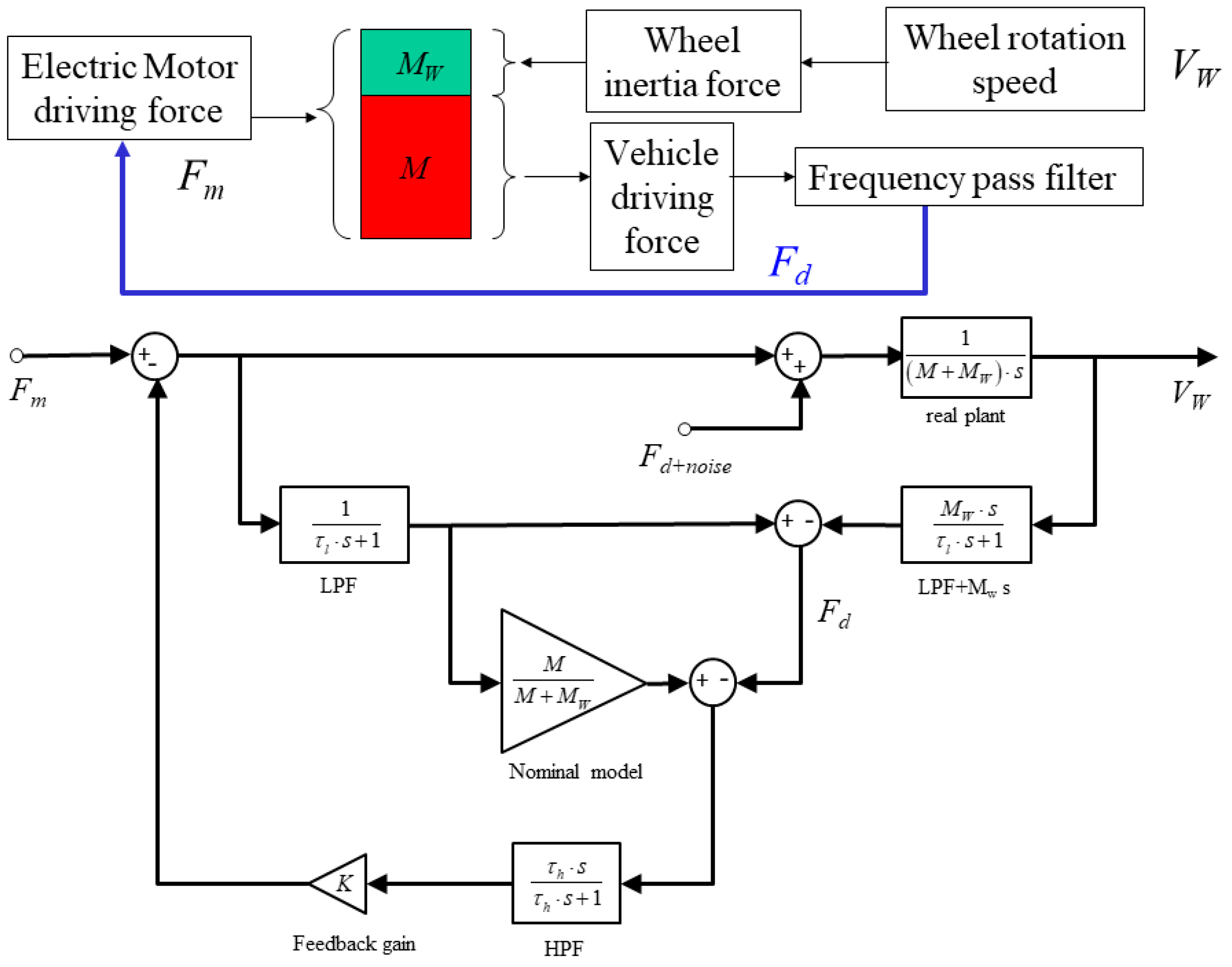
2.2. Tire Disturbance Control Algorithm
3. Results
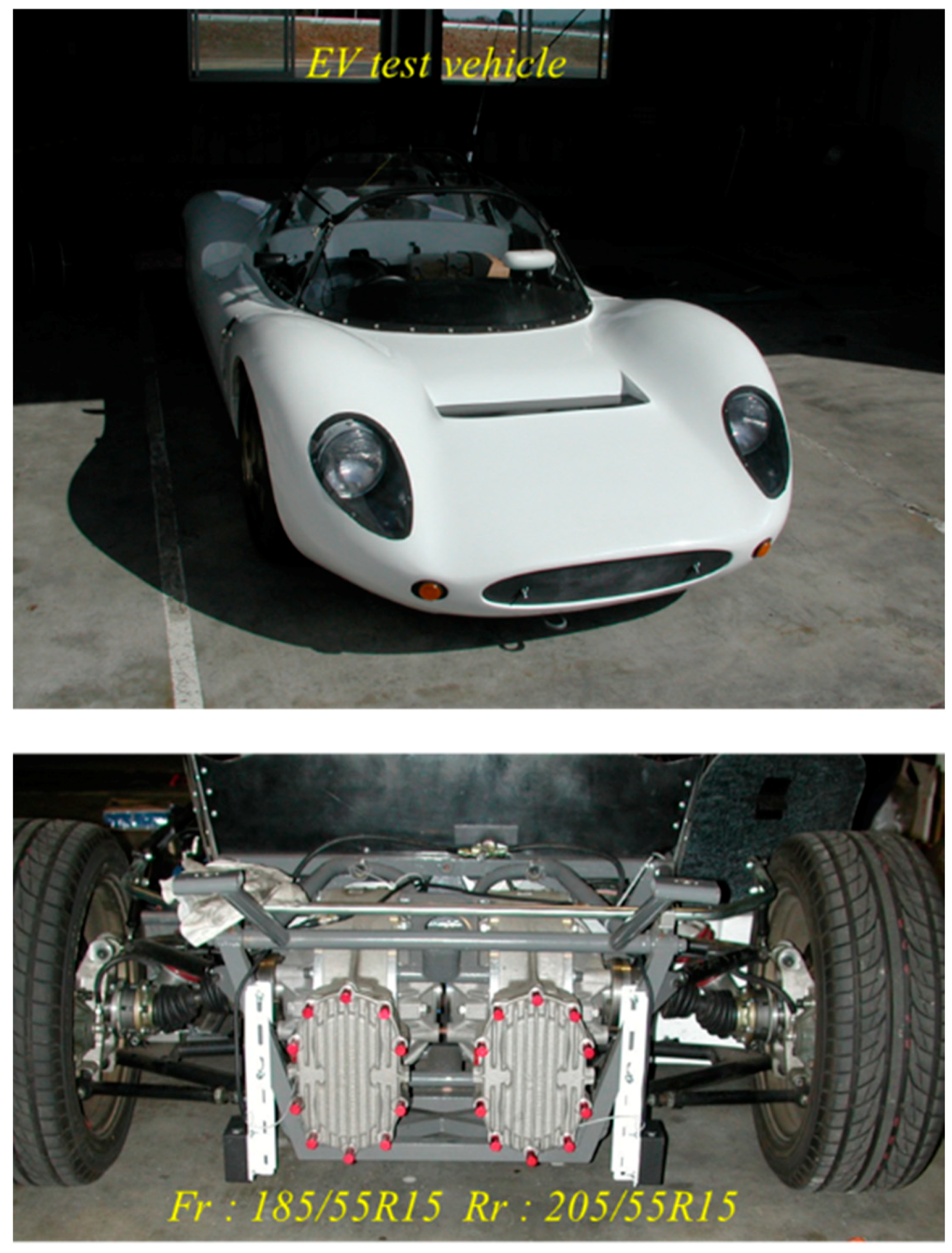
3.1. Test Vehicle
3.2. Test Method
4. Results and Discussion
4.1. Effect of Applied Control Frequency
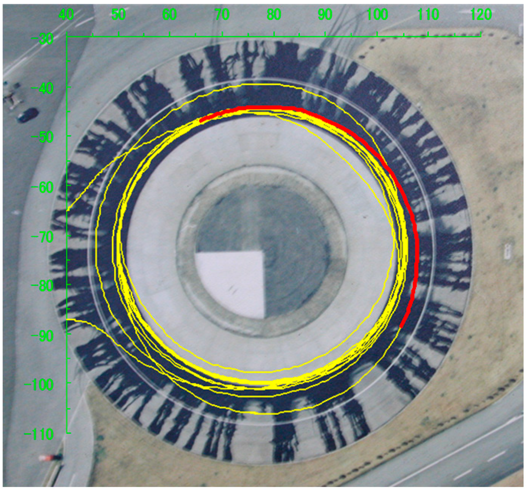
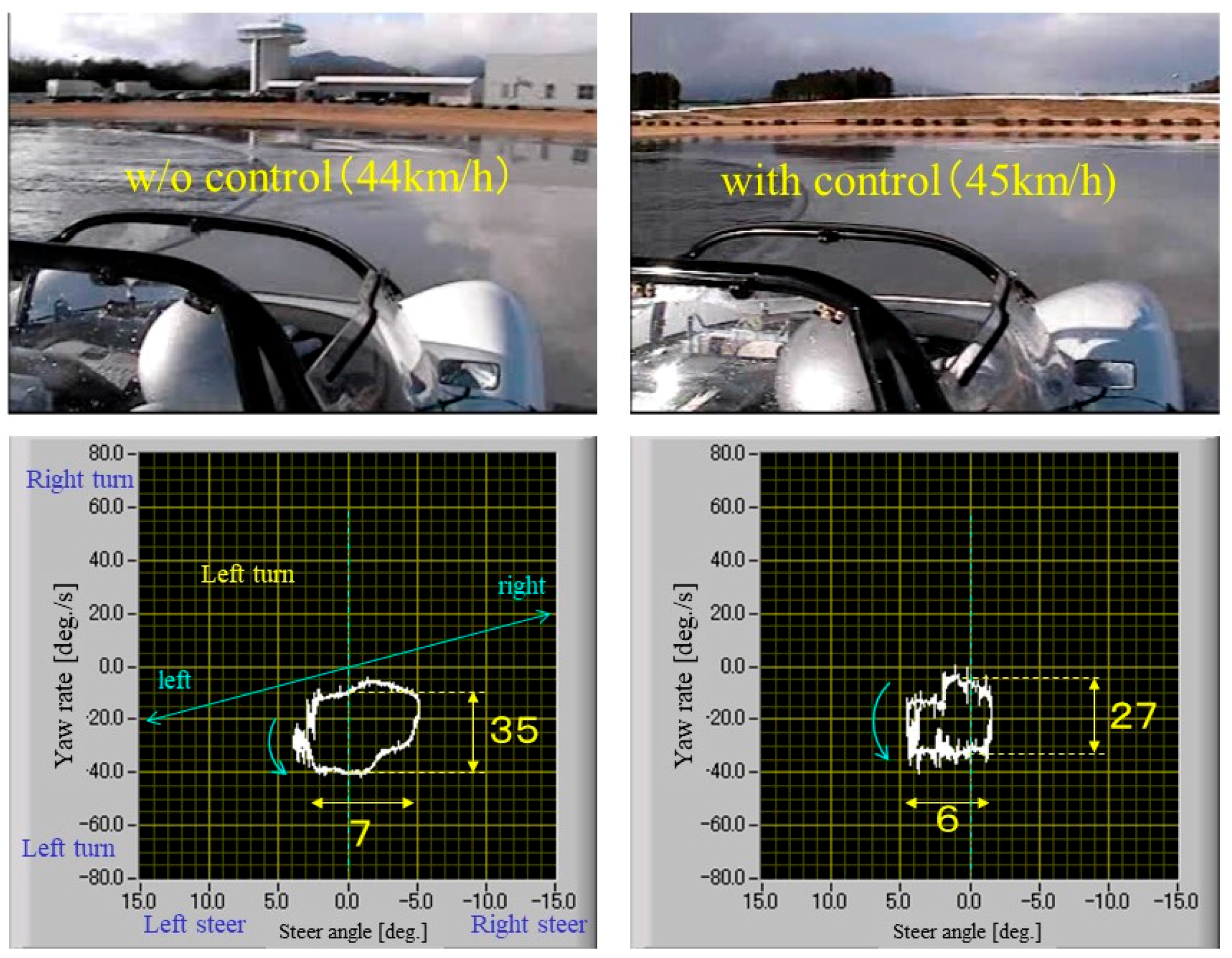
4.2. Stabilization of Steering on the Wet Skid Pad
5. Conclusions
Supplementary Materials
Author Contributions
Funding
Acknowledgments
Conflicts of Interest
References
- Global Electric Vehicle (EV) Outlook 2018. Available online: https://www.iea.org/gevo2018/ (accessed on 15 April 2019).
- Anderson, Z.M.; Glovanardi, M.; Tucker, C.; Ekehian, J.A. Active Safety Suspension System. US2017/0137023, 18 May 2017. [Google Scholar]
- Wang, Y.; Fujimoto, H.; Hara, S. Driving Force Distribution and Control for EV with Four In-Wheel Motors: A Case Study of Acceleration on Split-Friction Surfaces. IEEE Trans. Ind. Electron. 2016, 64, 3380–3388. [Google Scholar] [CrossRef]
- Nam, K.; Oh, S.; Fujimoto, H.; Hori, Y. Estimation of Sideslip and Roll Angles of Electric Vehicles Using Lateral Tire Force Sensors Through RLS and Kalman Filter Approaches. IEEE Trans. Ind. Electron. 2012, 60, 988–1000. [Google Scholar] [CrossRef]
- Hu, J.; Wang, Y.; Fujimoto, H.; Hori, Y. Robust Yaw Stability Control for In-wheel Motor Electric Vehicles. IEEE/ASME Trans. Mechatron. 2017, 22, 1360–1370. [Google Scholar] [CrossRef]
- Sato, M.; Yamamoto, G.; Gunji, D.; Imura, T.; Fujimoto, H. Development of Wireless In-Wheel Motor Using Magnetic Resonance Coupling. IEEE Trans. Power Electron. 2016, 31, 5270–5278. [Google Scholar] [CrossRef]
- Nagaya, G.; Wakao, Y.; Abe, A. Development of an in-wheel drive with advanced dynamic-damper mechanism. JSAE Rev. 2003, 24, 477–481. [Google Scholar] [CrossRef]
- Hori, Y.; Toyoda, Y.; Tsuruoka, Y. Traction Control of Electric Vehicle: Basic Experimental Results using the Test EV UOT Electric March. IEEE Trans. Ind. Appl. 1998, 34, 1131–1138. [Google Scholar] [CrossRef]
- Clark, S.K. Mechanics of Pneumatic Tires; Chapter 9, Analysis of tire properties; National Highway Traffic Safety Administration: Washington, DC, USA, 1981; pp. 721–757.
- Wakao, Y.; Akutagawa, K. Method And Device For Controlling Vehicle. EP1502805A1, 2 February 2005. [Google Scholar]
- Hori, Y.; Sakai, S.; Sado, H.; Uchida, T. Motion Control of Electric Vehicle Utilizing Fast Torque Response of Electric Motor. IFAC Proc. Vol. 1999, 32, 8166–8171. [Google Scholar] [CrossRef]
- Nasukawa, K.; Miyashita, Y.; Shiokawa, M. Jidousha No Soukouseinou To Shikenhou. In Efficiency Tests for Running, 3rd ed.; Sankaido: Tokyo, Japan, 1993; p. 217. [Google Scholar]


© 2019 by the authors. Licensee MDPI, Basel, Switzerland. This article is an open access article distributed under the terms and conditions of the Creative Commons Attribution (CC BY) license (http://creativecommons.org/licenses/by/4.0/).
Share and Cite
Akutagawa, K.; Wakao, Y. Stabilization of Vehicle Dynamics by Tire Digital Control—Tire Disturbance Control Algorithm for an Electric Motor Drive System. World Electr. Veh. J. 2019, 10, 25. https://0-doi-org.brum.beds.ac.uk/10.3390/wevj10020025
Akutagawa K, Wakao Y. Stabilization of Vehicle Dynamics by Tire Digital Control—Tire Disturbance Control Algorithm for an Electric Motor Drive System. World Electric Vehicle Journal. 2019; 10(2):25. https://0-doi-org.brum.beds.ac.uk/10.3390/wevj10020025
Chicago/Turabian StyleAkutagawa, Keizo, and Yasumichi Wakao. 2019. "Stabilization of Vehicle Dynamics by Tire Digital Control—Tire Disturbance Control Algorithm for an Electric Motor Drive System" World Electric Vehicle Journal 10, no. 2: 25. https://0-doi-org.brum.beds.ac.uk/10.3390/wevj10020025