1. Introduction
Lithium-ion batteries are widely seen as a promising solution for both power generation, as in electric vehicles, and energy storage, to cope with the variable and intermittent renewable energy. Despite providing great performance through high energy density and long service lives, lithium-ion batteries require accurate monitoring to ensure the user’s safety. Indeed, high temperatures, overcharging and over-discharging damage the cell and endanger the user. Therefore, every battery pack includes a battery management system (BMS) to stop charging and discharging the battery as soon as one cell exits its safe operating bounds [
1].
This represents a critical limitation, as unbalancing the state of health (SoH) can cause some weak cells to reach the limits of charging and discharging much sooner than others [
2]. The difference between cells in the same battery pack in the total number of complete cycles reached before the end of life can be up to 350 cycles between the best and worst cell [
3]. For technical, economic and environmental considerations, balancing strategies [
4] were developed to equalize the state of charge of cells.
Typical balancing used in most of manufactured Li-ion battery systems consists of dissipating some energy of the fully charged cells to achieve the charge of the other cells. This solution compensates only a difference in coulombic efficiency between cells and not a difference in capacity. It is always the weakest cell that limits the capacity of the full battery pack and which ends up being the most exploited. Then the weakest cell ages the most, which increases capacity differences over the time.
In order to use the full capacity of all cells of a battery pack, more advanced balancing strategies are applied, such as active balancing, which uses power electronic components to exchange energy from the strongest cells to the weakest ones [
5]. Other strategies use self-reconfigurable battery (SRB) architectures to manage the average current drawn on each cell to provide the output power [
6]. Some studies address the efficiency improvement of adjusting the output voltage by such battery reconfiguration compare to the use of an external DC/DC converter [
7]. Others have proposed to generate a staircase-shaped sinusoidal waveform in order to replace the AC/DC battery charger [
8] and the DC/AC motor inverter [
9]. This is an attractive prospect, as it is well known that a great amount of energy is lost in AC–DC inverters [
10].
Staircase-shaped waveforms are usually generated from multilevel converters using carrier phase shift pulse width modulation (PWM) or carrier cascaded PWM [
11]. The modular multilevel converter (MMC) with a battery energy storage system (MMC–BESS) has been proposed as a new three-phases topology using SRB for the traction drive [
12] and for stationary batteries for fast charging EV charging stations [
13,
14]. In those studies, MMC–BESS are used in single star topology with cascaded H-bridges, or in dual-star topology with only half-bridge chopper switches and twice the required number of cells. Both incorporate one to several cells in series per adjustable series level in the MMC. Due to the high number of levels, the generated three-phase AC signal offers a low total harmonic distortion (THD) in the output voltage and current. This considerably reduces the need for output power filtering and shows direct benefits in the motor efficiency [
15]. Among the SRBs capable of generating sinusoidal waveforms, few offer direct on-grid recharging and all use cascaded carrier PWM control schemes. These, when embedded, are implemented on digital signal processor (DSP) and field-programmable gate array (FPGA) targets, and refreshed at only few KHz. Moreover, sudden fluctuations in network voltage require immediate adjustment of the output voltage, which can be difficult to achieve with such control schemes. In addition, the occurrence of cell faults requires the ability to overcome failures to avoid unexpected carrier offset under various modulation indices [
16].
This paper demonstrates the feasibility of embedding cell-switching strategies in a microcontroller with the use of field buses, low voltage MOSFET and a single current sensor. The aim is to obtain a cost-efficient SRB able—on the one hand—to charge itself directly on the power grid while reducing the requirement of passive filtering components, and on the other hand to generate a perfect output waveform signal. All this while allowing the exclusion of defective cells and performing real-time cell balancing.
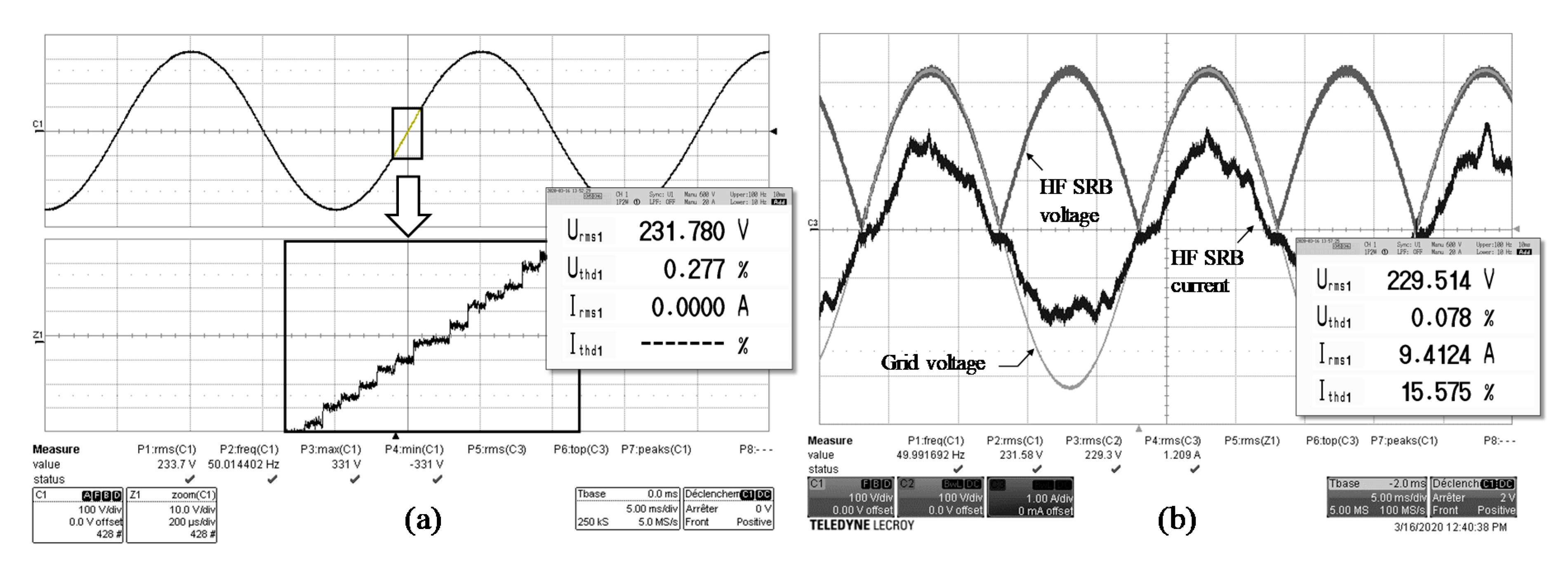
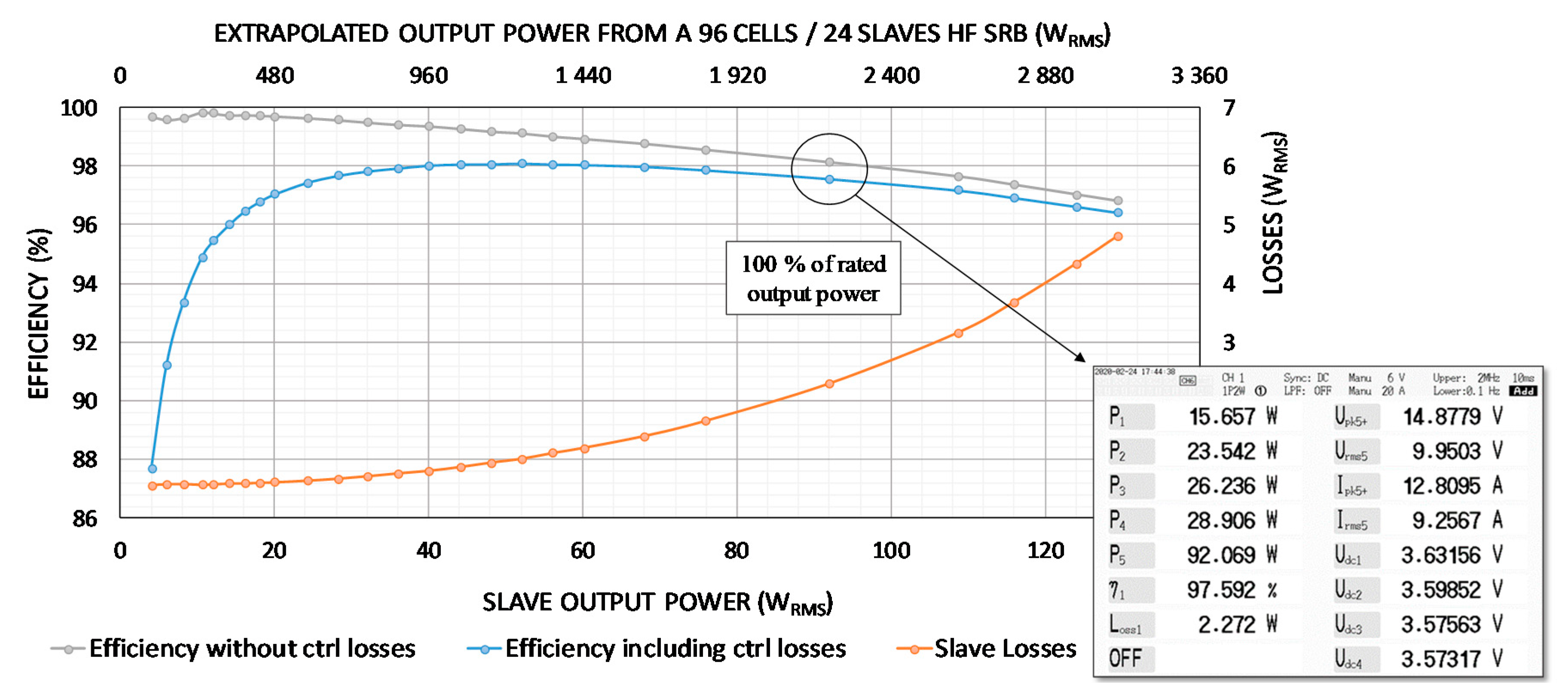
This document is composed as follows: The first section introduces SRB fundamentals and those more specific of the proposed system. The second section describes the hardware architecture implemented. Then, the third section describes the software’s advanced functions. The following section presents the experimental results, such as SoC balancing, THD and efficiency of the high frequency SRB (HF SRB), through the implementation of a real battery with 128 cells. Finally, the last section concludes on the performances demonstrated by the results obtained and develops the perspectives that follow.
2. SRB Fundamentals
The key idea of the SRB is to introduce individual control of each cell in the battery pack by means of dedicated switches placed in series and parallel with each cell [
17]. With such management, it becomes possible to disconnect only the weakest or damaged cells and provide the required power with the remaining ones. Moreover, bypassing switches offer the capability to adjust the number
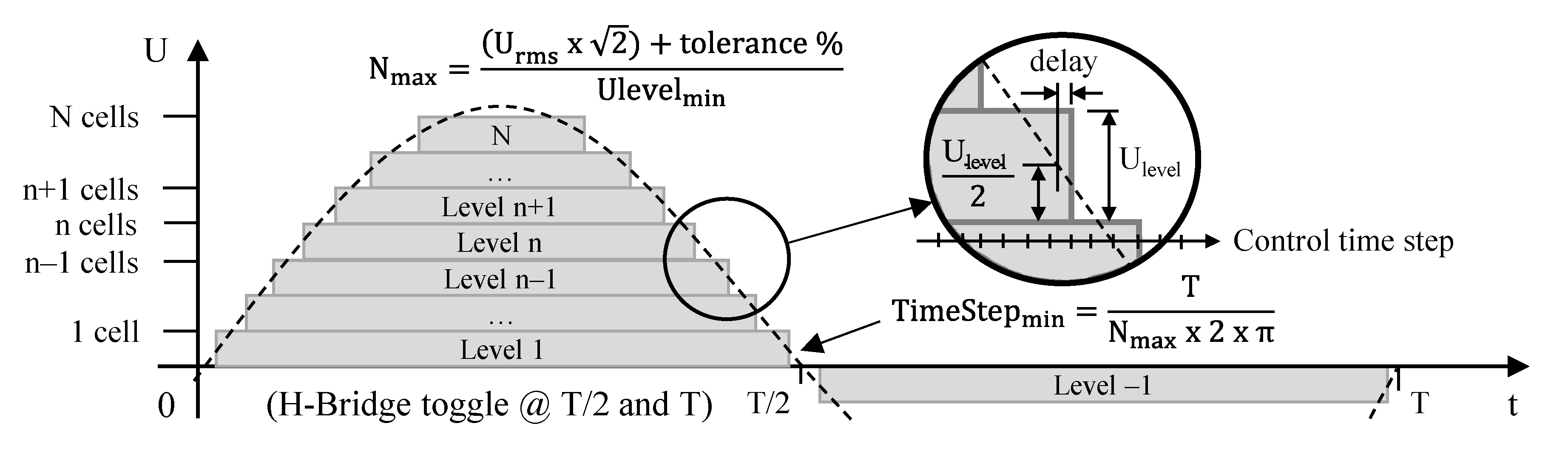
N of cells placed in series and thus to adjust the output voltage of the battery. The generation of an AC waveform voltage from a SRB relies on the sequential superimposition of each cell voltage resulting in a staircase-shaped signal, as shown in
Figure 1. A cell insertion increases the output voltage of one cell voltage; we name that voltage increment a “level,” level 1 being the first step, and level n the nth step. A level is not attached to a particular cell; any cell of the battery pack can ensure that level. As shown in
Figure 1, each level performs four switching operations within a sinusoidal period. Therefore, in order to generate a 50 Hz sinusoidal waveform, the switching frequency of a level is 200 Hz. However, in order to generate an accurate waveform in its steepest part, it is necessary to respect a minimum time step (TimeStep
min) between two level changes. In the case of a sinusoidal waveform of period (T) and maximum peak value of the number of levels connected in series (N
max), the steepest part is reached at the zero crossing where TimeStep
min can be estimated from the derivative of the signal, as given by the formula shown in
Figure 1.
When taking EU electrical network voltage as an example, which is 230 VRMS +/− 10% with a frequency of 50 Hz, and using cells which the specified end of discharge threshold is 2800 mV, Nmax reaches 128 and the related minimum time step is then about 25 µs, which corresponds to an equivalent switching frequency of 40 kHz. This frequency can be reduced if more than one level can be switched at each control time step. Note that the battery pack could include additional cells that could be used to provide the maximum voltage output in case of cell failures; therefore, the number of cells could be greater than Nmax without affecting TimeStepmin.
Recharging a SRB directly on the electrical network consists of tracking the electrical network voltage and applying a slightly smaller voltage at the SRB output. The small voltage difference (δV
) is applied to the internal impedance of the SRB (Z
SRB). This induces a current exchange approximately proportional to that voltage difference which can reaches 0.5 A/V for a SRB of 128 levels of single 18,650 NMC cells, such as Sony VTC6. Therefore, generating a waveform for charging purpose implies a tight synchronization with the electrical network voltage waveform to avoid any excessive current exchange due to control time delay, as detailed in
Section 4.2. The periodic aspect of the electrical network voltage facilitates this control. However, it can present stochastic deformations, which is why a power filtering stage is usually required in existing SRBs to filter out these unpredictable disturbances.
The control strategy implemented in the proposed system is then quite different than carrier cascaded PWM in order to be embedded on microcontrollers. Here, a nearest level control (NLC) is performed. The number of levels in series to activate is then determined in real-time by rounding up to the nearest integer the real value given by a closed-loop control. The use of NLC for SRB driving has been compared with carrier cascaded PWM in [
18]. It was shown that PWM control patterns tend to have a better THD when a low number of levels in series is used, while NLC induces less loss due to the reduced amount of commutations. This study was done on a SRB with 9 levels of unit blocks having 5 cells in series; therefore, the NLC THD results should be better with a higher number of levels.
Waveforms generated with our system are similar to those from carrier cascaded PWM, but the management of electrical grid disturbances and cells faults is now possible within a half cycle of the sinusoidal voltage without signal perturbation. A control loop updates the reference waveform in real time, which allows forthwith management of the electrical network voltage perturbations. The first in first out (FIFO) principle is applied to connect and disconnect the cells. The selection of the cell to be connected or disconnected is performed on the fly in a priority order provided by a balancing algorithm. The failing cells are handled forthwith without disturbing the generated waveform by means of a cell swap operation. The priority order of the cell use is given by a ranking X(t), which is updated over the time from the availability of the cells and by the balancing algorithm. As illustrated in
Figure 2, the first four levels are connected from time t
1 to t
4 according to the reference signal. At time t
5, a fault occurs on cell B, which is associated with the third level. This faulty cell is disconnected and instantly removed from the list of available cells list in the ranking X(t). This ranking gives cell G as the next available cell to be connected in replacement of the faulty cell. At time t
6, the cell ranking X(t) is updated by the balancing algorithm. Cell G, now with rank five, is immediately replaced by cell J that has now rank four. Then cell J is disconnected at t
7 when only three levels are required in order to follow the theoretical waveform. At time t
8, only two levels are required and cell
C is disconnected as requested by the ranking X(t). At time t
9, only one level is required and the cell D is disconnected. At time t
10, the zero-crossing point of the voltage is reached. The cell A is disconnected and then all cells are bypassed. The negative part of the waveform is generated using the inverter H-bridges distributed on each module containing 4 cells (see
Figure 3), while cells are connected successively in the order given by the cell ranking X(t) (cell A first). The following sections show how the CEA has implemented the innovations presented above.
3. Hardware Architecture
3.1. Master/Slave Organization
Distributed systems have been commonly used in classical BMS implementations to address large cable bundles issues. They are based on a central unit and multiple remote units where remote units are arranged against groups of cells. The SRB requires the use of switches whose number and control complexity increase with the number of cells used and the number of degrees of freedom it integrates (series, parallel, series and parallel, etc.). Some works address the complexity of a centralized control of all switches by using neural networks and reinforcing learning to optimize the control strategy [
19]. Others propose the use of different levels of abstraction distributed on different processing units to reduce this complexity [
20]. Others even propose to distribute the control decision at different levels [
21,
22].
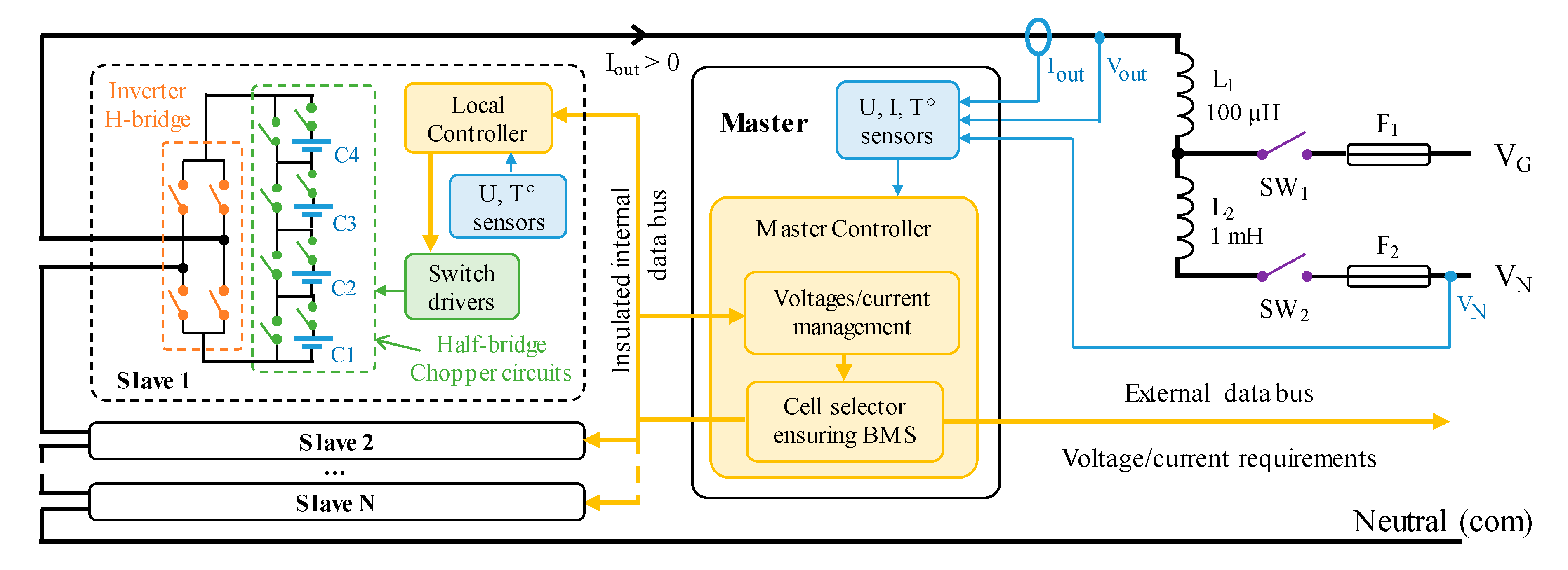
We propose to exploit the concept of distributing switches and their physical drivers over the battery pack while maintaining centralized control of the overall cell layout and monitoring. For this purpose, the SRB is divided into remote modules named “slaves” and a central module named “master.” As argued in
Section 3.4, each slave is composed of four cells connected in series through half-bridge chopper circuits, an H-bridge to reverse the polarity of the module and a local controller. Then slaves are chained to reach the required output voltage. An overview of the overall hardware architecture is given in
Figure 3. V
out is the output-to-com voltage of the HF SRB, V
N is the line-to-neutral voltage into which the AC charger voltage comes in and V
G is the generated AC voltage for the battery discharging.
The master module is in charge of managing all slave modules thanks to a master controller. It estimates the state of each cell and manages the safety according to data collected through the remote modules (mainly cells’ voltages and temperatures). The selection of the cells to be inserted in the power path is performed in the master controller, while slaves switch actuation and cell parameter measurement. However, H. Kim et al. [
21] suggests performing the cell selection in a distributed way; otherwise the control latency will increase significantly with the number of levels in series used in a SRB. In
Section 4.1 we will show how to deal with this issue and what the impact is of increasing the number of levels over the driving latency with the proposed solution. The centralized management of the SRB allows one to use very low-cost local controllers. The use of a shared communication bus is required in order to reduce the number of wires in the system. These must be carefully designed to withstand disturbances related to switching, as shown in
Section 3.2.
3.2. Communication Buses
The splitting of the SRB into a distributed system requires the use of a reliable communication bus for safety reasons. The generation of arbitrary waveforms implies real-time constraints on the transmitted commands. The controller area network (CAN bus) is reliable but not suitable for transmitting commands at high frequency. The reliability of a faster real-time communication bus like a universal asynchronous receiver transmitter (UART) can be enhanced by the use of differential transmission lines and additional software mechanisms, such as cyclic redundancy checking (CRC).
Switch command messages are less critical than cell voltage and cell temperature data. Indeed, the safety of the switch control is ensured at the level of the local controller, while the real time control loop performed at the master level can compensate for an incorrect number of activated levels in series as soon as the next control period occurs. We propose to separate real-time data from critical data by using a combination of CAN and RS485 busses. In this way, real-time data can be transmitted at higher frequency while critical data can be safely transmitted at low frequency with a lower bandwidth.
3.3. SRB Control Strategy
Iteratively changing the number of active levels in series allows the master controller to communicate individually and asynchronously with each local controller in order to locally modify the configuration of the cells. Thus, each local controller is only called when one of its cells is concerned by the refresh of the series arrangement. The control frequency is limited by the master controller since the local controllers are called asynchronously at low frequency. While this sequential control has the potential to allow high command frequencies, only a few levels in series can be controlled at a time, as the length of the control message is limited by the length of the control period. A higher control frequency could be achieved by distributing the control of the slaves over several buses.
An alternative could be to transmit the required number of active levels in series to all the local controllers in a single message sent over the real-time communication bus. The rank of each local controller could be transmitted in the background at low frequency on the CAN communication bus. This way, the full voltage amplitude of the SRB can be reached forthwith in one step. Another option is that all local controllers are called up at each control command, even if this is unnecessary. The local controllers have to be as inexpensive and as low power as possible due to the large number used in the SRB. Therefore, the use of low power microcontrollers limits the call up frequency rate.
For direct charging of the SRB on the electrical grid, a moderate rise time is acceptable if the control frequency is sufficient. The rest of this study is therefore based on asynchronous iterative control of the local controllers performed at 20 kHz with a maximum of three slave calls per control period, hence between 1 and 12 levels for each control periods. This reduces the computing power required by the local controller sufficiently to allow the use of microcontrollers operating at frequencies as low as 48 MHz, such as the STM32F091.
3.4. Slave Switches’ Choices and Thermal Considerations
Switching losses are theoretically very low due to the low voltage and low switching frequency of each switch. With regard to conduction losses, the internal impedance of switches is generally proportional to their nominal voltage. The sum of the impedances of the switches in series should correspond to that of a conventional inverter. Thus, the conduction losses should be equivalent. Moreover, unlike conventional inverters, the heat distribution over the entire battery pack does not require a specific cooling system. In addition, the choice of the number of switches used in parallel makes it possible to adjust the conduction losses relative to the losses induced by the internal impedance of the cells through which the same current flows. However, there is no point in reducing the conduction losses of the switches too much, as the impedance of the cells generates large joule losses.
Thus, an impedance ratio of 1/10 has been targeted in order to make the conduction losses of the switches negligible compared to those presented by the cells themselves. From a thermal point of view, this means that the additional heating near the cells will be of the order of 10%. In other words, 90% of the heating observed in the HF SRB will be due to the self-heating of the cells. In addition to the inverter’s cooling-specific system savings, the prospect of carrying out cell temperature balancing offers the possibility of relieving the constraints applied on the thermal management system of the battery pack.
3.5. Master
As for the case of central units of classical BMS, the master controller centralizes all cell voltage and temperature measurements transmitted by the local controllers. It is interfaced with the outside of the HF SRB, which provides operating mode instructions (charge/discharge mode, 48 VDC, 230 VAC, etc.) and to which it transmits status information such as state of charge (SoC), state of power (SoP), state of energy (SoE) and state of health (SoH) battery states through its estimators. It is also the place where all the tasks that cannot be distributed to the local controllers are carried out, such as measuring the battery pack current, managing the main power relays or monitoring their upstream and downstream voltages.
More specifically to the HF SRB management, the master controller is in charge of the optimal selection of the cells to be put in series and the others to be bypassed, and the transmission of the corresponding commands to the local controllers involved. The selection of the cells is performed according to a priority order provided by a balancing algorithm. This algorithm sorts the cell with multiple criteria—voltage, temperature, SoC, SoH, SoP, SoE and even impedance. The computing power requirement of the master controller is similar to central units of classical BMS through the use of the real time architecture described in
Section 4.1. A 32-bit microcontroller of around 200 DMIPS, running at frequencies up to 200 MHz, such as the STM32F7, is sufficient. This kind of microcontroller is available for a target price as low as
$2 for 10,000 units.
4. Software Architecture
4.1. Real Time Architecture
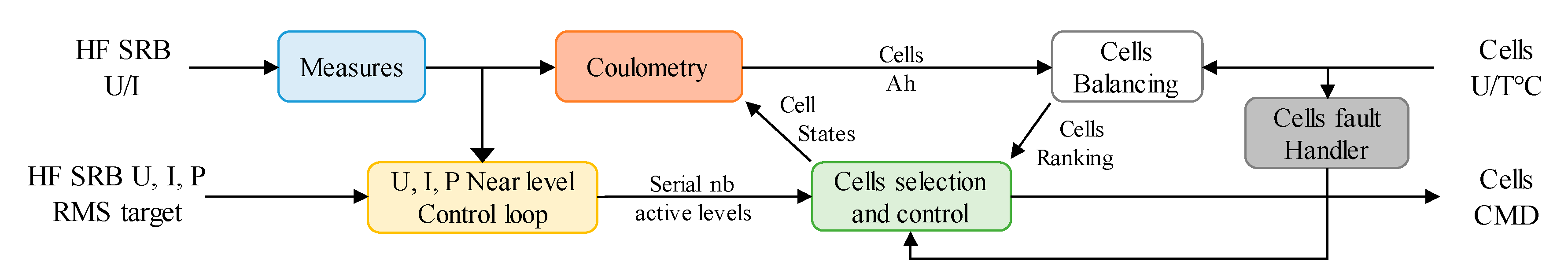
The master controller performs asynchronous control of the remote modules to make an iterative adjustment of the overall number of active levels in series. This number is determined by a nearest level control method from a reference given by a regulation loop. The reference signal is calculated in real time in order to be able to follow sudden changes in the electrical grid voltage. Each cell is activated following an order of priority established by a balancing algorithm. This one uses cell voltage and temperature measurements and cell state indicators provided by the estimation algorithms. A block diagram shows interactions between those tasks in
Figure 4.
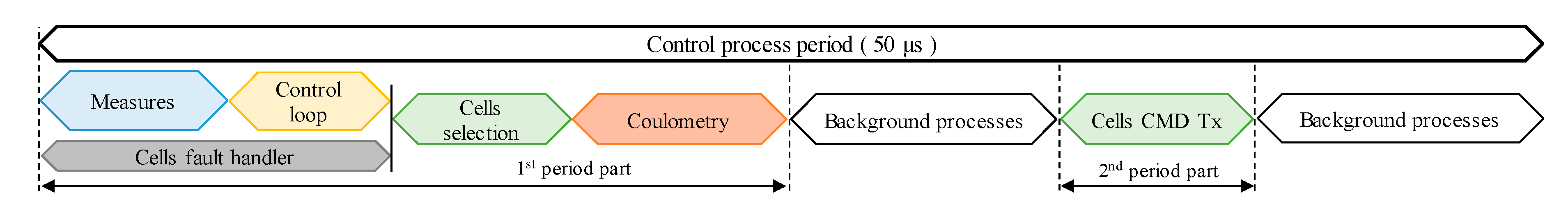
It is then necessary to organize the computation of all of those tasks in order to respect the minimum control time step mentioned before. Real-time computation of the required number of active levels requires measurements of the output voltage and current, at least at the same frequency as that used to control the series connection of the levels. Moreover, for cost-effective considerations, the overall HF SRB integrates only one current sensor. In our system, we choose to base the states of charge estimator on coulometry. It is then required to perform an individual coulometry estimation of each cell at the control frequency, in order to take into account the series/bypass state of each cell. Using the same frequency to perform all those tasks simplifies the scheduling of their sequential computation.
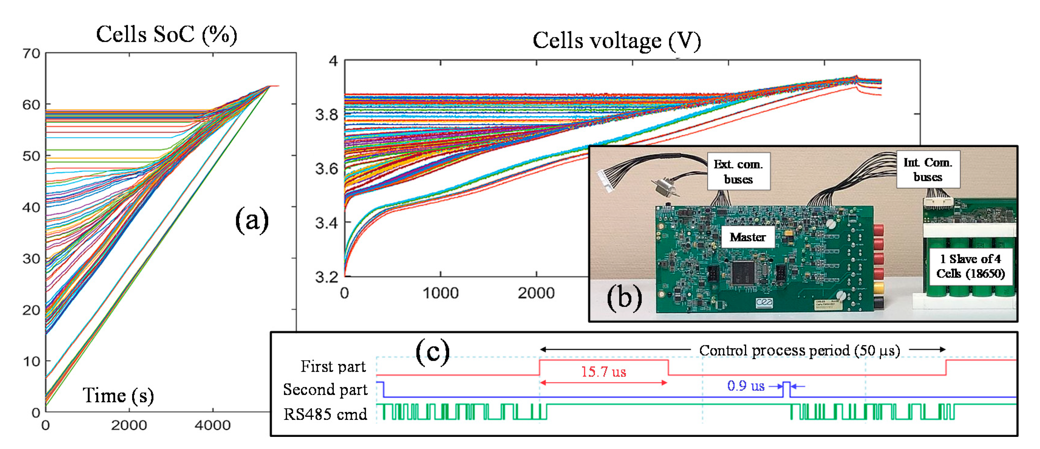
Figure 5 details the scheduling of those tasks gathered inside a process called “control process” and performed at each control period. One can see that most of the tasks are performed in the order of their dependencies, while the balancing task is performed in the background over many control periods. The control process is split into two parts. The first period part determines the command frames to send to the slaves. Its duration could have jitter due to the variability of some algorithms regarding cells selection and coulometry. The second part corresponds to the sending of the command frames. Both parts of the process are triggered by timer events in order to avoid jitter on the frequency of the command frame output.
4.2. Nearest Level Control Loop
There are two different control systems in the HF SRB’s software to manage AC voltage generation during discharge (
Figure 6) and the charge of the batteries with AC voltage (
Figure 7).
The output of each of them has a system command generator (SCG) bloc (
Figure 6) to convert a voltage command into the number of levels in series (n) to be activated at the output of the HF SRB. k
MAX is the maximum number of series cells that the system can be applied to at the same time (cells added if positive and cells removed if negative) and V
cellMax is the maximum voltage of one cell (4.2V for NMC Lithium battery). The discharge control system (DCS) includes two sub-control loops: a current limit control (CLC) to ensure that I
out amplitude never exceeds
ILIMIT, and a voltage control (VC) to ensure that V
out follows V
ref. The target AC voltage data points, which are obtained by sampling a 230VAC-50 Hz sinusoidal signal at 20 kHz, are stored in a look-up-table (LUT). The latter is then multiplied by a factor α to produce V
ref with 0 ≤ α ≤ 1. α is decreased by CLC to lower V
out when the output current I
out is too high.
The derivative part of the proportional-integral-derivative (PID) controller used in CLC has a primordial function to anticipate the variation of Iout when it lags behind Vout in the case of inductive load. As the derivative function is sensitive to the measurement noises, a low-pass filter (LPF) is added to make it a filtered PID.
In VC, the phase advance filter (PAF) compensates the delay φ introduced by the response of the HF SRB system to the command of the number of series levels to activate. Therefore, this controller makes the control loop response faster with more stability.
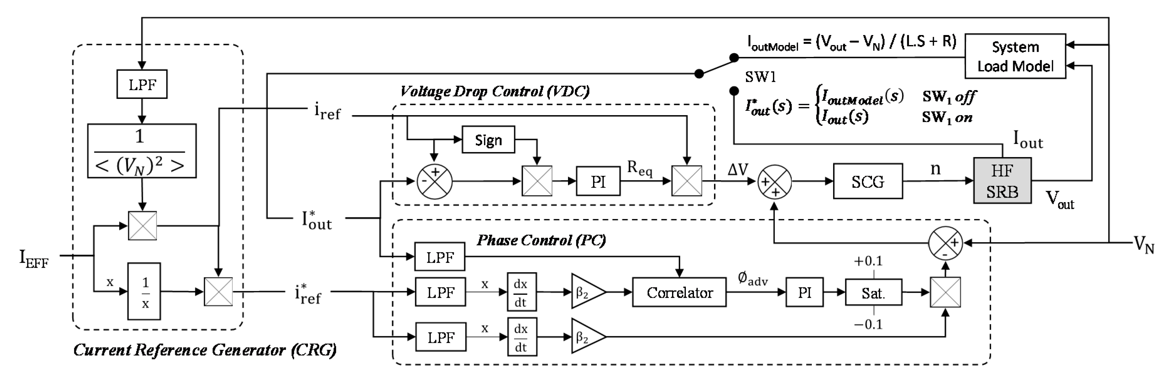
The charge control system (CCS) aims to charge the HF SRB from any electrical AC voltage sources by applying an output voltage Vout with the same pace and in phase with the charge voltage VN, while ensuring an instantaneous charge current in phase with voltages Vout and VN. As a result, the potential reactive power consumed by any inductive components in the system, such as L1 and L2, will be removed. Hence, the CCS includes three main blocs: a current reference generator (CRG) bloc, a phase control (PC) bloc and a voltage drop control (VDC) bloc. The CRG bloc generates two current reference signals obtained from VN, and then in phase with it: iref is the instantaneous current that Iout should look like (same pace and effective value IEFF) and iref^* is the normalized value of iref. The PC bloc determines and controls the delay ∅adv of the feedback current Iout^* with respect to iref^* (simultaneously VN) to make the charge current and voltage in phase. The LPF is a first-order filter where τ = 100 µs.
Finally, the VDC bloc controls the differential voltage ∆V between VN and Vout to keep Iout^* close to iref. To obtain ∆V, the control loop estimates the equivalent resistor Req between batteries and the AC charger that includes batteries ESR, inductors internal resistance, wire resistance and so on. In practice, VN is not directly connected to Vout at the start-up of the control system to avoid short-circuiting and damaging the charger and the HF SRB system. The solution is to synchronize VN and Vout when Iout = 0 A (SW1 off) and to make VN’s amplitude slightly higher than Vout’s one to allow current flows from AC charger to HF SRB after switching on SW1. To do this, Iout^* is first equal to the modelled current IoutModel until |∅adv| < 0.01—the necessary condition to switch on the power relay SW1—and then uses Iout as a feedback input current.


