
SPWM Inverter Control for Wireless Constant Current and Voltage Charging


Key Laboratory of Transport Industry of Marine Technology and Control Engineering, Shanghai Maritime University, Shanghai 201306, China
*
Author to whom correspondence should be addressed.
World Electr. Veh. J. 2023, 14(4), 111; https://0-doi-org.brum.beds.ac.uk/10.3390/wevj14040111
Submission received: 5 March 2023
/
Revised: 23 March 2023
/
Accepted: 7 April 2023
/
Published: 14 April 2023
(This article belongs to the Topic Coil, Circuit and Control Designs for Future Wireless Power Transfer Systems in Electric Vehicle Applications)
Abstract
:Constant current (CC) and constant voltage (CV) charging of batteries is a crucial research area in the practical implementation of wireless power transfer (WPT) systems. The typical charging process of a battery starts from the constant current mode. As the battery’s voltage increases, the charging mode switches to the constant voltage mode. During charging, the equivalent load resistance of the battery will vary with the charging time, and the equivalent load resistance will affect the charging current or voltage and system’s efficiency. In this study, an adaptive wireless charging method of CC-CV is proposed based on sinusoidal pulse width modulation (SPWM) inverter control. The proposed WPT circuit detects the load variation by measuring the parameters of load voltage and load current, and accurately controls the system output current or voltage by adjusting the modulation depth of the SPWM inverter on the primary side. When there is relative motion between the transmitting coil and the receiving coil, the sharp change in coupling coefficient directly affects the system’s output voltage and output current, leading to output fluctuations and instability. To solve this problem, a method for estimating the coupling coefficient is proposed which estimates the coupling coefficient during the charging process by measuring system parameters. Then, the controller on the primary side adjusts the modulation depth of the SPWM inverter circuit based on the estimated new coupling coefficient, so that the system can still achieve constant current and constant voltage charging under displacement or distance changes. In this study, the CC mode output current during battery charging was set to 0.75 A, and the CV mode output voltage was set to 12 V. Simulation and experimental results demonstrate the validity and accuracy of the proposed control method.
1. Introduction
Electricity transmission is crucial for human production and daily life. Wireless power transfer (WPT) technology enables the transmission of electric energy from a power source to a load without direct electrical contact. WPT technology has rapidly developed with the advancements in modern industry and technology and is widely utilized in various fields, such as biomedical equipment, aerospace, consumer electronics, manufacturing facilities, and electric vehicles [1,2,3,4].
As a sustainable transportation option, electric vehicles (EVs) are becoming increasingly popular worldwide. With the increasing demand for electric vehicles, it is important to develop efficient and reliable charging techniques for their lithium-ion batteries. There are three commonly used charging methods: constant current–constant voltage (CC-CV) charging [5], constant power charging [6,7], and pulse charging [8,9]. CC-CV charging involves controlling the charging current and voltage to keep the battery at a constant current or voltage during the charging process. Constant current charging can charge the battery faster in the early stages of charging, and constant voltage charging can fill the battery faster in the later stages of charging. Therefore, by combining constant current and constant voltage charging, charging efficiency and speed can be maximized. This charging method performs well in terms of charging speed and efficiency and can prevent overcharging and over-discharging, thereby extending the battery’s lifespan.
In contrast, constant power charging and pulse charging have faster charging speeds but are more prone to overcharging or over-discharging the battery, which can reduce its lifespan. Constant power charging involves continuously adjusting the charging current and voltage to maintain a constant charging power during the charging process. Pulse charging applies periodic high-voltage and high-current pulse signals to the battery during charging to increase the charging speed.
Although constant power charging and pulse charging allow faster charging speeds, they require more complex control strategies to avoid negative impacts on the battery. In comparison, CC-CV charging has a simpler and more reliable control strategy, can adapt to different types of batteries, and can effectively protect the battery.
Therefore, in many applications, CC-CV charging is still one of the most commonly used charging methods, especially in the electric vehicle and renewable energy storage fields. By accurately controlling the charging current and voltage, CC-CV charging can achieve efficient, safe, and reliable battery charging.
Over the years, electric vehicles known for their eco-friendliness and high efficiency have been increasingly replacing traditional fuel-based vehicles, leading to a surge in the interest in wireless charging technologies for electric vehicles. Lithium-ion batteries are now widely used as energy storage units in electric vehicles [10]. Figure 1 illustrates the charging process of a lithium battery, which begins with the CC mode and switches to the CV mode as the battery voltage increases [11]. The dynamic changes in the equivalent load resistance of the battery during the charging process can affect the charging current, charging voltage, and system transmission efficiency. Hence, a closed-loop control scheme is crucial for achieving precise control of CC and CV charging in the wireless charging system [12].
The output of a WPT system is influenced by compensation parameters, operating frequency, and load conditions. Typically, compensation parameters and operating frequency are constant, while the system output varies with load conditions. The use of DC-DC converter, a variable frequency or phase-shifted full-bridge inverter, or an impedance matching network are the main control methods for CC and CV wireless charging systems [13,14,15]. Using a buck/boost converter for DC-DC conversion can potentially have a negative impact on the system transmission efficiency and may also result in increased weight or cost [13]. If the operating frequency of the system deviates significantly from the optimal frequency, adjusting the frequency may result in a reduction in the system’s power transmission capacity [14]. Phase-shift control is a technique that modifies the duty cycle of the inverter output voltage by varying the phase difference between the front and rear sections of the inverter, thereby adjusting the system output. This method is effective at compensating for the reactive power of the system when it operates at the resonant frequency. However, when using impedance matching, a large array of capacitors or inductors is required, which can increase the weight, size, and control complexity of the system [15].
In two papers [14,15], the system in question utilizes a DC-DC converter on the primary side and employs frequency conversion or phase-shift control for the full bridge inverter on the primary side to achieve CV output through impedance-matching control. In another two studies [16,17], to achieve CV output, a chopper control link such as a buck or boost converter is added to the secondary circuit. While these systems have achieved good CV output, the addition of extra circuits reduces the transmission efficiency of the system and increases the control complexity. In the studies [18,19], phase shift control was utilized to achieve CV output, but the circuit may fail to meet the output voltage requirements when the load varies significantly. Another study [20] utilized a PWM scheme with a phase-locked loop (PLL) control method. However, the circuit-input impedance needs to be inductive throughout the entire load variation range, which results in an increase in reactive power loss. In the studies [21,22], the system achieved CC and CV output through frequency-conversion control at two different operating frequencies. However, changing the frequency increases the complexity of hardware circuit design.
Many practical applications of WPT systems suffer from misalignment or variations in transmission distance between the transmitting and receiving coils. This can cause a significant change in the coupling coefficient, leading to instability in the output voltage and current. To address this issue, many researchers have investigated methods to identify the coupling coefficient. One such method proposed in [23] uses a switched capacitor, but its implementation in practical applications is challenging. In [24], a dynamic method that only requires parameters from the receiving end was analyzed, but its measurement complexity and uncertainty are high due to the high harmonics of the rectified current. In [25], the coupling coefficient was estimated by analyzing the relationship between the duty cycle of the buck–boost circuit and the coupling-coefficient change. However, this method results in two solutions for the coupling coefficient, and obtaining the true value from the two solutions using the duty cycle of the buck circuit is inefficient. Another method proposed in [26] identifies the coupling coefficient using the input impedance equation, which offers a single solution and avoids the double-solution problem encountered in [25]. This paper proposes a method for estimating the coupling coefficient when the coil is misaligned or the transmission distance changes during charging, and designs a CC/CV output adaptive control flow based on the coupling-coefficient estimation.
The SPWM inverter is a type of inverter used to convert DC voltage into AC voltage. It works by generating a sequence of high-frequency pulses whose widths are modulated in such a way that the average voltage waveform obtained is a sine wave. This makes the SPWM inverter an ideal solution for applications that require a high-quality sine wave input. One of the main advantages of SPWM inverters over other types of inverters is that they provide a high-quality sine wave output with low harmonic distortion, which is essential for many electrical devices. Additionally, SPWM inverters are efficient, reliable, and can be easily controlled, making them ideal for use in various applications.
This paper proposes a WPT system based on SS compensation with an SPWM inverter circuit. To achieve CC/CV output, the modulation depth of the inverter circuit is controlled within a certain range as the load varies. Specifically, the system operates in CC mode with an output current of 0.75 A when the load voltage is below the maximum charging voltage of 12 V. Once the load voltage reaches 12 V, the system switches to CV mode, and charging ends when the load current is less than the charging end current. The contributions of this paper are as follows:
(1) A method to realize CC/CV output of WPT system under the control of SPWM inverter is proposed.
(2) A mathematical model between load voltage (and load current ) and the modulation depth of SPWM inverter was built.
(3) An adaptive control flow of CC/CV output was designed.
(4) A method for coupling-coefficient estimation during charging is proposed.
(5) A CC/CV adaptive output strategy for WPT systems with coupling-coefficient estimation was designed.
(6) An experimental circuit of WPT with S-S compensation with CC/CV output was built, and the proposed model and method were verified.
This paper is organized as follows. Section 2 presents an analysis of the proposed WPT circuit, including the derivation of the relationship between modulation depth and CC/CV output condition, estimating coupling coefficients and the controlling scheme. In Section 3, the proposed control scheme is validated through simulations. Section 4 evaluates the effectiveness of the proposed method through experimental results. Finally, Section 5 provides the conclusions of this study.
2. System Analysis
2.1. Theoretical Model of S-S WPT Circuit
The WPT system comprises a transmitter and a receiver, which are connected through magnetic coupling to transfer energy via an alternating magnetic field. The transmitter employs a full bridge inverter circuit to convert DC voltage to AC voltage, and the receiver uses a full bridge rectifier circuit to convert AC voltage back to DC voltage.
To efficiently transfer electrical energy in the WPT system using an alternating magnetic field, compensation elements (usually capacitors) are added to the transmitting and receiving coil ends to reduce reactive power [11,27,28,29,30,31,32,33,34,35]. The basic compensation topology of the WPT system can be classified into four types based on the series or parallel connection between the capacitor and the transmitting/receiving coil. These four types are: series–series (S-S), series–parallel (S-P), parallel–parallel (P-P), and parallel–series (P-S) [27,28,29]. Among them, the S-S compensation circuit is widely used due to its simple structure, and the selection of capacitance is not affected by load and coupling conditions when the system operates at resonance frequency, hence the popularity of this circuit [11,29,30,31].
Figure 2 illustrates the typical circuit diagram of S-S WPT [11,29,31], which consists of a full bridge inverter circuit (), a transmission coil (), a receiving coil (), a full bridge rectifier circuit (), and two compensation capacitors ( and ). The transmitter coil and the compensation capacitor form the primary-side resonant circuit, and the receiver coil and the compensation capacitor form the secondary-side resonant circuit. M is the mutual inductance between the transmitter coil and the receiver coil . and are the rms values of the resonant current on the primary side and the secondary side, respectively. and are the internal resistance of the transmitter coil and the receiver coil , respectively, and is the filter capacitor. The DC voltage is the input voltage of the full-bridge inverter circuit. is the rms value of the output voltage of the full-bridge inverter circuit. is the rms value of the input voltage of full-bridge rectifier circuit. is the load current. is the load voltage.
The following equations can be derived based on Kirchhoff’s voltage law (KVL):
where is the operating angle frequency of the system satisfying . is the operating frequency of the system. and are the equivalent impedances of the transmitting and the receiving, respectively:
Typically, and are complex numbers. However, when the system operates at the resonant frequency, and can be represented as pure resistance, with , where is the equivalent AC resistance between the rectifier bridge circuit and the DC load. According to the fundamental equivalent principle, and are satisfied with [34]:
It can be intuitively inferred that if the DC load is known, the corresponding DC load voltage or current can be adjusted by controlling .
2.2. Analysis of SPWM Single-Phase Inverter Circuit
In the single-phase inverter circuit, PWM modulation is often used to control the switches (). There are square wave modulation and SPWM modulation among the PWM modulation methods. Although the square-wave modulation has a high DC utilization rate, the harmonic content of output voltage is also high. The output voltage waveform of the inverter circuit using SPWM modulation is a series of rectangular pulses with the same amplitude and unequal width. The pulse width varies according to the sine law. When it acts on the inertial component, the output is equivalent to a sine wave. Its benefits include a reduced level of harmonic distortion and a high degree of linearity in voltage regulation.
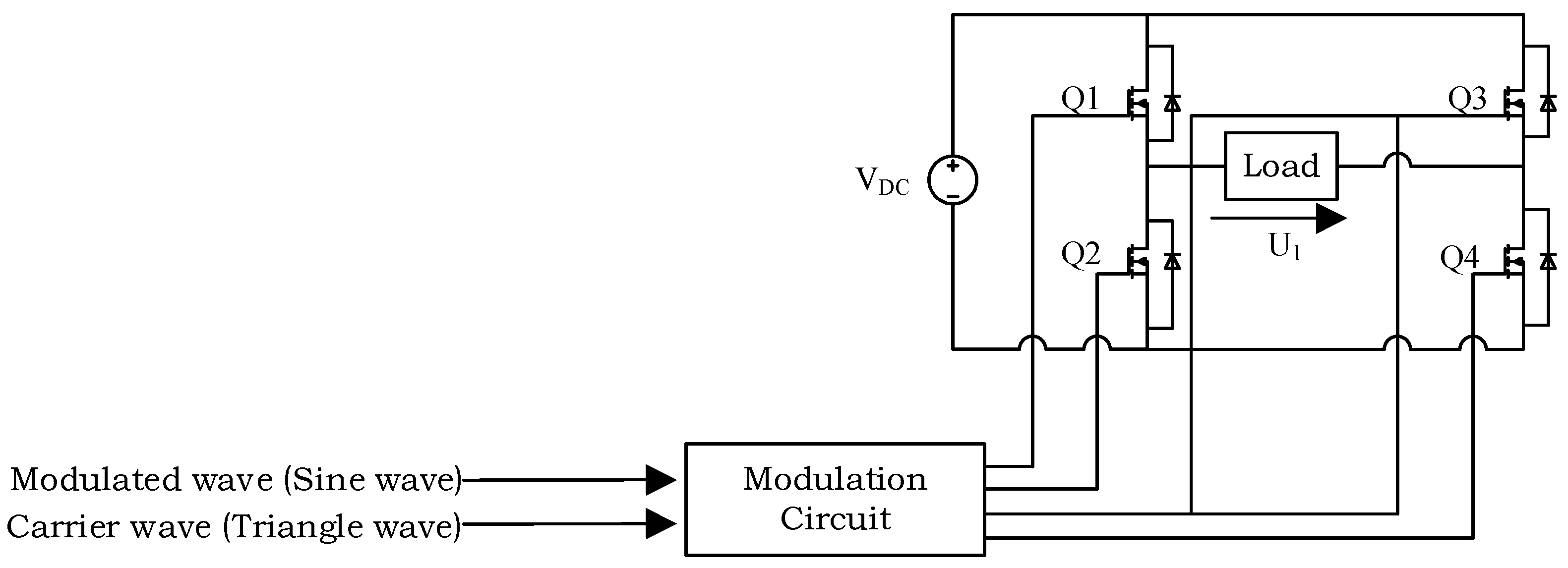
The SPWM single-phase inverter circuit is shown in Figure 3. The SPWM signal is generated by comparing the sine wave of the modulation wave with the triangle wave of the carrier wave. In the part where the sine wave is larger than the triangle wave, the switches and are on. At the time where the sine wave is smaller than the triangle wave, the switching devices and are on. The output voltage of the inverter circuit is continuously switched between positive and negative as the switches turn on at carrier frequency.
When the amplitude of the sine wave is , the amplitude of the triangle wave is , the modulation depth is defined as , and 0 < ≤ 1, then the output voltage of inverter circuit can be expressed as:
where is the rms value of the voltage of the inverter circuit. It can be seen intuitively that the output voltage of the inverter circuit can be adjusted by controlling the modulation depth .
In practical applications, microcontrollers (such as stm32 series controllers) are usually used to generate a SPWM signal, and the external drive circuit drives the on–off of switches .
2.3. Analysis of CC/CV Output
When the WPT system operates in the resonant frequency, the impedance angle is zero—that is, the imaginary part of the impedance is zero. The impedance can be represented as pure resistance, with . Therefore, the resonant frequency of the resonant circuits on the primary side and secondary side are designed to be same, and the system is operated at the resonant frequency —that is:
When the WPT system is operated in CC mode, the relationship between load current and modulation depth in the SPWM inverter is:
Further, it can be expressed as follows:
where is the output current required in CC mode, and is the modulation depth in CC mode. From Equation (10), when the load varies, the modulation depth can be adjusted so that the system output current tracks the output current required by the CC mode, and increases as increases. When the coil internal resistance and are ignored, Equation (10) can be further simplified to:
It can be seen in Equation (11) that when the internal resistance of the coil is ignored and the system operates at resonant frequency, the WPT circuit with S-S compensation can realize CC charging independent of load [32].
When the WPT system is operated in CV mode, the relationship between load voltage and modulation depth of SPWM inverter is as follows:
Further, it can be expressed as follows:
where is the output voltage required in CV mode, and is the modulation depth in CV mode. Similarly, when the coil’s internal resistances, and , are ignored, Equation (13) can be further simplified to:
From Equations (13) and (14), when the load varies, the modulation depth can be adjusted so that the system output voltage tracks the output voltage required by the CV mode, and decreases as increases.
The system’s load power is:
The system’s input power is:
The system’s transmission efficiency can be expressed as:
If the coil internal resistances and are ignored, transmission efficiency, , can be simplified as:
In Equation (18), the DC input voltage , mutual inductance M, and operating angle frequency ω of the WPT system are fixed. Therefore, when the system operates in CC mode, the transmission efficiency is determined by the modulation depth and the system output current , where is constant. Equation (11) indicates that the modulation depth is constant when the system operates in CC mode, resulting in an almost constant efficiency . When the system operates in CV mode, the transmission efficiency is determined by the modulation depth m, the system output voltage , and the load , where is constant. Taking partial derivatives of with respect to and yields:
Compare the absolute values of two partial derivatives, yielding:
As is less than or equal to 1, and is typically greater than 1, Equation (21) is less than 1, which means . Therefore, dominates in the denominator of Equation (18). As a result, the efficiency in CV mode gradually decreases with an increase in .
2.4. Adaptive Control Strategy for CC-CV Output of WPT System
During battery charging, the WPT system operates in CC mode if the battery voltage is lower than the set voltage, causing the voltage to rise. Once the battery voltage reaches the preset level, the system switches from CC mode to CV mode, resulting in a decrease in charging current. Charging ends once the charging current falls below the preset end current. The equivalent load resistance of the battery changes over time during the charging process, which can affect the charging voltage or current. As noted in literature [36], a properly designed WPT system should ensure output stability. Therefore, in the event of a variation in the equivalent load resistance, a well-designed WPT system should be capable of automatically adjusting the system’s parameters to enable the output current in CC mode to follow the required and the output voltage in CV mode to follow the required . In this study, the modulation depth m of the SPWM inverter circuit is controlled to enable to track or to track . The closed-loop control structure is depicted in Figure 4.
The ARM (Advanced RISC Machine) controller is a type of microcontroller based on the ARM architecture. The ARM processor is designed to be 32-bit, but it also supports a 16-bit instruction set. In addition, the ARM processor has advantages such as low power consumption, high performance, high reliability, easy development, and good flexibility. The STM32F103ZET6 is a microcontroller based on the ARM Cortex-M3 core, developed by ST Microelectronics. It has the advantages of high performance, low power consumption, high reliability, and easy development. The microcontroller has 512 KB of built-in flash memory and 64 KB of SRAM memory, and is equipped with multiple timers, an ADC, a DAC, and other modules. Therefore, in this study, the STM32F103ZET6 was chosen as the controller.
In Figure 4, the ARM controller at the receiver calculates the load by detecting the load current and voltage . Then, the is fed back to the ARM controller at the transmitter through wireless communication. The transmitter ARM controller tracks the required output current or the required output voltage by calculating the modulation depth m of SPWM inverter circuit through Equation (10) or Equation (13).
The flow of the control scheme proposed in this paper is shown in Figure 5, including the following steps:
- (1)
- Make the WPT circuit operate at the resonant frequency ;
- (2)
- Detect whether < ; if < , start the control procedure. Otherwise, close the S-S WPT circuit.
- (3)
- Detect and , and calculate .
- (4)
- According to Equation (10), adjust the modulation depth m, so that = , and the control system operates in CC mode.
- (5)
- Judge whether = is true; if it is true, execute step (6); if not true, repeat steps (3)–(4).
- (6)
- Re-detect and , and calculate .
- (7)
- According to Equation (13), adjust the modulation depth m, so that = , and the control system operates in CV mode.
- (8)
- Repeat steps (6) and (7) until .
- (9)
- When , the charging is completed, and close the S-S WPT circuit.
2.5. Coupling-Coefficient Estimation
The WPT system exhibits loose coupling, which means that variations in the alignment of the transmitting and receiving coils, or changes in transmission distance, can lead to significant fluctuations in the coupling coefficient k. These fluctuations in k can directly impact the output voltage or current of the system, resulting in unstable performance. To maintain CC/CV output, it is essential to estimate the coupling coefficient k. This section examines the method of estimating the coupling coefficient based on circuit parameters, utilizing Figure 2 as a reference.
The rms value of voltage of receiving coil can be derived as:
Assuming that is constant, and combined with Equation (4), it can be seen that is also constant. However, any changes in the mutual inductance M would cause a variation in the ratio of . Therefore, combining Equations (4) and (22) can estimate mutual inductance M.
can be calculated as:
Mutual inductance M can be derived as:
Combining Equation (5) with Equation (6), it can be deduced that:
Substituting Equation (25) into Equation (24), mutual inductance M can be further deduced as:
The relationship between mutual inductance M and coupling coefficient k is as follows:
Equation (27) reveals that the coupling coefficient k is influenced by both the self-inductance of the transmitting and receiving coils and their mutual inductance. Specifically, the coupling coefficient k is directly proportional to the mutual inductance M and inversely proportional to the self-inductance or of the coils. Thus, when the sizes, dimensions, and numbers of turns of the transmitting and receiving coils are fixed, the coupling coefficient k depends solely on the mutual inductance M between the coils. In other words, as the mutual inductance M increases, so does the coupling coefficient k. Therefore, the coupling coefficient k can be derived as:
When the coil is misaligned or the transmission distance changes, the CC/CV output of the WPT system can be achieved by utilizing the coupling coefficient k calculated using Equation (28).
If the internal resistances and of the transmitting and receiving coils are ignored, then one solution of Equations (26) and (28) is 0, and the other solution can be expressed as follows:
Thus, the sign “±” in Equations (26) and (28) should be interpreted as “+” instead.
2.6. Control Strategy Based on Coupling-Coefficient Estimation
When the coils are misaligned or the transmission distance varies, the coupling coefficient k will change accordingly, making it impossible for the system to achieve CC/CV output. To address this issue, as depicted by Equation (28), we can estimate the coupling coefficient k by measuring the output parameters of the circuit and known system parameters, and then use this estimated value to adjust the desired modulation depth m for the CC/CV mode, as shown in Equation (10) or Equation (13) after substitution.
Figure 6 illustrates the CC/CV control process utilizing coupling-coefficient estimation. After establishing communication between the transmitter and receiver, the receiver controller calculates the load resistance by measuring the load voltage and the load current , and also detects changes in and . Any changes detected are then fed back to the transmitter controller. Using Equation (28), the transmitter determines the coupling coefficient k and subsequently determines the CC/CV modulation depth m using Equation (10) or (13). The transmitter controller automatically adjusts m to ensure that tracks or tracks .
Based on Equation (9), as the coupling coefficient k varies, the output current in CC mode also varies. Therefore, at this stage, the WPT system fails to achieve the required output current in CC mode. Equation (10) indicates that the system can achieve the required output current in CC mode by adjusting the modulation depth m. To adjust the modulation depth m, the first step is to estimate the coupling coefficient k of the system when the coils are misaligned or the transmission distance varies. Subsequently, by substituting the newly acquired coupling coefficient k into Equation (10), the modulation depth m that satisfies the requirement of the CC mode for the output current can be determined.
Figure 7 illustrates the process for adjusting the modulation depth m in CC mode when there is a misalignment of the coil or a change in transmission distance. The circuit should be connected based on the ideal circuit, and when the coupling coefficient k changes, measurements of the output voltage , output current , and input voltage of the transmitting coil should be taken. From these measurements, the load can be calculated. Using Equation (28), the coupling coefficient k can be estimated. Next, the required modulation depth m can be calculated using Equation (10), and the controller can adjust the modulation depth m to ensure that the output current tracks the required current for CC mode.
Equation (12) implies that changes in the coupling coefficient k will cause a corresponding change in the output voltage in CV mode, making it impossible for the WPT system to meet the required output voltage in CV mode. However, Equation (13) shows that adjusting the modulation depth m can enable the system to satisfy the required output voltage in CV mode. To determine how to adjust the modulation depth m, the first step is to estimate the coupling coefficient k of the system when there is misalignment of the coils or variations in transmission distance. Then, this new coupling coefficient k can be substituted into Equation (13) to obtain the modulation depth m required to achieve the output voltage in CV mode.
Figure 8 illustrates the process for adjusting the modulation depth m in CV mode when there is a misalignment or a change in transmission distance of the coil. The first step is to connect the circuit based on the ideal circuit. Then, when there is a change in the coupling coefficient k, the output voltage , output current , and input voltage of the transmitting coil are measured. Using the output voltage and output current , the load is calculated, and the coupling coefficient k is estimated at this time using Equation (28). Equation (13) is used to calculate the required modulation depth m, and the controller adjusts the modulation depth m to ensure that the output voltage tracks the required for the CV mode.
3. Simulation of the Wireless Charging System
The circuit model of the WPT system was established in MATLAB/Simulink, and the CC-CV charging was simulated under the condition of coupling coefficient and the load of 10–25 Ω. The system parameters are shown in Table 1.
The MATLAB/Simulink model established includes an SPWM inverter circuit, a resonant circuit, a rectifier circuit, a sinusoidal signal generator, a triangular wave-signal generator, an amplitude comparator, and a signal inverter, as shown in Figure 9. During the model operation, the CC output is conducted when the load is 10–15 Ω and the required is 0.75 A. When the is 16–25 Ω, the required for CV output is 12 V.
The amplitude of the triangle wave signal generator was set as unit 1. The amplitude of the sinusoidal signal generator was calculated by Equations (10) and (13) according to the value of the load . The signals generated by the sinusoidal signal generator and the triangle wave signal generator were compared by the amplitude comparator to generate the SPWM signal, which controlled the switches and . The signal reverser reverses the generated SPWM signal and controls the switches and . The DC power is first converted to high-frequency AC power by the SPWM inverter circuit. This high-frequency AC power is then fed into the transmitting coil via the compensation capacitor , which generates a high-frequency alternating magnetic field when excited. The receiving coil and compensation capacitor generate AC power through magnetic coupling induced by this high-frequency alternating magnetic field. The generated AC power is then rectified by the rectifier circuit, converting it to DC power. In this way, the wireless power transfer is achieved.
Figure 10 shows that the increases from 10 to 25 Ω, and simulation results of and are compared with the theoretical values. The simulation results are in good agreement with the theoretical values, indicating that the system has good CC and CV output performance, which verifies the accuracy of the model and method. In CC mode, tracks , and increases with increases of . In CV mode, tracks , and decreases as increases. The simulation results of and are slightly lower than the theoretical values, because the impedance of the rectification bridge circuit and load is equivalent to a pure resistance, which will produce error in the design of system parameters. Overall, the error is within the acceptable range.
4. Experimental Verification
To further verify the method, a resonant WPT experimental circuit based on S-S compensated was designed and built, as shown in Figure 11. The system’s parameters are shown in Table 1. The parameters of coils and the compensation capacitor are measured by a LCR meter (GW Instek: LCR821). The ratio of coil turns at the transmitting and receiving ends is 17:17. The inner diameter and outer diameter of coil are 12 and 22.5 cm, respectively. The operating frequency of the system is 43.2 kHz, and the DC input voltage is 12 V. The 0.75 A constant current output is achieved when the load varies from 10 to 15 Ω, and the 12 V constant voltage output is achieved when the load varies from 16 to 25 Ω. Initially, the CC-CV charging strategy based on SPWM inverter control was tested at a transmission distance of 3 cm between the transmitting and receiving coils. Subsequently, the proposed CC-CV charging strategy based on coupling-coefficient estimation was evaluated at a transmission distance of 4 cm. The coupling coefficient between the coils was calculated to be 0.5032 using Inca [37] software at a transmission distance of 3 cm, based on the coil parameters in Table 1. When the transmission distance was increased to 4 cm, the proposed coupling-coefficient-estimation method was used to estimate the new coupling coefficient, which was found to be 0.4257.
4.1. System Experimental Device
The experimental WPT system is shown in Figure 11. The system adopts STM32F103ZET6 as the main control chip. The system circuit mainly includes a full-bridge inverter circuit, a resonant circuit, a rectifier filter circuit, and a DC-voltage-acquisition circuit. The amplitude of a control signal generated by the microcontroller is only 5 V, so the driver circuit is required to amplify the control signal so that it can drive the MOS transistors to operate normally. Two half-bridge drive chips IR2110 are used in the drive circuit to form a full-bridge driver. The full bridge inverter circuit converts DC power into AC power to provide a high-frequency excitation source for the transmitter. The MOS transistors adopt FQPF5N60C, which has the characteristics of a high voltage resistance value and high switching frequency. The full-bridge rectifier circuit converts AC power into the DC power to charge the DC load. The diode adopts HER508, which has high voltage resistance, low turn-on voltage, low impedance, and other characteristics. The DC-voltage-acquisition circuit collects the voltage across the DC load. STM32F103ZET6 has its own analog-to-digital converter (ADC), which can collect analog voltage signals and convert them into digital signals for processing. However, the ADC input voltage of STM32F103ZET6 is 0 to 3.3 V, and the CV output voltage of the WPT circuit designed in this study is 12 V. Therefore, a DC-DC conversion circuit is required to step down the 12 V voltage to below 3.3 V, so that the STM32F103ZET6 ADC can be used to sample and process.
The core of the system software is the compilation of the SPWM wave program and ADC sampling program. The software of SPWM wave design is to form an array of data generated by the software of the SPWM data table, and the data are stored in the microcontroller and generate the SPWM wave by calling the array. The advanced timer TIMER1 of STM32F103ZET6 generates two sets of complementary PWM signals. The ordinary timer TIMER3 controls the sine wave period. Within each sine wave cycle, the generated sine table is assigned to the TIM1_CCR1 register in order to generate SPWM wave.
The time from the STM32 controller’s ADC sampling to the SPWM control signal output is in the milliseconds, about 10–20 ms, and the change time of the equivalent resistance during battery charging is typically above the second level [38]. This means that during battery charging, the changing speed of the battery equivalent resistance is much slower than the STM32 controller’s processing speed, from ADC sampling to the SPWM control signal output. Therefore, during the battery charging process, the STM32 controller can capture the change trend of the equivalent resistance by continuously sampling and storing data, and then use these data for more accurate control.
4.2. S Verification of the Proposed Control Method
4.2.1. Validation of CC-CV Charging Strategy Based on SPWM Inverter Control
With the ideal alignment, the experiment was carried out with the transmission distance of 3 cm, and the circuit was operated at the resonant frequency . We prepared 10 to 25 Ω resistors with an interval of 1 Ω. When the was 10–15 Ω, we adjusted the modulation depth m according to Equation (10) so that = , and the control system was operated in CC mode. When the was 16–25 Ω, we adjusted the modulation depth m according to Equation (13) so that =, and the control system was operated in CV mode. Figure 12 shows the adjustment process of modulation depth varying with the load . In Figure 12, when the system operates in CC mode, the modulation depth gradually increases as the load increases; and when in CV mode, the modulation depth decreases as the load increases. These results agree with the theoretical analysis of (10) and (13).
The experimental waveforms for the current of the transmitting coil and the current of the receiving coil are illustrated in Figure 13. As is evident in Figure 13, In CC mode, the current of the transmitting coil increases as the load increases, and the current of the receiving coil remains basically unchanged. In CV mode, the current of the transmitting coil remains basically constant, but the current of the receiving coil decreases as the load increases.
Figure 14 shows the comparison between the experimental results and the theoretical values. In CC mode, tracks the required , and increases as increases. In CV mode, tracks required , and decreases as increases. The experimental results verify the validity of the proposed method. The results show that the proposed method is suitable for battery charging, and the adjustment of modulation depth m is crucial for tracking in CC charging mode and tracking in CV charging mode.
In Figure 14, it can be observed that although there are deviations between the experimental results and theoretical values, the overall trend is consistent, which confirms the accuracy of the model and method used. The experimental values of and are slightly lower than the theoretical values due to the fact that the rectifier bridge circuit and load impedance can be approximated as a pure resistance according to Equation (4), which can introduce errors in the design of system parameters [39,40]. Additionally, the power electronic system is not ideal; and switches, inductors, capacitors, and other resonant devices can also introduce some errors in controlling the WPT system during operation. However, these errors are considered acceptable. Regardless, the ADC sampling of the STM32 controller will also introduce a certain error.
Figure 15 presents the system efficiency measured from the input to the load during the charging process. It can be observed that the system transmission efficiency, denoted as , remains relatively stable throughout the CC charging process, whereas it gradually decreases as the load resistance increases during the CV charging process. These results are consistent with the previous theoretical analysis given by Equation (18). The overall transmission efficiency of the system falls between 80% and 92%.
4.2.2. Validation of CC-CV Charging Strategy Based on Coupling Coefficient Estimation
Equation (28) reveals that the coupling coefficient k can be estimated by the ratio of and . The transmission distance between the transmitting coil and the receiving coil was varied from 1.5 to 5.5 cm. Figure 16 illustrates a comparison between the estimated coupling coefficient k and the Inca-calculated value at different transmission distances. As depicted in Figure 16, the estimated coupling coefficient k obtained using Equation (28) is largely consistent with the Inca-calculated value, indicating that estimating the coupling coefficient through the ratio of and is practical and highly accurate. This satisfies the design requirements completely.
When the transmission distance between the transmitting and receiving coils was increased from 3 to 4 cm, the coupling coefficient k was estimated to be 0.4257 using Equation (28). This new value of k was then used to recalculate and adjust the required modulation depth m for the system to operate in CC/CV mode, by substituting it into either Equation (10) or (13). The experimental and theoretical values of the system’s output current and output voltage were compared and presented in Figure 17. As evinced in Figure 17, the required output current of the system in CC mode is 0.75 A, and the required output voltage in CV mode is 12 V. The system operates in CC mode for loads between 10 and 15 Ω, and shifts to CV mode for loads between 16 and 25 Ω.
5. Conclusions
This paper presents a wireless charging system that can adapt to changes in load by controlling the modulation depth of the SPWM inverter circuit. The system uses an S-S basic compensation structure to achieve both CC and CV charging when the load changes, and this is determined by detecting the load voltage and current. The modulation depth of the inverter circuit is adjusted to achieve the desired CC or CV output. In addition, we proposed a method for estimating the coupling coefficient and designed a CC/CV control strategy that employs this estimation method. If external disturbances result in coil misalignment or changes in the transmission distance, which affect the mutual inductance between the coils, the proposed coupling-coefficient-estimation method is utilized to estimate the new coupling coefficient. The controller then adjusts the modulation depth of the SPWM inverter to achieve CC/CV output for the system. The proposed method is mathematically simple and easy to implement—requiring no additional topology. The feasibility of the method was demonstrated through theoretical analysis and simulation, and its effectiveness and accuracy were further verified through experiments. The study also analyzed the sources of error in the system.
Author Contributions
Conceptualization, K.S. and W.N.; methodology, K.S. and W.N.; software, K.S.; validation, K.S. and W.N.; formal analysis, K.S. and W.N.; investigation, K.S. and W.N.; resources, K.S.; data curation, K.S.; writing—original draft preparation, K.S.; writing—review and editing, W.N.; visualization, K.S.; supervision, W.N. All authors have read and agreed to the published version of the manuscript.
Funding
This research received no external funding.
Data Availability Statement
Not applicable.
Conflicts of Interest
The authors declare no conflict of interest.
Nomenclature
| WPT | Wireless power transfer |
| CC | Constant current |
| CV | Constant voltage |
| SPWM | Sinusoidal pulse width modulation |
| SPWM inverter circuit modulation depth | |
| Switches of SPWM inverter | |
| Diodes of full-bridge rectifier | |
| Transmitting coil (H) | |
| Receiving coil (H) | |
| Resonant capacitor of the transmitting coil (F) | |
| Resonant capacitor of the receiving coil (F) | |
| Coupling coefficient | |
| M | Mutual inductance (H) |
| System operating angle frequency (rad/s) | |
| Resonant angle frequency (rad/s) | |
| Resonant frequency (Hz) | |
| f | Operating frequency (Hz) |
| DC input voltage of SPWM inverter (V) | |
| The rms value of voltage of transmitting coil (V) | |
| The rms value of current of transmitting coil (A) | |
| The rms value of voltage of receiving coil (V) | |
| The rms value of current of receiving coil (A) | |
| Load voltage (V) | |
| Load current (A) | |
| Impedance of transmitting coil (Ω) | |
| Impedance of receiving coil (Ω) | |
| The transmission coil internal resistance is (Ω) | |
| Internal resistance of receiving coil (Ω) | |
| Equivalent resistance of the rectifier bridge circuit and the load (Ω) | |
| Load resistance (Ω) | |
| Transmission efficiency | |
| Charging voltage required for CV mode (V) | |
| Charging current required for CC mode (A) | |
| End of charge current (A) |
References
- Zhang, Y.; Chen, S.; Li, X.; Tang, Y. Design Methodology of Free-Positioning Nonoverlapping Wireless Charging for Consumer Electronics Based on Antiparallel Windings. IEEE Trans. Ind. Electron. 2022, 69, 825–834. [Google Scholar] [CrossRef]
- Shi, K.; Tang, C.; Long, H.; Lv, X.; Wang, Z.; Li, X. Power Fluctuation Suppression Method for EV Dynamic Wireless Charging System Based on Integrated Magnetic Coupler. IEEE Trans. Power Electron. 2022, 37, 1118–1131. [Google Scholar] [CrossRef]
- Kim, J.; Ryu, J.; Kim, G.; Lee, J.; Chang, S.; Lee, C.; Kim, J.; Oh, Y.; Lee, H.; Kim, J. A Proposed Fast Charging and High-Power System for Wireless Railway Trains Adopting the Input Voltage Sharing Topology and the Balancing Control Scheme. IEEE Trans. Ind. Electron. 2020, 67, 6407–6417. [Google Scholar] [CrossRef]
- Sedehi, R.; Budgett, D.; Jiang, J.; Ziyi, X.; Dai, X.; Hu, A.P.; McCormick, D. A Wireless Power Method for Deeply Implanted Biomedical Devices via Capacitively Coupled Conductive Power Transfer. IEEE Trans. Power Electron. 2021, 36, 1870–1882. [Google Scholar] [CrossRef]
- Lopes, P.; Costa, P.; Pinto, S. Wireless Power Transfer System For Electric Vehicle Charging. In Proceedings of the 2021 International Young Engineers Forum (YEF-ECE), Caparica, Portugal, 9 July 2021; pp. 132–137. [Google Scholar]
- Corti, F.; Reatti, A.; Nepote, A.; Pugi, L.; Pierini, M.; Paolucci, L.; Grasso, F.; Grasso, E.; Nienhause, M. A Secondary-Side Controlled Electric Vehicle Wireless Charger. Energies 2020, 13, 6527. [Google Scholar] [CrossRef]
- Du, J.; Sun, Y. The influence of high power charging on the lithium battery based on constant and pulse current charging strategies. In Proceedings of the 17th IEEE Vehicle Power and Propulsion Conference, VPPC 2020, Gijon, Spain, 18 November–16 December 2020. [Google Scholar]
- Fang, H.Z.; Depcik, C.; Lvovich, V. Optimal pulse-modulated Lithium-ion battery charging: Algorithms and simulation. J. Energy Storage 2018, 15, 359–367. [Google Scholar] [CrossRef]
- Majid, N.; Hafiz, S.; Arianto, S.; Yuono, R.Y.; Astuti, E.T.; Prihandoko, B. Analysis of effective pulse current charging method for lithium ion battery. J. Phys. Conf. Ser. 2017, 817, 012008. [Google Scholar] [CrossRef]
- Zhang, B.; Carlson, R.B.; Smart, J.G.; Dufek, E.J.; Liaw, B. Challenges of future high power wireless power transfer for light-duty electric vehicles: Technology and risk management. eTransportation 2019, 2, 100012. [Google Scholar] [CrossRef]
- Tran, D.H.; Vu, V.B.; Choi, W. Design of a High-Efficiency Wireless Power Transfer System With Intermediate Coils for the On-Board Chargers of Electric Vehicles. IEEE Trans. Power Electron. 2018, 33, 175–187. [Google Scholar] [CrossRef]
- Gati, E.; Kampitsis, G.; Manias, S. Variable Frequency Controller for Inductive Power Transfer in Dynamic Conditions. IEEE Trans. Power Electron. 2017, 32, 1684–1696. [Google Scholar] [CrossRef]
- Tritschler, J.; Reichert, S.; Goeldi, B. A practical investigation of a high power, bidirectional charging system for electric vehicles. In Proceedings of the 2014 16th European Conference on Power Electronics and Applications, Lappeenranta, Finland, 26–28 August 2014; pp. 1–7. [Google Scholar]
- Gyu Bum, J.; Cho, B.H. An energy transmission system for an artificial heart using leakage inductance compensation of transcutaneous transformer. IEEE Trans. Power Electron. 1998, 13, 1013–1022. [Google Scholar] [CrossRef]
- Si, P.; Hu, A.P.; Malpas, S.; Budgett, D. A Frequency Control Method for Regulating Wireless Power to Implantable Devices. IEEE Trans. Biomed. Circuits Syst. 2008, 2, 22–29. [Google Scholar] [CrossRef] [PubMed]
- Keeling, N.A.; Covic, G.A.; Boys, J.T. A Unity-Power-Factor IPT Pickup for High-Power Applications. IEEE Trans. Ind. Electron. 2010, 57, 744–751. [Google Scholar] [CrossRef]
- Li, Z.; Zhu, C.; Jiang, J.; Song, K.; Wei, G. A 3-kW Wireless Power Transfer System for Sightseeing Car Supercapacitor Charge. IEEE Trans. Power Electron. 2017, 32, 3301–3316. [Google Scholar] [CrossRef]
- Cai, H.; Shi, L.; Li, Y. Harmonic-Based Phase-Shifted Control of Inductively Coupled Power Transfer. IEEE Trans. Power Electron. 2014, 29, 594–602. [Google Scholar] [CrossRef]
- Berger, A.; Agostinelli, M.; Vesti, S.; Oliver, J.A.; Cobos, J.A.; Huemer, M. A Wireless Charging System Applying Phase-Shift and Amplitude Control to Maximize Efficiency and Extractable Power. IEEE Trans. Power Electron. 2015, 30, 6338–6348. [Google Scholar] [CrossRef]
- Qianhong, C.; Siu Chung, W.; Chi, K.T.; Xinbo, R. Analysis, design and control of a transcutaneous power regulator for artificial heart. In Proceedings of the 2008 IEEE Power Electronics Specialists Conference, Rhodes, Greece, 15–19 June 2008; pp. 1833–1838. [Google Scholar]
- Huang, Z.; Wong, S.C.; Tse, C.K. Design methodology of a series-series inductive power transfer system for electric vehicle battery charger application. In Proceedings of the 2014 IEEE Energy Conversion Congress and Exposition (ECCE), Pittsburgh, PA, USA, 14–18 September 2014; pp. 1778–1782. [Google Scholar]
- Niu, W.; Liu, J.; Chen, Z.; Gu, W. Misalignment and range adaptive wireless charging system with constant current/constant voltage output based on coupling coefficient estimation. Int. J. Circuits Syst. Signal Process. 2021, 15, 334–348. [Google Scholar] [CrossRef]
- Su, Y.G.; Zhang, H.Y.; Wang, Z.H.; Hu, A.P.; Chen, L.; Sun, Y. Steady-State Load Identification Method of Inductive Power Transfer System Based on Switching Capacitors. IEEE Trans. Power Electron. 2015, 30, 6349–6355. [Google Scholar] [CrossRef]
- Kobayashi, D.; Imura, T.; Hori, Y. Real-time coupling coefficient estimation and maximum efficiency control on dynamic wireless power transfer for electric vehicles. In Proceedings of the 1st IEEE PELS Workshop on Emerging Technologies: Wireless Power, IEEE WoW 2015, Daejeon, Republic of Korea, 5–6 June 2015. [Google Scholar]
- Dai, X.; Li, X.F.; Li, Y.L.; Hu, A.G.P. Maximum Efficiency Tracking for Wireless Power Transfer Systems with Dynamic Coupling Coefficient Estimation. IEEE Trans. Power Electron. 2018, 33, 5005–5015. [Google Scholar] [CrossRef]
- Liu, Y.Y.; Feng, H.W. Maximum Efficiency Tracking Control Method for WPT System Based on Dynamic Coupling Coefficient Identification and Impedance Matching Network. IEEE J. Emerg. Sel. Top. Power Electron. 2020, 8, 3633–3643. [Google Scholar] [CrossRef]
- Stielau, O.H.; Covic, G.A. Design of loosely coupled inductive power transfer systems. In Proceedings of the PowerCon 2000. 2000 International Conference on Power System Technology. Proceedings (Cat. No.00EX409), Perth, Australia, 4–7 December 2000; Volume 81, pp. 85–90. [Google Scholar]
- Chwei-Sen, W.; Stielau, O.H.; Covic, G.A. Design considerations for a contactless electric vehicle battery charger. IEEE Trans. Ind. Electron. 2005, 52, 1308–1314. [Google Scholar] [CrossRef]
- Chopra, S.; Bauer, P. Analysis and design considerations for a contactless power transfer system. In Proceedings of the 2011 IEEE 33rd International Telecommunications Energy Conference (INTELEC), Amsterdam, The Netherlands, 9–13 October 2011; pp. 1–6. [Google Scholar]
- Bosshard, R.; Kolar, J.W.; Mühlethaler, J.; Stevanović, I.; Wunsch, B.; Canales, F. Modeling and η-α-pareto Optimization of Inductive Power Transfer Coils for Electric Vehicles. IEEE J. Emerg. Sel. Top. Power Electron. 2015, 3, 50–64. [Google Scholar] [CrossRef]
- Zheng, C.; Lai, J.S.; Chen, R.; Faraci, W.E.; Zahid, Z.U.; Gu, B.; Zhang, L.; Lisi, G.; Anderson, D. High-Efficiency Contactless Power Transfer System for Electric Vehicle Battery Charging Application. IEEE J. Emerg. Sel. Top. Power Electron. 2015, 3, 65–74. [Google Scholar] [CrossRef]
- Qu, X.; Han, H.; Wong, S.C.; Tse, C.K.; Chen, W. Hybrid IPT Topologies With Constant Current or Constant Voltage Output for Battery Charging Applications. IEEE Trans. Power Electron. 2015, 30, 6329–6337. [Google Scholar] [CrossRef]
- Mai, R.; Chen, Y.; Li, Y.; Zhang, Y.; Cao, G.; He, Z. Inductive Power Transfer for Massive Electric Bicycles Charging Based on Hybrid Topology Switching With a Single Inverter. IEEE Trans. Power Electron. 2017, 32, 5897–5906. [Google Scholar] [CrossRef]
- Song, K.; Li, Z.; Jiang, J.; Zhu, C. Constant Current/Voltage Charging Operation for Series–Series and Series–Parallel Compensated Wireless Power Transfer Systems Employing Primary-Side Controller. IEEE Trans. Power Electron. 2018, 33, 8065–8080. [Google Scholar] [CrossRef]
- Buja, G.; Bertoluzzo, M.; Mude, K.N. Design and Experimentation of WPT Charger for Electric City Car. IEEE Trans. Ind. Electron. 2015, 62, 7436–7447. [Google Scholar] [CrossRef]
- Li, H.; Li, J.; Wang, K.; Chen, W.; Yang, X. A Maximum Efficiency Point Tracking Control Scheme for Wireless Power Transfer Systems Using Magnetic Resonant Coupling. IEEE Trans. Power Electron. 2015, 30, 3998–4008. [Google Scholar] [CrossRef]
- Niu, W.Q.; Chu, J.X.; Gu, W.; Shen, A.D. Exact Analysis of Frequency Splitting Phenomena of Contactless Power Transfer Systems. IEEE Trans. Circuits Syst. I Regul. Pap. 2013, 60, 1670–1677. [Google Scholar] [CrossRef]
- Shi, J.; Tian, M.; Han, S.; Wu, T.-Y.; Tang, Y. Electric vehicle battery remaining charging time estimation considering charging accuracy and charging profile prediction. J. Energy Storage 2022, 49, 104132. [Google Scholar] [CrossRef]
- Zhu, Q.; Wang, L.; Guo, Y.; Liao, C.; Li, F. Applying LCC Compensation Network to Dynamic Wireless EV Charging System. IEEE Trans. Ind. Electron. 2016, 63, 6557–6567. [Google Scholar] [CrossRef]
- Wang, Z.H.; Xiao, L.; Sun, Y.; Dai, X.; Li, Y. A simple approach for load identification in current-fed inductive power transfer system. In Proceedings of the 2012 IEEE International Conference on Power System Technology (POWERCON), Auckland, New Zealand, 30 October–2 November 2012; pp. 1–5. [Google Scholar]
Figure 1.
CC-CV charging curve of battery.

Figure 2.
S-S-compensated WPT circuit.

Figure 3.
The SPWM single-phase inverter circuit.

Figure 4.
The closed-loop control structure of WPT system with CC/CV output.

Figure 5.
Adaptive the control flow chart of the CC-CV output of the WPT system.

Figure 6.
CC/CV output control strategy based on coupling-coefficient estimation.

Figure 7.
Flow chart of modulation depth adjustment based on coupling-coefficient estimation in CC mode.
Figure 7.
Flow chart of modulation depth adjustment based on coupling-coefficient estimation in CC mode.

Figure 8.
Flow chart of modulation depth adjustment based on coupling-coefficient estimation in CV mode.
Figure 8.
Flow chart of modulation depth adjustment based on coupling-coefficient estimation in CV mode.

Figure 9.
The Simulink circuit model of the WPT system.

Figure 10.
Comparison between simulation results and theoretical values of CC-CV output of the WPT system based on Simulink.
Figure 10.
Comparison between simulation results and theoretical values of CC-CV output of the WPT system based on Simulink.

Figure 11.
The WPT experimental circuit based on S-S compensation.

Figure 12.
Adjustment process of modulation depth m with .

Figure 13.
The current of the transmitting coil and the current of the receiving coil.

Figure 14.
Comparison between experimental results and theoretical values.

Figure 15.
Transmission efficiency.

Figure 16.
Comparison between the estimated value of coupling coefficient k and Inca value at different transmission distances.
Figure 16.
Comparison between the estimated value of coupling coefficient k and Inca value at different transmission distances.

Figure 17.
Comparison between experimental results and theoretical values of CC-CV output based on coupling-coefficient estimation.
Figure 17.
Comparison between experimental results and theoretical values of CC-CV output based on coupling-coefficient estimation.


Table 1.
WPT system parameters.
| Parameters | Values | Parameters | Values |
|---|---|---|---|
| 12 V | 0.2 μF | ||
| 67.89 μH | 0.5 Ω | ||
| 0.2 μF | 43.2 kHz | ||
| 0.5 Ω | 10–25 Ω | ||
| 43.2 kHz | 12 V | ||
| 66.15 μH | 0.75 A |
Disclaimer/Publisher’s Note: The statements, opinions and data contained in all publications are solely those of the individual author(s) and contributor(s) and not of MDPI and/or the editor(s). MDPI and/or the editor(s) disclaim responsibility for any injury to people or property resulting from any ideas, methods, instructions or products referred to in the content. |
© 2023 by the authors. Licensee MDPI, Basel, Switzerland. This article is an open access article distributed under the terms and conditions of the Creative Commons Attribution (CC BY) license (https://creativecommons.org/licenses/by/4.0/).
Share and Cite
MDPI and ACS Style
Sun, K.; Niu, W. SPWM Inverter Control for Wireless Constant Current and Voltage Charging. World Electr. Veh. J. 2023, 14, 111. https://0-doi-org.brum.beds.ac.uk/10.3390/wevj14040111
AMA Style
Sun K, Niu W. SPWM Inverter Control for Wireless Constant Current and Voltage Charging. World Electric Vehicle Journal. 2023; 14(4):111. https://0-doi-org.brum.beds.ac.uk/10.3390/wevj14040111
Chicago/Turabian StyleSun, Kang, and Wangqiang Niu. 2023. "SPWM Inverter Control for Wireless Constant Current and Voltage Charging" World Electric Vehicle Journal 14, no. 4: 111. https://0-doi-org.brum.beds.ac.uk/10.3390/wevj14040111