
Design of Two-Axial Actuator for Controlled Vibration Damper for Large Rams
by
 , ,
, ,
Lukáš Novotný
1,* ,
,
Jaroslav Červenka
1,
Matěj Sulitka
1,
Jiří Švéda
1,
Miroslav Janota
1 and
Petr Kupka
2 1
Research Center of Manufacturing Technology, Czech Technical University in Prague, 128 00 Prague, Czech Republic
2
TOS KUŘIM–OS, a.s., 664 34 Kuřim, Czech Republic
*
Author to whom correspondence should be addressed.
Actuators 2021, 10(8), 199; https://0-doi-org.brum.beds.ac.uk/10.3390/act10080199
Submission received: 12 July 2021
/
Revised: 12 August 2021
/
Accepted: 16 August 2021
/
Published: 19 August 2021
(This article belongs to the Special Issue Vibration Control and Structure Health Monitoring)
Abstract
:Machine tool rams are important constructional elements found on vertical lathes as well as on many other machines. In most cases, a machine tool ram constitutes an assembly with significant dynamic compliance that affects the machine’s ability to achieve stable cutting conditions. There are various solutions for increasing a machine tool ram’s stiffness and damping. This paper describes an innovative concept of a two-axial electromagnetic actuator for controlled vibration dampers with high dynamic force values. The described solution is purposefully based on the use of standard electric drives. As a result, the size of the actuator is easier to scale to the required application. The solution is designed as a spacer between the end of the ram and the head. The paper presents the actuator concept, construction design, current control loop solution and experimental verification of the controlled vibration damper’s function on the test ram in detail. The presented position measurement concept will enable the use of non-contact position sensors for motor commutation as well as for possible use in vibration suppression control. Applications can be expected mainly in the field of vibration suppression of vertical rams of large machine tools.
1. Introduction
Vibration suppression actuators are usually additional devices that generally introduce an extra force into the system. This force acts against the movement (vibration), thus reducing the amount of energy accumulated in the mechanical system. The effect of actuators on vibration suppression depends on many factors. The development of active vibration suppression methods has a relatively long history, and such methods are well described in the literature and in a number of articles. A very comprehensive overview of the state of the art can be found in publications [1,2,3]. There are also various energy harvesting methods with great potential for vibration damping. A basic overview of these methods can be found in books [4,5]. Most of the journal publications deal with vibration suppression control methods. Two interesting examples are papers [6,7]. Article [6] describes a method for automatic tuning of an active vibration control system using inertial actuators. Article [7] presents adaptive active vibration control for machine tools with highly position-dependent dynamics. The adaptive controller was implemented on an industrial PLC and represents one of the real possibilities for controlling the two-axial actuator presented in this article.
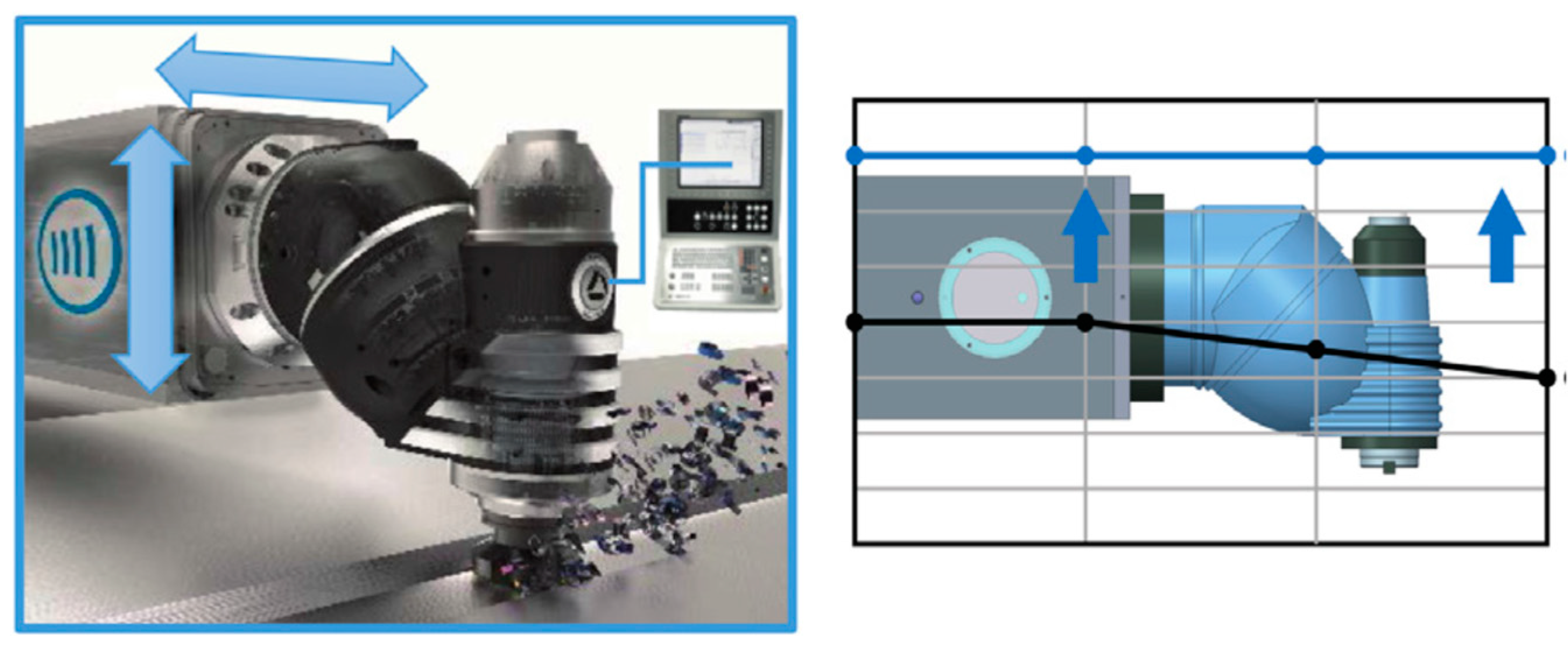
However, the authors of this paper seek to focus mainly on active structural vibration suppression and related actuators, which can be used in particular for vertical rams of large machine tools. The key element in controlled vibration suppression is the solution of the actuator itself. Although it is an essential component of the vibration suppression system, there are relatively few publications that address it (in comparison to those dealing with control). A very comprehensive overview of chatter suppression techniques in metal cutting is provided in papers [8,9]. Nonetheless, these papers do not deal directly with the actuator solutions themselves. However, it provides information on the application of Dynamic Active Stabilizer (DAS®) on a SORALUCE machine (Figure 1). This SORALUCE machine structure, or a very similar structure, is also present in papers [10,11,12]. There are not many similar applications described on other real (commercial) machine tool structures. These machines from SORALUCE are an exception.
The overview of actuators begins with those that work on piezoelectric and magnetostrictive principles. Piezoelectric or other types of actuators are less common for structural vibration suppression. Their use is more common in the domains of vibration suppression of machine spindles, tool holders, workpieces and vibration-assisted machining. A comprehensive overview of devices that are used for vibration-assisted machining is provided in article [13]. Article [14] provides a complex overview of magnetostrictive actuators, including modelling and control issues. Examples of applications of these actuators can be found, for example, in publications [15,16,17,18]. The use of actuators that work on the piezoelectric principle for vibration suppression in two axes is described, for example, in articles [19,20,21]. Although these actuator applications are interesting in this overall overview, none of them directly corresponds to the application of vibration suppression of long, slender and massive structures such as machine tool rams. Generally speaking, actuators suitable for these applications typically work according to the electromagnetic principle.
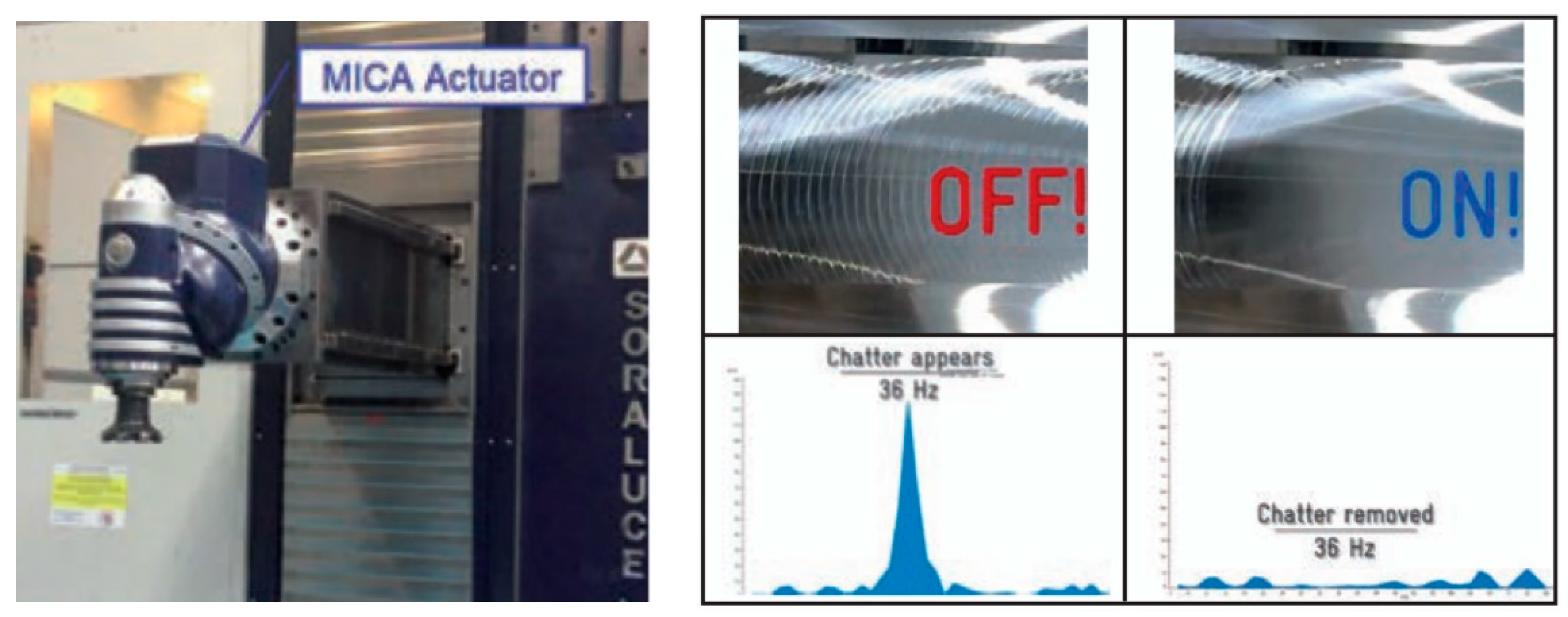
Typical types of electromagnetic actuators include proof-mass actuators (inertial actuators), which are described, for example, in publication [1]. Solutions that combine several pieces of single-axis actuators can be used for cases where a damping force needs to be applied in several directions. An example of the use of single-axis actuators can be found, for example, in paper [22], which presents a technique to suppress chatter in centerless grinding. Two “ADD-2D-1 kN” actuators by Micromega® (Fernelmont, Belgium) were used for this purpose. They combine a linear motor and a voice coil actuator. The same actuators were also used in [23]. An actuator that functions in a similar way was also used in article [10] to suppress the vibrations of the aforementioned SORALUCE machine. In this case, however, the actuator was designed as a biaxial device. Article [10] focuses on control of the actuator rather than on the actuator concept. Another application on a SORALUCE machine is described in article [11], where a MICA® actuator by Cedrat Technologies (Meylan Cedex, France) is used for active damping. In this case study, a resonant frequency of 36 Hz was suppressed, and the surface quality of the machined part was improved (Figure 2).
An interesting concept that employs a two-axial actuator for vibration suppression of boring bars is presented in paper [24] and subsequently used in [25]. These applications describe mounting on a turret of a CNC lathe. Paper [26] describes a planar actuator concept for vibration suppression, which is integrated into the end of the spindle for milling processes. A highly dynamic spindle integrated actuator is also presented in [27]. However, none of these electromagnetic actuators were designed specifically to dampen the vibrations of machine tool rams.
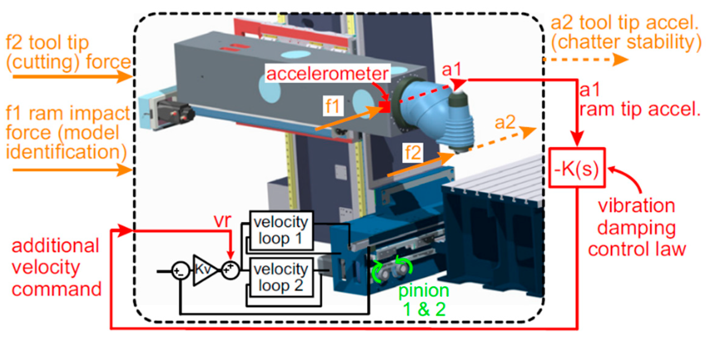
An interesting approach that includes application to the machine is the use of machine drives for vibration suppression (Figure 3). This application is described in article [12] and was also tested on the aforementioned SORALUCE machine. Figure 3 contains a description of a damping vibration method that uses an X-axis feed drive on this horizontal milling machine. A rack and pinion drive is used here, and the compensation signal is entered as an additional velocity command. The control-equipped drive is used to suppress machine oscillations at low frequencies during machining.
This paper aims to supplement the relatively sparse literature on the construction of actuators for vibration suppression of long, slender and massive machine tool structures, especially vertical rams. It presents a conceptual design of a two-axial electromagnetic actuator as well as a description of its construction and basic parts. The main novelty and originality of this solution is that it purposefully uses standard electric drives, which are available in a wide range of parameters. This makes it easier to adapt the actuator parameters to the required application. In terms of influencing the resulting machine accuracy, it is important to monitor the heat losses of the actuator (thermal deformation of the ram). The machine’s thermal influence from the vibration suppression system is not emphasized in any of the cited sources. The concept proposed in this article uses synchronous electric drives (linear motors), which are highly efficient, among other things. The drives used in the case study (hereinafter) allow water cooling to be connected if required. As a result, it is possible to efficiently dissipate heat from a place where it negatively affects machine accuracy. Additionally, it is possible to use higher power levels in motors if necessary and thus achieve higher dynamic forces with actuators. This article also describes the basic concept for controlling the actuator in a current control loop (force control) and demonstration of its function on the ram. This article does not aim to present new control algorithms for vibration suppression. To verify the function of the actuator itself, a simple Direct Velocity Feedback (DVF) control approach is intentionally used here for clarity. The actuator itself works in the current control mode (control of the motor force). It allows the use of virtually any vibration control method. The appropriate control can be chosen with regard to the specific application on the machine.
2. Two-Axial Actuator Conceptual Design
A two-axial actuator is needed to meet the vibration damping requirements of long, slender machine tool parts, such as, in particular, vertical rams on large turning and multifunction machines. Typically, there is a need to increase damping in the proximity of the cutting point. It is often a matter of damping bending oscillations in the two most flexible directions of the ram. The aim is to make the proposed solution scalable in size and power and use drives with standard components. This should make it possible to integrate the solution into machines with different ram solutions.
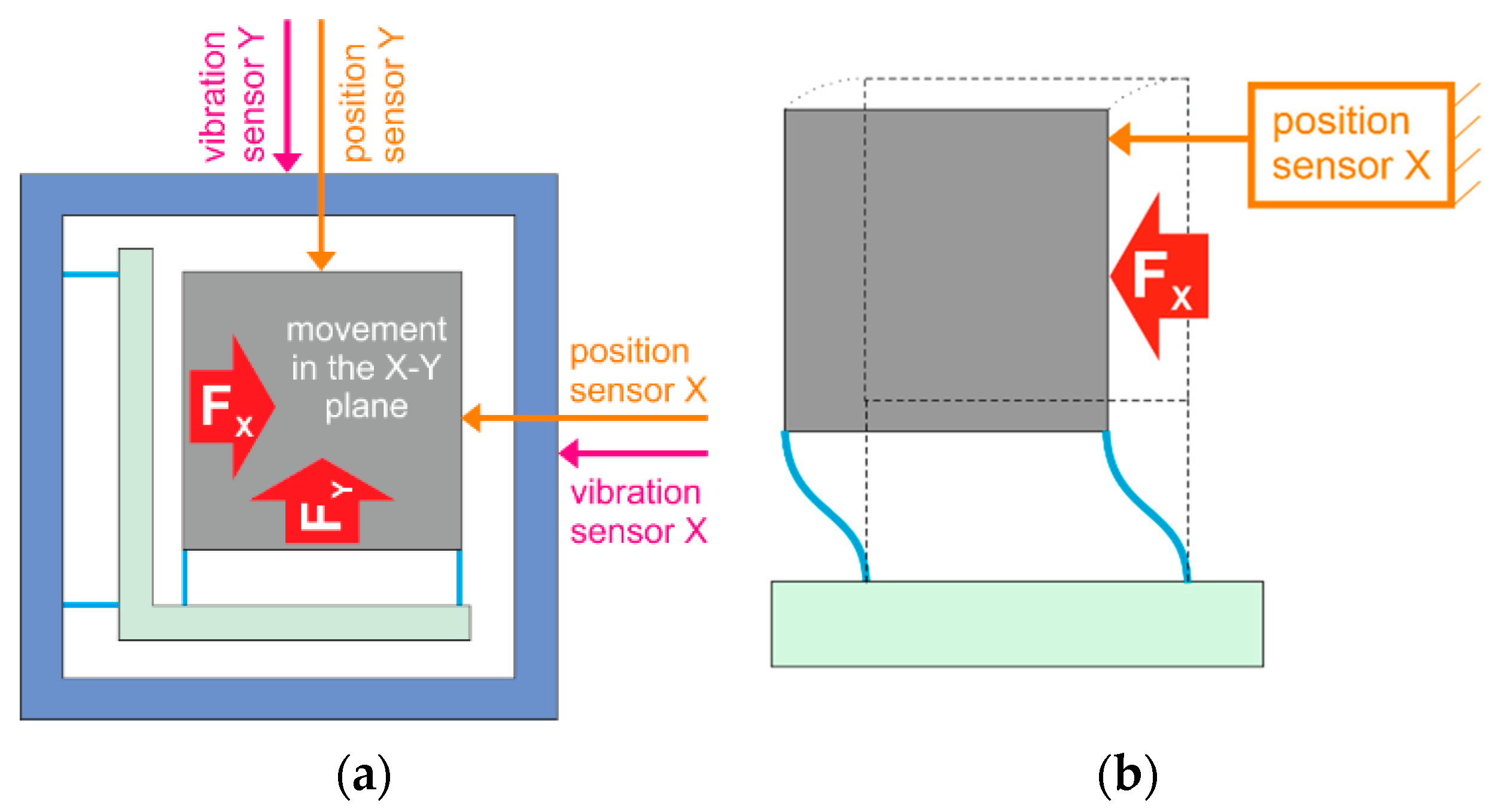
The design of the two-axial actuator builds on previous experience with one-axis actuator design and operation from the authors’ workplace. Conceptually, the design solution is based on the use of an electromagnetic proof mass actuator (voice coil actuator). The aim of designing the two-axial actuator drive is to use standard linear motors and servo inverters. Their specific size and arrangement can be customized for specific applications. In order to eliminate passive resistance and increase the service life of the actuator, the active mass of the actuator is usually mounted with flexures. These must be sufficiently flexible in the direction of the required movement yet sufficiently rigid in other directions. The placement of the active mass of the actuator on the flexures is evident is Figure 4. Actuator drives exert a force on the central part (gray) both in the X direction and in the Y direction (forces Fx and Fy). The movement along the X axis is practically performed only by the central part (gray). The movement along the Y axis is ensured by the central part along with its supporting part (green). Vibration sensors can be located on the outer frame of the actuator (blue) or can be built-in. The disadvantage of using flexures is that there is a small parasitic movement in a direction perpendicular to the desired direction of movement, as indicated in Figure 4a. Although it does not have a significant effect on the resulting actuator parameters, it complicates the selection of the measuring system of the positions of the primary and secondary parts of the motor in relation to each other (Figure 4b).
3. Case Study of the Actuator Design
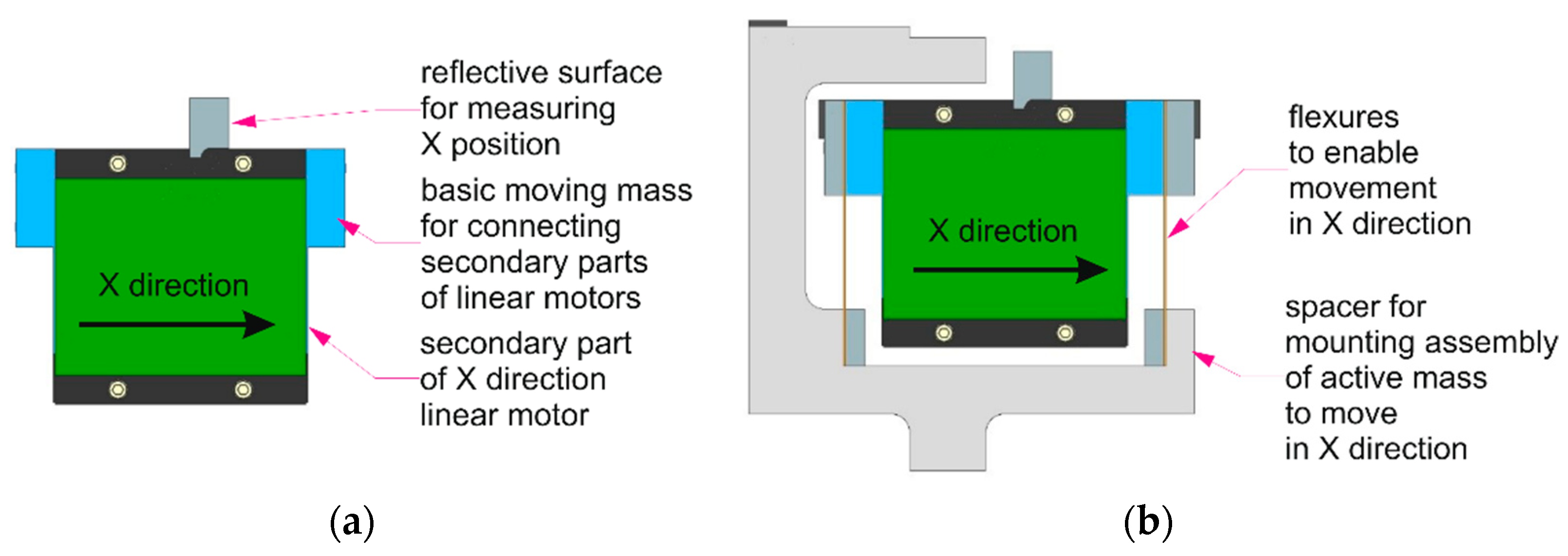
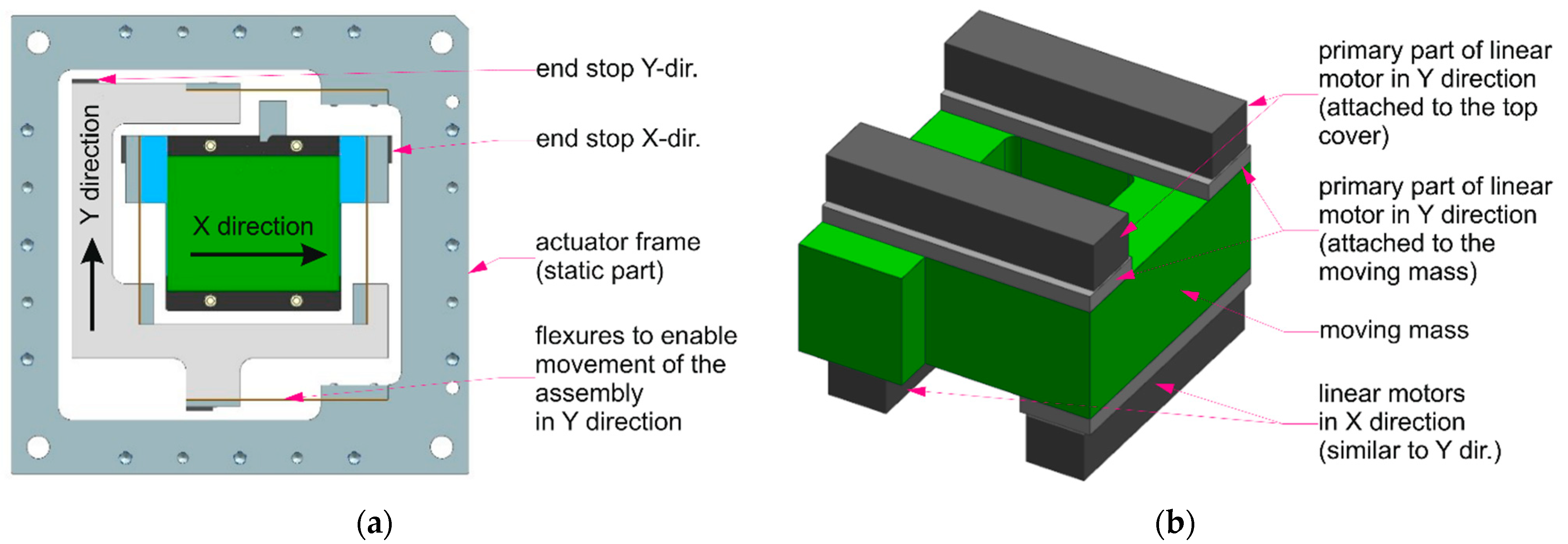
The constructional design solution of the actuator’s central part with a description of its basic components is provided by assembling in Figure 5 and Figure 6a. The basis is a moving mass in the middle section of the actuator (Figure 5a), to which the secondary parts of the linear motors of the X-axis and the Y-axis are mounted perpendicular to each other (a type VUES L3S100S-816 in the case study). In Figure 5a, only drive X is visible. Drive Y is mounted on the other (bottom) side. The mobility of the central part’s mass is ensured by mounting on the flexures against the intermediate piece–the spacer. Together, they form a movable mass along the Y-axis (Figure 5b). This spacer is further mounted on the flexures against the actuator’s base frame (Figure 6a). Mobility along both axes is limited by rubber end stops. The central part of the actuator can also be designed as a version with a through center (Figure 6b).
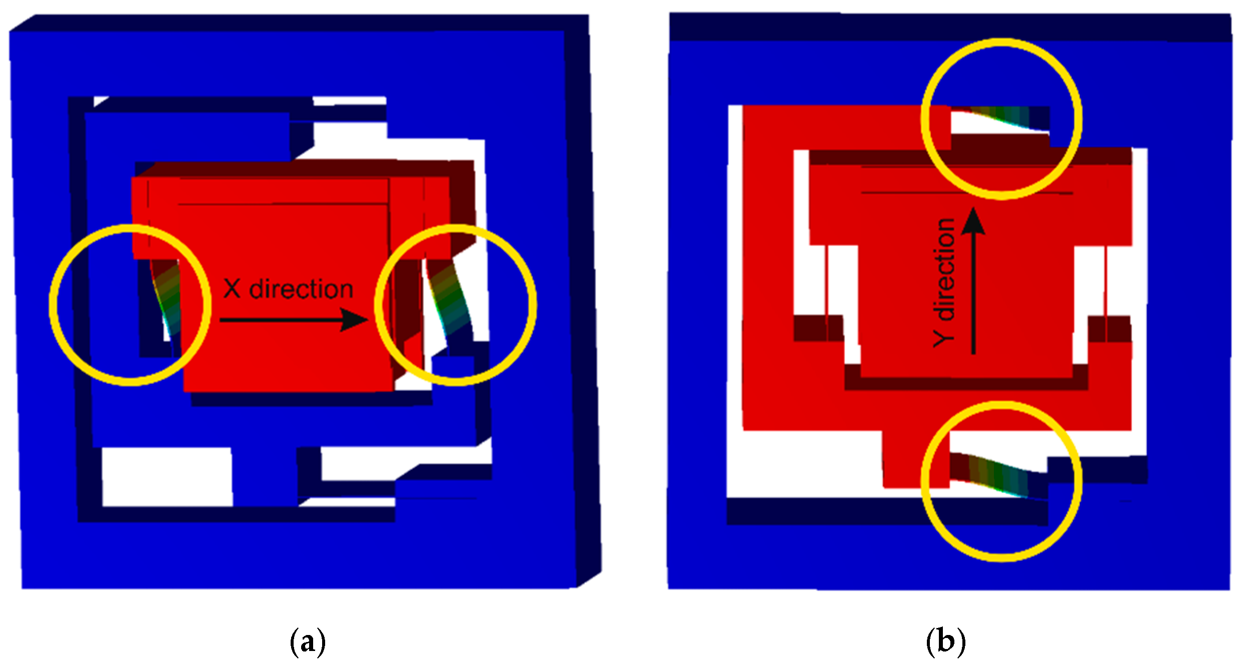
During the design process, significant attention was paid to the suspension of active mass on the flexures. The design (case study) was performed for specific linear motors with a continuous traction force of 440 N (see description below). The suspension was optimized using the parametric FEM model. Traction forces from the linear motors in the X and Y directions enter the model as loads. The gravitational force and attractive forces from permanent magnets between the primary and secondary parts of the linear motors then act perpendicular to them (Z direction). The aim of the optimization was to achieve low natural frequencies of the active body suspension in the flexible direction while requiring high rigidity in other directions to prevent the flexures from collapsing at the limit loads (loss of stability). This would cause contact between the primary and secondary parts of one of the motors, which could lead to damage to the actuator in extreme cases. In this case study, a value of 0.2 mm was chosen as a safe design value of maximum deformation in the Z direction. The aim was to choose the flexure parameters so that the lowest natural frequencies are approx. around 15 Hz. An example of the calculated first eigenshapes with flexures that meet the selected conditions is shown in Figure 7a,b. Another condition was that the stress in any part of the flexures must not exceed the safe level for the given material (spring steel EN 1CS67) at maximum deformation. The calculations also included topological optimization of the flexure shape, which aimed to minimize the natural frequency of the suspension while maintaining the maximum rigidity in the Z direction and minimum stress in the flexures. However, the benefits of such optimization were not unambiguous, and thus, finally, simple rectangular flexures were chosen. The flexure (plate) thickness parameter was chosen from available metallurgical products.
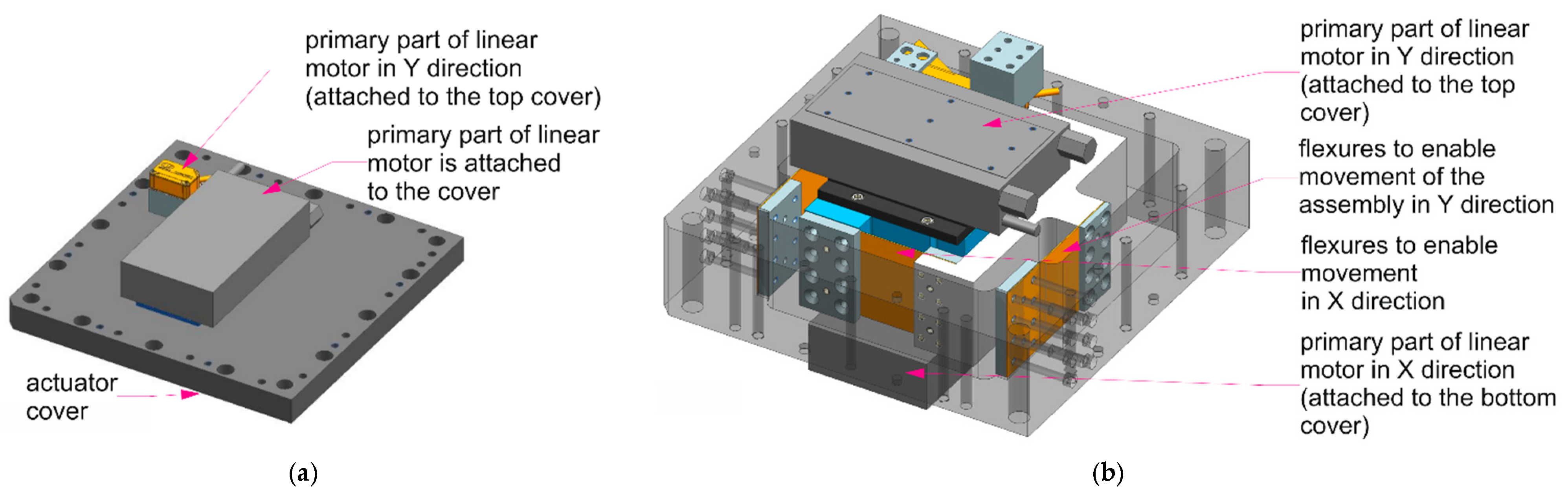
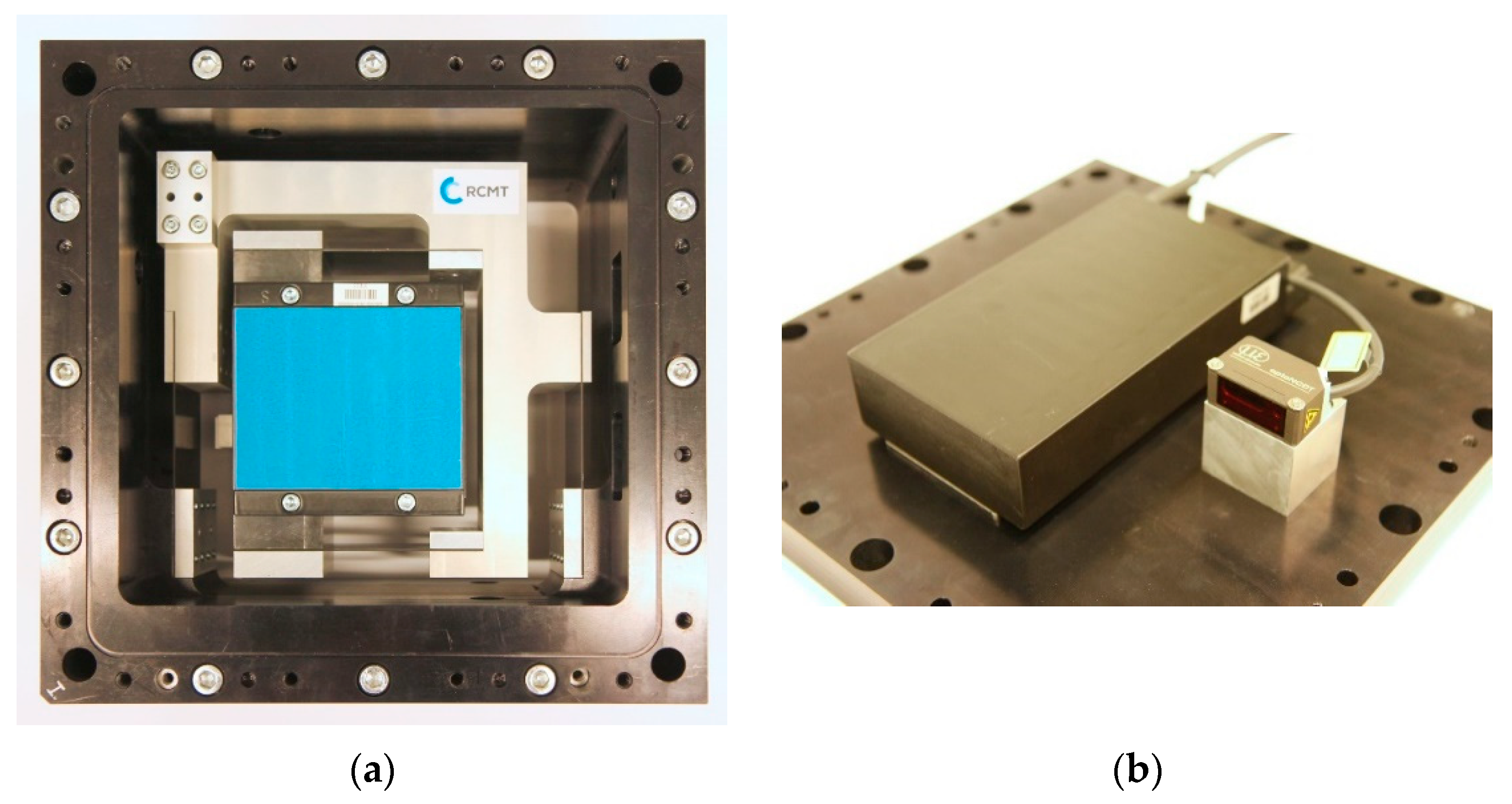
The central part of the actuator contains only the secondary parts of the linear motors with permanent magnets. The primary parts of the motor (water-cooled type VUES L3SK075P-1215) are attached to the actuator covers along with an absolute non-contact position sensor (Micro-Epsilon ILD1320-50). The actuator cover assembly is shown in Figure 8a. In Figure 8b, there is a 3D view of the actuator center assembly along with the location of the primary parts of the linear motors (for clarity).
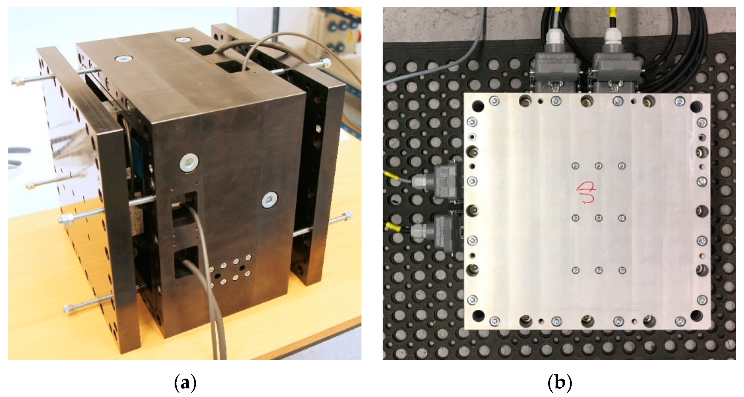
Figure 9a provides a view of the mounted assembly central part of the actuator. Figure 9b shows the mounted assembly of one of the covers. Due to the large attractive forces between the primary and secondary parts of the linear motors, the installation of the covers on the central part must occur simultaneously from both sides while both covers are gradually closed using the push-off screws (Figure 10a). The assembled actuator is supplemented with industrial connectors to enable better cabling connection options (Figure 10b).
The specific actuator (case study) was designed to enable testing on a test ram of real dimensions. The external dimensions of the actuator are 340 × 340 × 270 mm3 (X, Y, Z), the total weight of one complete actuator is 80 kg, and the intended operating frequency range of the actuator is from 20 to 300 Hz. The basic parameters for the X and Y axes of the designed actuator are summarized in Table 1. For the purposes of testing on a model ram, two structurally identical actuators were manufactured (see below). The actuator drives are designed to allow the connection of water cooling. This corresponds (in theory) to a higher continuous achievable traction force. However, water cooling is considered mainly due to the reduction of the actuator’s thermal effect on the machine ram.
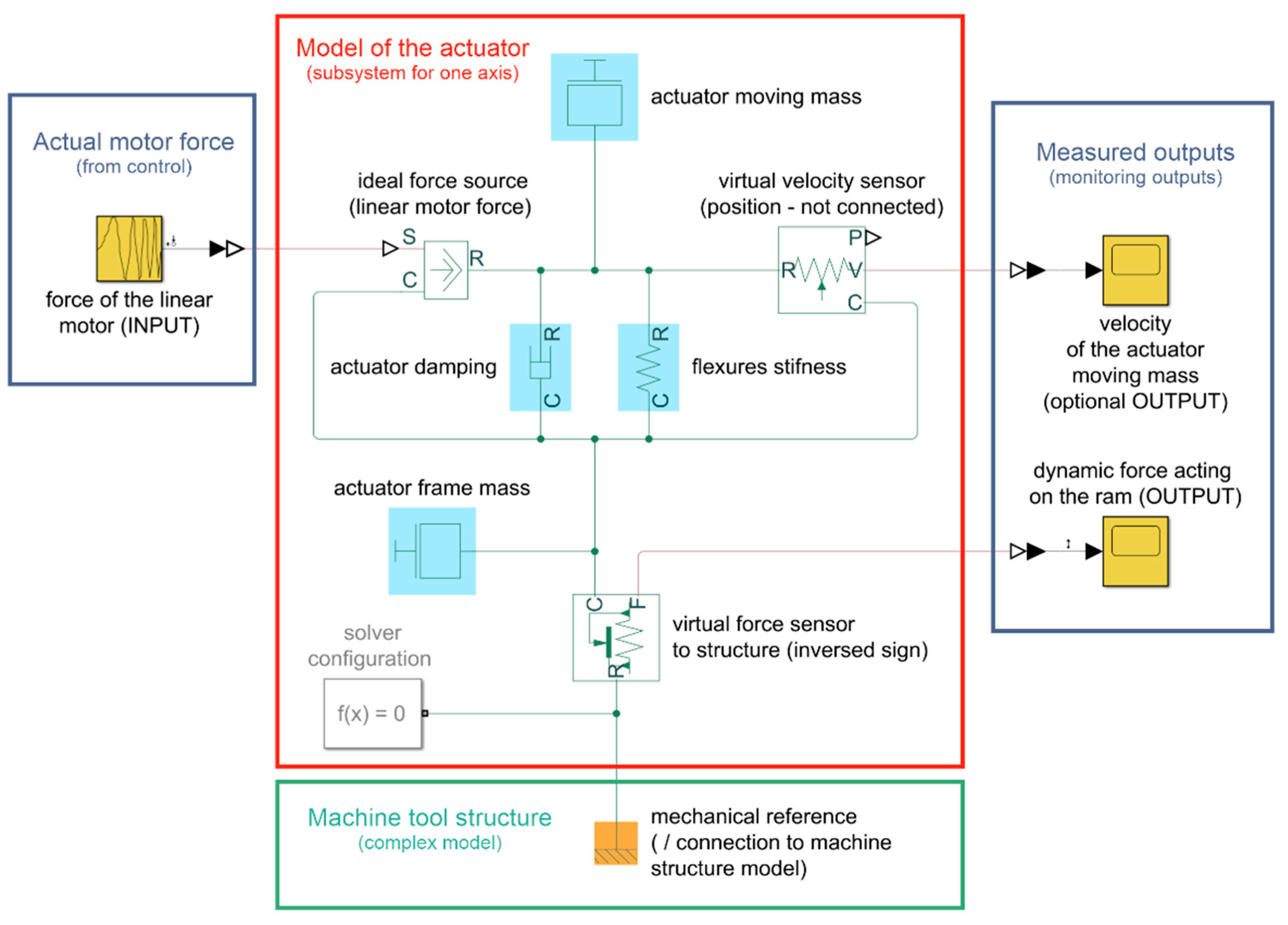
The mathematical model of the actuator can be relatively simply described analytically (e.g., in [1]). However, for the sake of clarity, this article shows a model created in the Matlab Simscape environment. This model is presented in Figure 11 and can be understood as a subsystem that will have the same structure for both the X-axis and the Y-axis. The values in the actuator model can be substituted according to Table 1. The actuator subsystem created in this way can be connected both to a complex model of the entire machine structure (e.g., in state-space form-reduced FEM model) and to a vibration control model. To close the control loop, this model would be supplemented by a virtual acceleration sensor, which would be placed on the “actuator frame mass” element or on a suitable element of the machine tool structure model (in close proximity to the actuator). This paper does not deal directly with control algorithms for vibration dampers. A simple controller, a Direct Velocity Feedback (DVF) as described in [1], is intended to be used to verify the actuator’s function as a damper. The force entering the actuator model in Figure 11 is obtained from the controller by multiplying the value of the motor current and the motor force constant.
In practice, the motor’s force constant may differ slightly from the catalogue value. The biggest differences may be related to motor overload and warm-up. However, machine tool ram warming is a significant potential source of machine inaccuracy. The actuator for the vibration damper is intentionally designed with motors that allow water cooling. The primary purpose is not to achieve a higher force but a lower thermal effect. The operation of the actuator is realistically assumed to be at maximum continuous catalogue values, which are permissible for the motor without cooling. Under these conditions, the motor’s force constant can be considered approximately as a constant, which provides a conversion between the motor’s current and action force with sufficient accuracy (for a given purpose).
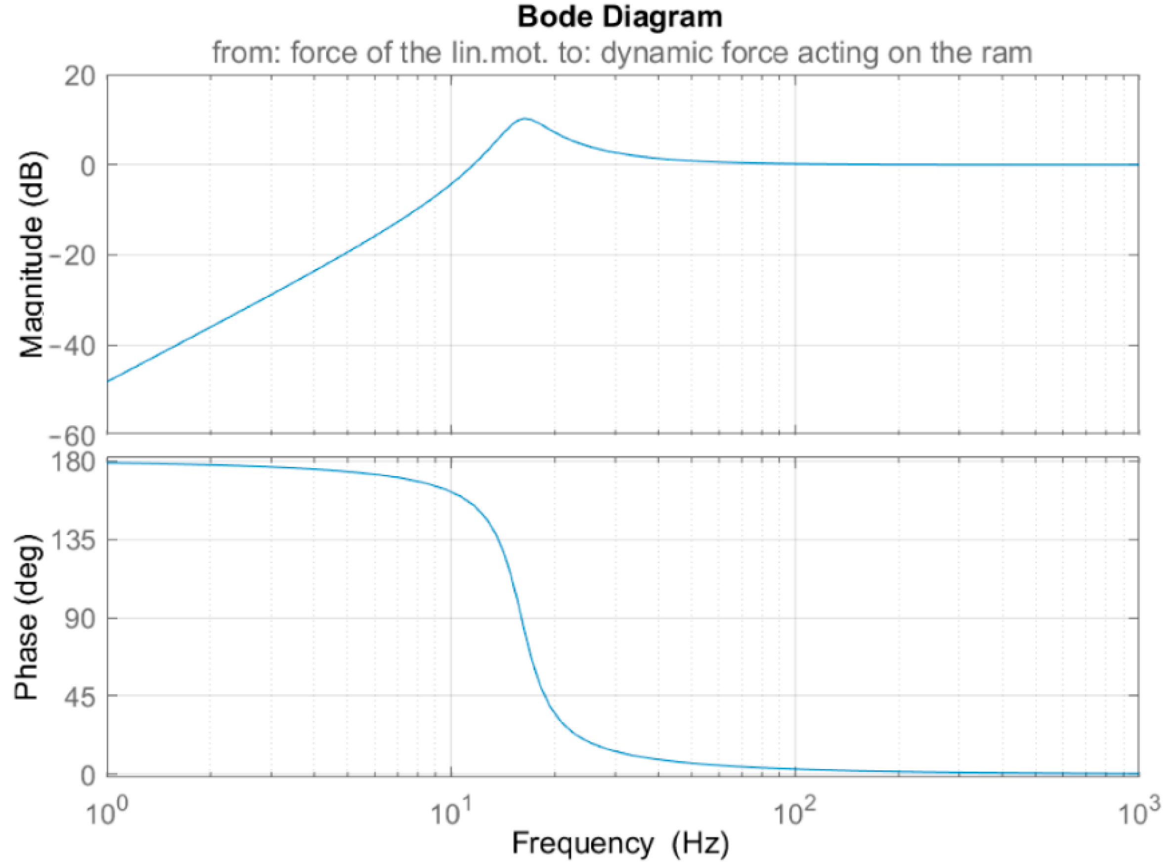
The actuator model in Figure 11 has a transfer function, which is plotted in Figure 12 after the substitution of the X-axis parameters from Table 1 (for illustration). For low frequencies, the transmission of force to the machine structure is small. It grows around the resonance of the actuator (16 Hz), and subsequently, the transmission amplitude stabilizes at value 1 (0 dB). The value of the phase shift is practically negligible for higher frequencies. The actuator then acts as a good source of force. For the case study application in this article, the main focus is on vibration suppression around 70 Hz (see text below). In this area, the actuator already works with minimal distortion. For this reason, no special attention needs to be paid to force compensation according to the transfer function in Figure 12 during the experiments described below.
The great advantage of the proposed actuator design is the ability to measure the absolute position of the actuator moving mass (laser sensor, Figure 8a). The model’s stiffness parameters can be verified (in this case) by measuring static deformation at a specific linear motor force. In the normal vibration suppression mode, the flexure deformations are usually relatively small and can be considered linear. The damping coefficient can be approximately estimated using the position response to the force step demand.
4. Solving the Problem of Actuator Control in the Current Control Loop
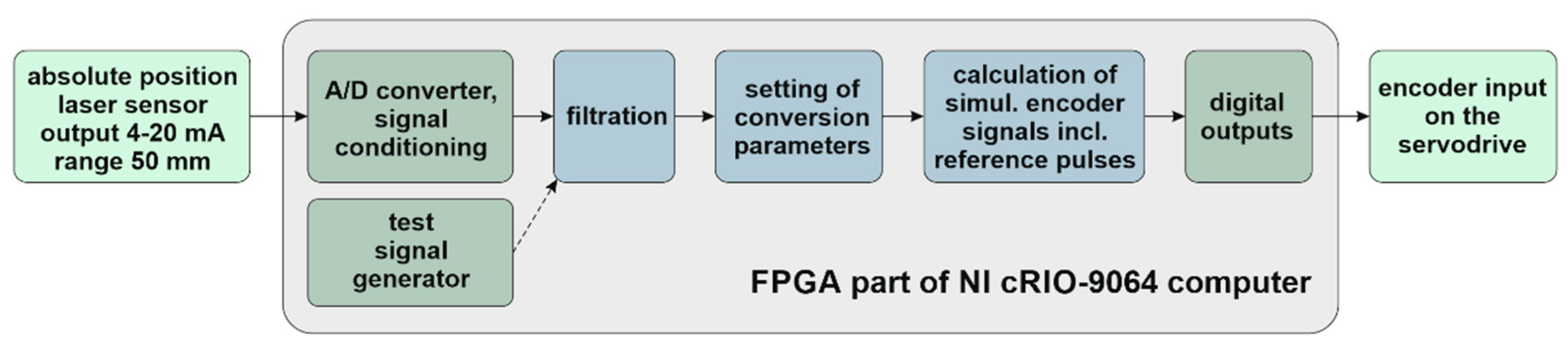
In order for linear motors to function properly, it is necessary to ensure the measurement of the positions of the motor’s primary and secondary parts in relation to each other (commutation of linear motors). Due to the parasitic movement of the mass on the flexures mentioned above, this is relatively problematic to ensure. Standard position sensors for linear motors (optical sensors and other types) are able to tolerate this movement only to a very small extent, which is not enough in practical terms. Hall sensors are an exception, but they cannot be used for common components in this case due to the installation dimensions. For these reasons, an absolute laser noncontact position sensor with a range of 50 mm (specifically a Micro-Epsilon ILD1320-50) was used to measure the position of the active mass. At the time of writing this paper, the sensors available on the market do not have an output that can be fed as a feedback signal to the servo inverter. The sensor selected for this case study has a current output of 4–20 mA, which must be converted to another type of signal that is compatible with commonly available drives. The most universal signal is likely the TTL signal from incremental position sensors, which is supported by virtually all servo inverter manufacturers. However, no signal converter with the required parameters is available on the market. For this reason, a custom converter was designed on the FPGA part of the NI cRIO-9064 computer. The block diagram of the converter for one channel is shown in Figure 13. The output is a standard incremental encoder signal in the RS422 standard (TTL) with an adjustable length period (position increment) and a reference mark. This solution allows the actuator drives to be commutated after start-up and further operated in standard mode in the current control loop (which corresponds practically to force control).
The authors of this paper also have experience with other applications where the RS422 encoder was used in the vibrating system. Due to the higher vibration frequencies and higher resolution of the encoder, there was an occasional loss of pulse reading. This problem was prevented here by the fact that the sensor (laser) works as an absolute. A possible loss of pulses when reading the simulated encoder signal would be quickly corrected by using a reference pulse, which is generated in the middle stroke position. During testing, this signal conversion system proved to be sufficiently robust. No commutation problem or encoder error was detected on the servo inverter.
5. Experimental Verification of Actuator Function
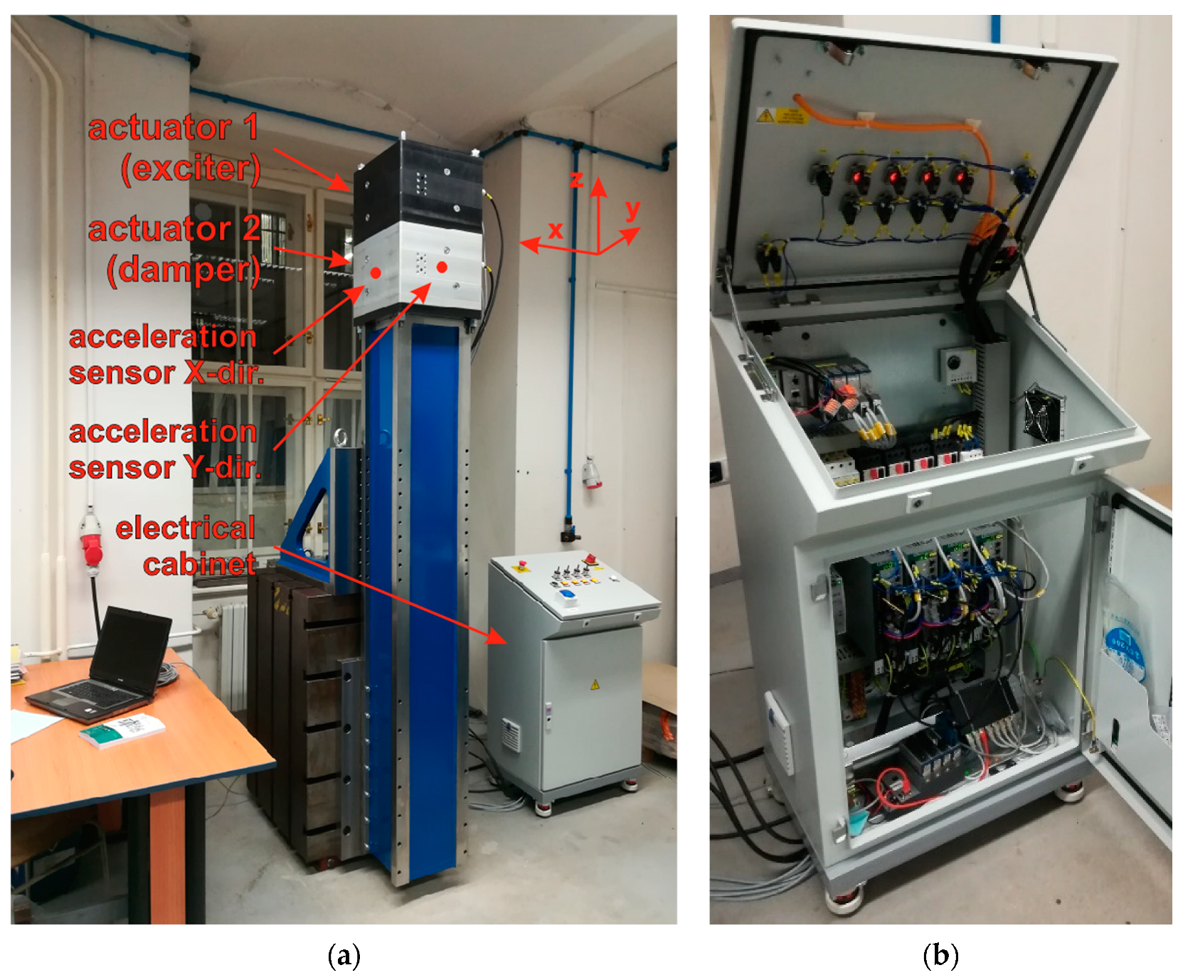
A test ram measuring 270 × 270 × 2000 mm3 was used to verify the actuator function. The ram was attached to a cast-iron cube in an inverse vertical position and then fixed to the floor. Both manufactured actuators were attached to the upper clamping plate of the ram. The arrangement of the measurements is visible in Figure 14a. A view of the electrical cabinet for the actuator drives is shown in Figure 14b.
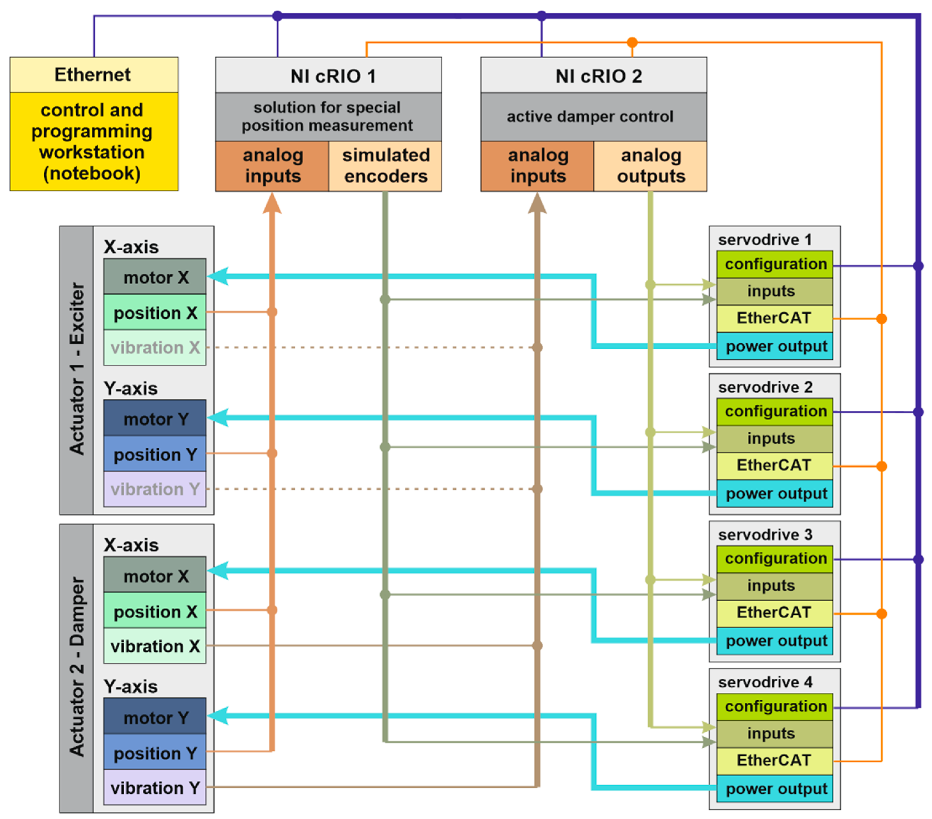
The actuator control block diagram in Figure 15 consists of two parts. The first part involves measuring, i.e., the solution of the aforementioned simulated signal of the incremental encoder. The second part concerns the input of the current setpoint signal for each of the four controlled linear motors. Conventional servo amplifiers (Kollmorgen AKD-P00607-NBCC, Radford, VA, USA) were used for control. The setpoint can be entered into the selected drives either in digital form via the EtherCAT bus or using the analog voltage input of the inverter. Although analog input can be problematic because it is more susceptible to electrical noise, it nonetheless seems to be more suitable for vibration suppression applications because it has less transport delay. This is also the case selected in Figure 15.
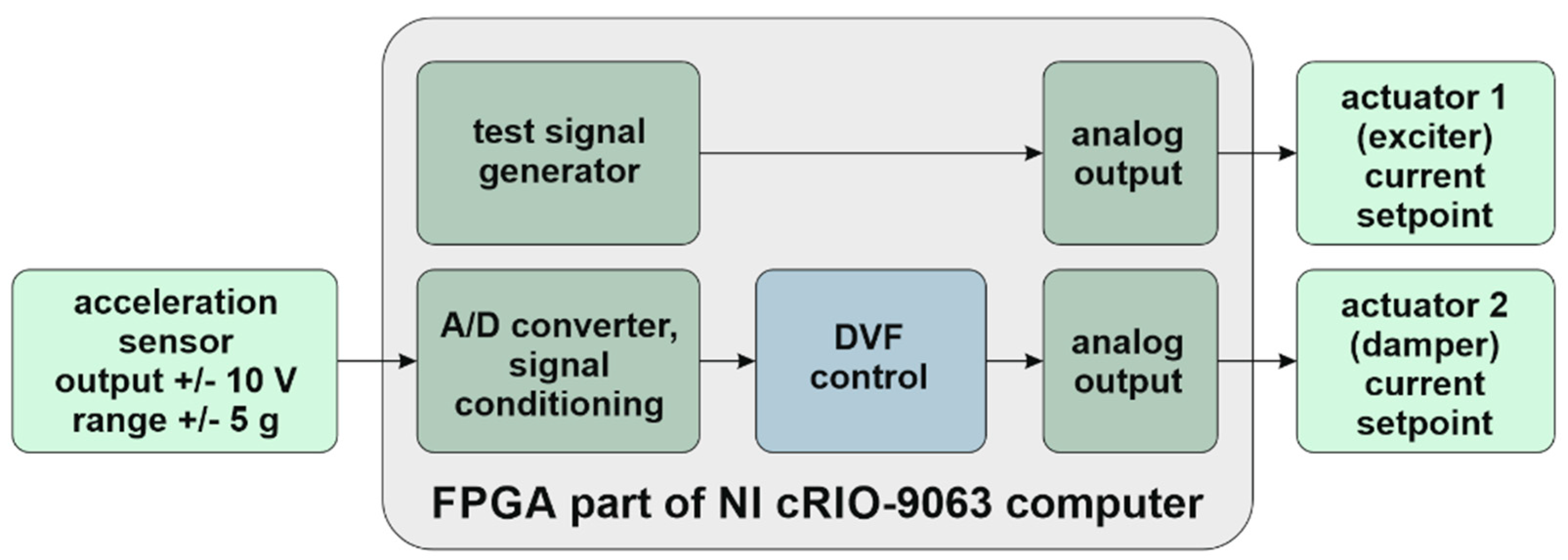
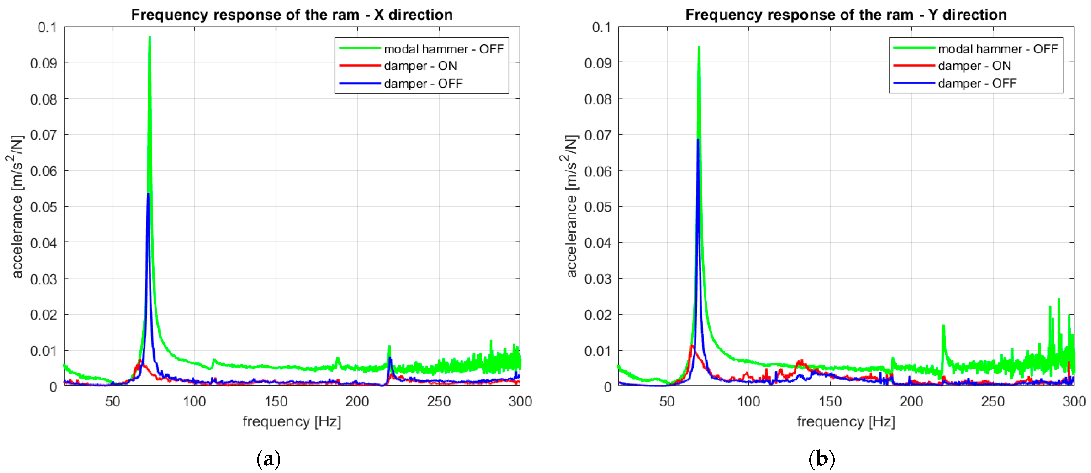
This paper does not deal directly with control algorithms for vibration dampers. A simple controller, a Direct Velocity Feedback (DVF) as described in [1], was used to verify the function of the actuators as dampers. The integration of signals from accelerometers (Kistler PiezoBeam 8640A5T, Winterthur, Switzerland) was used to close the feedback. The control loop and test signal generation were implemented on a NI cRIO-9063 computer (Figure 16). The algorithm was the same for both directions, and the control cycle frequency was 20 kHz. The control of actuator 1 (exciter) and control of actuator 2 (damper) run on the same computer but completely independently of each other. The gain of the vibration damper controllers (DVF) was experimentally adjusted so that the amplitude decreased at the monitored frequencies in the region around 70 Hz (Figure 17). At the same time, it was important to maintain the stability of the regulation and not cause a significant spillover effect on the surrounding frequencies.
As a reference measurement, a classical measurement of the amplitude frequency transfer function of the ram was taken (Figure 17—green lines). The excitation was carried out using a modal hammer (PCB 086D05, PCB Piezotronics, Depew, NY, USA) at the location of the accelerometers on actuator 2. A separate acceleration sensor (Kistler K-Shear 8702B50M1, Winterthur, Switzerland) was used to measure the response. This sensor was placed in close proximity to the accelerometers for active control feedback. The actuators were switched off while this measurement was taken. Further measurements were taken with the amplitude frequency response excitation progressively point by point using actuator 1 as an exciter in the given frequency range (20–300 Hz). The actuator at the end of the ram was chosen for excitation, as this corresponds to the real cutting force position. A frequency step of 0.2 Hz was selected for the measurement. The conversion of excitation to force was performed using the force constant of the linear motors (120 N/A for the given motors). The amplitude of the excitation force during the measurement was, after recalculation, approximately 70 N in the entire frequency range, which corresponds to approximately 15% of the actuator’s nominal value. This value was chosen as the safe limit for overcoming the resonance range around 70 Hz (excitation by the actuator nominal value was only possible in the safe area outside the resonance).
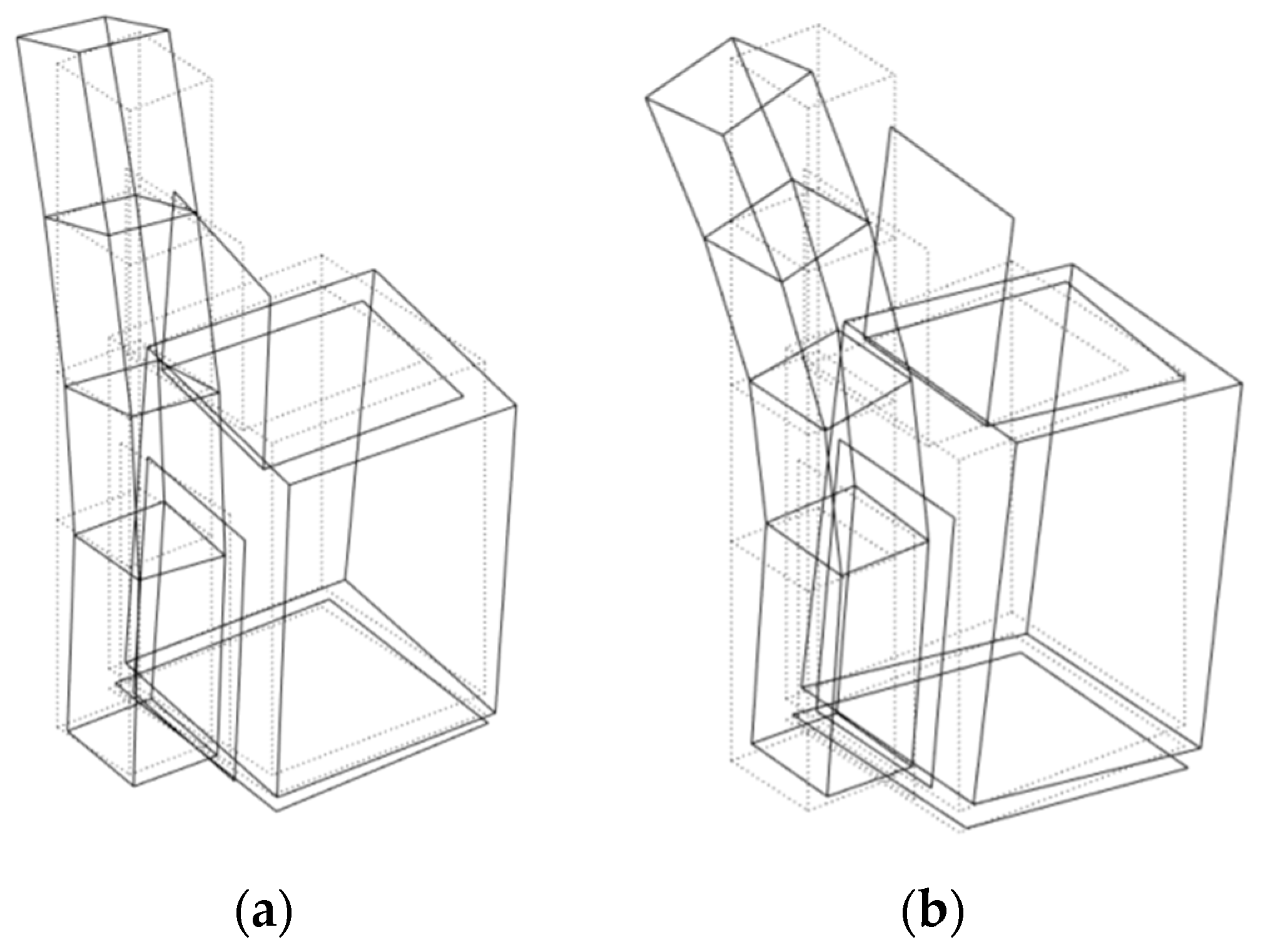
One measurement was performed with actuator 2 switched off (Figure 17—blue lines). During the second measurement, the vibration damper-actuator 2 with the Direct Velocity Feedback (DVF) control was switched on (Figure 17—red lines). In the X-axis of the ram, there is only one dominant bending natural frequency in the given frequency range at the value of 72 Hz (eigenshape in Figure 18a). In the Y-axis it is 70 Hz (the eigenshape in Figure 18b). Furthermore, frequencies corresponding to torsional modes predominate. These cannot be significantly affected by the damper. With the use of a damper, it was possible to reduce the amplitude of the most important bending mode to approximately 15% of the original value in both directions.
The frequency transfer function graphs show the differences between the measurement excited by a modal hammer and point by point by actuator 1. These differences are attributed to the error that is introduced into the measurement by converting the excitation force from the actuator current through the catalogue value of the force constant. The conversion of the force transmission to the ram (according to the Bode diagram in Figure 12) in this presented frequency range has no significant effect. A completely different level of excitation force also plays an important role. When excited by the actuator, the measurement occurs at large excitation amplitudes, and vibrations stabilize at individual frequencies. For these reasons, the differences in the measured transmissions are understandable, and the agreement can be considered acceptable. This is especially true for the 70 Hz region, where the most significant bending modes are located.
6. Conclusions
This paper describes a two-axial actuator concept for vibration dampers, which is designed specifically for damping bending modes of vertical rams of large turning and multifunctional machine tools. In the introductory section of the paper, an overview of relevant actuators for vibration suppression was presented. The field of research was expanded to include relevant actuators for vibration-assisted machining.
The actuator presented in this article was designed as an intermediate piece (spacer) between the end of the ram and the tool head. The main novelty and originality of the presented solution are that it purposefully uses standard electric drives, which are available in a wide range of parameters. This makes it easier to adapt the actuator parameters to the required application. In terms of influencing the resulting machine accuracy, it is also very important to monitor the heat losses of the actuator (thermal deformation of the ram). The concept proposed in this article uses synchronous electric drives (linear motors), which excel, among other things, in high efficiency. The drives used in the case study allow the connection of water cooling if required. It is thus possible to efficiently dissipate heat from a place where it negatively affects the accuracy of the machine. At the same time, it is theoretically possible to use higher power of motors if necessary and thus achieve higher dynamic forces with the same actuator. If a pair of linear motors are used for each direction, it is possible to keep the actuator center free (e.g., for spindle drive shafts). This option is also not common for other actuators found in the cited references.
The article presents a case study of the specific actuator for a nominal continuous force of 440 N and a range of operating frequencies from 20 to 300 Hz. It also summarizes the basic parameters of the assembled device and a model that will allow the simulation of the actuator with the given parameters within a complex model of the machine. From the presented model, it is possible to approximately determine the actuator’s basic dynamic characteristic between the force exerted by the linear motor and the force transmitted through the elastic suspension (flexures) to the structure of the machine tool.
The paper also addresses the concept of noncontact measurement of the moving mass of the actuator, guided on the flexures. Information on the position of the moving mass can be used for the commutation of linear motors and, if necessary, for the control of the vibration damper itself.
The actuator was installed on a real-size test ram, and its function as a vibration damper was verified. This article does not aim to present any new control algorithms for vibration suppression. To verify the function of the actuator, a simple Direct Velocity Feedback (DVF) control approach is intentionally used here for clarity. The actuator itself works in the current control mode (controlling the motor force). It allows the use of virtually any method of vibration control. The appropriate control can be chosen with regard to the specific application on the machine.
In the presented case study, two NI cRIO computers were used to control the complete application. One of the computers solved the functions of special position measurement, while the other ran the control of the actuators. In a practical application on a machine tool, only one two-axial actuator would be used, and only one NI cRIO control computer would suffice. The number of inputs and outputs of one computer, as well as the computing power, would be sufficient to control a complete application. Communication between the NI cRIO and the machine tool control system may not be in real-time (at high rates). It may thus proceed via standard communication protocols. The presented solution is applicable in practice and can be integrated into existing industrial control systems. Applications can be mainly expected in the field of vibration suppression of vertical rams of large machine tools.
Author Contributions
L.N.: conceptualization, data curation, formal analysis, methodology, supervision, validation, visualization and writing—original draft; J.Č.: conceptualization, data curation, visualization and writing—original draft; M.S.: formal analysis, funding acquisition, project administration and supervision; J.Š.: project administration and validation; M.J.: data curation and visualization; P.K.: project administration and resources. All authors have read and agreed to the published version of the manuscript.
Funding
Funding support from the Czech Ministry of Education, Youth and Sports under the project CZ.02.1.01/0.0/0.0/16_026/0008404 “Machine Tools and Precision Engineering” financed by the OP RDE (ERDF). The project is also co-financed by the European Union.
Institutional Review Board Statement
Not applicable.
Informed Consent Statement
Not applicable.
Data Availability Statement
Not applicable.
Conflicts of Interest
The authors declare no conflict of interest.
References
- Preumont, A. Vibration Control of Active Structures: An Introduction; Springer: Dordrech, The Netherlands, 2011; ISBN 9789400720336. [Google Scholar]
- Fuller, C.; Elliott, C.S.; Nelson, P.A. Active Control of Vibration; Academic Press: Cambridge, MA, USA, 1996; ISBN 9780080525914. [Google Scholar]
- Hansen, C.H. Active Control of Noise and Vibration; CRC Press: Boca Raton, FL, USA, 2013; ISBN 9781466563360. [Google Scholar]
- Elvin, N.; Erturk, A. Advances in Energy Harvesting Methods; Springer: New York, NY, USA, 2013; ISBN 9781461457053. [Google Scholar]
- Kaźmierski, T.J.; Beeby, S. Energy Harvesting Systems: Principles, Modeling and Applications; Springer: New York, NY, USA, 2010; ISBN 9781441975669. [Google Scholar]
- Zaeh, M.F.; Kleinwort, R.; Fagerer, P.; Altintas, Y. Automatic tuning of active vibration control systems using inertial actuators. CIRP Ann. 2017, 66, 365–368. [Google Scholar] [CrossRef]
- Kleinwort, R.; Platz, J.; Zaeh, M.F. Adaptive active vibration control for machine tools with highly position-dependent dynamics. Int. J. Autom. Technol. 2018, 12, 631–641. [Google Scholar] [CrossRef]
- Munoa, J.; Beudaert, X.; Dombovari, Z.; Altintas, Y.; Budak, E.; Brecher, C.; Stepan, G. Chatter suppression techniques in metal cutting. CIRP Ann. 2016, 65, 785–808. [Google Scholar] [CrossRef]
- Yue, C.; Gao, H.; Liu, X.; Liang, S.Y.; Wang, L. A review of chatter vibration research in milling. Chin. J. Aeronaut. 2019, 32, 215–242. [Google Scholar] [CrossRef]
- Munoa, J.; Mancisidor, I.; Loix, N.; Uriarte, L.G.; Barcena, R.; Zatarain, M. Chatter suppression in ram type travelling column milling machines using a biaxial inertial actuator. CIRP Ann. 2013, 62, 407–410. [Google Scholar] [CrossRef]
- Meneroud, P.; Porchez, T.; Muñoa, J.; Rowe, S.; Pages, A.; Benoit, C.; Belly, C. Moving Iron Controllable Actuator: Performances in Closed Loop. Proc. Actuator 2014, 14, 530–533. [Google Scholar]
- Munoa, J.; Beudaert, X.; Erkorkmaz, K.; Iglesias, A.; Barrios, A.; Zatarain, M. Active suppression of structural chatter vibrations using machine drives and accelerometers. CIRP Ann. 2015, 64, 385–888. [Google Scholar] [CrossRef]
- Zheng, L.; Chen, W.; Huo, D. Review of vibration devices for vibration-assisted machining. Int. J. Adv. Manuf. Technol. 2020, 108, 1631–1651. [Google Scholar] [CrossRef]
- Apicella, V.; Clemente, C.S.; Davino, D.; Leone, D.; Visone, C. Review of Modeling and Control of Magnetostrictive Actuators. Actuators 2019, 8, 45. [Google Scholar] [CrossRef] [Green Version]
- Zheng, L.; Chen, W.; Huo, D.; Lyu, X. Design, Analysis, and Control of a Two-Dimensional Vibration Device for Vibration-Assisted Micromilling. IEEE/ASME Trans. Mechatron. 2020, 25, 1510–1518. [Google Scholar] [CrossRef]
- Lu, M.; Zhao, D.; Lin, J.; Zhou, X.; Zhou, J.; Chen, B.; Wang, H. Design and analysis of a novel piezoelectrically actuated vibration assisted rotation cutting system. Smart Mater. Struct. 2018, 27, 095020. [Google Scholar] [CrossRef]
- Titsch, C.; Li, Q.; Kimme, S.; Drossel, W.-G. Proof of Principle of a Rotating Actuator Based on Magnetostrictive Material with Simultaneous Vibration Amplitude. Actuators 2020, 9, 81. [Google Scholar] [CrossRef]
- Wang, G.; Zhou, X.; Ma, P.; Wang, R.; Meng, G.; Yang, X. A novel vibration assisted polishing device based on the flexural mechanism driven by the piezoelectric actuators. AIP Adv. 2018, 8, 015012. [Google Scholar] [CrossRef]
- Tůma, J.; Šimek, J.; Mahdal, M.; Pawlenka, M.; Wagnerova, R. Piezoelectric actuators in the active vibration control system of journal bearings. J. Phys. Conf. Ser. 2017, 870, 012017. [Google Scholar] [CrossRef]
- Pugi, L.; Abati, A. Design optimization of a planar piezo-electric actuation stage for vibration control of rotating machinery. Meccanica 2020, 55, 581–596. [Google Scholar] [CrossRef]
- Sallese, L.; Grossi, N.; Scippa, A.; Campatelli, G. Numerical investigation of chatter suppression in milling using active fixtures in open-loop control. J. Vib. Control. 2018, 24, 1757–1773. [Google Scholar] [CrossRef]
- Barrenetxea, D.; Mancisidor, I.; Beudaert, X.; Munoa, J. Increased productivity in centerless grinding using inertial active dampers. CIRP Ann. 2018, 67, 337–340. [Google Scholar] [CrossRef]
- Peukert, C.; Pöhlmann, P.; Merx, M.; Müller, J.; Ihlenfeldt, S. Modal-Space Control of a Linear Motor-Driven Gantry System. MM Sci. J. 2019, 12, 3285–3292. [Google Scholar] [CrossRef]
- Lu, X.; Chen, F.; Altintas, Y. Magnetic actuator for active damping of boring bars. CIRP Ann. 2014, 63, 369–372. [Google Scholar] [CrossRef]
- Chen, F.; Liu, G. Active damping of machine tool vibrations and cutting force measurement with a magnetic actuator. Int. J. Adv. Manuf. Technol. 2017, 89, 691–700. [Google Scholar] [CrossRef]
- Wan, S.; Li, X.; Su, W.; Yuan, J.; Hong, J.; Jin, X. Active damping of milling chatter vibration via a novel spindle system with an integrated electromagnetic actuator. Precis. Eng. 2019, 57, 203–210. [Google Scholar] [CrossRef]
- Königsberg, J.; Reiners, J.; Ponick, B.; Denkena, B.; Bergmann, B. Highly dynamic spindle integrated magnet actuators for chatter reduction. Int. J. Autom. Technol. 2018, 12, 669–677. [Google Scholar] [CrossRef]
Figure 1.
Dynamic Active Stabilizer (DAS®) by SOLARUCE [8]. Reprinted with permission from ref. [8]. Copyright 2016 Elsevier.

Figure 2.
MICA® actuator on a SOLARUCE machine [11].
Figure 2.
MICA® actuator on a SOLARUCE machine [11].

Figure 3.
Active vibration suppression using machine drives [12]. Reprinted with permission from ref. [12]. Copyright 2015 Elsevier.

Figure 4.
(a) A schematic of the proposed 2-axial actuator. (b) The mass guided by the flexures performs a small parasitic movement.
Figure 4.
(a) A schematic of the proposed 2-axial actuator. (b) The mass guided by the flexures performs a small parasitic movement.

Figure 5.
(a) The active mass in the X direction; the secondary part of motor Y is located on the opposite part of the body, perpendicular to direction X; (b) The active mass in the Y direction.
Figure 5.
(a) The active mass in the X direction; the secondary part of motor Y is located on the opposite part of the body, perpendicular to direction X; (b) The active mass in the Y direction.

Figure 6.
(a) The suspension of active mass with secondary parts of the motor in the Y direction (mounted on the other side); (b) An example of the design solution of the central body with a through hole.
Figure 6.
(a) The suspension of active mass with secondary parts of the motor in the Y direction (mounted on the other side); (b) An example of the design solution of the central body with a through hole.

Figure 7.
(a) The lowest eigenshape in the X direction is at a frequency of 16 Hz (total size 340 mm × 340 mm); (b) The lowest eigenshape in the Y direction is at a frequency of 15 Hz (total size 340 mm × 340 mm). Flexure deformation is highlighted.
Figure 7.
(a) The lowest eigenshape in the X direction is at a frequency of 16 Hz (total size 340 mm × 340 mm); (b) The lowest eigenshape in the Y direction is at a frequency of 15 Hz (total size 340 mm × 340 mm). Flexure deformation is highlighted.

Figure 8.
(a) The design of actuator cover assembly with primary part of the linear motor and laser absolute position sensor. (b) The assembly of the central part of the actuator with the indicated location of the primary parts of the linear motor, mounted on the upper and lower covers (not visible in the image).

Figure 9.
(a) The central part of the actuator assembly. (b) One of the two actuator covers with the installed primary part of the linear motor and the laser absolute position sensor.
Figure 9.
(a) The central part of the actuator assembly. (b) One of the two actuator covers with the installed primary part of the linear motor and the laser absolute position sensor.

Figure 10.
(a) Symmetrical mounting of the actuator cover; (b) the complete actuator, equipped with connectors.
Figure 10.
(a) Symmetrical mounting of the actuator cover; (b) the complete actuator, equipped with connectors.

Figure 11.
An actuator single-axis model that can be used as a subsystem in a complex machine tool model (including vibration control by linear motor force). Model parameters can be substituted according to Table 1.
Figure 11.
An actuator single-axis model that can be used as a subsystem in a complex machine tool model (including vibration control by linear motor force). Model parameters can be substituted according to Table 1.

Figure 12.
Bode diagram for the actuator’s X-axis: transfer function between the force of the linear motor and the force transmitted to the machine structure. The actuator no longer shows significant distortion for the monitored area around 70 Hz (amplitude 1.05; phase 4 degrees).
Figure 12.
Bode diagram for the actuator’s X-axis: transfer function between the force of the linear motor and the force transmitted to the machine structure. The actuator no longer shows significant distortion for the monitored area around 70 Hz (amplitude 1.05; phase 4 degrees).

Figure 13.
A block diagram of one channel signal converter for position measurements. The input is an analog current signal, and the output is an incremental position signal with a reference mark in the RS422 standard (TTL).
Figure 13.
A block diagram of one channel signal converter for position measurements. The input is an analog current signal, and the output is an incremental position signal with a reference mark in the RS422 standard (TTL).

Figure 14.
(a) The set-up of experiment to verify actuator function; (b) the electrical cabinet with servo inverters for two actuators.
Figure 14.
(a) The set-up of experiment to verify actuator function; (b) the electrical cabinet with servo inverters for two actuators.

Figure 15.
Block diagram of control of two independent two-axial actuators.

Figure 16.
The control loop scheme for damper and exciter control (same for both directions).

Figure 17.
(a) The amplitude frequency response of the ram in the X direction; (b) the amplitude frequency response of the ram in the Y direction.
Figure 17.
(a) The amplitude frequency response of the ram in the X direction; (b) the amplitude frequency response of the ram in the Y direction.

Figure 18.
(a) The eigenshape of the ram in the X-axis (72 Hz); (b) the eigenshape of the ram in the Y-axis (70 Hz).
Figure 18.
(a) The eigenshape of the ram in the X-axis (72 Hz); (b) the eigenshape of the ram in the Y-axis (70 Hz).


Table 1.
Basic actuator parameters for X and Y axes.
| Parameter | X-Axis | Y-Axis |
|---|---|---|
| Nominal continuous traction force of the lin. electric motor | 440 N 1 | |
| Continuous traction force of the lin. motor with optional water cooling | 750 N | |
| Peak force of the linear electric motor | 1000 N | |
| Force constant of the linear motors | 120 N/A | |
| Current control loop bandwidth (approx.) | 1 kHz | |
| Maximum stroke of the active mass | ±10 mm | |
| Actual stroke of the active mass (intentionally reduced by soft stops) | ±7 mm | |
| e je Weight of the moving mass | 15.6 kg | 19.7 kg |
| Weight of the actuator frame | 64.4 kg | 60.3 kg |
| Stiffness of flexures | 1.58 × 10⁵ N/m | 1.75 × 10⁵ N/m |
| Damping coefficient (approx.) | 471 N·s/m | 557 N·s/m |
| First eigenfrequency | 16 Hz | 15 Hz |
1 For harmonic force, a value of approx. 620 N may be considered.
Publisher’s Note: MDPI stays neutral with regard to jurisdictional claims in published maps and institutional affiliations. |
© 2021 by the authors. Licensee MDPI, Basel, Switzerland. This article is an open access article distributed under the terms and conditions of the Creative Commons Attribution (CC BY) license (https://creativecommons.org/licenses/by/4.0/).
Share and Cite
MDPI and ACS Style
Novotný, L.; Červenka, J.; Sulitka, M.; Švéda, J.; Janota, M.; Kupka, P. Design of Two-Axial Actuator for Controlled Vibration Damper for Large Rams. Actuators 2021, 10, 199. https://0-doi-org.brum.beds.ac.uk/10.3390/act10080199
AMA Style
Novotný L, Červenka J, Sulitka M, Švéda J, Janota M, Kupka P. Design of Two-Axial Actuator for Controlled Vibration Damper for Large Rams. Actuators. 2021; 10(8):199. https://0-doi-org.brum.beds.ac.uk/10.3390/act10080199
Chicago/Turabian StyleNovotný, Lukáš, Jaroslav Červenka, Matěj Sulitka, Jiří Švéda, Miroslav Janota, and Petr Kupka. 2021. "Design of Two-Axial Actuator for Controlled Vibration Damper for Large Rams" Actuators 10, no. 8: 199. https://0-doi-org.brum.beds.ac.uk/10.3390/act10080199
Note that from the first issue of 2016, this journal uses article numbers instead of page numbers. See further details here.