Article

Integrated User-Oriented Service for 3D Printing Environments with Recycled Material from Maritime Plastic Waste

1
Automation and System Engineering Department, School of Industrial Engineering, Campus Lagoas Marco-Sende, Universidade de Vigo, 36310 Vigo, Spain
2
Leartiker Polymer R&D, Xemein Etorbidea 12A-1, 48270 Markina-Xemein, Spain
*
Author to whom correspondence should be addressed.
Submission received: 24 February 2021 / Revised: 16 April 2021 / Accepted: 17 April 2021 / Published: 22 April 2021
(This article belongs to the Special Issue New Frontiers in Recycling and Reuse of Plastic Wastes)

Abstract

:
Plastic waste is a major concern for marine environment care, and many researchers and projects face the problem from different points of view. The European CircularSeas project aims to encourage the development of greener maritime industries through the combination of principles of Circular Economy, plastic recycling and 3D printing. However, while 3D printing has shown its benefits for conventional industry environments, the first issue discussed in this paper is whether 3D printing technology can also bring benefits to the maritime-port sector, where parts manufacturing, new prototyping trends and even product customization have not traditionally been major business issues. A secondary issue is how 3D printing and this specific user scenario could accommodate recycled plastic in a Circular Economy strategy in a feasible way. In an attempt to address both of these issues, the paper reviews some particularities of 3D printing open technologies and proposes a new integrated and user-oriented 3D printing framework, independent of hardware and adaptable to non-standard recycled plastic raw material from marine waste.

1. Introduction

One of the most concerning problems of global pollution is marine debris containing plastic [1]. A total of 370 million tonnes of plastic waste were produced in 2019 [2], and it is estimated that this number will double by the year 2040 [3]. It is estimated that 12 million tonnes of plastic waste, about 3% of the total amount generated, is discarded into the ocean [4,5]. Plastics represent between 60–80% of the total amount of marine debris [6], of which an estimated 20% comes from marine sources [7] such as buoys and fishing fleets (including nets, lines and abandoned vessels). The remaining 80% comes from land-based sources, where the most common waste is plastic bags, bottles and packaging [8]. Furthermore, primary microplastics (plastics discharged directly into the environment in small particles) are frequently found in freshwater lakes and rivers; these include scrub particles from cosmetic products, fibers released from synthetic textiles during the washing process, abrasives used in water-blasting for cleaning, and powders for injection molding [9]. This huge amount of plastic is disposed of in different environments: on the ocean surface [10], on plastic islands [11], in the deep ocean [12], on shores [13] and even in Arctic sea ice and seawater [14].
Researchers address the marine plastic waste problem from different points of view. Some focus their research on the origins of plastic waste, such as industrial activities [6], maritime industries [15], etc. A review of methods for characterization and identification of the type of plastic found in marine litter can be found in the literature [16], where the most relevant are spectroscopic techniques [17]. A significant amount of plastic waste is not properly managed, either because of its urban waste nature [5,18] or because it is discharged into rivers [19]. The rapid accumulation of plastic waste stored in landfills that are not managed can lead to the contamination of water sources, which eventually reaches the marine environment [18]. Between 1.15 and 2.41 million tonnes of plastic waste flows out of rivers, mainly as a result of poor waste management, among other factors [19,20].
Other studies focus on marine debris depending on plastic size, including megaplastics [11], macroplastics [21,22], mesoplastics [23], microplastics [24,25] or nanoplastics [26]. A common definition of plastic size ranges is as follows: mega (>1 m), macro (<1 m), meso (<2.5 cm), micro (<5 mm) and nanoplastic (<100 nm).
The valorization of marine plastics is also a relevant research issue, with different approaches proposed; these include incineration and energy recovery [27,28], landfilling [29] and reuse/recycling [30,31]. This is consistent with plastic generation in Europe in 2019: 57.9 million tons of plastic were generated, of which 29.1 million tons were collected for treatment. These materials were placed in landfills (24.9%), used in energy recovery techniques (42.6%) and recycled (32.5%) [2].
Ocean plastic waste has also become a hot topic in the media, public opinion and policy strategies. Several organizations have released new policies and recommendations to reduce the global impact of plastic on the environment. A review of these policies can be found in [32,33], which highlights the reduction in consumption, greater collection of plastic, regulation of the entire plastic value chain, and recycling. Recycling is one of the most essential actions to avoid increases in environmental pollution [34]. Recycling involves different agents throughout the whole management chain for the recycling of marine plastic waste, including collection, sorting, cleaning, volume reduction and separation [35].
Within the European Union (EU) framework, there has been promotion of a large number of measures and projects that revolve around the reduction of plastic waste in the marine environment. In 2018, the European Commission released a new strategy to change the way plastic products are designed, used, produced and recycled in the EU [36]. For example [37], this strategy includes the reuse and recycling of fishing gear and nets to obtain products for the textile industry. In [38], the main objective is to detect and remove the litter found at the bottom of the sea by recycling it using low-temperature pyrolysis techniques. Others focus on the identification of nets (mainly) using tracing techniques to help the fishing industry [39] or on the prevention, monitoring and disposal of marine litter as a whole [40].
However, none of these measures includes the study of 3D printing as a technology to achieve a Circular Economy (CE) in the maritime-port environment. The CircularSeas [41] project addresses the problem of marine plastic waste from a joint perspective of CE, 3D printing and maritime-port industries. This project aims to clarify whether 3D printing can be an enabling technology for the recycling of plastics generated in the maritime environment to produce new eco-innovative products for these industries.
However, companies and port authorities have their particularities [42]. Although they focus on common services similar to those found in other industries, maritime industrial activities revolve mainly around fishing and shipbuilding, both of which can be highly technological [42]. Oceanic fishing requires industrial infrastructure such as advanced logistics, fishing and packaging. However, the core business of this environment is not manufacturing, and this industry does not see strategies/opportunities with 3D printing technology.
The first question addressed by the paper is whether 3D printing technology represents a potential improvement for industry and business scenarios not primarily oriented to the manufacture of parts and products, including port and maritime-related economic and commercial activities. In this scenario, these potential improvements are not as obvious and in demand as in other sectors.
A more specific research issue is how current 3D printing technology can accommodate and work feasibly with filament made when users are not experts, a situation commonly found in the maritime port sector.
One option is that the recycled filaments are comparable to commercial ones, with similar types and qualities. Therefore, printing operations do not require complex customizations and expert usage; however, this results in a loss of recycled material properties [43].
This paper, however, proposes applying an alternative strategy based not on trying to generate filaments with “standard characteristics” but rather on allowing an unlimited variability of qualities or parameters; however, this requires more advanced and detailed work by the user in the 3D printing applications. The article focuses on solving the problem of adaptation in a way that is valid for non-expert users, considering both the use of the applications and their maintenance and parameterization. The article presents a new, integrated, user-oriented environment using open and economically feasible technologies.
Section 2.1 summarises some particularities as well as the 3D printing requirements for the specific case of the maritime-port environment as extracted from a survey phase of the CircularSeas project. Section 2.2 reviews current open technologies in order to implement and develop a customized 3D printing framework. Section 3 translates these specific maritime-port environment requirements and technology peculiarities into an integrated 3D printing framework. Section 4 presents the results of experiments of the applications developed to illustrate the main proposals of the article. The paper ends with a conclusions section.

2. Searching for an Open Technology Strategy for Marine Plastic Recycling

The need to promote plastic recycling and the Circular Economy challenged the maritime sector to make technological adaptations of successful concepts applied in other industrial scenarios. As was mentioned above, there have been many projects addressing the recycling of marine plastic wastes, but few have considered 3D printing technology as the core methodology. The CircularSeas European project explores this approach. A brief description of the CircularSeas project is given below. An initial survey phase was carried out with the project’s stakeholders (fisheries, shipyards, port authorities, etc.) to analyze the introduction and opportunities of 3D printing in the maritime sector. The survey conclusions informed the implementation requirements of an integrated user-oriented service for a 3D printing framework using recycled material from maritime plastic waste.

2.1. CircularSeas Project and Main Results of Plastic Waste Survey

The EAPA_117/2018_CircularSeas: “Turning ocean plastic waste into green products for maritime industries” European project is framed within the Atlantic Area Programme, a transnational cooperation program, through its “Resource Efficiency” line [44]. One of the main objectives of the project is to reduce the environmental impact on the ocean by using plastic waste generated by specific maritime industries, including fisheries, auxiliary fishing and aquaculture, shipyards and port management, and nautical sports and recreational activities. Furthermore, new biodegradable polymers and new greener small- and medium-sized products and parts are produced from this waste through a combination of Circular Economy principles, oceanic plastic waste and 3D printing. This project also aims to increase the collection and recovery of ocean plastic waste and reduce the use of conventional plastic-based parts in maritime industries by closing the loop and diversifying economic activities. The project expects that the results can be extrapolated to different port environments and maritime industries. Therefore, the project is carried out between six transnational nodes, each with an associated seaport: Ondarroa and Vigo (Spain), Peniche (Portugal), La Rochelle (France), Plymouth (UK) and Cork (Ireland).
Methodologically, a series of stakeholder surveys were undertaken to collect data for the development phase in each of the nodes involved. This data collection phase was carried out by in-person meetings with each stakeholder. In a complex and broad port area, like the one studied in this research, 35 relevant companies and institutions (in terms of financial, employee and resource data) were selected for the survey phase.
In these surveys, each company and port-related institution was asked to provide information on the generation of waste, the current management chain of identified waste, products that they consider replacing with recycled plastic and their opinions about using 3D printing to manufacture such products.
The first section of the survey is focused on the identification of the plastic waste generated by the stakeholders. The following details were requested: name, quantity, origin, type of plastic, storage method, waste management process, agents involved in the waste management chain and agreements on waste management.
From the companies surveyed, annual plastic generation stands at 2828.76 tons of plastic. Removing the amount of waste that, due to its nature and its contamination, is costly to recycle, the final amount of plastic waste suitable for recycling is 2519.52 tons. Table 1 summarises the main plastic waste data from the surveys, though there are also large amounts of many other waste products. Table 1 specifies total amounts of plastic generation by the surveyed companies. The total for each specific type of waste includes the combined contributions from all the companies.
Survey data emphasize the fact that there is little plastic to be recycled; however, there are many types of plastic waste in many types of products. Although Table 1 shows that waste management is carried out by a private or recycling companies, most of the waste goes to landfill or incineration.
Some companies gave the total amount of each generated waste, but they did not identify the specific amount of each plastic type. Table 2 shows the contribution of each plastic type in cases where companies identified waste by type.
Opportunities for replacing products made of non-plastic sources and commercial plastic with recycled plastic are identified in the second section of the survey, as shown in Table 3.
The stakeholders gave the following information for each product: name, size, demand, application in their business, sector agent impact and financial impact. The most relevant objects for the introduction of recycled plastic products found from the surveys were the following: to manufacture short runs; to replace products that frequently break; to gain marketing advantages or new business opportunities; to obtain a distinctive seal to support their environmental involvement; to avoid having physical stock to store certain spare parts. Table 3 highlights the products that have been found to be in high demand, some of which need a considerable amount of material (plastic) to be produced. However, mass production and big parts lay outside the application scenario of 3D printing.
Nevertheless, considering the contributions of all business agents, especially in a big port area such as Vigo, the number of different products and the demanded number of items to be produced by 3D printing may be relevant, as may be the amount of plastic used.
The last part of the survey focused on 3D printing technology in maritime industries, the results of which are presented below. The stakeholders gave their view on employing 3D printing technology to support their business. They were also asked about their actual resources (hardware, software and qualified personnel). Finally, they gave their opinion on the use of recycled plastic or commercial plastic to manufacture parts in their particular environment. The results are presented below.
These industries, traditionally reluctant to change [45], welcome the introduction of 3D printing to support their business. In fact, 70% of the companies surveyed agree with this emerging technology; however, they are sceptical and consider that certain products and technologies, such as injection moulding, are much more appropriate and widely used, for example, to manufacture containers, bottles, etc. [46].
These industries were also asked about their current readiness to manage the manufacturing chain of a product using 3D printing, from design to manufacturing on the printer. In general, the responses highlighted a need for an external service to manage the manufacturing process, since they do not have qualified personnel in additive manufacturing. However, 80% of respondents said that, in the case of printing parts by themselves, they would need a cheap and user-friendly infrastructure. This fact facilitates the direct introduction of 3D printing in the activity of maritime companies.
Therefore, from these surveys it can be identified that 3D printing could be an enabling technology to decrease the use of plastic that comes from outside the maritime industry, encouraging plastic recycling as well as the Circular Economy.
In the genesis of the project, the choice of 3D printing as the technology to be used was specified because it is more economical compared to many other manufacturing technologies using plastic materials. A cost study (associated to geometry, material and process) applied to four different parts is found in [47]. From this study, 3D printing is more cost-effective when making a single unit than injection molding; the manufacturing cost using injection is approximately 13 times higher when manufacturing a pump impeller. This is mainly because injection molding requires the manufacture of molds as well as a minimum production batch (90 units in the pump impeller case).
Furthermore, the surveys showed that the application framework should be from the end-users’ point of view, and it should be easy to set up, at least from the “maritime sector user” side. These parameters (cost and implementability) have to be applied not only to "final printing" but also to all the activities throughout the plastic recycling process: collection, sorting, cleaning, shredding, extrusion or filament generation, etc.
If the waste is of a single type of plastic, and this type does not change with time, the task of generating the recycled filament is simpler. However, when there is great variability in the type of plastic to be recycled, with different amounts, different qualities, etc., this process can be much more complex and expensive; for instance, the time and resources (energy, water, time, etc.) needed to perform processes such as waste classification and cleaning vary depending on the amount and type of dust in the waste.
Given this scenario, there are several strategies. One strategy is trying to match the qualities of the recycled filaments to the commercial plastic filaments for 3D printing [48]. However, this may lead to a more expensive process, in which a lot of plastic waste that does not meet the properties of commercial plastics is discarded. In addition, 3D printing software systems are prepared to work with a finite and specific set of plastic references.
Another alternative is not to try to generate plastic filament with “standard characteristics” but to allow an unlimited variability of qualities or parameters. For this, however, 3D printing applications should be able to work with an unlimited variability of plastic qualities and not standard characteristics. A strategy based on open standards and technologies allowing for the most universal and cost-effective “adaptability” possible is proposed to achieve both requirements (inexpensive and easily deployable materials and applications). A review of these technologies is presented below.

2.2. Open 3D Printing Technologies

An evaluation of the current technological options in 3D printing will guide the next phases looking at open 3D technologies that can fulfil the requirements analyzed above.
Additive manufacturing (AM) is a set of different technologies to manufacture fully functional prototypes and parts. ISO 17296 standard [49] defines the characteristics of each of the AM techniques. The most widely used AM technology in the manufacture of 3D printed parts is Fused Deposition Modelling (FDM) [50]. This 3D printing method employs plastic filament spools that provide material to be extruded through a nozzle whose material depositing paths define the volume of the final part [51].
The popularization of 3D printing began in 2004 when Adrian Bowyer started the open-source RepRap project, after the patents for the first FDM machines expired [52]. Most open-source 3D printers use a code derived from ISO 6983 [53] to control the printer motors, the extruders and the hotbed—also known as G-code; this has been the standard way of programming CNC machines in the industry for decades.
For a part model to be manufactured in a 3D printer, it must first be transformed into instructions (G-code), executable by the printer through a CAM process. The input of the CAM is generally in STL (STereoLithography) format [54]. The CAM proceeds with the calculation of a sequence of horizontal sheets, layer by layer, according to a layer height that defines the resolution. This division process is called slicing. The layer concept allows more complex shapes to be made, including closed volumes within another volume, which is impossible with material removal procedures [55].
This slicing process works by setting parameters such as layer thickness, percentage infill, printing speed and so on [56]. A correct selection of the slicer configuration is decisive in order to achieve a good result in the quality and finishing characteristics of the 3D printed parts [57]. Slic3r, which originated in 2011, was one of the first CAM softwares developed and optimized for the RepRap project, which led to the current PrusaSlicer, considered one of the best pieces of open-source software available [58]. A comparison of Slic3r with other CAMs such as KISSlicer, Skeinforge and Cura can be found in [57], where the capabilities of Slic3r are highlighted, including smooth surfaces in fine structures, good support for bridging and more precision in the final 3D printed part.
The code generated by the slicing software is executed by the 3D printer firmware, so it is necessary to store the “code files” in a place where they can be accessed (locally or in the cloud) [59]. Initially, the RepRap printers used flashcards to store these files and execute them locally. Currently, some semi-professional printers have integrated Wi-Fi connectivity but within non-open software and specific applications, depending on the manufacturer [60]. However, many commercial 3D printers allow reception of G commands over USB [59]. Therefore, a host program (slicing tool or customized) can be transmitting the information for the execution of the manufacturing path as well as monitoring the process from outside the printer itself.
Among these host options, Octoprint [61] is one of the most used. It is suitable for embedded hardware such as a Raspberry Pi and can work over a wireless network without the need to connect more expensive equipment to the printer [62]. Furthermore, other solutions such as Repetier Host, Pronterface and MatterConrol are used for the same purpose, though they are more complex than Octoprint [62,63].
The key of open-source technology is that it is possible to customize environments with specific needs, such as the maritime environment [64]. This is the focus of the research carried out in the following sections.

3. Integrated User-Oriented Framework

Although these open 3D printing applications are compatible with several 3D printers, each one has its specific parameters, and final users need to have specific knowledge to print a part. To carry out a 3D printing job, the user has to be aware of some necessary principles for management, maintenance, optimization, etc. Moreover, CAM software is needed to generate the trajectory files, and therefore the user has to be aware of how to command it. Furthermore, for the specific case of working with recycled material, the 3D printing application has to be adapted to work with the variability of the new filaments.
However, marine industry and port activity scenarios have specific challenges; users have limited knowledge of 3D printing techniques, and there is the need to adapt the system to recycled plastics coming from a wide variety of sources and having a variety of properties. The surveys highlighted the need for a simple and intuitive “user procedure” or “service” to introduce 3D printing to the maritime sector, which, although technified, does not have qualified personnel in additive manufacturing.
The proposed solution is based on two aspects: a decentralized local service, where each node, company or entity can have the printer of its choice (top part of Figure 1); and an external CAM service provider, which also produces recycled filaments and adjusts the generation of the G-code to suit the user (bottom part of Figure 1). The design of integrated architectures to manage this variety of technologies, application solutions, etc. has already been proposed in [65,66], though they do not take into account the additional problem of dealing with non-standard materials and handling by non-expert users.
With this approach, the end-users need only an interface on their smart devices (or personal computer) where they can select the part to print (the virtual model of the part) and the filament for their local printer. The integrated service then takes care of the rest of the process. Figure 1 lists the three entities that make up the integrated service that will be detailed throughout this section.
  • Local Service—performs the 3D printed job of the object, so it is a local service for the end-user; consists of a commercial 3D printer connected to a print host (Raspberry Pi with Octoprint) that allows remote management (as illustrated in Figure 1).
  • Cloud Service—the service in charge of the CAM process and the management of material data and filament stock at the node; a back-end service running in the cloud by the service provider.
  • End-user App—the user application, with a user-friendly interface, having just the selection of the model to be printed and its requirements as well as basic operation management on the 3D printer.
Additionally, a source of virtual models of parts given in STL becomes important. This may be through a local repository of the user node, from the service provider itself or through some 3D scanning application.

3.1. Local Service: 3D Printing Manufacturing

It is intended to use a protocol that is as open and implementable as possible so that the 3D printer can communicate remotely with the end-user app to achieve a process compatible with most low-medium cost commercial 3D printers. This is possible with Octoprint, which allows the printer to be connected via USB and at the same time to communicate via Wi-Fi with third-party applications, as explained above. Thus, the integrated framework becomes independent of the 3D printing machine used.
In the proposed architecture, the print manager is a service running on embedded hardware such as a Raspberry Pi. This new added module acts as a print server on a local network capable of attending to requests from a client and responding accordingly. This is the main element of the local service within the integrated user-oriented architecture. Furthermore, the addition of this hardware allows other parallel services to interact with the process carried out by the printing service.
Print servers generally include a service management web interface with many functionalities that a non-expert user does not need, and this can lead to confusion. However, there is a resource connection mechanism that allows information to be exchanged between the resource provider (host) and consumer (end-user application), known as a REST API [67]. This host allows the development of a system to manage the 3D printer remotely via local network requests. In addition, this host is the key element in the local service configuration, as the printer, external sensors and an application interact with it using different protocols (USB, Wi-Fi, serial, etc.), as shown in Figure 2.
Communication via REST API is done with HTTP requests addressed to specified routes, where a message-body in JSON format with the corresponding data is sent or received [68].
When a request to start a new printing process is received with this protocol, all the movement commands (G-code) for a selected file are sent line-by-line via USB communication. Trajectories, extruder temperature and current manufacturing state are monitored during this process, and even streaming images of the printing platform can be obtained.

3.2. Cloud Service: CAM and Materials Management

The Cloud Service arises from the need to avoid the end-user handling the tools and configurations needed to print, such as 3D model slicing or G-code building. Furthermore, the use of recycled materials increases the complexity of the correct G-code generation, as it is necessary to manipulate parameters such as speed, cooling, manufacturing temperatures, extruder retractions and so on, which are dependent on the properties of the filament. The proposed Cloud Service works as a REST API and fulfils a dual purpose:
  • to provide the tools for automatic and customised G-code generation;
  • to serve as a link to the material database where the stock at the user nodes and the properties of standard and recycled filaments are stored. All this information is intended to help in material selection, detailed in Section 3.3.1.
The CAM service chosen for the proposed architecture from the open slicing software available is PrusaSlicer. This slicing software makes it possible to perform operations via the Command Line Interface (CLI) in addition to the graphical interface, thus enabling automation of machine code generation.
The main process that the CAM or slicing software performs in the proposed architecture is as follows. The slicer generates the machine toolpaths from two elements: manufacturing specifications, contained in a single file, and the 3D model of the part in STL format. Manufacturing specifications are composed of key-value data and can refer to three different entities:
  • 3D printer configuration, related to the machine: nozzle diameter, accelerations, print volume, etc.;
  • filament configuration, related to material: hot-end and hot-bed temperature, cooling settings, etc.;
  • quality profile configuration, related to the process: layer height, top and bottom solid layers, wall thickness, etc.
Each entity has different values related to its possible configurations. These three entities have a many-to-many relationship, as a printer can use multiple filaments and multiple quality profiles in the same way that one filament supports multiple printers and multiple quality profiles. In the proposed architecture, a good adjustment of the filament configuration between the three described entities becomes important, as it depends on the properties of the new materials obtained.
The maintainability of the filament configuration lies in updating the specific bundle of materials and adding new recycled ones with different values in their properties, not in the specific knowledge of the user in additive manufacturing. Therefore, the proposed Cloud Services provide automatic adaptation of the process to the material.
The IDEF0 diagram in Figure 3 shows the main activities of the process for the G-code generation.
The Cloud Service is essentially composed of two parts: the configuration core (configuration file creation process) and the slicing core (CAM process). In activity A1.1, the selected parameters (printer, filament and quality) are searched for in the configuration bundles to compile them (“configuration core” in Figure 3) into a single file. Both files, configuration and STL, are used by the “slicing core” to generate the motion code (G-code file in Figure 3) when it receives the start command.
On the other hand, the customer can request information on materials to know their availability and properties. This data is supplied by the Cloud Service to the end-user application. Furthermore, the printing qualities that contain the qualities available for the manufacture of the final part can also be requested.
The service provider is responsible for keeping the material information up-to-date as new filaments become available and adjusting the filament configuration properties for the slicing process accordingly.

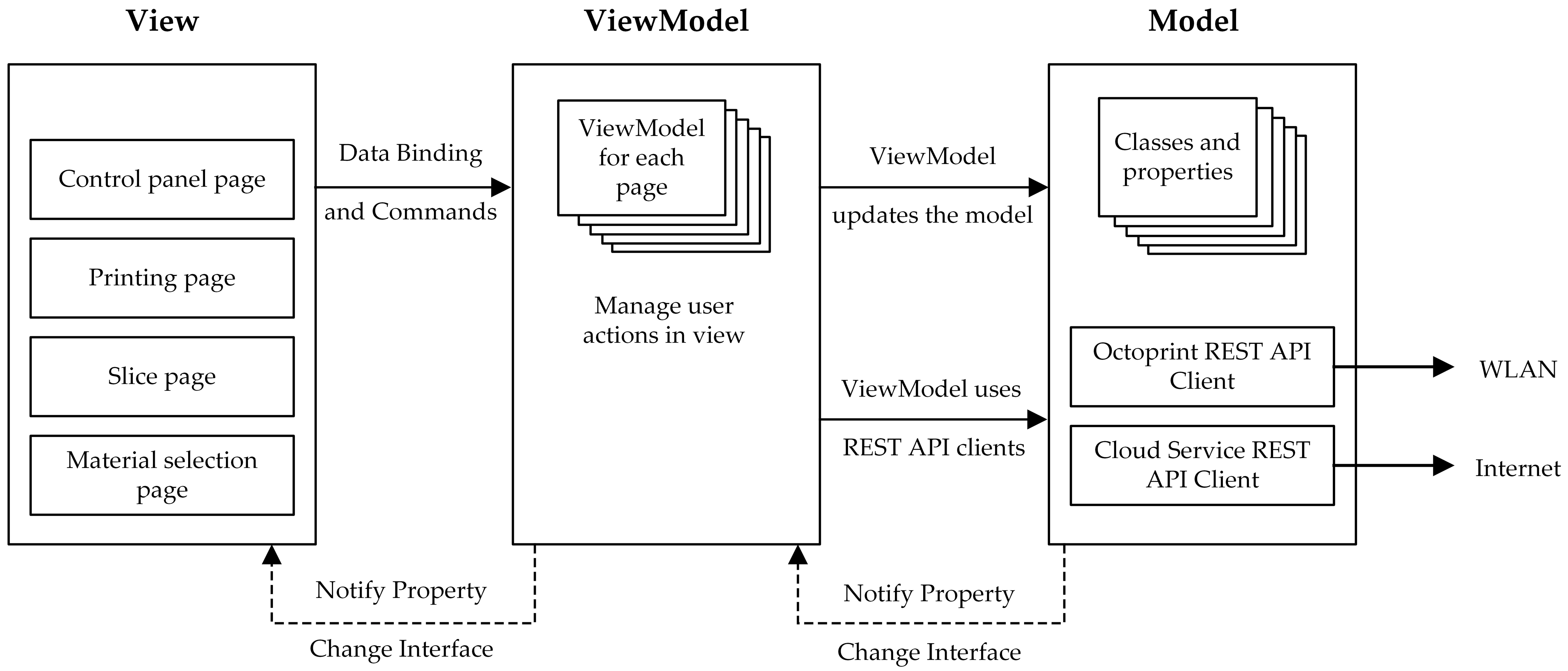
3.3. End-User Application

The first objective of the user application is to handle the basic operations of the production process with the print server. Additionally, when a new job is to be run, the Cloud Service is called upon to generate a new G-code, as mentioned above.
The end-user application is carried out with the multiplatform framework Xamarin.Forms within NET Standard 2.0 to provide more flexibility and adaptability to the maritime industries. Furthermore, being able to use the same application on different smart devices, such as mobile phones, tablets, or computers, makes the technology transfer to the maritime industries more achievable, since they do not have to make a significant investment in additional equipment.
Within the integrated service framework, this application is an approach to the MVVM (Model-View-ViewModel) pattern of software design architectures, where there are three differentiated components: Model, View and ViewModel. The first (Model) provides the data (files and properties) and web access; the ViewModel implements the commands (functions) that the View can execute working with the Model; and the View provides the presentation layer, which interacts with the user [69].
Figure 4 shows the internal structure of the end-user app organized by the main elements.
The user interacts directly on the View. Any action is notified to the ViewModel via “commands”. Then, the ViewModel updates the Model and communicates with the other elements of the architecture. In reverse, any changes to the Model are notified to the View with the “BindingContex” property of the content pages. Thus the ViewModel does not need to update the changes. This notifying method allows independence of the user interfaces from the program logic, which is a key feature of applications based on the MVVM pattern.
Figure 4 also shows that the user interface (View) is composed of four simple pages, as detailed below:
  • Control panel page: the current status of the manufacturing process is periodically monitored. It contains the most basic functional actions (start, stop, etc.) and access to successive pages.
  • Slicing page: new print job setup page. Figure 5 specifies the activities carried out. When the user plans to make a new part, the first step is to configure the process in A0, based on the available materials and quality profiles. Subsequently, after attaching the STL of the part, this data is sent to the Cloud Service, which will carry out activity A1 (detailed in Figure 3, d A1.1 and A1.2 activities). The Local Service is responsible for carrying out the manufacture of the final part from the G-code generated (action A2).
  • Printing page: direct printing without using the Cloud Service. This is possible for 3D printing parts that have already been sliced, as the G-code files are stored in the Local Service once they have been generated.
  • Material selection page: available from the slicing page. It launches a material selection wizard to aid the user to select the most suitable material, as detailed below.

3.3.1. Helping User to Select the Printing Material

Given that a variety of recycled material will be used and that the user is not a material expert, the key to the success of the framework lies in the user being able to choose the most suitable material to print under specified properties.
Material selection is very important in the design and manufacture of parts, defining their properties, performance and reliability [70]. The difficulty is increased when using recycled materials, as their properties are compromised even by the recycling cycles they have undergone. [71]. The proposed architecture takes this into account through a recommendation system that allows the user to select the most suitable material for the manufacturing of a part.
The choice of one material or another is generally made based on its mechanical behaviour and the performance expected in the application. The choice of material is approached as Multi-Criteria Decision-Making (MCDM), where an alternative (material) is selected based on certain criteria (properties) that it must have to meet its requirements, as is stated in [72].
Among the MCDM algorithms, the TOPSIS (Technique for Order Preference by Similarity to an Ideal Solution) method is proposed for its simplicity and good computational efficiency [73], as the intention is for it to be run repeatedly so that the user can test different combinations of requirements.
The TOPSIS method enables the selection of alternatives based on the idea of establishing a ranking between them. This ranking is carried out using the idea of the distance between both ideal and non-ideal alternatives [74]. The service provider determines the evaluation criteria based on which one of the alternatives (materials) is selected. These criteria are commonly defined by technical terms for materials, such as yield strength or surface roughness. This terminology can be confusing for a non-expert user, so these properties could be renamed on the basis of more common characteristics, such as “strength”, “finish”, etc. The method used for this purpose (TOPSIS) comprises the following steps [75]:
Step 1: Construction of the decision matrix and weight allocation (Table 4). Each of the m alternatives A i , with i = 1 , 2 m , is evaluated for each of the n criteria C j ,   with j = 1 , 2 n . Each criterion’s weights are set by the user specifying how much it is estimated that the final part should have that property.
Step 2: Decision matrix normalisation. As the elements of the decision matrix may not be in the same domain (as the criteria can be evaluated in different units of measurement), they are normalised. Likewise, the weights are normalised so that the sum equals unity.
n i j = x i j j = 1 m x i j 2
w j = W j j = 1 n W j
Step 3: Construction of weighted normalised decision matrix. The normalised elements of the decision matrix are weighted.
v i j = w j n i j
Step 4: Obtaining of the ideal positive and negative solution. This would be equivalent to finding the best and the worst material for each criterion.
A + = v 1 + , , v n + = m a x i v i j ,   j J m i n i v i j ,   j J
A = v 1 , , v n = m i n i v i j ,   j J m a x v i j ,   j J
where J is linked to benefit criteria (more is better) and J’ to cost criteria (less is better).
Step 5: Computing the Euclidean distance of each alternative to the ideal and anti-ideal solution.
d i + = j = 1 n ( v i j v j + 2 1 2
d i = j = 1 n ( v i j v j 2 1 2
Step 6: Computation of the proximity to the ideal solution.
R i = d i d i + + d i
The result of the above equation gives a value from 0 to 1 for each alternative   i ; thus, the higher that value, the better the performance of the material for the given requirements. Higher R i value represents a better material for the requirements set.
The results of Steps 3–6 are shown in Table 5.
The TOPSIS method is performed in the user application from the data provided by the Cloud Service. As explained in Section 3.2, this service provides material information in a data structure, which includes a list of the available materials, the criteria being evaluated and the decision matrix.
The graphical representation of the material selection process, guided through the app, as well as the activities carried out are shown in Figure 6a,b respectively.
The user weights the criteria using sliders represented graphically on the material selection screen, as is shown in Figure 6a. The algorithm takes these weights to build the weight criteria vector (B0 in Figure 6b). The TOPSIS method (B1 in Figure 6b) is then run to obtain the material performance vector. This vector contains the results ranked according to their R i -index (Equation (8)). Each material’s performance is shown in the application using progress bars (control input of action B2). Therefore, the user can see graphically which material is best suited and can decide which one to choose. Once the material has been chosen, the process of generating the toolpath code for printing the part is carried out.
The survey responses from companies in the port environment agreed on highlighting ease of use as one of the requirements for effective implementation of 3D printing in the sector. The printing service must exempt non-expert users from other responsibilities, such as software applications maintenance, machine code generation, expert parameter selection, etc.
Given that most 3D printing applications work with pre-established materials, changing to another paradigm with many different types of materials and qualities requires making changes to these applications. Open applications facilitate this adaptation. However, what is most important is that the process is almost transparent to the user. The integrated architecture and the implementation of a “user guide process” for material selection as presented in this section would fulfil the requirement of translating massive plastic qualities into standard printing services.

4. Results and Discussion

This section presents the experiments performed to evaluate the two main strategies proposed in the article regarding the recycling approach and the technological adaptation of 3D printing systems.

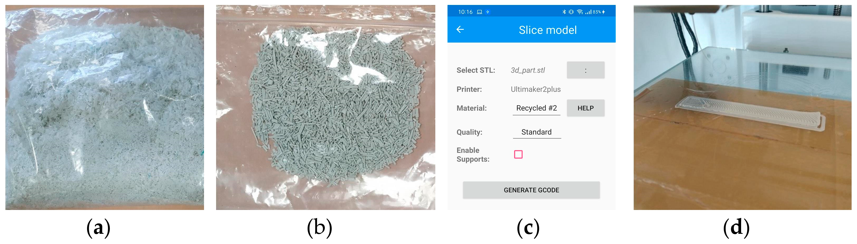
4.1. Material Development Experiment: Strapping Tape Recycling

Based on the types and quantities identified, as detailed in Table 2, different strategies for the recycling of these wastes have been analyzed. Among the three main waste types, polyolefins are semi-crystalline polymers prone to crystallization. This is a drawback when referring to 3D printing, since these materials will warp significantly on cooling. Among them, PP has more potential to be modified for 3D printing applications, and filaments can be commercially found. An experiment to evaluate the novel strategy using polypropylene strapping tape waste (see Table 2) is presented in this section.
There is limited data regarding the amount of recycled content of current products on the market. Most of the recycling done at present involves reintroducing post-industrial wastes (scrap, noncompliance components, etc.) into the process to produce components with the same material. In this case, the wastes are well identified and clean. However, the strapping tape waste is the post-consumer type, in contact with different environments such as marine water, and in most cases it is contaminated. In these cases, apart from the need for sorting, cleaning, and shredding of the wastes, the waste usually shows some degree of degradation and lower molecular weight due to chain scission, which increases the degree of crystallinity [43].
This variability of the properties of post-industrial wastes, such as strapping tape, has led to a common strategy in different industries to incorporate these materials: the use of low recycled contents so as not to disrupt production lines. It has been estimated that less than 5% recycled content is used in automotive, electrical, and agricultural sectors; other sectors, such as packaging, fabricate some products with higher recycled contents of 20% [76]. In this scenario, a novel system to print components with high recycled content based on maritime waste is proposed to the maritime sector.
Experiments were carried out by producing filament with recycled strapping tape in order to be able to make an assessment of the properties of this post-consumer waste. The strapping tape was cleaned only with water, due to minor impurities, and subsequently shredded (Figure 7a). The outcome is a material with a very low apparent density, which is difficult to be properly fed into the extruder. For this reason, it is difficult to produce a filament with a constant diameter. In this case, the first filament is shredded again to get a better granulate to feed the filament line, as can be seen in Figure 7b.
Printing trials were carried out with a standard geometry (central part of the ISO 527 testing specimen). A strong warping effect was detected (Figure 7d). However, this is an already-known effect for standard polypropylene due to the intrinsic thermal contraction properties of this semicrystalline material. Therefore, it is not an effect that can be attributed to the recycled material. Using additives to enhance the flexibility of the material and reduce its overall shrinkage coefficient can improve the printability of PP, as for instance using fillers such as calcium carbonate or blending with more flexible polymers. Here, process parameters have to also be adapted to the modified material.
These trials indicate the potential of using strapping-tape-based PP materials with high recycling content for 3D printing, as long as adequate material developments are made and process parameters are adjusted to the material, as is proposed in the integrated 3D printing framework.

4.2. Classic vs. Integrated Printing Framework for Working with Non-Standard Recycled Filaments

The strategy of using non-standard filament facilitates better valorization, as discussed above. However, this alternative involves more expert and advanced operation when carrying out printing jobs with a classic standard 3D printing environment. The following experiment shows the differences between using a classic printing environment and the one proposed in this article, with both printing the same part with no standard recycled filaments.
  • Standard/Classic 3D printing environment. The steps are as follows: select part file; create a new profile configuration; set—at least—temperature, cooling, deposition rate, retraction, layer height, infill density, brim and print speed configurations; slice; save file to flash memory, insert it in 3D printer, search the machine code file; and print. More than 38 variables have to be set, which often requires expert knowledge (first row in Table 6).
  • Integrated 3D printing environment. The material and quality configurations are carried out by the service provider through the Cloud Service, externalizing the most technical steps for the user. The user steps consist of filing part, material and qualities selection, and printing (Figure 7c), consisting of about four steps (second row in Table 6).
The number of operations and time required to perform a print job are much lower in the case of the integrated 3D printing environment, as the test shows.
Finally, there is no single company in the surveys that identified enough possible products for printing that would have justified the effort of putting the system into practice. However, taking the port area as a whole (and conditioned by the size of the port area), the total number of parts to be printed reaches more feasible values. Therefore, the potential use depends on a “broad system” approach, with many plastics and many different single parts being printed by different companies with very different business activities.

5. Conclusions

The integrated architecture presented in the paper is in line with others reported in the literature [65,66], where open 3D printing resources are used to achieve customized environments that are cost effective and have customized functionalities.
The proposed service-oriented architectures (SOA) [77] could be defined as a pseudo Printing-as-a-Service (PaaS) architecture, because a part of the printing process (configuration and motion control code generation) is executed in the cloud as an external service, but the printing is performed locally. The framework focuses on business in the port and maritime-related economy and commercial activity business scenarios, which are not primarily oriented to the manufacture of parts and products.
Survey data about types and amount of plastic waste (summarized in Table 1) have shown that there is a lot of plastic to be recycled, though there are many types of plastic waste in many types of products. Effort should be made not only to increase the total amount of plastic waste that is recycled but also to try to recycle effectively as many plastic types as possible. The alternative is that the recycling effort could be put into just one type of plastic, and the others could be disregarded, with no attempt at recycling. However, this would not follow Circular Economy principles. That is why this paper considers it important to facilitate, as much as possible, the inclusion of a greater range of plastics in the recycling effort in order to not only recover as many different types of wastes as possible but also offer the end-user a wide variety of recycled material choices to cover their needs.
The paper answers the question about how current 3D printing technology can adapt to and work feasibly with filament made from recycled waste plastic that has a wide range of types and qualities, which is common in maritime and ocean port settings. It does so by proposing a new strategy based not on trying to generate filaments with “standard characteristics” but rather on allowing an unlimited variability of qualities or parameters. To do this, 3D printing applications should be able to work with an unlimited variability of plastic qualities and no regular characteristics in a transparent (easy) way for non-expert users (not experts in materials or 3D printing technology), where the technology automatically adapts to any plastic. The presented framework implements this new strategy and has been tested in a prototype implementation. It has been proven that the number of operations and amount of time required to perform a print job are much lower in the case of the integrated 3D printing environment.

Author Contributions

Conceptualization, J.G. and B.L.; methodology, J.G., D.S. and B.L.; software, J.G., D.S. and B.P.; validation, J.G. and B.L.; formal analysis, J.G., D.S., B.P. and B.L.; investigation, J.G. and B.L.; resources, D.S. and B.P.; data curation, J.G. and D.S.; writing—original draft preparation, J.G. and B.L.; writing—review and editing, J.G., D.S. and B.P.; funding acquisition, J.G. and B.L. All authors have read and agreed to the published version of the manuscript.

Funding

This research was partially funded by the European Regional Development Fund (ERDF): Interreg Atlantic Area programme, grant number EAPA_117/2018” and The APC was funded by the ERDF: Interreg Atlantic Area programme.

Institutional Review Board Statement

Not applicable.

Informed Consent Statement

Not applicable.

Data Availability Statement

Not applicable.

Acknowledgments

The authors express sincere gratitude to project stakeholders of the Vigo node (companies, research institutions and port management) for their valuable data and their support.

Conflicts of Interest

The authors declare no conflict of interest.

References

  1. Jin, S.-J.; Kwon, Y.-J.; Yoo, S.-H. Economic Valuation of Reducing Submerged Marine Debris in South Korea. Appl. Sci. 2020, 10, 6086. [Google Scholar] [CrossRef]
  2. Plastics Europe. Plastics Europe: Association of Plastics Manufacturers; Plastics Europe: Brussels, Belgium, 2020. [Google Scholar]
  3. Law, K.L. Plastics in the Marine Environment. Annu. Rev. Mar. Sci. 2017, 9, 205–229. [Google Scholar] [CrossRef] [Green Version]
  4. Julien, B.; Guillaume, B.; Eleonora, S.; João, S. The Marine Plastic Footprint: Towards a Science-Based Metric for Measuring Marine Plastic Leakage and Increasing the Materiality and Circularity of Plastic; IUCN: Gland, Switzerland, 2020; ISBN 9782831720289. [Google Scholar]
  5. Jambeck, J.R.; Geyer, R.; Wilcox, C.; Siegler, T.R.; Perryman, M.; Andrady, A.; Narayan, R.; Law, K.L. Plastic waste inputs from land into the ocean. Science 2015, 347, 768–771. [Google Scholar] [CrossRef] [PubMed]
  6. Abalansa, S.; El Mahrad, B.; Vondolia, G.K.; Icely, J.; Newton, A. The Marine Plastic Litter Issue: A Social-Economic Analysis. Sustainability 2020, 12, 8677. [Google Scholar] [CrossRef]
  7. LI, W.C.; TSE, H.F.; FOK, L. Plastic waste in the marine environment: A review of sources, occurrence and effects. Sci. Total Environ. 2016, 566–567, 333–349. [Google Scholar] [CrossRef]
  8. Blettler, M.C.M.; Abrial, E.; Khan, F.R.; Sivri, N.; Espinola, L.A. Freshwater plastic pollution: Recognizing research biases and identifying knowledge gaps. Water Res. 2018, 143, 416–424. [Google Scholar] [CrossRef] [Green Version]
  9. Rios Mendoza, L.M.; Balcer, M. Microplastics in freshwater environments: A review of quantification assessment. TrAC Trends Anal. Chem. 2019, 113, 402–408. [Google Scholar] [CrossRef]
  10. Cozar, A.; Echevarria, F.; Gonzalez-Gordillo, J.I.; Irigoien, X.; Ubeda, B.; Hernandez-Leon, S.; Palma, A.T.; Navarro, S.; Garcia-de-Lomas, J.; Ruiz, A.; et al. Plastic debris in the open ocean. Proc. Natl. Acad. Sci. USA 2014, 111, 10239–10244. [Google Scholar] [CrossRef] [Green Version]
  11. Lebreton, L.; Slat, B.; Ferrari, F.; Sainte-Rose, B.; Aitken, J.; Marthouse, R.; Hajbane, S.; Cunsolo, S.; Schwarz, A.; Levivier, A.; et al. Evidence that the Great Pacific Garbage Patch is rapidly accumulating plastic. Sci. Rep. 2018, 8, 4666. [Google Scholar] [CrossRef] [Green Version]
  12. Van Cauwenberghe, L.; Vanreusel, A.; Mees, J.; Janssen, C.R. Microplastic pollution in deep-sea sediments. Environ. Pollut. 2013, 182, 495–499. [Google Scholar] [CrossRef]
  13. Reinold, S.; Herrera, A.; Hernández-González, C.; Gómez, M. Plastic pollution on eight beaches of Tenerife (Canary Islands, Spain): An annual study. Mar. Pollut. Bull. 2020, 151, 110847. [Google Scholar] [CrossRef] [PubMed]
  14. Kanhai, L.D.K.; Gardfeldt, K.; Krumpen, T.; Thompson, R.C.; O’Connor, I. Microplastics in sea ice and seawater beneath ice floes from the Arctic Ocean. Sci. Rep. 2020, 10, 5004. [Google Scholar] [CrossRef] [PubMed] [Green Version]
  15. The Institute of Marine Engineering Science & Technology. Steering towards an Industry Level Response to Marine Plastic Pollution: Roundtable Summary Report; The Institute of Marine Engineering Science & Technology: London, UK, 2019. [Google Scholar]
  16. Hidalgo-Ruz, V.; Gutow, L.; Thompson, R.C.; Thiel, M. Microplastics in the Marine Environment: A Review of the Methods Used for Identification and Quantification. Environ. Sci. Technol. 2012, 46, 3060–3075. [Google Scholar] [CrossRef] [PubMed]
  17. Michel, A.P.M.; Morrison, A.E.; Preston, V.L.; Marx, C.T.; Colson, B.C.; White, H.K. Rapid Identification of Marine Plastic Debris via Spectroscopic Techniques and Machine Learning Classifiers. Environ. Sci. Technol. 2020, 54, 10630–10637. [Google Scholar] [CrossRef] [PubMed]
  18. Lebreton, L.; Andrady, A. Future scenarios of global plastic waste generation and disposal. Palgrave Commun. 2019, 5, 6. [Google Scholar] [CrossRef] [Green Version]
  19. Lebreton, L.C.M.; van der Zwet, J.; Damsteeg, J.-W.; Slat, B.; Andrady, A.; Reisser, J. River plastic emissions to the world’s oceans. Nat. Commun. 2017, 8, 15611. [Google Scholar] [CrossRef] [PubMed]
  20. Emmerik, T.; Schwarz, A. Plastic debris in rivers. WIREs Water 2020, 7, e1398. [Google Scholar] [CrossRef] [Green Version]
  21. Winton, D.J.; Anderson, L.G.; Rocliffe, S.; Loiselle, S. Macroplastic pollution in freshwater environments: Focusing public and policy action. Sci. Total Environ. 2020, 704, 135242. [Google Scholar] [CrossRef]
  22. Barboza, L.G.A.; Cózar, A.; Gimenez, B.C.G.; Barros, T.L.; Kershaw, P.J.; Guilhermino, L. Macroplastics Pollution in the Marine Environment. In World Seas: An Environmental Evaluation; Elsevier: Amsterdam, The Netherlands, 2019; pp. 305–328. ISBN 9780128050521. [Google Scholar]
  23. Faure, F.; Saini, C.; Potter, G.; Galgani, F.; de Alencastro, L.F.; Hagmann, P. An evaluation of surface micro- and mesoplastic pollution in pelagic ecosystems of the Western Mediterranean Sea. Environ. Sci. Pollut. Res. 2015, 22, 12190–12197. [Google Scholar] [CrossRef]
  24. Gago, J.; Booth, A.M.; Tiller, R.; Maes, T.; Larreta, J. Microplastics Pollution and Regulation. In Handbook of Microplastics in the Environment; Springer International Publishing: Cham, Switzerland, 2020; pp. 1–27. [Google Scholar]
  25. Barboza, L.G.A.; Frias, J.P.G.L.; Booth, A.M.; Vieira, L.R.; Masura, J.; Baker, J.; Foster, G.; Guilhermino, L. Microplastics Pollution in the Marine Environment. In World Seas: An Environmental Evaluation; Elsevier: Amsterdam, The Netherlands, 2019; pp. 329–351. ISBN 9780128050521. [Google Scholar]
  26. Gigault, J.; Halle, A.; Baudrimont, M.; Pascal, P.-Y.; Gauffre, F.; Phi, T.-L.; El Hadri, H.; Grassl, B.; Reynaud, S. Current opinion: What is a nanoplastic? Environ. Pollut. 2018, 235, 1030–1034. [Google Scholar] [CrossRef]
  27. Lazarevic, D.; Aoustin, E.; Buclet, N.; Brandt, N. Plastic waste management in the context of a European recycling society: Comparing results and uncertainties in a life cycle perspective. Resour. Conserv. Recycl. 2010, 55, 246–259. [Google Scholar] [CrossRef]
  28. Hee, J.; Schlögel, K.; Lechthaler, S.; Plaster, J.; Bitter, K.; Blank, L.M.; Quicker, P. Comparative Analysis of the Behaviour of Marine Litter in Thermochemical Waste Treatment Processes. Processes 2020, 9, 13. [Google Scholar] [CrossRef]
  29. Merkl, A.; Stuchtey, M. Stemming the Tide: Land-Based Strategies for a Plastic- Free Ocean; Ocean Conservancy and McKinsey Center for Business and Environment. 2015, pp. 1–47. Available online: https://oceanconservancy.org/wp-content/uploads/2017/04/full-report-stemming-the.pdf (accessed on 1 February 2021).
  30. Hopewell, J.; Dvorak, R.; Kosior, E. Plastics recycling: Challenges and opportunities. Philos. Trans. R. Soc. B Biol. Sci. 2009, 364, 2115–2126. [Google Scholar] [CrossRef] [Green Version]
  31. Issifu, I.; Sumaila, U.R. A Review of the Production, Recycling and Management of Marine Plastic Pollution. J. Mar. Sci. Eng. 2020, 8, 945. [Google Scholar] [CrossRef]
  32. Löhr, A.; Savelli, H.; Beunen, R.; Kalz, M.; Ragas, A.; Van Belleghem, F. Solutions for global marine litter pollution. Curr. Opin. Environ. Sustain. 2017, 28, 90–99. [Google Scholar] [CrossRef] [Green Version]
  33. Syberg, K.; Nielsen, M.B.; Westergaard Clausen, L.P.; van Calster, G.; van Wezel, A.; Rochman, C.; Koelmans, A.A.; Cronin, R.; Pahl, S.; Hansen, S.F. Regulation of plastic from a circular economy perspective. Curr. Opin. Green Sustain. Chem. 2021, 29, 100462. [Google Scholar] [CrossRef]
  34. Schyns, Z.O.G.; Shaver, M.P. Mechanical Recycling of Packaging Plastics: A Review. Macromol. Rapid Commun. 2021, 42, 2000415. [Google Scholar] [CrossRef] [PubMed]
  35. Tesfaye, W.; Kitaw, D. Conceptualizing reverse logistics to plastics recycling system. Soc. Responsib. J. 2020. ahead-of-print. [Google Scholar] [CrossRef]
  36. European Commission. A European Strategy for Plastics in a Circular Economy; European Commission: Brussels, Belgium, 2018. [Google Scholar]
  37. OCEANETS. Technological Approaches for Circular Economy Solutions in Terms of Prevention, Recover, Re-Use and Recycle of Fishing Gears to Obtain Added-Value Products in the Textile Industry. Available online: http://oceanets.eu/ (accessed on 17 February 2021).
  38. marGnet. Mapping and Recycling of Marine Litter and Ghost Nets on the Sea-Floor. Available online: http://www.margnet.eu/ (accessed on 17 February 2021).
  39. NetTag. Tagging Fishing Gears and Enhancing on Board Best-Practices to Promote Waste Free Fisheries. Available online: https://net-tag.eu/?lang=en (accessed on 17 February 2021).
  40. CleanAtlantic. Tackling Marine Litter in the Atlantic Area. Available online: http://www.cleanatlantic.eu/ (accessed on 17 February 2021).
  41. CircularSeas. Turning Ocean Plastic Waste into Green Products for Maritime Industries. Available online: https://circularseas.com/ (accessed on 17 February 2021).
  42. Kostidi, E.; Nikitakos, N. Exploring the Potential of 3D Printing of the Spare Parts Supply Chain in the Maritime Industry. In Safety of Sea Transportation; CRC Press: London, UK, 2017; pp. 171–178. ISBN 978-1-315-09908-8. [Google Scholar]
  43. Aurrekoetxea, J.; Sarrionandia, M.A.; Urrutibeascoa, I.; Maspoch, M.L. Effects of recycling on the microstructure and the mechanical properties of isotactic polypropylene. J. Mater. Sci. 2001, 36, 2607–2613. [Google Scholar] [CrossRef]
  44. Atlantic Area. Projects. Available online: https://www.atlanticarea.eu/page/48 (accessed on 17 February 2021).
  45. Kostidi, E.; Nikitakos, N. Is It Time for the Maritime Industry to Embrace 3d Printed Spare Parts? TransNav Int. J. Mar. Navig. Saf. Sea Transp. 2018, 12, 557–564. [Google Scholar] [CrossRef]
  46. Dizon, J.R.C.; Valino, A.D.; Souza, L.R.; Espera, A.H.; Chen, Q.; Advincula, R.C. Three-dimensional-printed molds and materials for injection molding and rapid tooling applications. MRS Commun. 2019, 9, 1267–1283. [Google Scholar] [CrossRef]
  47. Minguella-Canela, J.; Planas, S.M.; Ayats, J.R.G.; de los Santos López, M.A. Study and comparison of the different costs’ schema associated to geometry, material and processing between 3D printing, injection molding and machining manufacturing technologies. Procedia Manuf. 2019, 41, 280–287. [Google Scholar] [CrossRef]
  48. Pakkanen, J.; Manfredi, D.; Minetola, P.; Iuliano, L. About the Use of Recycled or Biodegradable Filaments for Sustainability of 3D Printing. In Sustainable Design and Manufacturing 2017; Campana, G., Howlett, R.J., Setchi, R., Cimatti, B., Eds.; Smart Innovation, Systems and Technologies; Springer International Publishing: Cham, Switzerland, 2017; Volume 68, pp. 776–785. ISBN 978-3-319-57077-8. [Google Scholar]
  49. ISO. Additive Manufacturing—General Principles—Part 2: Overview of Process Categories and Feedstock; ISO 17296-2:2015; ISO: Geneva, Switzerland, 2015. [Google Scholar]
  50. Mohamed, O.A.; Masood, S.H.; Bhowmik, J.L. Optimization of fused deposition modeling process parameters: A review of current research and future prospects. Adv. Manuf. 2015, 3, 42–53. [Google Scholar] [CrossRef]
  51. Wang, X.; Jiang, M.; Zhou, Z.; Gou, J.; Hui, D. 3D printing of polymer matrix composites: A review and prospective. Compos. Part B Eng. 2017, 110, 442–458. [Google Scholar] [CrossRef]
  52. Birtchnell, T.; Urry, J. A Brief History of 3D Printing. In A New Industrial Future? 1st ed.; Routledge: New York, NY, USA, 2016; pp. 18–42. [Google Scholar]
  53. ISO. Automation Systems and Integration—Numerical Control of Machines—Program Format and Definitions of address Words—Part 1: Data Format for Positioning, Line Motion and Contouring Control Systems; ISO 6983-1:2009; ISO: Geneva, Switzerland, 2009. [Google Scholar]
  54. Brown, A.C.; de Beer, D. Development of a stereolithography (STL) slicing and G-code generation algorithm for an entry level 3-D printer. In Proceedings of the 2013 Africon, Pointe-Aux-Piments, Mauritius, 9–12 September 2013; pp. 1–5. [Google Scholar]
  55. Ranellucci, A. Reprap, Slic3r and the Future of 3D Printing. In Low-cost 3D Printing for Science, Education & Sustainable Development; ICTP—The Abdus Salam International Centre for Theoretical Physics: Trieste, Italy, 2013; pp. 75–82. ISBN 92-95003-48-9. [Google Scholar]
  56. Mohd Ariffin, M.K.A.; Sukindar, N.A.; Baharudin, B.T.H.T.; Jaafar, C.N.A.; Ismail, M.I.S. Slicer Method Comparison Using Open-source 3D Printer. IOP Conf. Ser. Earth Environ. Sci. 2018, 114, 012018. [Google Scholar] [CrossRef]
  57. Baumann, F.; Bugdayci, H.; Grunert, J.; Keller, F.; Roller, D. Influence of slicing tools on quality of 3D printed parts. Comput.-Aided Des. Appl. 2016, 13, 14–31. [Google Scholar] [CrossRef]
  58. Rehmani, M.A.A.; Jaywant, S.A.; Arif, K.M. Study of Microchannels Fabricated Using Desktop Fused Deposition Modeling Systems. Micromachines 2020, 12, 14. [Google Scholar] [CrossRef] [PubMed]
  59. Baumann, F.W.; Kopp, O.; Roller, D. Abstract API for 3D printing hardware and software resources. Int. J. Adv. Manuf. Technol. 2017, 92, 1519–1535. [Google Scholar] [CrossRef]
  60. Andrade, T.F.; Abreu, P.; Restivo, M.T.; Chouzal, M.F.; Santos, B.F.; Rodrigues, J. Enhancing a 3D Printer with Online Access. Int. J. Interact. Mob. Technol. IJIM 2017, 11, 44. [Google Scholar] [CrossRef] [Green Version]
  61. Häußge, G. OctoPrint. Available online: https://octoprint.org/ (accessed on 18 February 2021).
  62. Horvath, J. Driving Your Printer: G-code. In Mastering 3D Printing; Apress: Berkeley, CA, UAA, 2014; pp. 65–76. [Google Scholar]
  63. Free and Open-source Control Software for 3-D Motion and Processing. J. Open Res. Softw. 2016, 4, e2. [CrossRef] [Green Version]
  64. Kostidi, E.-E.; Nikitakos, N. Additive manufacturing of Spare parts in the Maritime Industry in the digital era. In Proceedings of the Annual conference of the International Association of Maritime Economists (IAME), Athens, Greece, 25–28 June 2019. [Google Scholar]
  65. Mai, J.; Zhang, L.; Tao, F.; Ren, L. Customized production based on distributed 3D printing services in cloud manufacturing. Int. J. Adv. Manuf. Technol. 2016, 84, 71–83. [Google Scholar] [CrossRef]
  66. Paszkiewicz, A.; Bolanowski, M.; Budzik, G.; Przeszłowski, Ł.; Oleksy, M. Process of Creating an Integrated Design and Manufacturing Environment as Part of the Structure of Industry 4.0. Processes 2020, 8, 1019. [Google Scholar] [CrossRef]
  67. Li, L.; Chou, W.; Zhou, W.; Luo, M. Design Patterns and Extensibility of REST API for Networking Applications. IEEE Trans. Netw. Serv. Manag. 2016, 13, 154–167. [Google Scholar] [CrossRef]
  68. Häußge, G. REST API. Available online: https://docs.octoprint.org/en/master/api/index.html (accessed on 17 February 2021).
  69. Petzold, C. Creating Mobile Apps with Xamarin.Forms; Microsoft Press: Redmond, WA, USA, 2016; ISBN 978-1-5093-0297-0. [Google Scholar]
  70. Deng, Y.-M.; Edwards, K.L. The role of materials identification and selection in engineering design. Mater. Des. 2007, 28, 131–139. [Google Scholar] [CrossRef]
  71. Mikula, K.; Skrzypczak, D.; Izydorczyk, G.; Warchoł, J.; Moustakas, K.; Chojnacka, K.; Witek-Krowiak, A. 3D printing filament as a second life of waste plastics—A review. Environ. Sci. Pollut. Res. 2020, 28, 12321–12333. [Google Scholar] [CrossRef] [PubMed]
  72. Bhosale, S.B.; Bhowmik, S.; Ray, A. Multi Criteria Decision Making For Selection Of Material Composition For Powder Metallurgy Process. Mater. Today Proc. 2018, 5, 4615–4620. [Google Scholar] [CrossRef]
  73. Rehman, S.; Khan, S.A.; Alhems, L.M. Application of TOPSIS Approach to Multi-Criteria Selection of Wind Turbines for On-Shore Sites. Appl. Sci. 2020, 10, 7595. [Google Scholar] [CrossRef]
  74. Hwang, C.-L.; Yoon, K. Multiple Attributes Decision Making Methods and Applications; Springer: Berlin, Germany, 1981. [Google Scholar]
  75. Ceballos, B.; Lamata, M.T.; Pelta, D.; Sanchez, J.M. El método topsis relativo vs. Absoluto. Rev. Electrón. Comun. Trab. ASEPUMA 2013, 14, 181–192. [Google Scholar]
  76. The Waste and Resources Action Programme. Plastics Market Situation Report 2019; The Waste and Resources Action Programme: Banbury, UK, 2021. [Google Scholar]
  77. Baumann, F.; Roller, D. Additive Manufacturing, Cloud-Based 3D Printing and Associated Services—Overview. J. Manuf. Mater. Process. 2017, 1, 15. [Google Scholar] [CrossRef] [Green Version]
Figure 1. Integrated service architecture.
Applsci 11 03787 g001
Figure 2. Local service constitution and link to end-user app.
Applsci 11 03787 g002
Figure 3. IDEF0 of the whole slicing process (configure and slice).
Applsci 11 03787 g003
Figure 4. MVVM approach on end-user application.
Applsci 11 03787 g004
Figure 5. IDEF0 of the slicing process from user decisions to final part.
Applsci 11 03787 g005
Figure 6. Material selection support process. (a) Graphic representation of the selection process (View); (b) IDEF0 diagram (ViewModel and Model).
Applsci 11 03787 g006
Figure 7. Strapping tape recycling experiment: (a) Shredded strapping tape from the waste; (b) result of a second shred; (c) end-user application; (d) warping effect of the strapping-tape-based material during printing trials.
Applsci 11 03787 g007
Table 1. Summary of the main plastic waste data.
WasteQuantity (Tn)Plastic TypeCurrent Waste Management
Nets1681.34HDPE, PPSale to plastic recycling company
Containers454.10PET, HDPE, PP, LDPEContract with private company for collection, transport and management of the waste
Films135.73LDPEMSW 1 or sale to plastic recycling company
Bags130.00LDPECompacted and managed as MSW 1
Ropes100.00HDPE, PPSale to company for reuse
Fragile packaging31.28EPS (Expanded PolyStyrene)Collection by the port manager
Strapping tapes29.56PPMSW 1 or sale to plastic recycling company
1 MSW = Municipal Solid Waste.
Table 2. Quantity of waste identified by type of plastic.
Plastic TypeQuantity (Tn)
HDPE1429.04
PP365.83
LDPE265.73
PET62.04
EPS31.28
Table 3. Summary of the commercial products identified for replacement by green (recycled) ones.
PartQuantity in Demand
(by Year)
Manufacturing
Technology
Prototypes-3D Printing
Pallets3545 itemsInjection
Spare parts
(Bearing carriers)
-
(44 items)
3D Printing
Film60,480 kgOther
Bags1500 itemsOther
Roller stops300 items3D Printing
Rack tubes50 items3D Printing
Special parts of a jetty, such as curved or trim elements-3D Printing
Bottles270 itemsInjection
Containers1800 itemsInjection/Other
or 3D Printing
Support components1000 items3D Printing
Plastic pipes-Injection
Table 4. Decision matrix and weights for each criterion.
Criterion 1Criterion 2Criterion n
Material 1 x 11 x 12 x 1 n
Material 2 x 21 x 22 x 2 n
Material m x m 1 x m 2 x m n
Criterion weight W 1 W 2 W n
Table 5. Normalised matrix, ideal and anti-ideal solution, Euclidean distances and performances.
Criterion 1Criterion 2Criterion n d i + d i R i
Material 1 v 11 v 12 v 1 n d 1 + d 1 R 1
Material 2 v 21 v 22 v 2 n d 2 + d 2 R 2
Material m v m 1 v m 2 v m n d m + d m R m
Normalised weight w 1 w 2 w n
A + v 1 + v 2 + v n +
A v 1 v 2 v n
Table 6. Experimental evaluation of standard and integrated 3D printing environments with non-standard filament.
StepsVariablesTime to Print (min)User 3D Technology Knowledge
Standard153815High
Integrated432Low
Publisher’s Note: MDPI stays neutral with regard to jurisdictional claims in published maps and institutional affiliations.

