1. Introduction
In the development of driving automation, the response time of the driver for external stimuli is crucial. Even though driving people have the same cognition and control ability, under larger mental loads or distracted, the driving operations may appear seriously out of control [
1,
2,
3,
4,
5]. Therefore, in addition to the need for an optimized strategy for the response of the driver reaction time in an automated driving system, the automatic pressure regulating valve (APRV) as an actuator, its structure constructed for the safety of commercial vehicle driving, and the development of automatic driving is particularly critical.
The intelligentization of the brake system in commercial vehicles directly affects the development of driving automation, as the brake system in commercial vehicles needs suitable APRV to meet the requirements of driving automation and adapt to different levels of driving automation. At present, the structural research of the APRV has mainly focused on the optimization and improvement of existing products and the analysis of the influence of the structural parameters of the APRV on its response characteristics [
6], while research on the structural design and working principle of the APRV is relatively rare. Based on the braking requirements of the electronically controlled pneumatic brake (ECPB) system of commercial vehicles, Wu S et al. proposed a new overall structure scheme of the APRV. Through a theoretical analysis, mathematical modeling and simulation, the pressure response characteristics and flow characteristics of the APRV were analyzed [
7,
8]. Bo L designed a high−precision pneumatic proportional pressure valve and analyzed the influence of its main physical and geometric parameters on its dynamic characteristics and control performance through a nonlinear dynamics model [
9]. Sun H et al. designed an electromagnetic control pneumatic brake valve that regulated the air pressure by changing the current intensity proportionally, thus improved the reliability of the pneumatic brake system [
10]. You M et al. established a mathematic model of a proportional relay valve in MATLAB/Simulink and verified the model through an open loop experiment, analyzed the effects of the main physical and geometrical parameters on the characteristics of the valve and studied the feasibility of using a pneumatic proportional valve as a pressure regulator in order to improve the pneumatic brake system of vehicles [
11]. Cazzola G J et al. established a mathematical model of the ECPBS of commercial vehicles, simulated the response characteristics of the relay valve and the brake chamber and analyzed the influence of the internal structural parameters of the relay valve on the braking response time [
12]. Zhao et al. studied the effects of the structural parameters on the static electromagnetic characteristics of high-speed solenoid valves [
13].
The research of APRV has mainly focused on the control strategy and electric circuit. Hu Dawei et al. proposed the MPC, LQT and LPV control models in order to reduce the response time of the pressure regulating valve in the ECPBS of commercial vehicles, which was verified by the test bench and compared with the data of a PID control model, thus effectively improving the response speed of the pressure-regulating valve and the performance of the ECPBS of commercial vehicles [
14,
15,
16]. Bin Zhang et al., proposed a self-correcting PWM control algorithm for high-speed on/off valves to maintain and improve the original dynamic performance under changing pressures [
17]. Sorli M et al. built a nonlinear dynamic model of a pneumatic proportional pressure valve (now Parker P3P-R) under several operating conditions and downstream loads to simulate its dynamic behavior in the time and frequency domains and validated the proposed model through experiments [
18]. Han J C et al. established static and dynamic simulation models of proportional relay valves of a pneumatic EBS (Electronic Braking System) for commercial vehicles with MATLAB/Simulink; then, the simulation models were verified to be correct on a test bench and, thus, can be used for the development of hardware and control algorithms of a pneumatic EBS for commercial vehicles [
19,
20]. Miller J I designed a new pneumatic valve to improve the response of air-actuated brakes for heavy vehicles to demand pressures generated during electronically controlled braking [
21]. P X Li et al. used a double voltage driving circuit to reduce the switching time and delay time of the high-speed on/off valve, and hence, the response characteristics and the control performance were optimized [
22,
23]. Lee designed and manufactured an electronic valve driving circuit with fast response characteristics by using a three-power source. The new circuit shortened the switching delay time from 5 ms to 1.55 ms. Therefore, the hydraulic system with the new circuit showed excellent position tracking control performance [
24].
The above research was mainly aimed at the improvement of the structure of the existing APRV or the optimization of the control strategy. The working conditions were relatively fixed in this research, and there has been no in-depth study on whether the structure of the APRV can cope with the driving conditions under special circumstances. In order to adapt to the development of driving automation and intelligentization of the brake system, the brake system in commercial vehicles is in urgent need of an APRV that can adapt to the development of driving automation and an intelligent brake system. Therefore, this paper studies the structure configurations of the APRV to ensure that the structure configuration of the APRV can adapt to more dangerous driving conditions, so as to better guarantee the driving safety of vehicles and the development of driving automation.
Based on the classification of driving automation proposed by the SAE (Society of Automotive Engineers) and the working principle of the ECPBS of commercial vehicles, four structural configurations of APRV are proposed. The simulation model for the APRV of different structural configurations is established in AMESim, and the working condition in which the driver fails to apply sufficient braking force is simulated. Then, the pressure regulation characteristics of the APRV under different control conditions and during the switch between these conditions is studied. The correctness and the reliability of the simulation model are verified through the test bench for the pressure regulation characteristics of the APRV of different structural configurations. Finally, through simulation and tests, the pressure regulation characteristics of the APRV of different structural configurations under different control conditions are studied, and the suitable levels in the SAE automated driving classification for the APRV of different structural configurations are determined; thus, the theoretical underpinning to improve driving safety and develop driving automation is provided.
2. Pressure Regulating Requirements and Control Modes of the APRV in the ECPBS of Commercial Vehicles
The ECPBS of commercial vehicle is a new type of brake system that meets the requirements of automated driving. The electronic control mode is added on the basis of retaining the traditional braking circuit, and the ECPBS provides decent solutions to many problems in the traditional pneumatic brake system [
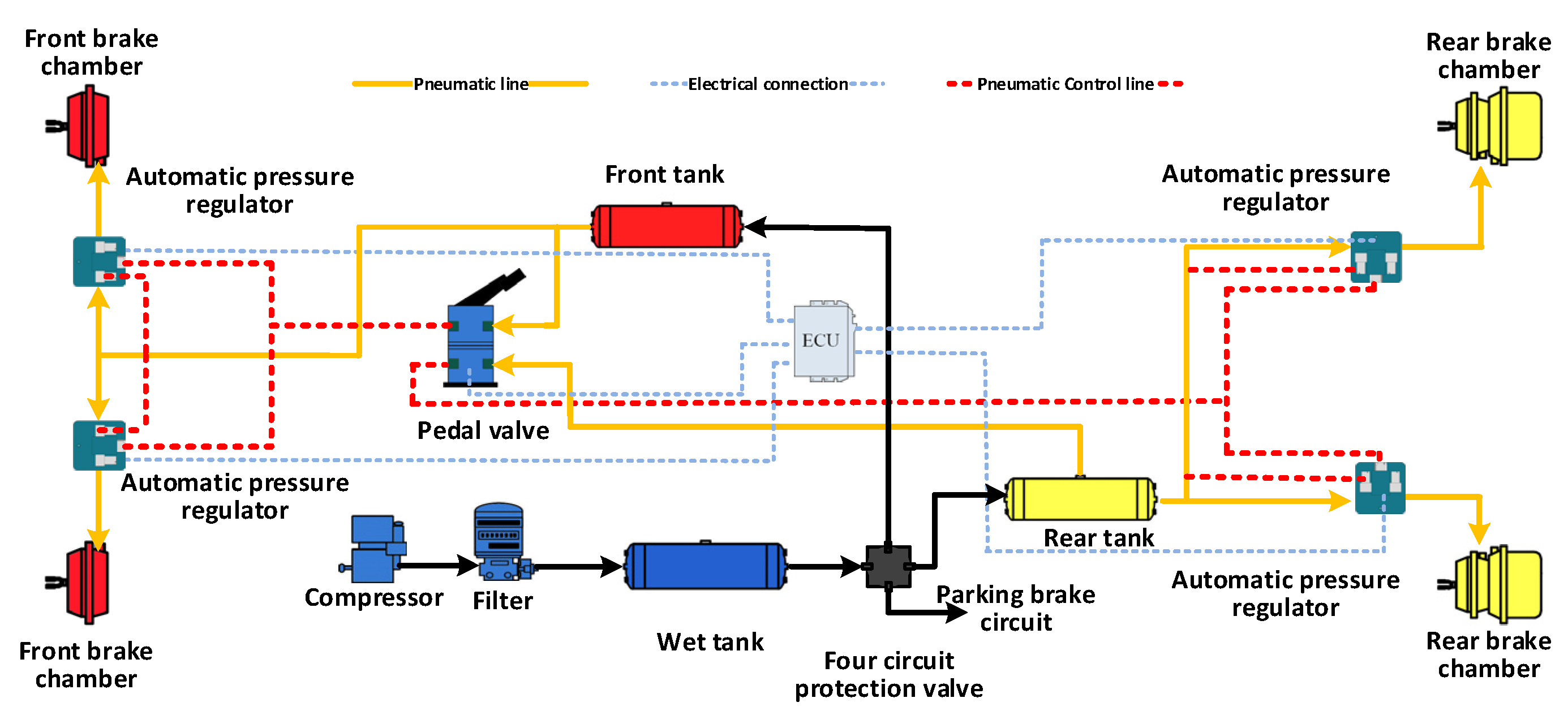
25], thus ensuring driving safety and driving comfort. As depicted in
Figure 1, the APRV is the core pressure-regulating component in the ECPBS. As the key component to ensure driving safety, its structure configuration and the pressure-regulating function must meet the braking requirements of the driver and the automated driving system. Moreover, the APRV should be able to operate under different control modes to ensure driving safety under different working conditions.
2.1. Pressure Regulating Requirements of the APRV in the ECPBS of Commercial Vehicles
According to the description of the six levels of driving automation proposed by the SAE (Society of Automotive Engineers) in 2018, the APRV should realize the following functions:
(1) The APRV can regulate the braking pressure when the vehicle is driven manually by the driver (meeting the requirements of levels 0–2 in the automated driving classification of the SAE).
(2) The APRV can regulate the braking pressure when the vehicle is driven automatically (meeting the requirements of levels 3–5 in the automated driving classification of the SAE).
(3) The APRV can regulate the braking pressure when the vehicle switches between automated driving mode and manual driving mode (meeting the requirements of levels 1–5 in the automated driving classification of the SAE).
(4) The APRV can regulate the braking pressure when the electronic control system fails (meeting the requirements of levels 1–5 in the automated driving classification of the SAE).
(5) The APRV can regulate the braking pressure when the braking pressure is insufficient in the manual driving mode (meeting the requirements of levels 3–5 in the automated driving classification of the SAE).
2.2. Control Modes of the APRV in the ECPBS of Commercial Vehicles
According to the working principle of the ECPBS of commercial vehicles and the pressure regulating requirements of the APRV, as the core pressure-regulating component of the ECPBS, the APRV should be able to be controlled directly by the driver or the automated driving system. Additionally, the APRV can operate during the switch of these two control modes or operate under a coupled control mode. Therefore, the control modes of the APRV include the manual control mode, electronic control mode and coupled control mode. The definitions are as follows:
(1) Manual control mode: The pressure regulation is done by the pedal control applied by the driver.
(2) Electronic control mode: The pressure regulation is done by the automated driving system via a control signal without the interference of the driver.
(3) Coupled control mode: A combination of the manual control mode and the electronic control mode, the pressure regulation is done by both the driver and the automated driving system.
3. Theoretical Analysis and Structural Configurations of the APRV in the ECPBS of Commercial Vehicles
3.1. Mathematical Model of the APRV
The mathematical model of the APRV includes a solenoid valve subsystem and relay valve subsystem. The key points of the model are the movement of the valve core and piston and the relationship between the pressure and mass flow rate. The movement of the valve core in the solenoid valve is determined by electromagnetic force, spring force, damping force and flow force. The dynamic equation of the valve core of the solenoid valve is as follows:
where
is the electromagnetic force (N),
is the mass of the valve core in the solenoid valve,
is the stiffness of the spring (N/m),
is the coefficient of the viscous damping (N·m
−1·s
−1),
is the pressure of the inlet port (Pa),
is the pressure of the control cavity (Pa),
is the effective radius of the flow area (m),
is the displacement of the valve core in the solenoid valve (m) and
is the initial shape variable of the spring (m).
The movement of the piston and valve core in the relay valve includes the processes of pressurization and decompression. In the pressurization process of the APRV, the piston and the valve core stay in contact and, hence, can be considered as a whole. The dynamic equation of the piston and valve core is as follows:
In the process of decompression, the piston and the valve core detach. The dynamic equation of the piston is as follows:
where
is the displacement of the piston (m),
is the mass of the piston in the relay valve (kg),
is the mass of the valve core in the relay valve (kg),
is the upper surface area of the piston (m
2),
is the lower surface area of the piston (m
2),
is the stiffness of the spring (N/m),
is the preload force of the spring (m),
is the viscous damping coefficient of the piston (N·m
−1·s
−1),
is the viscous damping coefficient of the valve core (N·m
−1·s
−1) and
is the friction force (N).
The processes of pressurization and decompression in the APRV can be considered the inflation and the deflation processes of a variable-volume chamber. These processes happen in an extremely short time and, therefore, can be regarded as adiabatic processes, so the relationship between the pressure and mass flow rate [
6] is as follows:
where
is the volume of the chamber (m
3),
is the inlet mass flow rate (kg/s),
is the outlet mass flow rate (kg/s),
is the adiabatic index and
is the temperature of the air that flows through the orifice (K).
3.2. Structural Configurations of the APRV
Based on the working principle of the ECPBS of commercial vehicles shown in
Figure 1, the pressure-regulating requirements and the control modes of the APRV, four structural configurations of the APRV (shown in
Figure 2) are proposed.
First of all, the APRV must ensure independent pressure regulation by the driver or the automated driving system, namely support for the manual control mode and electronic control mode. Additionally, through the optimization of the structural configuration and the control strategy, the coupled control mode and the switch between the two control modes can be realized.
As shown in
Figure 2, the lower valve bodies in the four structural configurations are the same, and the electronic control circuits are similar. In these configurations, the pressure regulation is done by the control of high-speed solenoid valves, which serve as switch valves or high-speed inlet/exhaust valves, and the difference is that different configurations apply different types of solenoid valves, namely normally open (NO) ones and normally closed (NC) ones. Correspondingly, the manual control circuit of each configuration differs. In configuration I, the manual control circuit and the electronic control circuit are in parallel. In configurations II and III, the switch between the control modes is done by the control of the switch valves, which are, respectively, a two-position three-way solenoid valve in configuration II and a three-position three-way solenoid valve in configuration III. In configuration IV, a high-speed inlet valve is applied between the inlet port and the lower valve body on the basis of configuration II. Therefore, two electronic control circuits are set up to implement the coupled control mode. The configurations are elucidated in
Table 1.
4. Test Bench for the Pressure Regulation Characteristics and Control Conditions of the APRV of Different Structural Configurations in the ECPBS of Commercial Vehicles
4.1. Equivalent Models of the APRV of Different Structural Configurations and the Test Bench for the Pressure Regulation Characteristics
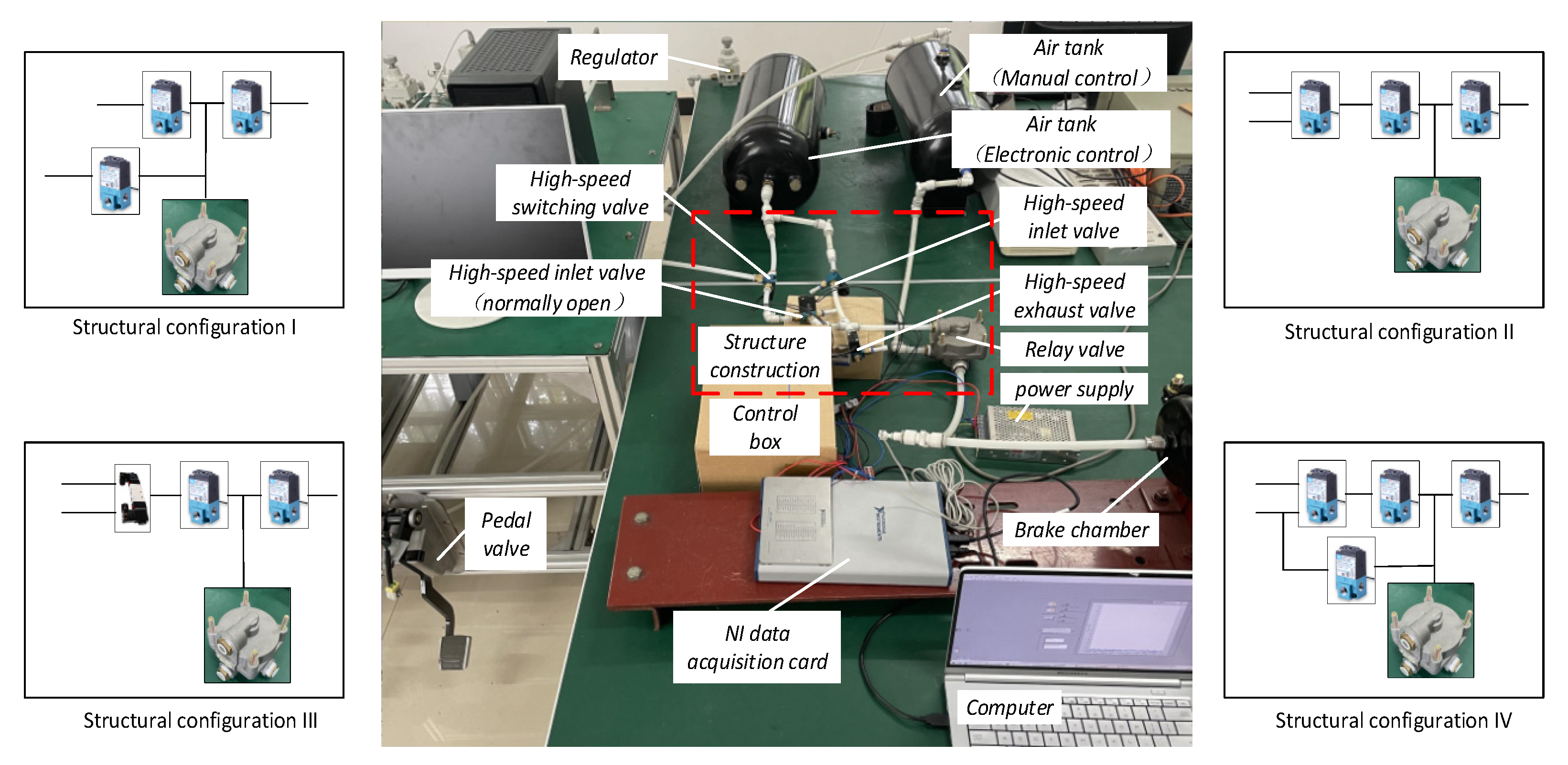
To analyze the pressure regulation characteristics of the APRVs of different structural configurations under different control conditions, a test bench for the pressure regulation characteristics of the APRVs of different structural configurations was built. As shown in
Figure 3, a pedal valve, the equivalent models, air tanks, a computer, an NI acquisition card, etc. were included in the test bench, and the specific piping and components of the test bench were consistent with that of the ECPBS (
Figure 1) to ensure compliance with the requirements of the braking system. The pressure signal and the control signal were acquired by the NI acquisition card and processed in real time, and thus, the test for equivalent models of the APRV of different structural configurations could be carried out.
The test covers a pressurization–decompression test under manual control, a pressurization–decompression test under electronic control, a switch test between the manual and electronic control modes during pressurization and a switch test between the manual and coupled control modes during pressurization. Considering the significant effect of the control strategy on the pressure response, the equivalent model is set to operate at the full open condition or full close condition to avoid such influence. The switch tests between modes are planned to simulate the conditions in which the brake force is insufficient owing to the false operation of the driver or a malfunction of the pedal valve so that the automated driving system takes over and switches the control mode to the electronic control mode or coupled control mode. A stopping block is installed on the pedal valve to set the opening of the valve at a fixed point to simulate a condition in which the brake force is insufficient and make sure the pressure is the same before the control mode is switched to the electronic control mode or coupled control mode.
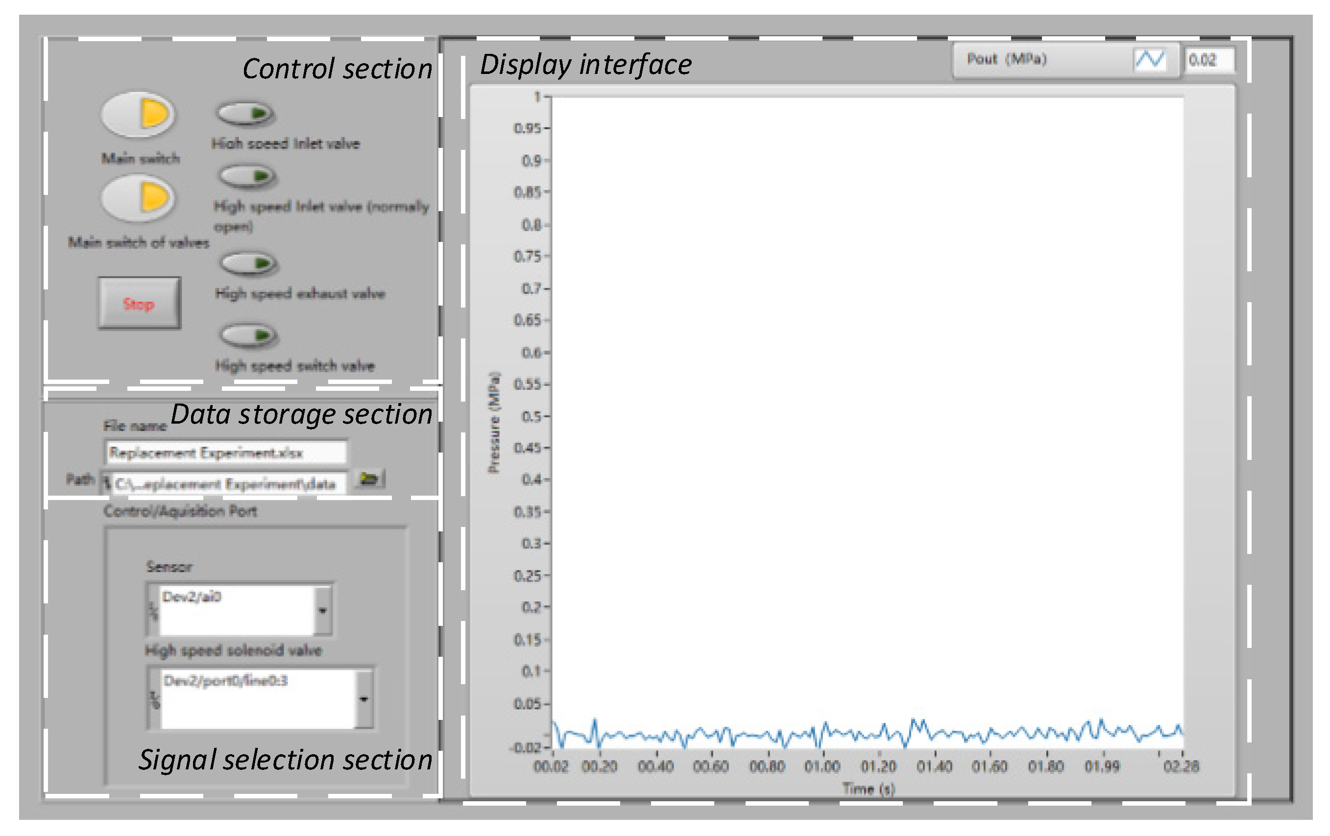
The software interface of the test bench was developed with LabVIEW. As shown in
Figure 4, the interface is made up of a display section, control section, data storage section and signal selection section.
4.2. Control Conditions of the Test for the Pressure Regulation Characteristics of the APRV of Different Structural Configurations in the ECPBS of Commercial Vehicles
The test is done by replacing the equivalent models of the APRV of different structural configurations. In the test bench, the air source pressure is set to 700 kPa, the power source voltage is 220 V, the nominal voltage of the solenoid valve is 24 V and the voltage of the control signal is 5 V.
4.2.1. Control Conditions of the Test for the Pressure Regulation Characteristics of the APRV of Structural Configuration I
The equivalent model of the APRV of the structural configuration is connected to the test bench, and the pressure is controlled by the pedal valve and the switch of the high-speed solenoid valves. The control condition of each solenoid valve is shown in
Table 2.
In the pressurization–decompression test under manual control, all the high-speed solenoid valves are deactivated. The pressurization and decompression processes are controlled by the pedal valve. When the outlet pressure is near 700 kPa, the pedal is released, and the test for the manual control is over.
In the pressurization–decompression test under electronic control, the high-speed inlet valve 1 and the high-speed inlet valve 2 are activated simultaneously to perform the pressurization test. When the pressure is near 700 kPa, the high-speed inlet valve 1 is deactivated, and the high-speed exhaust valve is activated; thus, the test for the electronic control is over.
In the switch test between manual and electronic control modes during pressurization, the pedal of the pedal valve is driven to the fixed point. When the outlet pressure settles, the high-speed inlet valve 1 and the high-speed valve 2 are activated simultaneously, and the switch test between manual and electronic control modes during pressurization is over.
In the switch test between the manual and coupled control modes during pressurization, the pedal of the pedal valve is driven to the fixed point. When the outlet pressure settles, the high-speed inlet valve 1 is activated, and the switch test between manual and coupled control modes during pressurization is over.
4.2.2. Control Condition of the Test for the Pressure Regulation Characteristics of the APRV of Structural Configurations II, III and IV
Since the working principles of the manual control mode and electronic control mode of the APRV of structural configurations II, III and IV are the same, the tests or manual control mode, electronic control mode and the switch between the two modes are performed in the same test on the equivalent model of structural model IV. Since the coupled control mode is not supported in structural configuration II but in structural configurations III and IV, the switch test between the manual control mode and coupled control mode is not performed in this circuit. The control condition of each solenoid valve is shown in
Table 3.
In the pressurization–decompression test under manual control, all the high-speed solenoid valves are deactivated. The pressurization and decompression processes are controlled by the pedal valve. When the outlet pressure is near 700 kPa, the pedal is released, and the test for the manual control is over.
In the pressurization–decompression test under electronic control, the high-speed switch valve is activated, and the high-speed inlet valve is connected to the air tank (electronic control). When the outlet pressure is near 700 kPa, the high-speed inlet valve and the high-speed exhaust valve are activated simultaneously, and the test for the electronic control is over.
In the switch test between the manual and electronic control modes during pressurization, the pedal of the pedal valve is driven to the fixed point. When the outlet pressure settles, the high-speed switch valve is activated, and the switch test between the manual and electronic control modes during pressurization is over.
In the switch test between the manual and coupled control modes during pressurization, the pedal of the pedal valve is driven to the fixed point. When the outlet pressure settles, the high-speed inlet valve 2 is activated, and the switch test between the manual and coupled control modes during pressurization is over.
4.2.3. Control Conditions of the Test for the Pressure Regulation Characteristics of the APRV of Structural Configuration III
Since the working principles of the manual control mode and electronic control mode of the APRV of structural configurations II, III and IV are the same, the tests or manual control mode, electronic control mode and the switch between the two modes are not performed in the test for configuration III. The key test program for configuration III is the switch test between the manual and coupled control modes. The control conditions for each solenoid valve are shown in
Table 4.
In the switch test between the manual and coupled control modes, the pedal of the pedal valve is driven to the fixed point. When the outlet pressure settles, the high-speed inlet valve 2 is activated, and the switch test between manual and coupled control modes is completed.
5. Simulation Model for the Pressure Regulation Characteristics of the APRV of the Different Structural Configurations
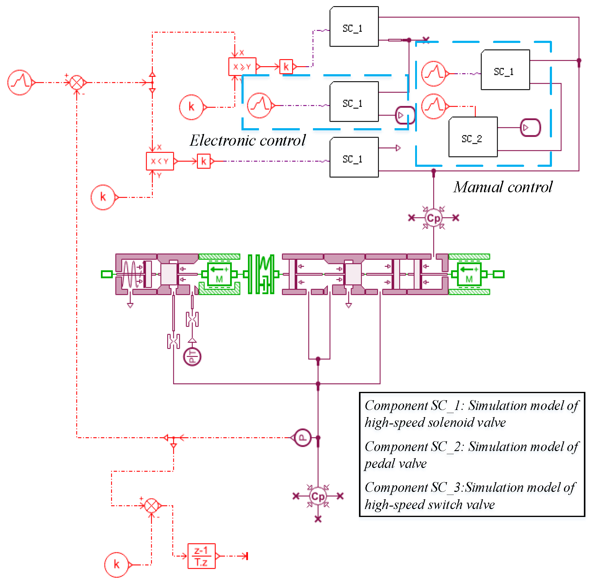
Based on the structural configurations of the APRV, the simulation model is established, and the pressure regulation characteristics are studied. To study all the structural configurations shown in
Figure 2 in one simulation model, the AMESim simulation models of high-speed solenoid valves (Components SC_1 and SC_3,) and pedal valve (Component SC_2) are established. The simulations for the tests of the manual control mode, electronic control mode, coupled control mode and the switch between the control modes are done by switching the control signals of components SC_1, SC_2 and SC_3. The simulation model for the pressure regulation characteristics of the APRV is shown in
Figure 5.
The main structural parameters of the simulation model for the pressure regulation characteristics of the APRV of the different structural configurations in the ECPBS of commercial vehicles are shown in
Table 5.
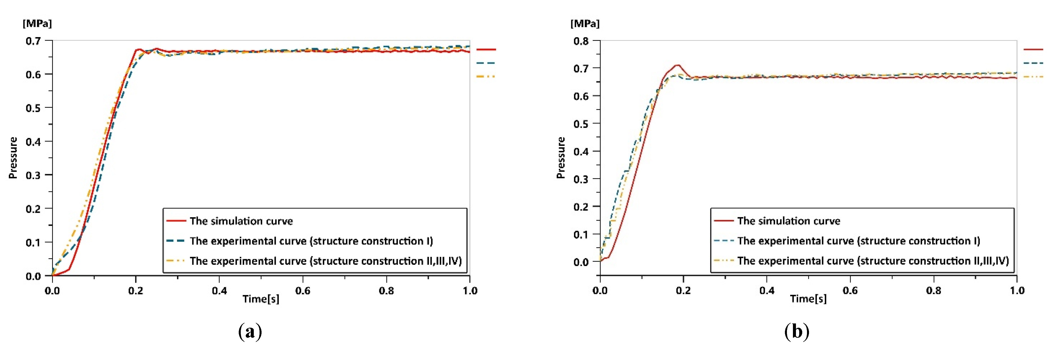
To verify the correctness of the simulation model of the APRV, a series of tests are done on the test bench for the pressure regulation characteristics of the APRV of different structural configurations in the ECPBS of commercial vehicles, and the curves of the pressure regulation characteristics of the pressure regulator under manual control mode and electronic control mode are shown in
Figure 6.
The experiments results and the simulation results show the same trends, similar response times and consistent key values; thus, the simulation model fits well with the test bench. The simulation is done by changing the control signals of components SC_1, SC_2 and SC_3, and the parameters of the simulations for each control condition are shown in
Table 6.
In
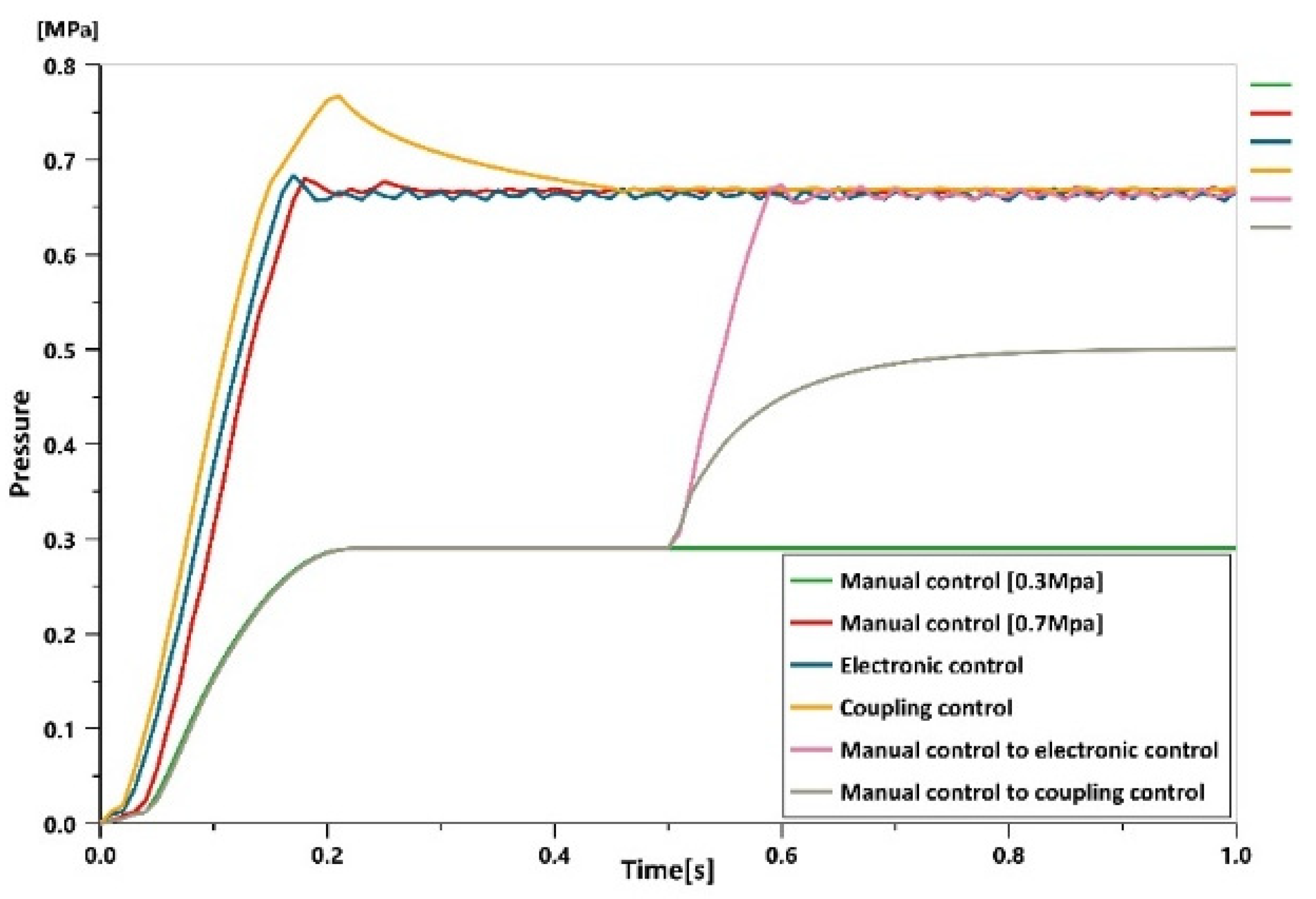
Table 6, the signal value 0 is the deactivation signal, and signal value 1 is the activation signal. It is difficult to simulate the switch from the manual control mode to another mode. To simulate the insufficient pressure during manual-controlled braking, the maximum outlet pressure in the manual control mode is set to 0.3 MPa. In the simulation for the switch test between the control modes, the control mode is switched from the manual control mode to the electronic control mode or coupled control mode in 0.5 s. The simulation results are illustrated in
Figure 7.
In the simulation results, when the control mode switches from the manual control mode to the coupled control mode, the pressure response time increases, and the outlet pressure cannot reach the target level. One possible explanation is that the outlet of the pedal valve is connected to the air tank (electronic control), and the outlet pressure of the pedal valve is higher than the inlet pressure; thus, the air leaks. Compared with switching to the coupled control mode, switching to the electronic control mode avoids such phenomenon, and the pressure response is better. To verify the correctness of the simulation results, the equivalent models for the APRV of the different structural configurations are built to perform tests of the pressure regulation characteristic under different control modes and verify the simulation results.
6. Test-Based Comparative Analysis on the Pressure Regulation Characteristics of the APRV of the Different Structural Configurations in the ECPBS of Commercial Vehicles
According to the performance requirements of the commercial vehicle braking system, the time when the pressure reaches 75% of the target pressure is taken as the index to evaluate the pressure regulation characteristics of the APRV of the different structural configurations under different control conditions.
6.1. Pressurization–Decompression Test under Manual Control
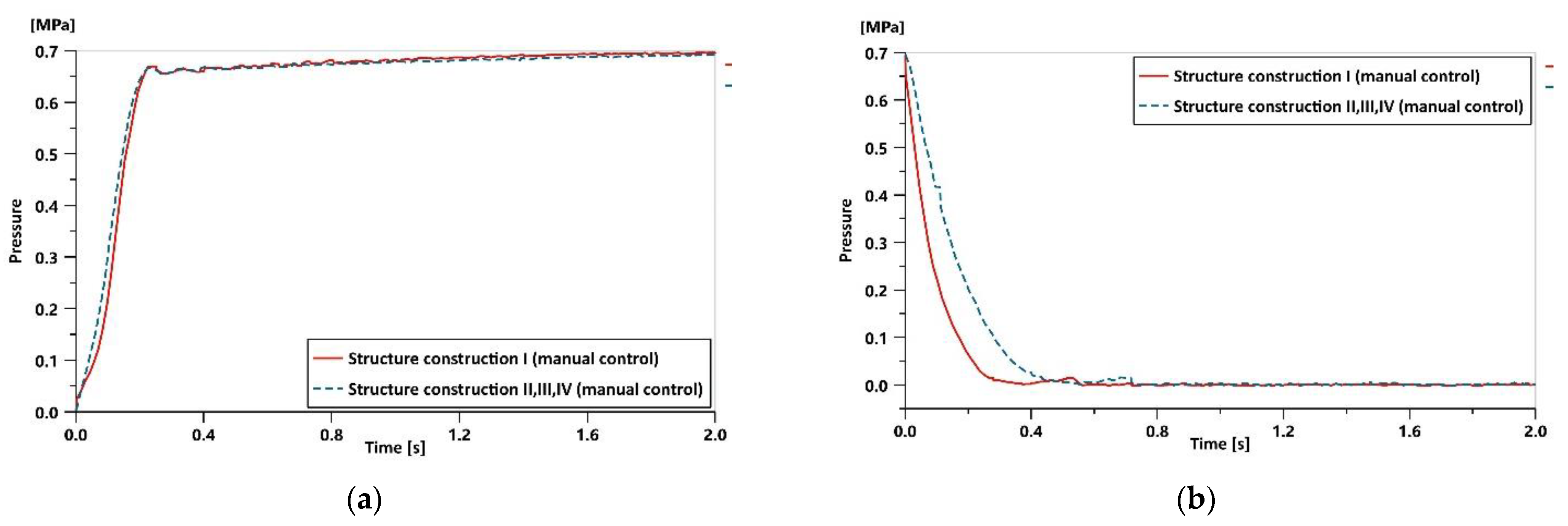
The test results of the pressurization–decompression test of the APRV of the different structural configurations under manual control are illustrated in
Figure 8.
Though there is one more orifice in structural configurations II, III and IV than structural configuration I, all the configurations show no significant difference in the manual-controlled pressurization response, because the volume ratio between the air tank and the control cavity is rather big. The response time for structural configurations II, III and IV to reach 75% of the target pressure is 0.15 s, and response time for structural configuration I to reach that is 0.16 s.
In the manual-controlled decompression test, the control cavity of the APRV exhausts the air to the outer environment, and the pressure in the cavity changes greatly. Limited by the number of orifices, the decompression response time of structural configurations II, III and IV is 0.54 s, and the decompression response time of structural configuration I is 0.38 s. Though the decompression speed of structural configurations II, III and IV is slower, it still meets the requirements of the commercial vehicle braking system.
6.2. Pressurization–Decompression Test under Electronic Control
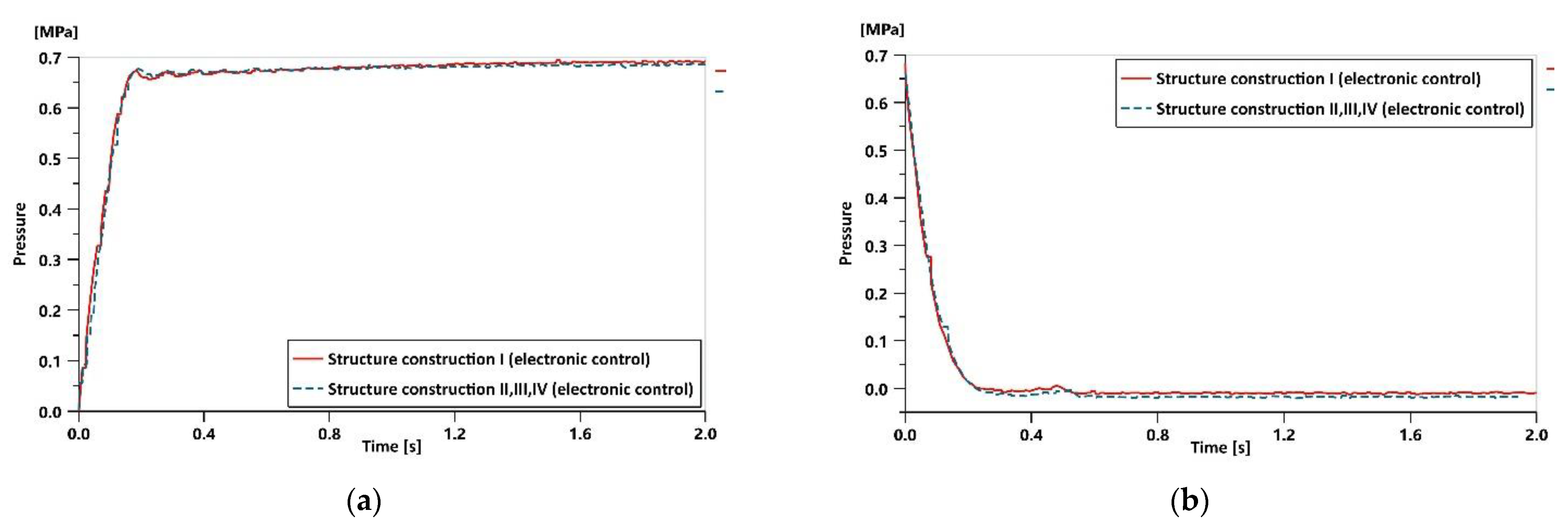
The test results of the pressurization–decompression test of the APRV of the different structural configurations under electronic control are illustrated in
Figure 9.
The response time for structural configurations II, III and IV to reach 75% of the target pressure of 0.7 MPa is 0.13 s, and the response time for structural configuration I to reach that is 0.12 s. Since the working principle of electronic-controlled decompression in all the structural configurations is the same, the decompression response curves fit quite well. The decompression response time of structural configurations II, III and IV is 0.36 s, and the decompression response time of structural configuration I is 0.39 s. Therefore, in the pressurization–decompression test under electronic control, all the structural configurations show no significant differences.
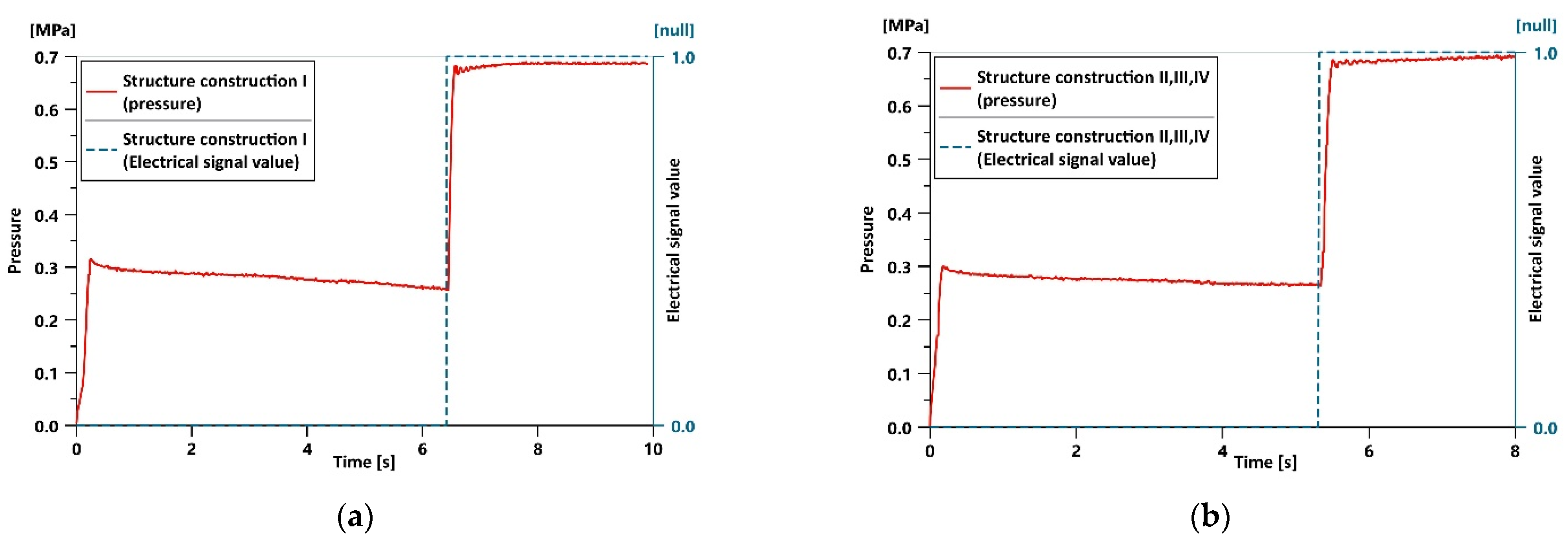
6.3. Switch Test between Manual and Electronic Control Modes during Pressurization
Due to the limitation of the stopping block, the outlet pressure settles at 0.26 MPa in 6.42 s, and the control mode is switched to the electronic control mode, and the pressure increases to 75% of the target pressure of 0.7 MPa in 0.08 s. The test results of the switch test between the manual and electronic control modes during the pressurization of structural configuration I are shown in
Figure 10a.
Due to the limitations of the stopping block, the outlet pressure settles at 0.26 MPa in 5.32 s, and the control mode is switched to the electronic control mode, and the pressure increases to 75% of the target pressure of 0.7 MPa in 0.11 s. The test results of the switch test between the manual and coupled control modes during the pressurization of structural configurations II, III and IV are shown in
Figure 10b.
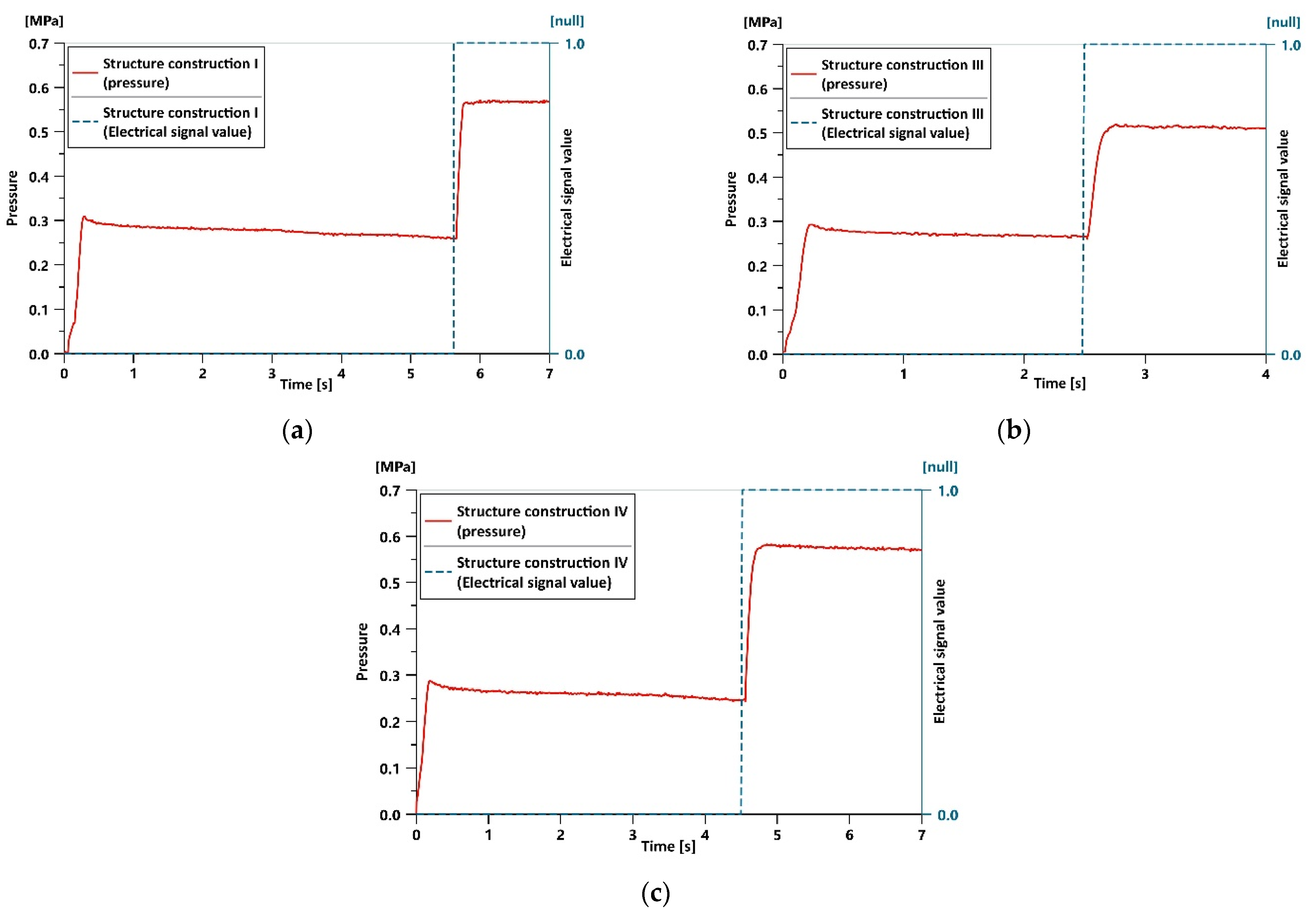
6.4. Switch Test between Manual and Coupled Control Modes during Pressurization
In structural configurations I, III and IV, when the control mode is switched from the manual control mode to the coupled control mode, the control cavity of the APRV, air tank (manual control), air tank (electronic control) and the pedal valve is connected altogether. At this moment, the outlet pressure of the pedal valve is higher than the inlet pressure, so the air from the air tank (electronic control) leaks through the pedal valve continuously, and the pressure of the brake chamber can only reach 0.55 MPa instead of the target pressure of 0.7 MPa. The test results of the switch test between the manual and coupled control modes during pressurization are shown in
Figure 11.
7. Discussion
To investigate the situation in which the driver fails to apply sufficient braking force, simulation and experiment research are done to study the pressure regulation characteristics of the APRV. Combining the simulation and the experiment, the suitable structural configuration is determined, and the theoretical underpinning to develop active safety and driving automation is provided.
Through a comparative analysis, the conclusions are follows:
(1) In the manual-controlled or the electronic-controlled pressurization processes, all structural configurations showed no significant differences. However, in the manual-controlled decompression test, the response time of structural configurations II, III and IV was 42.1% longer than that of structural configuration I. Such a difference is noticeable, but both the results meet the requirements of the braking system.
(2) When the pressure of the electronic control circuit is higher than that of the manual control circuit, leaks happen, and the pressure cannot reach the target value; thus, the driving safety of the vehicle is seriously affected. Since the coupling control mode proposed in this paper has the possibility of air leakage during braking, the APRV in the ECPBS described in this paper cannot use this control mode.
(3) Structural configurations I, III and IV have varying degrees of the possibility of air leakage during braking. Since air leakage during braking in commercial vehicles causes extremely serious accidents, it will lead to an insufficient braking force and be unable to ensure the safety of the vehicle. Therefore, structural configurations II, III and IV are not recommended for use in the ECPBS described in this paper.
In summary, the coupled control mode is not supported in structural configuration II, but the manual control mode and electronic control mode and the switch between these two modes are supported, so the regulation of the braking pressure can be done successfully. Specifically, when the driver cannot apply sufficient braking force, the driving safety of the vehicle can still be guaranteed; thus, the system is consistent with the development of driving automation.
8. Conclusions
The pressure regulating requirements and the control modes of the APRV in the ECPBS of commercial vehicles were proposed, and the structural configurations of the APRV were designed. The simulation model of the control modes of the APRV was established in AMESim; then, the pressure regulation characteristics under different control conditions were analyzed. Specifically, leaks happen when the driver cannot apply sufficient braking force and the control mode is switched from the manual control mode to the coupled control mode, so structural configurations II, III and IV are not recommended for use in the ECPBS described in this paper. The simulation was verified to be correct through experiments on the test bench for the pressure regulation characteristics of the APRVs of different structural configurations. Finally, the best structural configuration was determined, and the theoretical underpinning to improve the driving safety and driving automation was provided.
The driving conditions and driving tasks that were not covered will be studied, and more factors concerning the driver and the environment will be considered in future works to improve the active safety and driving automation. Moreover, new sample products of the APRV will be made and tested. The hardware in the loop test and field test will be tested to gather more experiment data and provide better data and theoretical support.
Author Contributions
Conceptualization, G.L. and H.B.; methodology, H.B. and G.L.; software, H.B., X.W. and Z.W.; validation, G.L. and H.B.; investigation, H.B. and Z.W.; resources, G.L.; data curation, H.B., Z.W. and X.W.; writing—original draft preparation, H.B.; writing—review and editing, H.B., G.L. and Z.W.; visualization, H.B. and G.L.; supervision, G.L.; project administration, G.L. and funding acquisition, G.L. All authors have read and agreed to the published version of the manuscript.
Funding
This research was funded by the China Postdoctoral Science Foundation (2018M642937) and Project 20202h0184, which cooperated with the SMC Corporation.
Institutional Review Board Statement
Not applicable.
Informed Consent Statement
Not applicable.
Data Availability Statement
The study did not report any data.
Acknowledgments
We would like to sincerely thank all our previous and current teachers and classmates who laid the basis for this research, namely Gangyan Li, Jian Hu, Jun Xu, Zaiyu Wang and Xiaoxu Wei.
Conflicts of Interest
The authors declare no conflict of interest.
References
- Ariansyah, D.; Caruso, G.; Ruscio, D.; Bordegoni, M. Analysis of autonomic indexes on drivers’ workload to assess the effect of visual ADAS on user experience and driving performance in different driving conditions. J. Comput. Inf. Sci. Eng. 2018, 18, 031007. [Google Scholar] [CrossRef] [Green Version]
- Chen, H.; Zhao, F.K.; Huang, K.; Tian, Y.T. Driver Behavior Analysis for Advanced Driver Assistance System. In Proceedings of the 2018 IEEE 7th Data Driven Control and Learning Systems Conference, Enshi, China, 25–27 May 2018. [Google Scholar]
- Elizabeth, R.V. Classification and overview of advanced driver assistance systems according to the driving process. In Proceedings of the ASME 2010 International Design Engineering Technical Conferences & Computers and Information in Engineering Conference, Montreal, QC, Canada, 15–18 August 2010. [Google Scholar]
- Edward, S. Analysis of hazards for autonomous driving. J. Auton. Veh. Syst. 2021, 1, 021003. [Google Scholar]
- Giandomenico, C.; Daniele, R.; Dedy, A.; Monica, B. Driving simulator system to evaluate driver’s workload using adas in different driving contexts. In Proceedings of the ASME 2017 International Design Engineering Technical Conferences and Computers and Information in Engineering Conference, Cleveland, OH, USA, 6–9 August 2017. [Google Scholar]
- Bao, H.W.; Wang, Z.Y.; Liu, Z.H.; Li, G.Y. Study on Pressure Change Rate of the Automatic Pressure Regulating Valve in the Electronic-Controlled Pneumatic Braking System of Commercial Vehicle. Processes 2021, 9, 938. [Google Scholar] [CrossRef]
- Wu, S. Design of Function and Structure of Automatic Pressure Regulating Valve for Vehicle Electronically Controlled Air Braking System. Master’s Thesis, Wuhan University of Technology, Wuhan, China, 2019. [Google Scholar]
- Liu, Z.H. Research on Pressure Change Rate of Automatic Pressure Regulating Valve for Commercial Vehicle Electronically Controlled Pneumatic Braking System. Master’s Thesis, Wuhan University of Technology, Wuhan, China, 2020. [Google Scholar]
- Bo, L. Design and Characteristics Analysis of a High Precision Pneumatic Proportional Pressure Valve. Trans. Chin. Soc. Agric. Mach. 2009, 40, 181–187. [Google Scholar]
- Sun, H.; Guan, Z.X. The Electromagnetic Control Air Pressure Brake Valve in the Research and Application of Vehicle Brake System. Appl. Mech. Mater. 2014, 496–500, 1506–1509. [Google Scholar] [CrossRef]
- You, M.; Zhang, J.; Sun, D. Characteristics analysis and control study of a pneumatic proportional valve. In Proceedings of the Advanced Information Technology, Electronic and Automation Control Conference, Chongqing, China, 19–20 December 2015. [Google Scholar]
- Cazzola, G.J.; Arias, R.E.; Mirassou, H.M. Influence of the Relay Valve on Pneumatic Brake Systems. DYNA 2017, 92, 661–666. [Google Scholar] [CrossRef]
- Zhao, J.H.; Shi, Y.; Grekhov, L.; Ma, X.Z. Effects of structure parameters on the static electromagnetic characteristics of high speed solenoid valves. Int. J. Appl. Electromagn. Mech. 2017, 55, 45–60. [Google Scholar] [CrossRef]
- Hu, D.W.; Li, G.Y.; Deng, F. Gain-Scheduled Model Predictive Control for a Commercial Vehicle Air Brake System. Processes 2021, 9, 899. [Google Scholar] [CrossRef]
- Hu, D.W.; Li, G.Y.; Zhu, G.M.; Liu, Z.H.; Wang, Y.X. A Control-Oriented Linear Parameter-Varying Model of a Commercial Vehicle Air Brake System. Appl. Sci. 2020, 10, 4589. [Google Scholar] [CrossRef]
- Hu, D.W.; Li, G.Y.; Zhu, G.M.; Liu, Z.H.; Tu, M. Linear-Quadratic Tracking Control of a Commercial Vehicle Air Brake System. IEEE Access 2020, 8, 149741–149750. [Google Scholar] [CrossRef]
- Zhang, B.; Zhong, Q.; Ma, J.E.; Hong, H.C.; Bao, H.M.; Shi, Y.; Yang, H.Y. Self-correcting PWM control for dynamic performance preservation in high speed on/off valve. Mechatronics 2018, 55, 141–150. [Google Scholar] [CrossRef]
- Sorli, M.; Figliolini, G.; Pastorelli, S. Dynamic Model and Experimental Investigation of a Pneumatic Proportional Pressure Valve. Mechatron. IEEE/ASME Trans. Mechatron. 2004, 9, 78–86. [Google Scholar] [CrossRef]
- Han, J.C.; Zhao, W.Q.; Zong, C.F. Simulation and HIL Test for Proportional Relay Valve of Commercial Vehicle Pneumatic EBS. Appl. Mech. Mater. 2013, 437, 418–422. [Google Scholar] [CrossRef]
- Han, J.C.; Zhao, W.Q.; Zong, C.F. Research on Characteristics of Proportional Relay Valve for Commercial Vehicle Pneumatic EBS. SAE Tech. Pap. 2013. [Google Scholar] [CrossRef]
- Miller, J.I.; Flack, T.J.; Cebon, D. Modeling the Magnetic Performance of a Fast Pneumatic Brake Actuator. J. Dyn. Syst. Meas. Control-Trans. ASME 2014, 136, 021022. [Google Scholar] [CrossRef]
- Li, P.X.; Su, M.; Zhang, D.B. Response characteristic of high-speed on/off valve with double voltage driving circuit. IOP Conf. Ser. Mater. Sci. Eng. 2017, 220, 012–028. [Google Scholar] [CrossRef] [Green Version]
- Su, M.; Liu, Y.G.; Yang, H.T. Study on Adaptive Dual-Voltage Method to Improve the Control Performance of High-Speed Solenoid Valve. Appl. Mech. Mater. 2012, 220–223, 615–621. [Google Scholar] [CrossRef]
- Lee, I.Y. Switching response improvement of a high speed on/off solenoid valve by using a 3 power source type valve driving circuit. In Proceedings of the IEEE 2006 IEEE International Conference on Industrial Technology, Mumbai, India, 15–17 December 2006. [Google Scholar]
- Yang, F. Study on Pneumatic Characteristics Calculation Method of the Fundamental Components of Air Brake Circuit for Intelligence Braking. Ph.D. Thesis, Wuhan University of Technology, Wuhan, China, 2018. [Google Scholar]
Figure 1.
Principle drawing of the ECPBS in commercial vehicles.
Figure 1.
Principle drawing of the ECPBS in commercial vehicles.
Figure 2.
Principle drawing of the different structural configurations of the APRV.
Figure 2.
Principle drawing of the different structural configurations of the APRV.
Figure 3.
Test bench for the pressure regulation characteristics of the APRV of different structural configurations.
Figure 3.
Test bench for the pressure regulation characteristics of the APRV of different structural configurations.
Figure 4.
Software interface of the test bench for the pressure regulation characteristics of the APRV of different structural configurations in the ECPBS of commercial vehicles.
Figure 4.
Software interface of the test bench for the pressure regulation characteristics of the APRV of different structural configurations in the ECPBS of commercial vehicles.
Figure 5.
Simulation model for the pressure regulation characteristics of the APRV of the different structural configurations in the ECPBS of commercial vehicles.
Figure 5.
Simulation model for the pressure regulation characteristics of the APRV of the different structural configurations in the ECPBS of commercial vehicles.
Figure 6.
Verification of the simulation model for the pressure regulation characteristics of the APRV of the different structural configurations in the ECPBS of commercial vehicles: (a) manual control and (b) electronic control.
Figure 6.
Verification of the simulation model for the pressure regulation characteristics of the APRV of the different structural configurations in the ECPBS of commercial vehicles: (a) manual control and (b) electronic control.
Figure 7.
Simulation curves of the pressure regulation characteristics of the APRV of the different structural configurations in the ECPBS of commercial vehicles.
Figure 7.
Simulation curves of the pressure regulation characteristics of the APRV of the different structural configurations in the ECPBS of commercial vehicles.
Figure 8.
Test results of the pressurization–decompression test under manual control: (a) pressurization test and (b) decompression test.
Figure 8.
Test results of the pressurization–decompression test under manual control: (a) pressurization test and (b) decompression test.
Figure 9.
Test results of the pressurization–decompression test under electronic control: (a) pressurization test and (b) decompression test.
Figure 9.
Test results of the pressurization–decompression test under electronic control: (a) pressurization test and (b) decompression test.
Figure 10.
Results of the switch test between the manual control mode and electronic control mode during pressurization: (a) structural configuration I and (b) structural configurations II, III and IV.
Figure 10.
Results of the switch test between the manual control mode and electronic control mode during pressurization: (a) structural configuration I and (b) structural configurations II, III and IV.
Figure 11.
Results of the switch test between the manual and coupled control modes during pressurization: (a) structural configuration I, (b) structural configuration III and (c) structural configuration IV.
Figure 11.
Results of the switch test between the manual and coupled control modes during pressurization: (a) structural configuration I, (b) structural configuration III and (c) structural configuration IV.
Table 1.
Features of the different structural configurations of the APRV.
Table 1.
Features of the different structural configurations of the APRV.
| Structural Configuration | High-Speed Switch Valve | High-Speed Inlet/Exhaust Valve | Support for Manual Control Mode | Support for Electronic Control Mode | Support for Coupled Control Mode |
|---|
| I | Not available | 1 NO and 2 NCs | Yes | Yes | Yes |
| II | two-position three-way solenoid valve | 1 NO and 1 NC | Yes | Yes | No |
| III | three-position three-way solenoid valve | 1 NO and 1 NC | Yes | Yes | Yes |
| IV | two-position three-way solenoid valve | 1 NO and 2 NCs | Yes | Yes | Yes |
Table 2.
Control conditions for the test of the pressure regulation characteristics of the APRV in structural configuration I.
Table 2.
Control conditions for the test of the pressure regulation characteristics of the APRV in structural configuration I.
| Structural Configuration | Control Condition | Pedal Valve | High-Speed Inlet Valve 1 | High-Speed Exhaust Valve | High-Speed Inlet Valve 2 |
|---|
| Configuration I | Pressurization−decompression test under manual control | Fully open → release | Deactivated | Deactivated | Deactivated |
| Pressurization−decompression test under electronic control | Release | Activated → deactivated | Deactivated → activated | Activated |
| Switch test between manual and electronic control modes during pressurization | Driven to the fixed point | Deactivated → activated | Deactivated | Deactivated → activated |
| Switch test between manual and coupled control modes during pressurization | Driven to the fixed point | Deactivated → activated | Deactivated | Deactivated |
Table 3.
Control conditions for the test of the pressure regulation characteristics of the APRV in structural configurations II, III and IV.
Table 3.
Control conditions for the test of the pressure regulation characteristics of the APRV in structural configurations II, III and IV.
| Structural Configuration | Control Condition | Pedal Valve | High-Speed Switch Valve | High-Speed Inlet Valve (Normally Open) | High-Speed Exhaust Valve | High-Speed Inlet Valve |
|---|
| Structural configuration II, III, IV | Pressurization−decompression test under manual control | Fully open → release | Deactivated | Deactivated | Deactivated | Deactivated |
| Pressurization−decompression test under electronic control | Release | Activated | Deactivated → activated | Deactivated → activated | Deactivated |
| Switch test between manual and electronic control modes during pressurization | Driven to the fixed point | Deactivated → activated | Deactivated | Deactivated | Deactivated |
| Structural configuration IV | Switch test between manual and coupled control modes during pressurization | Driven to the fixed point | Deactivated | Deactivated | Deactivated | Deactivated → activated |
Table 4.
Control conditions for the test of the pressure regulation characteristics of the APRV in structural configuration III.
Table 4.
Control conditions for the test of the pressure regulation characteristics of the APRV in structural configuration III.
| Structural Configuration | Control Condition | Pedal Valve | High-Speed Switch Valve | High-Speed Inlet Valve 1 (Normally Open) | High-Speed Exhaust Valve | High-Speed Inlet Valve 2 |
|---|
| Structural configuration III | Switch test between manual control mode and electronic control mode during pressurization | Driven to the fixed point | Deactivated | Deactivated | Deactivated | Deactivated → activated |
Table 5.
Main structural parameters of the simulation model for the pressure regulation characteristics of the APRV of different structural configurations in the ECPBS of commercial vehicles.
Table 5.
Main structural parameters of the simulation model for the pressure regulation characteristics of the APRV of different structural configurations in the ECPBS of commercial vehicles.
| Parameter | Air Source Pressure | Seal-Ring Diameter | Hole Diameter | Volume of Control Cavity | Maximum Travel |
|---|
| Values | 0.7 MPa | 7 mm | 6 mm | 0.04 L | 0.24 mm |
| Parameter | Number of coil turns | Winding resistance | Spring rate | Preload force | Mass of the valve core |
| Values | 1000 | 50 Ohm | 2000 N/m | 10 N | 5 g |
Table 6.
Parameters of the simulation models for the pressure regulation characteristics of the APRV of the different structural configurations in the ECPBS of commercial vehicles.
Table 6.
Parameters of the simulation models for the pressure regulation characteristics of the APRV of the different structural configurations in the ECPBS of commercial vehicles.
| | Parameter | Signal Source (SC_1) | Signal Source (SC_2) | Signal Source (SC_3) | Pressure of Air Tank (Electronic Control) | Pressure of Air Tank (Manual Control) | Structural Configuration |
|---|
| Control Condition | |
|---|
| Electronic control | 1 | 0 | 0 | 0.7 MPa | 0 | All structural configuration |
| Manual control (0.3 MPa) | 0 | 1 | 1 | 0 | 0.3 MPa |
| Manual control (0.7 MPa) | 0 | 1 | 1 | 0 | 0.7 MPa |
| Coupled control | 1 | 1 | 1 | 0.7 MPa | 0.7 MPa | Structural configuration
I, III, IV |
| Switch between manual and electronic control modes | 0–0.5 s: 0 | 0–0.5 s: 1 | 0–0.5 s: 1 | 0.7 MPa | 0.3 MPa |
| 0.5–1 s: 1 | 0.5–1 s: 0 | 0.5–1 s: 0 |
| Switch between manual and coupled control modes | 0–0.5 s: 0 | 0–0.5 s: 0 | 0–0.5 s: 0 | 0.7 MPa | 0.3 MPa |
| 0.5–1 s: 1 | 0.5–1 s: 1 | 0.5–1 s: 1 |
| Publisher’s Note: MDPI stays neutral with regard to jurisdictional claims in published maps and institutional affiliations. |
© 2021 by the authors. Licensee MDPI, Basel, Switzerland. This article is an open access article distributed under the terms and conditions of the Creative Commons Attribution (CC BY) license (https://creativecommons.org/licenses/by/4.0/).


