1. Introduction
In recent years, bike riding has become a popular leisure sport around the world. For this reason, analysts forecast that the global high-end bicycle market will grow with a compound annual growth rate (CAGR) of 4.82% during the period 2017–2021 according to the report from Research and Markets Ltd. It is known that high-end bikes demand a high quality of bike frame [
1,
2,
3,
4,
5,
6,
7]. Unfortunately, frame QC still relies on the Vernier caliper, the plug gauge, the cylindrical gauge, and the thread gauge, etc. It normally takes a long time to complete the process. Consequently, the automation measurement process for the QC of the bike frame is essential in industry [
8,
9,
10,
11,
12].
The coordinate-measuring-machine (CMM) is now being widely applied as part of workpiece inspection in the production line [
13,
14,
15,
16,
17]. It can be used to measure the geometry of physical objects by sensing the discrete points on the object surface with a probe, including mechanical, optical, laser, and white light. Basically, it has two major advantages: (1) high precision up to 0.001 mm and (2) high reliability in both hardware and software. However, the CMM inspection planning session has been a challenging issue because of its time-consuming nature using traditional methods, e.g., expert experiences and technical documents data mining. Additionally, it may suffer from some following disadvantages: (1) Its operation speed is limited. (2) It is sensitive to the environment temperature and humidity. (3) It is not applicable to irregular shape object measurements. (4) It has a high cost. Obviously, CMM is not suitable for the bike frame measurement due to the restriction of the operation range. Alternatively, robotic arms are typically used for multiple industrial applications such as material handling, welding, thermal spraying, assembly, palletizing, drilling, and painting, etc. [
18,
19,
20,
21]. For instance, a platform based on a robotic arm using three degrees of freedom (DoF) principle was proposed to estimate the calibration parameters of microelectromechanical systems (MEMS) [
22]. It can be placed indifferent positions for collecting a dataset of points evenly distributed. This case implies that the measurement technique using robotic arms may provide a good solution for the bike frame QC process.
2. System Description
2.1. System Structure
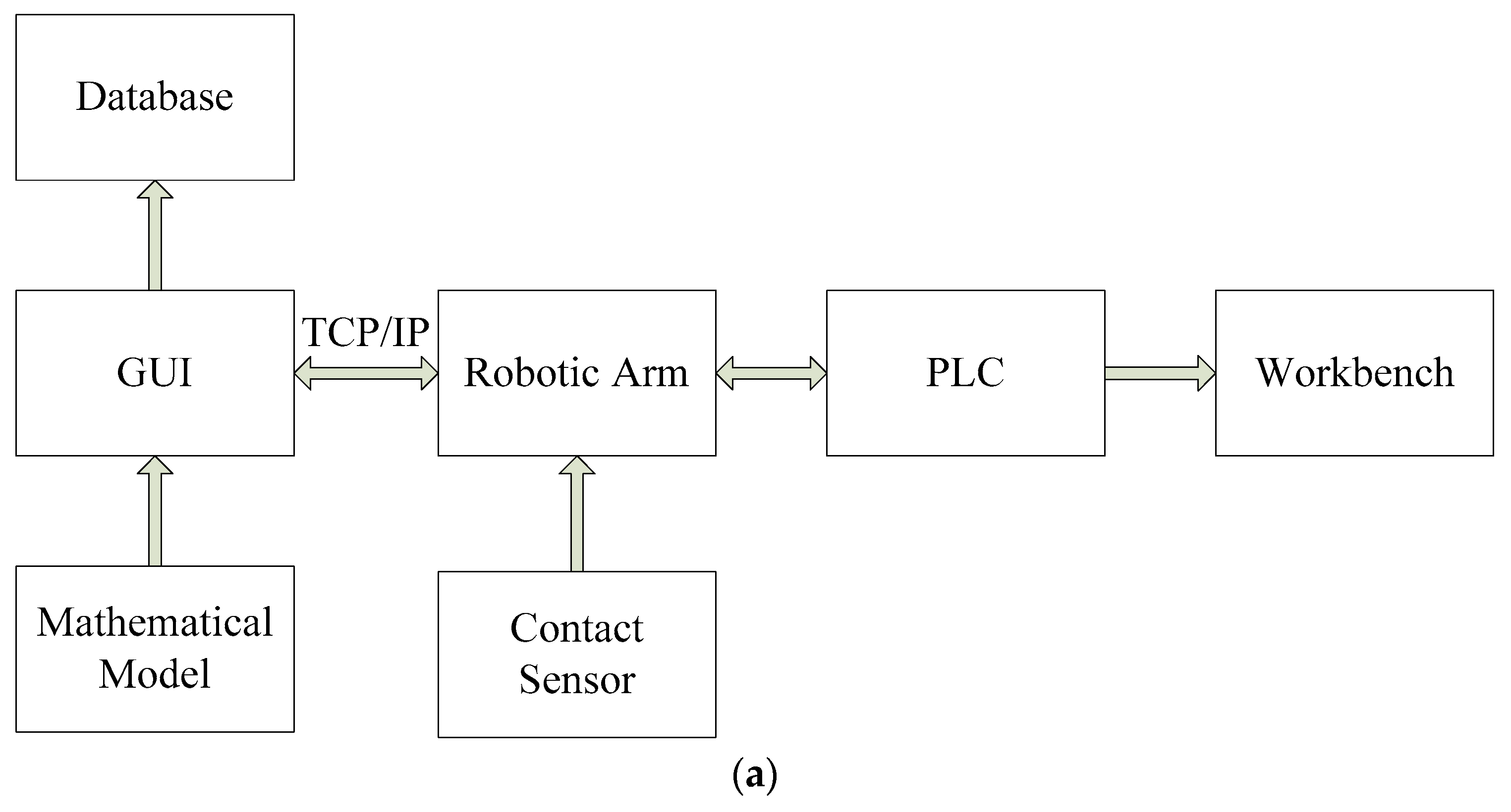
The proposed system structure of bike frame quality check is shown in
Figure 1a, consisting of subsystems such as robotic arm, graphical user interface (GUI), programmable logic controller (PLC), contact sensor, mathematical model, database, and workbench. Each subsystem is responsible to carry out a specific task, described as follows. (1) Robotic arm can carry the contact sensor and move it to the check points. Therefore, the coordinates of check points can be found based on the robotic arm coordinate system. (2) The contact sensor can feedback a digital signal to the robotic arm immediately once it touches the surface of the check points. (3) PLC is to control the rotating disk to rotate the bike frame
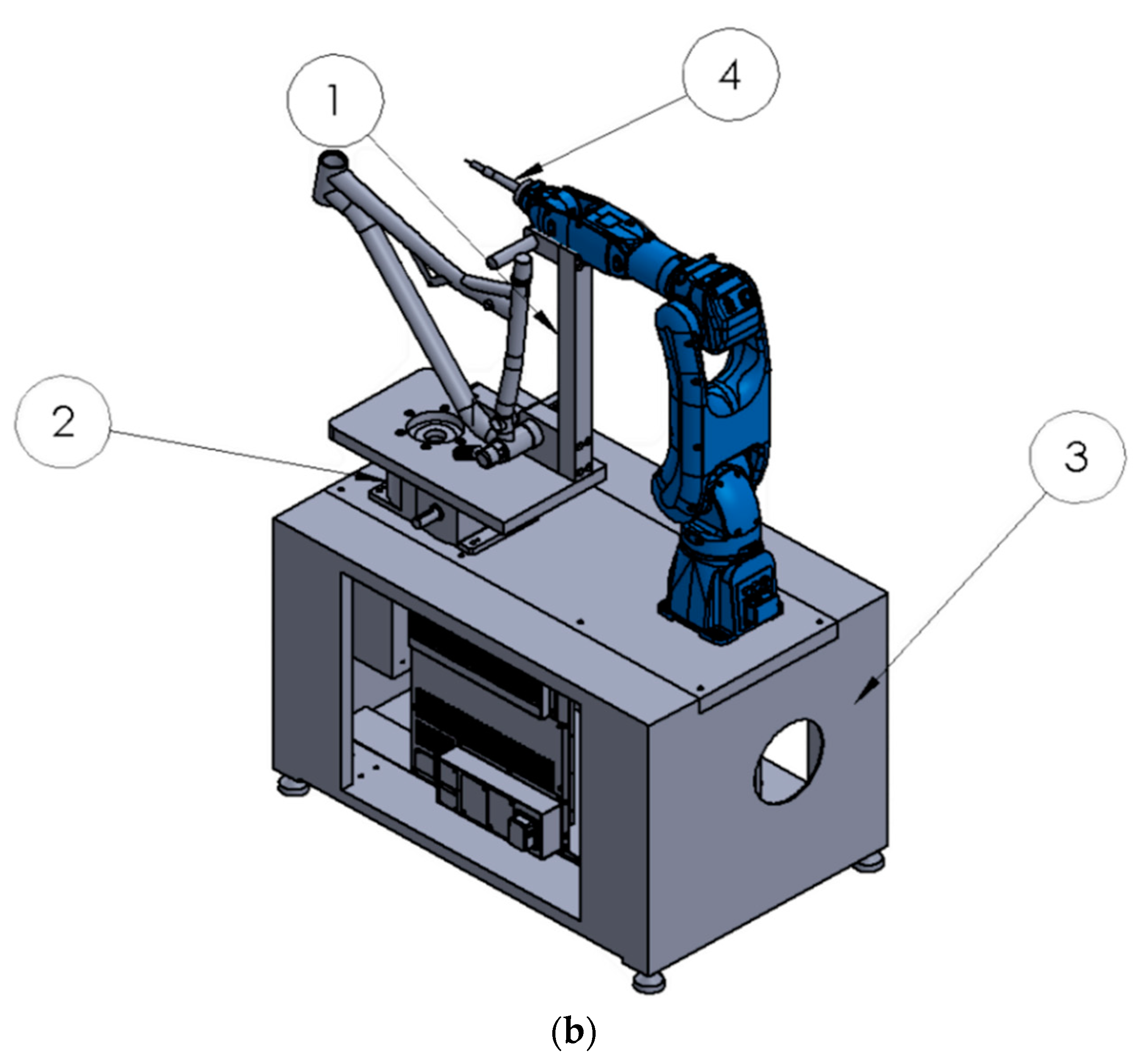
for the robotic arm to reach every check point. (4) Graphical user interface (GUI) provides a friendly user interface for users to input data and display a real-time measurement outcome. (5) Mathematical model presents a geometry algorithm that can effectively integrate the sphere formula with the inner product of normal vector to find four parameters in the sphere formula using only three measured points. Accordingly, the center coordinate of check point and its diameter can be calculated accurately and simply. (6) A database using MySQL is used to store the measured data and export measurement data report. (7) The workbench shown in
Figure 1b is designed to sustain all hardware devices. It contains: (1) a fixing frame, (2) A rotating disk, (3) a work platform, and (4) a sensor pedestal. Moreover, the XAML and C# package are used to build up the system software such as the robotic arm simulation object, the window object, the control object, and the 3D-geometry mathematical model. Through Transmission Control Protocol (TCP) and Internet Protocol (IP) (TCP/IP), the contact sensor and robotic arm can communicate with each other between different objects.
In this study, we mainly focused on the development of mathematical model required for the bike frame quality check using a robotic arm. Based on the proposed mathematical model, the robotic arm is combined with the contact sensor to implement the bike frame quality check in shaft length, internal diameter, verticality, and parallelism, etc. The major devices used in the proposed system are listed as follows:
- (1)
Robotic arm: YASKAWA-GP7
- (2)
Contact sensor: Compact module changing touch-trigger probe (Renishaw TP20)
- (3)
PLC: DELTA DVP –PM1000M
- (4)
Database: MySQL
2.2. Introduction of Bike Frame
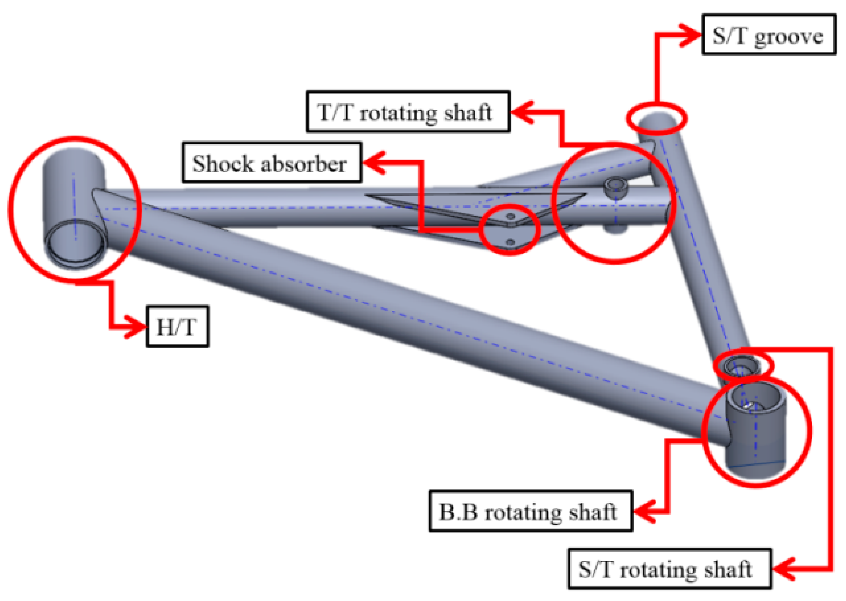
Generally, the bike frame consists of: (1) a B.B rotating shaft, (2) a S/T rotating shaft, (3) a S/T groove, (4) a T/T rotating shaft, (5) a shock absorber, (6) and H/T, where they are required for quality check, as shown in
Figure 2.
3. Mathematical Model
The check items of bike frame for quality evaluation mainly include the shaft length, internal diameter, verticality, and parallelism located in different shafts. The proposed mathematical model provides the solutions for checked point coordinate calculation. It is described as follows.
3.1. Generation of Bike Frame Center Plane
Initially, the center plane of a bike frame should be generated from the B.B rotating shaft, as shown in
Figure 3, which is used as the base of the coordinate system. The coordinate of the center point
, as shown in
Figure 3, can be determined from
and
as:
| | |
3.2. Center Plane Offset
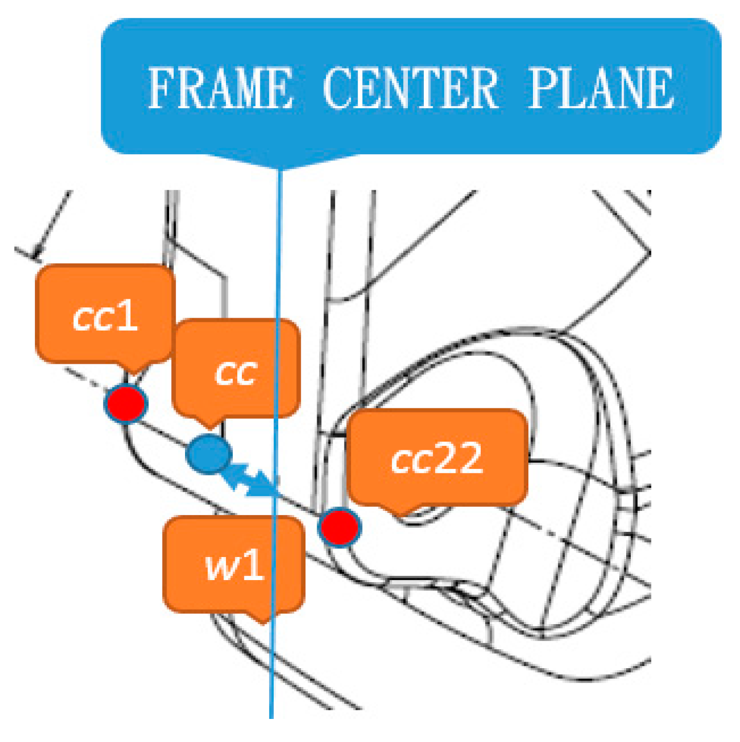
The center plane offset is used to check if there is a shift at the center plane. For this purpose, the y-axis taken from the center point is regarded as the center standard plane.
In
Figure 4, two check points, i.e.,
cc1 and
cc22, coordinates at the S/T rotating shaft are expressed as:
| |
cc is defined as the center point between
cc1 and
cc22 as:
w1 shown in Equation (1) is defined as the center plane offset at the S/T rotating shaft, and it is the distance between the y axis coordinate of the
cc point and the center plane.
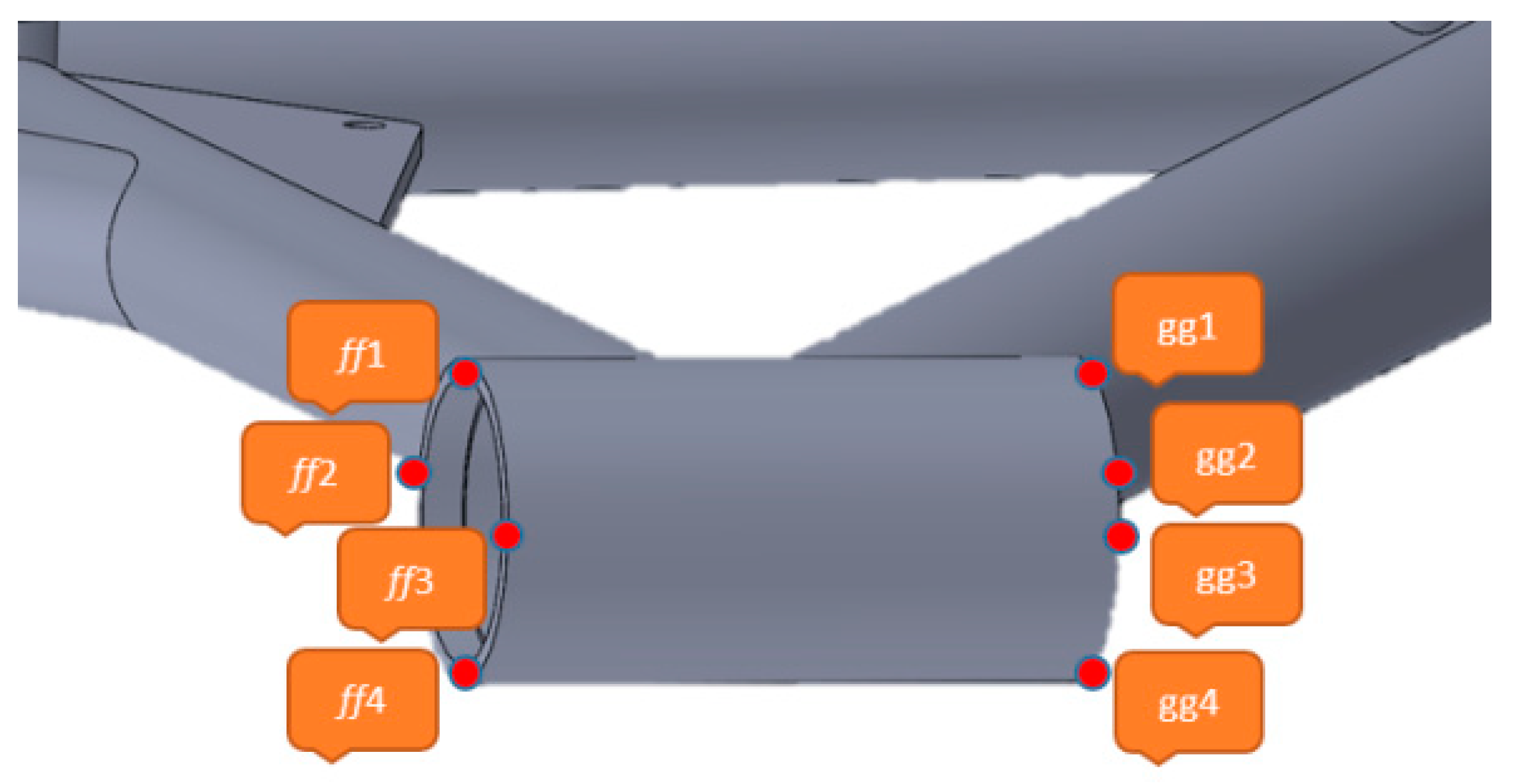
3.2.1. H/T Rotating Shaft Length
The H/T rotating shaft length can be determined by taking eight check points, as shown in
Figure 5.
The coordinates of the eight check points are shown as follows:
| | | |
| | | |
The length
between two check points (
and
) is:
Similarly, the lengths , , and can be formulated according to Equation (2), where the number one changes to numbers two to four, respectively.
Average length (L) between two check points (
and
) is:
3.2.2. T/T Rotating Shaft Internal Diameter
The three check points at the T/T rotating shaft can be used to calculate the internal diameter, as shown in
Figure 6.
The coordinates of the three check points are expressed as:
| | |
The vectors
and
are:
The use cross product for the vectors
and
, and their normal vector
can be obtained as:
where
The spherical general shown in Equation (7) is used to find the axis point coordinate and axial bore radius in
Figure 6:
where the spherical axis point coordinate (
d4) in
Figure 6 is
, and
d,
e,
f, and
g are real numbers.
The vector
can be obtained as:
The vectors
and
are perpendicular to each other so that their inner product is zero.
Following this, we substitute the coordinates of three check points
,
,
into Equation (7) to form Equations (10)–(12). Additionally, Equation (13) is obtained based on Equation (9).
The parameters values (d, e, f, g) can be thus be found by solving the simultaneous equations from Equations (10)–(13).
Consequently,
can be obtained, and the axial bore radius of T/T rotating shaft can be calculated as:
3.2.3. Parallelism
In
Figure 7, the parallelism angle between B.B. and T/T rotating shafts can be calculated as follows:
Using the inner product formula, the parallelism angel
between
and
can be calculated as:
3.2.4. Verticality
In
Figure 8, the verticality angel between B.B. and H/T rotating shafts can be calculated as follows.
Use the inner product formula, the verticality angel
between
and
can be calculated as:
4. Model Verification Using the Real Data
The proposed mathematical model is verified using the real data taken from the SOLIDWORKS drawing of the bike frame.
4.1. The Center Plane
From
Figure 3, the two check points are:
| |
The center point of B.B rotating shaft is
, where:
|
|
|
|
Accordingly, the center plane is located at
4.2. Bike Center Plane Offset
From
Figure 4, it is known that:
| |
The is located at the center point between and .
Therefore,
|
|
As above, it is confirmed that the theoretical value matches the computational result.
4.3. The H/T Rotating ShaftLength
In
Figure 5, the coordinates of eight check points are shown as follows.
| | |
| | |
| | |
Accordingly,
|
|
|
|
The average length (L) is obtained as:
As above, the calculated value is confirmed equal to the theoretical value.
4.4. T/T Rotating Shaft Internal Diameter
In
Figure 6, the coordinates of three check points (
d1,
d2,
d3) are shown as follows:
| | |
Therefore,
where;
|
|
|
|
According to Equation (7), the axis point coordinate is .
and
are perpendicular to each other so that:
⇒
Substitute the coordinates of
d1,
d2 and
d3 into Equation (10), as follows.
⇒
| | |
As above, it can be obtained:
|
The radius between the axis and check point is:
Accordingly, the internal diameter of T/T rotating shaft is:
|
As above, the calculated value is confirmed equal to the theoretical value.
4.5. Parallelism Between T/T and B.B Rotating Shafts Axes
In
Figure 8, the coordinates of two check points (
d1,
d11) are:
| |
The coordinate of middle point
d5 located between
d1 and
d2 is:
The X-axis and Y-axis coordinates of axis point
d4 at the T/T rotating shaft are transferred to d5 to form
. Therefore, the vector formed by
d4 and
is
.
In
Figure 7,
| |
at the B.B rotating shaft is:
The parallelism angel (
) between
and
can be calculated as:
As above, the T/T and B.B rotating shafts axes are confirmed parallel.
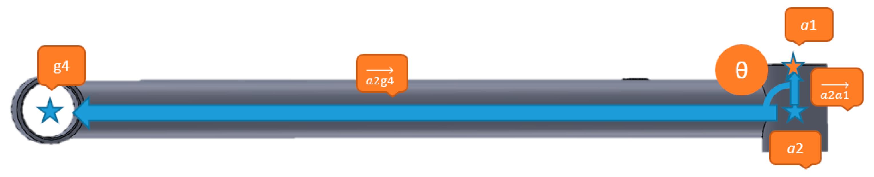
4.6. Verticality Between H/T and B.B Rotating Shafts Axes
The vector
from the B.B rotating shaft to H/T axis point (g4) is:
|
where
and
.
The verticality angel (
) between
and
can be calculated as:
As above, the H/T and B.B rotating shafts axes are confirmed vertical.
5. Practical Verification
The process of real bike frame quality check is carried out based on the proposed 3D geometry mathematical model. The real system profile is shown in
Figure 9.
5.1. Results with GUI
5.1.1. Bike Frame Plane
The GUI of the bike frame plane is shown in
Figure 10. The performance result is –333.5 mm and that matches the theoretical value.
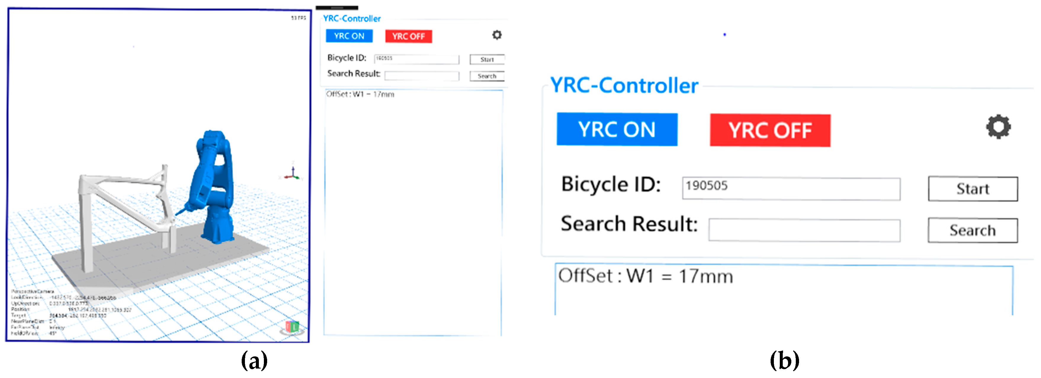
5.1.2. Bike Center Plane Offset
The GUI of bike center plane offset is shown in
Figure 11. The performance result is 17 mm and that matches the theoretical value.
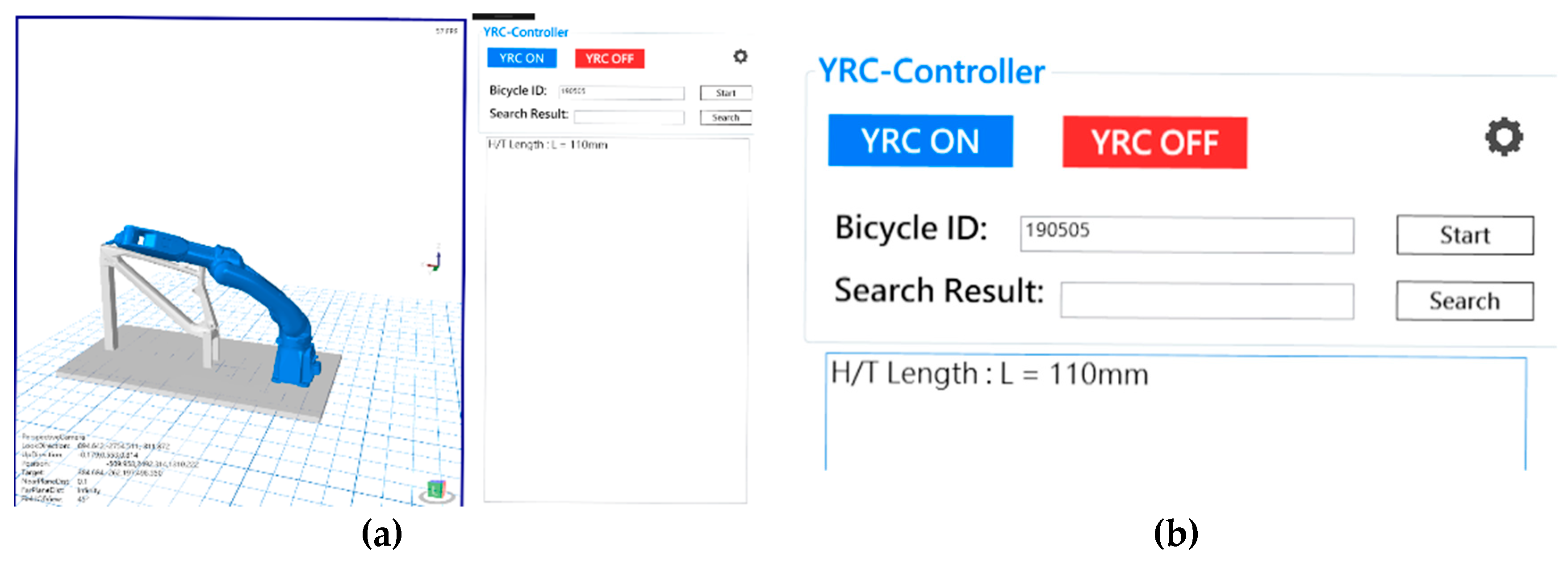
5.1.3. H/T Rotating Shaft Length
The GUI of H/T rotating shaft length is shown in
Figure 12. The performance result is 110 mm and that matches the theoretical value.
5.1.4. T/T Rotating Shaft Internal Diameter
The GUI of T/T rotating shaft internal diameter is shown in
Figure 13. The performance result is 15 mm and that matches the theoretical value.
5.1.5. Parallelism
The parallelism between T/T and B.B rotating shafts axes using GUI is shown in
Figure 14. The performance result is
that matches the theoretical value.
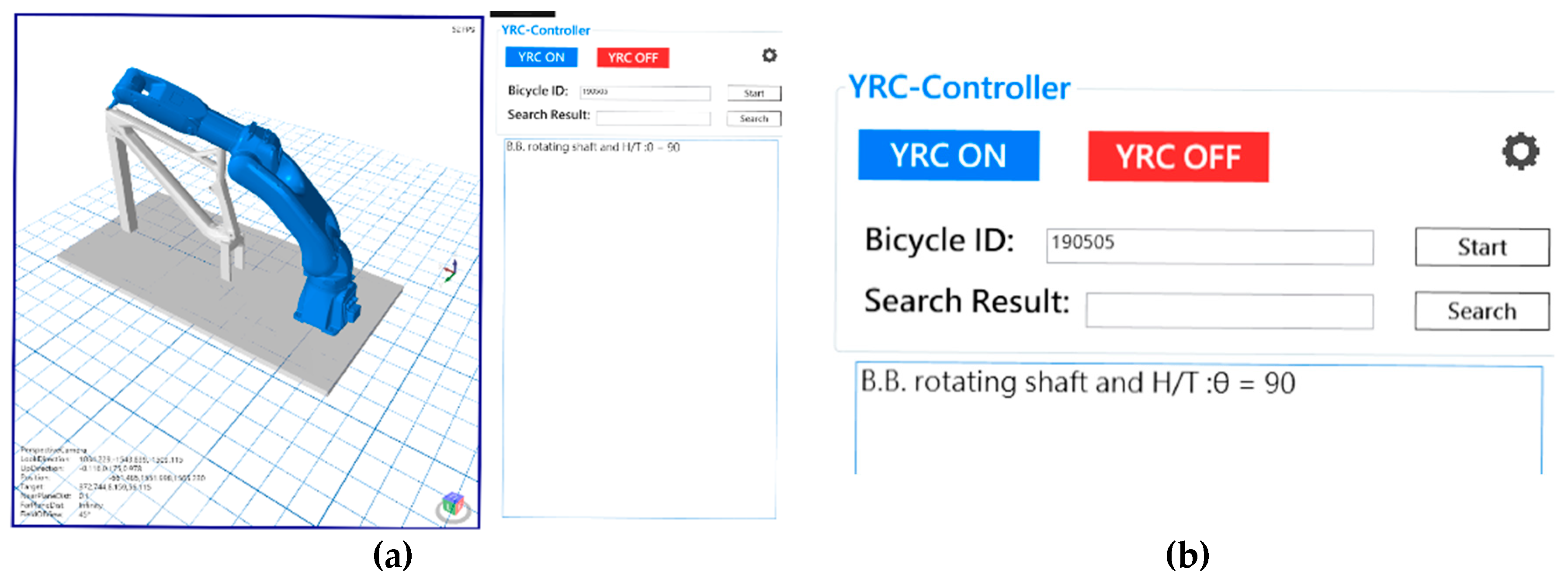
5.1.6. Verticality
The verticality between H/T and B.B rotating shafts axes using GUI is shown in
Figure 15. The performance result is
that matches the theoretical value.
5.2. Practical Results
The measurement results from 10-times average values using the real bike frame are concluded in
Table 1. Based on the same bike frame, the error between the proposed model and the Vernier caliper is below 0.05 mm, and the repeatability is at the range of 0.1 mm. This verifies that the proposed model presents both robust and stable performance. Nevertheless, the measured data reveals that the tested frame has some defects occurred in the center plane offset, parallelism and verticality.
To clarify the uncertainty of the measurement, the estimated standard deviation for a series of
n measurements is expressed mathematically as:
where
is the result of the
measurement and
is the arithmetic mean of the
n measurement results.
When a set of several repeated readings has been taken, the mean,
, and estimated standard deviation,
s, can be calculated. The measurement uncertainty,
u, of the mean is therefore defined as:
where
n is the number of measurements in the set.
The estimated standard deviation and measurement uncertainty based on 10 measurements for S/T rotating shaft, T/T rotating shaft, and H/T rotating shaft is shown in
Table 2,
Table 3 and
Table 4, respectively. From the statistics, it is obvious that both standard deviation (
s) and measurement uncertainty (
u) for all shaft measurements present a very low value no more than 0.018. Thus, accuracy and robustness of the proposed model is thus confirmed.
6. Conclusions
Traditional methods for the QC of bike frame products usually use general jigs or Vernier calipers. However, this kind of measurement process may take tens of minutes to complete. Another disadvantage is that it is difficult to analyze the measured data due to lack of computerization. For these reasons, the proposed 3D geometry mathematical model has successfully developed an accurate bike frame measurement based on a robotic arm with a contact sensor. In this study, the proposed model requires only three simultaneous equations to find the axis coordinate and its radius instead of four equations in a space sphere. It verifies that the measured data obtained from the model performance is consistent with the SOLIDWORKS drawing, including H/T rotating shaft length, T/T rotating shaft internal diameter, parallelism, and verticality, etc. Accordingly, it is applicable for industrial QC applications in a variety of bike frames. Other than these advantages, the stylus probe used in this proposed model presents both simple and accurate performance. However, successful measurement depends on the activity range of robotic arm that the certain features of bike frames should be reached by the stylus probe. In the future work, the optical sensors used in CMM may provide an alternative solution, although more complex signal processing algorithm should be addressed.
Author Contributions
All authors conceived the study. H.-C.L. led the project and wrote this article. B.-R.Y. built the mathematical model. J.-Y.W. (Jen-Yu Wang) designed the system software. J.-Z.L. wrote the robotic-arm control program. J.-Y.W. (Jia-Yang Wu) designed the system mechanism.
Funding
This work was supported by the Ministry of Science and Technology, Taiwan (grant number MOST 108-2637-E-167-001).
Conflicts of Interest
The authors declare no conflict of interest.
References
- Cicero, S.; Lacalle, R.; Cicero, R.; Fernández, D.; Méndez, D. Analysis of the cracking causes in an aluminium alloy bike frame. Eng. Fail. Anal. 2011, 18, 36–46. [Google Scholar] [CrossRef]
- Collotta, M.; Solazzi, L.; Pandini, S.; Tomasoni, G. New design concept of a downhill mountain bike frame made of a natural composite material. In The Institution of Mechanical Engineers, Part P: Journal of Sports Engineering and Technology, Proceedings of the Institution of Mechanical Engineers; The Institution of Mechanical Engineers: London, UK, 2018; pp. 50–56. [Google Scholar]
- Priadythama, I.; Suhardi, B.; Adiasa, I. Further study on a short wheel base recumbent bike frame using simulated finite element analysis. In Proceedings of the 2016 2nd International Conference of Industrial, Mechanical, Electrical, and Chemical Engineering, Yogyakarta, Indonesia, 6–7 October 2016. [Google Scholar] [CrossRef]
- Chang, C.T.; Huang, Y.C.; Chen, S.Y. Design optimization and automation of metal and composite bike frame. In Proceedings of the International SAMPE Technical Conference, Baltimore, MD, USA, 18–21 May 2015; pp. 1–18. [Google Scholar]
- Collins, P.K.; Leen, R.; Gibson, I. Industry case study: rapid prototype of mountain bike frame section. Virtual. Phys. Prototyp. 2016, 11, 295–303. [Google Scholar] [CrossRef]
- Vdovin, D.; Chichekin, I.; Ryakhovsky, O. Quad bike frame dynamic load evaluation using full vehicle simulation model. IOP Conf. Ser. Mater. Sci. Eng. 2019, 589, 1–9. [Google Scholar] [CrossRef]
- Hull, A.; O’Holleran, C. Bicycle infrastructure: can good design encourage cycling? Urban, Plan. Transp. Res. 2014, 2, 369–406. [Google Scholar] [CrossRef] [Green Version]
- Shin, S. Trend of Process Automation and Factory Automation. In Proceedings of the 2006 SICE-ICASE International Joint Conference, Busan, Korea, 18–21 October 2006. [Google Scholar]
- Merdan, M.; Lepuschitz, W.; Axinia, E. Advanced process automation using automation agents. In Proceedings of the 5th International Conference on Automation, Robotics and Applications, Wellington, New Zealand, 6–8 December 2011. [Google Scholar]
- Zhou, C.; Huang, S.; Xiong, N.; Yang, S.H.; Li, H.; Qin, Y.; Li, X. Design and Analysis of Multimodel-Based Anomaly Intrusion Detection Systems in Industrial Process Automation. IEEE Trans. Systs. Man. Cybern. Systs. 2015, 45, 1345–1360. [Google Scholar] [CrossRef]
- Jiao, Z.J.; He, C.Y.; Wang, J.; Zhao, Z. Development and application of automation control system to plate production line. In Proceedings of the 2010 11th International Conference on Control Automation Robotics & Vision, Singapore, 7–10 December 2010. [Google Scholar]
- Lin, H.C.; Li, L.L.; Lee, V.C.S. Multiple Autonomous Robots Coordination and Navigation. J. Robot. 2019, 2019, 1–2. [Google Scholar] [CrossRef]
- Ito, S.; Kikuchi, H.; Chen, Y.; Shimizu, Y.; Gao, W.; Takahashi, K.; Kanayama, T.; Arakawa, K.; Hayashi, A. A Micro-Coordinate Measurement Machine (CMM) for Large-Scale Dimensional Measurement of Micro-Slits. Appl. Sci. 2016, 6, 156. [Google Scholar] [CrossRef] [Green Version]
- Pawar, M.G.; Nandeshwar, B.S.; Borikar, V.N.; Jaiswal, S.B. Design of Portable Coordinate Measuring Machine. Int. J. Emerg. Eng. Res. Technol. 2015, 3, 1–9. [Google Scholar]
- Puertas, C.; Luis Pérez, J.; Salcedo, D.; León, J.; Luri, R.; Fuertes, J.P. Precision Study of a Coordinate Measuring Machine Using Several Contact Probes. Procedia. Eng. 2013, 63, 547–555. [Google Scholar] [CrossRef] [Green Version]
- Anagnostakis, D.; Ritchie, J.; Lim, T.; Sung, R.; Dewar, R. Automated Coordinate Measuring Machine Inspection Planning Knowledge Capture and Formalization. J. Comput. Inf. Sci. Eng. 2018, 18, 1–12. [Google Scholar] [CrossRef] [Green Version]
- Mian, S.H.; Al-Ahmari, A. New developments in coordinate measuring machines for manufacturing industries. Int. J. Metrol. Qual. Eng. 2014, 5, 1–10. [Google Scholar]
- Majeed, A.; Lee, S. A Fast Global Flight Path Planning Algorithm Based on Space Circumscription and Sparse Visibility Graph for Unmanned Aerial Vehicle. Electron 2018, 7, 375. [Google Scholar] [CrossRef] [Green Version]
- Plaku, E.; Plaku, E.; Simari, P. Direct Path Superfacets: An Intermediate Representation for Motion Planning. IEEE Robot. Autom. Lett. 2016, 2, 350–357. [Google Scholar] [CrossRef]
- Jahnavi, K.; Sivraj, P. Teaching and learning robotic arm model. In Proceedings of the 2017 International Conference on Intelligent Computing, Instrumentation and Control Technologies (ICICICT), Kannur, India, 6–7 July 2017. [Google Scholar]
- Elhoseny, M.; Shehab, A.; Yuan, X. Optimizing robot path in dynamic environments using Genetic Algorithm and Bezier Curve. J. Intell. Fuzzy. Syst. 2017, 33, 2305–2316. [Google Scholar] [CrossRef] [Green Version]
- Juan, B.V.; David, M.V.; Luis, C.L.; Luis, M.G. A low-cost platform based on a robotic arm for parameters estimation of Inertial Measurement Units. Measurement 2017, 110, 257–262. [Google Scholar]
Figure 1.
System structure: (a) system block; (b) profile of workbench.
Figure 1.
System structure: (a) system block; (b) profile of workbench.
Figure 2.
Profile of a bike frame.
Figure 2.
Profile of a bike frame.
Figure 3.
The center plane (left) and point (right) of bike frame.
Figure 3.
The center plane (left) and point (right) of bike frame.
Figure 4.
Center plane offset.
Figure 4.
Center plane offset.
Figure 5.
Check points of H/T rotating shaft length.
Figure 5.
Check points of H/T rotating shaft length.
Figure 6.
The three check points at the T/T rotating shaft.
Figure 6.
The three check points at the T/T rotating shaft.
Figure 7.
The parallelism between B.B. and T/T rotating shafts.
Figure 7.
The parallelism between B.B. and T/T rotating shafts.
Figure 8.
The verticality angel between the B.B. rotating shaft and the H/T rotating shaft.
Figure 8.
The verticality angel between the B.B. rotating shaft and the H/T rotating shaft.
Figure 9.
Profile of real measurement system.
Figure 9.
Profile of real measurement system.
Figure 10.
Graphical user interface (GUI) of the bike frame plane: (a) synchronous action; (b) GUI.
Figure 10.
Graphical user interface (GUI) of the bike frame plane: (a) synchronous action; (b) GUI.
Figure 11.
GUI of the bike center plane offset: (a) synchronous action; (b) GUI result.
Figure 11.
GUI of the bike center plane offset: (a) synchronous action; (b) GUI result.
Figure 12.
GUI of the H/T rotating shaft length: (a) synchronous action; (b) GUI result.
Figure 12.
GUI of the H/T rotating shaft length: (a) synchronous action; (b) GUI result.
Figure 13.
GUI of the T/T rotating shaft internal diameter: (a) synchronous action; (b) GUI result.
Figure 13.
GUI of the T/T rotating shaft internal diameter: (a) synchronous action; (b) GUI result.
Figure 14.
GUI of parallelism: (a) synchronous action; (b) GUI result.
Figure 14.
GUI of parallelism: (a) synchronous action; (b) GUI result.
Figure 15.
GUI of verticality: (a) synchronous action; (b) GUI result.
Figure 15.
GUI of verticality: (a) synchronous action; (b) GUI result.
Table 1.
Measured values using the proposed model.
Table 1.
Measured values using the proposed model.
| | Check Point | T/T Rotating Shaft | H/T Rotating Shaft |
|---|
| Check Item | |
|---|
| Center plane offset | −2.71 mm | Not applicable |
| Parallelism | | Not applicable |
| Verticality | Not applicable | |
| Internal diameter | 14.86 mm | Not applicable |
| Length | Not applicable | 109.89 mm |
Table 2.
Standard deviation (s) and measurement uncertainty (u) at S/T rotating shaft.
Table 2.
Standard deviation (s) and measurement uncertainty (u) at S/T rotating shaft.
| | Estimated Topic | Standard Deviation (s) | Measurement Uncertainty (u) |
|---|
| Check Item | |
|---|
| Center Plane Offset | 0.007 | 0.002 |
| Internal Diameter | 0.009 | 0.003 |
| Length | 0.006 | 0.002 |
| Parallelism | 0.010 | 0.003 |
Table 3.
Standard deviation (s) and measurement uncertainty (u) at T/T rotating shaft.
Table 3.
Standard deviation (s) and measurement uncertainty (u) at T/T rotating shaft.
| | Estimated Topic | Standard Deviation (s) | Measurement Uncertainty (u) |
|---|
| Check Item | |
|---|
| Center Plane Offset | 0.005 | 0.002 |
| Internal Diameter | 0.018 | 0.006 |
| Length | 0.007 | 0.002 |
| Parallelism | 0.011 | 0.003 |
Table 4.
Standard deviation (s) and measurement uncertainty (u) at H/T rotating shaft.
Table 4.
Standard deviation (s) and measurement uncertainty (u) at H/T rotating shaft.
| | Estimated Topic | Standard Deviation (s) | Measurement Uncertainty (u) |
|---|
| Check Item | |
|---|
| Internal Diameter | 0.007 | 0.002 |
| Length | 0.005 | 0.002 |
| Verticality | 0 | 0 |
© 2019 by the authors. Licensee MDPI, Basel, Switzerland. This article is an open access article distributed under the terms and conditions of the Creative Commons Attribution (CC BY) license (http://creativecommons.org/licenses/by/4.0/).


