Structural Anatomy of Tunnel Void Defect in Bobbin Friction Stir Welding, Elucidated by the Analogue Modelling


Department of Mechanical Engineering, University of Canterbury, Christchurch 8140, New Zealand
*
Authors to whom correspondence should be addressed.
Appl. Syst. Innov. 2020, 3(1), 2; https://0-doi-org.brum.beds.ac.uk/10.3390/asi3010002
Submission received: 29 November 2019
/
Revised: 13 December 2019
/
Accepted: 19 December 2019
/
Published: 20 December 2019
Abstract
:The potential position for tunnel defect within the structure of bobbin-tool friction stir welds was studied by analogue modelling. The welding process was simulated on layered plasticine slabs instead, compared to the aluminum plates. Observations in the modelled structure showed a high possibility for a continuous channelled discontinuity, like a tunnel-shaped void defect, in the entry zone of the weld, which mirrors the metal welding. The anatomy of tunnel defect in the entry zone was explained according to the mechanics of material during the plastic deformation process.
1. Introduction
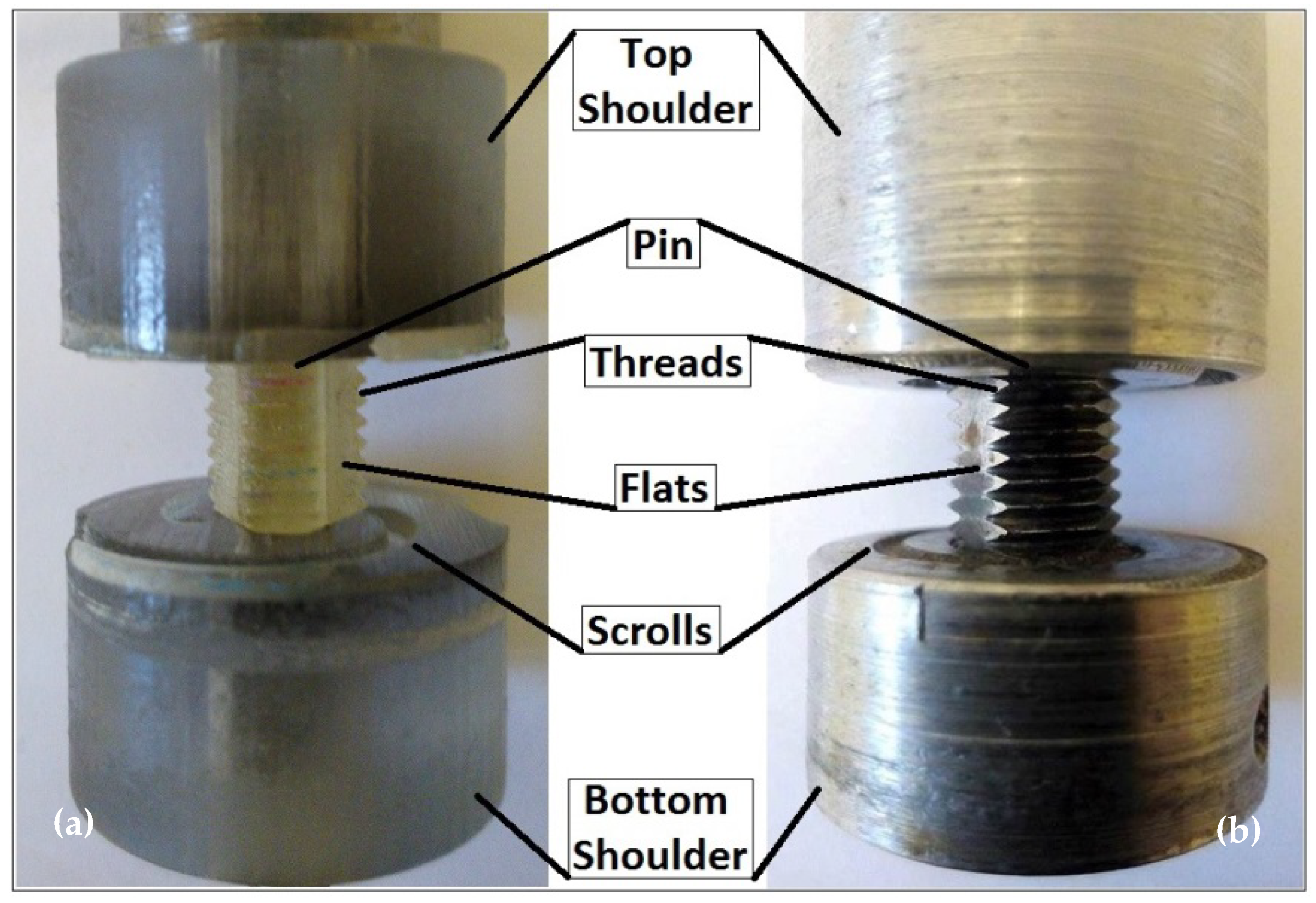
Friction stir welding (FSW) is a solid-state joining method whereby instead of melting the material, a rotating tool ploughs through the interface of the two plates to be joined. The bonded structure is obtained by mixing the material, softened by heat and stirring, generated from friction between the rotating tool and the workpiece [1]. There is a class of FSW tools called bobbin tools [2,3,4], consisting of two shoulders, one on each side of the workpiece surfaces, connected by the tool pin (Figure 1). Recent welding trials using this symmetric tool configuration (comprises two shoulders connected by an axial pin) have highlighted some of the benefits for a fast and less complicated process, compared to the conventional FSW [5].
One of the critical problems in bobbin friction stir welding (BFSW) is to provide an applicable instrument for optimization of the joining parameters and their side-effects on final quality of the weld [6]. This situation is crucial for bobbin-tool technique as the process settings are still in the early stages of study.
The general area of interest for the BFSW process is welding of light-alloys sheets, where there are many applications for this in marine, automotive, and aerospace fabrication processes [7,8,9]. Since, existence of defects can directly affect weld properties, making a reliable weld by the FSW process, in different situations and with different parameters, is difficult. Existence of a void as a defect is one of the challenges of work during bobbin-tool FSW process [10,11]. The objective of this research is to elucidate the origins of the formation mechanism of a typical tunnel void in the weld region. Identification of the influential phenomena in the creation of a void is required in developing a multi-physics model, based on the principles of fluid mechanics.
Bobbin-tool FSW appears to be a thermo-mechanical process as the frictional heat combined with the high plastic deformation is used for the joining process during the rotation and movement of the bobbin tool [12,13,14]. Also, changing the parameters of the process (e.g., feeding rate and rotational speed), or features of the bobbin tool (size and geometry of pin and shoulder), or the thickness and material properties of the weld plates may lead to unknown origin defects in the weld region [10,11]. In other words, there is no solid theory about the parameters of the process and method of control to achieve the optimum machine settings. Developing a comprehensive theory describing the process will extend the range of applicable process parameters and overall productivity. Thus, a transition from trial and error to a science-based approach is required to link the welding mechanism and operational variables.
For the first step in the investigation of weld region voids, it is intended to study the internal material flow regimes and how the failure of the flows causes weld defects [15]. However, the nature of the process makes it difficult to freeze the actual flow to validate a model [16,17,18]. In order to present an accurate multi-physics approach, near to real circumstances of the BFSW process, the basic interactions of the process parameters should be known in advance. Using an analogue model of the process and elucidation of relationships between effective parameters in creation and elimination of a void (tool features, process parameters and material capabilities), we can find the prerequisites of a numerical solution to effectively model the multi-physics of the situation. Our starting hypothesis for BFSW joining is based on a thermo-mechanical context of the process, as the solid-phase joining is simultaneously a result of plastic deformation and material displacement.
Instead of aluminum plates, analogue modelling of FSW was performed using colored layers and grids of plasticine. This provides easier flow visualization compared to the metallographic measurements of the aluminum welds. The objective is to see if it is possible to replicate the defect structures known to exist for aluminum plate welding. By fabrication of a plate comprising multiple layers of different colors, external area examination during and after the bobbin-tool FSW process, and subsequent post processing by cutting and viewing the cross-sections, can provide new insights into a flow-based model for the weld process.
2. Materials and Methods
For better visualization of the welding process, multi-layered plasticine slabs were used as the weld workpieces. Different colors of plasticine manufactured by New Clay Products–(Gordon Harris Ltd., London, UK), were rolled to a uniform thickness of approximately 1.25 mm by a cylinder-shaped roller and using glycerine as the lubricant.
Layers of different colors of plasticine were stacked on top of each other to create the test piece thickness of 10 mm. The slabs were subjected to heat treatment to improve the adhesion between the layers and also to diffuse the remained glycerine between the layers. The blocks were held at a temperature of 60 °C for a period of two hours. The hot blocks of plasticine cooled gradually to −4 °C as it was used for the processing in the room temperature.
To validate the plasticine analogue, an aluminum plate also was welded by the bobbin tool.
The single-piece bobbin-tool consists of a top-shoulder, a bottom-shoulder, and a fixed pin in the middle. The feature details of bobbin tools are identical for welding of both the aluminum and plasticine plates. However, the analogue models were tested by a 3D-printed plastic tool made on a Stratasys Connex machine, while the aluminum welds were performed by a metal tool made of H13 tool steel. The plastic-made tool has a better consistency with the non-metallic plasticine samples, and the steel-made tool is strong enough for processing of the aluminum plates.
The trials used a CNC milling machine (OKUMA, MX-45VAE Model, Oguchi Plant, Aichi, Japan). The weld workpieces were rigidly fixed between clamped bars and care was taken to ensure that no lateral movement during work occurs.
Based on prior experimentation, to achieve a uniform welded joint, the welding parameters, rotational speed (ω), and feeding rate (V), were selected in a range sufficient for the establishment of a bonded weld. In this regard, the plasticine analogue samples were processed under welding speed set of (ω = 50 rpm, V = 50 mm/min), as these were the minimum speeds of the milling machine. The aluminum sample was processed under speeds of (ω = 650 rpm, V = 400 mm/min). There was also a difference in the thickness of the workpieces, because of the limitation of the material instability under the processing condition. While the aluminum plate shows suitable processing in 6 mm thickness, the thickness of the analogue slabs increased to 10 mm to improve the stability of the layered plasticine during the process.
The dynamic analysis of the forces as the process response during real-time welding was recorded using the LabVIEW software. By a current (I) clamp meter, the signal trend recorded by the load cell transducers can analyze the variation in displacement under the material flow inconsistencies during the process.
After 100 mm advancement of the weld-line, the samples were taken for flow visualization and cross-sectioning. The weld characteristics and striation patterns were investigated by visual observation using a high-resolution digital camera (Fuji Fine-Pix S9500/Fujinon, Tokyo, Japan) for the plasticine analogue samples. Regarding the aluminum welds, the flow patterns of the cross-sections were delineated by a conventional metallographic procedure, etched by the Keller’s reagent, and the optical microscopy observation using the stereoscopic microscope (Olympus Metallurgical Microscope, Tokyo, Japan).
3. Results and Discussion
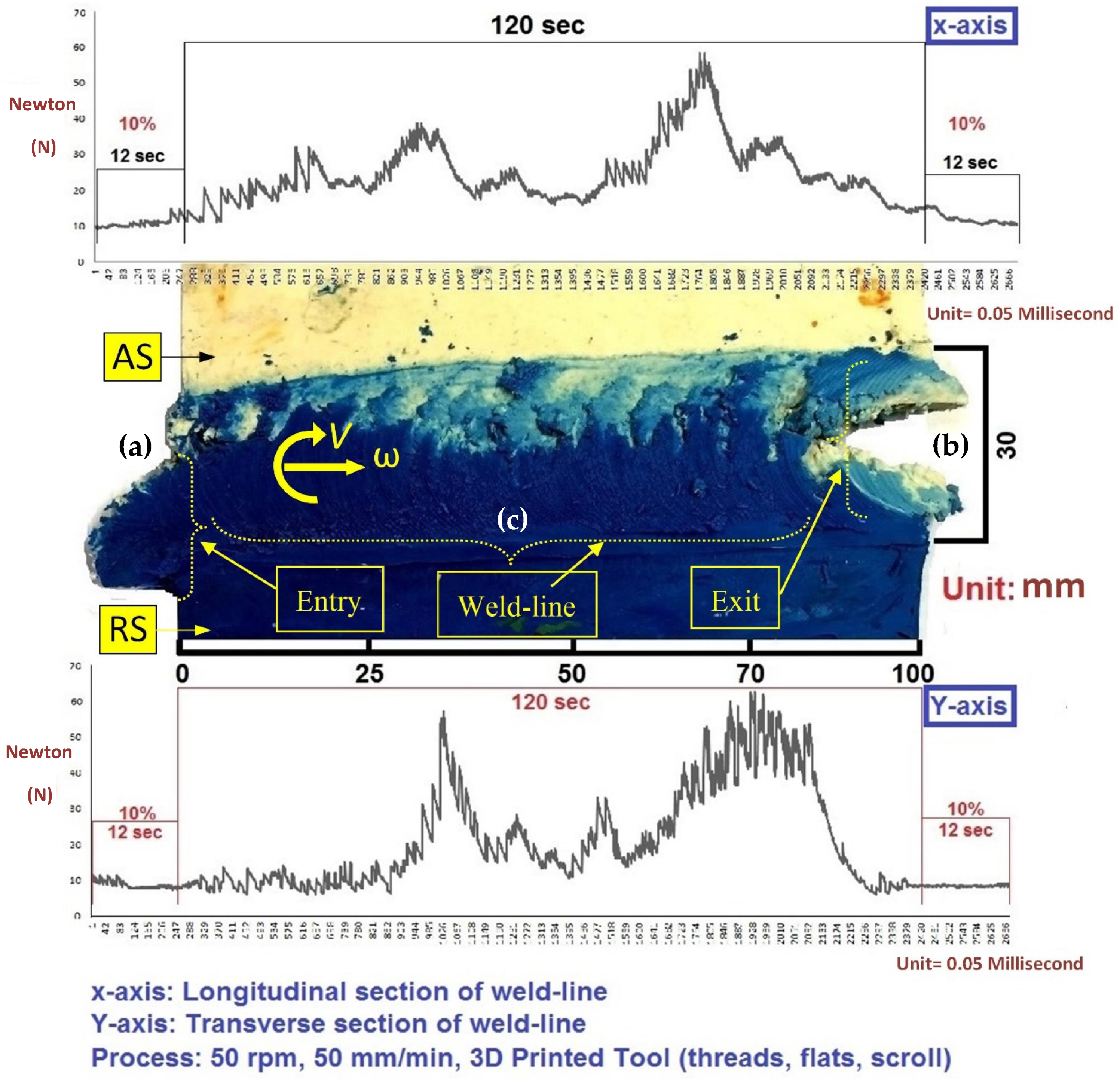
Figure 2 shows the physical appearance at the top plan view of the analogue plasticine sample after welding with the 3D printed plastic tool. The relevant dynamic force changes measured in longitudinal and traverse directions of the weld-line also are presented beside the weld analogue. The welded samples show two main defects at the entry and exit zones, as the inherent of the butt-joint bobbin weld. The welding process by the bobbin tool, there are three stages; entry, welding zone, and exit. The related areas for these three parts can be identified in the analogue model by the material movement patterns. The weld stage is located between the entry and exit. The entry can be characterized as a sudden high deformation which decreases over time before becoming stable as the tool travels completely into the plate. The exit phase is when the leading edge of the tool first starts to leave the plate, and material deformation decreases steadily with a sudden last drop of plastic deformation and disintegration of the material. The physical size of defects is corresponding with the dynamic changes of the load during the process.
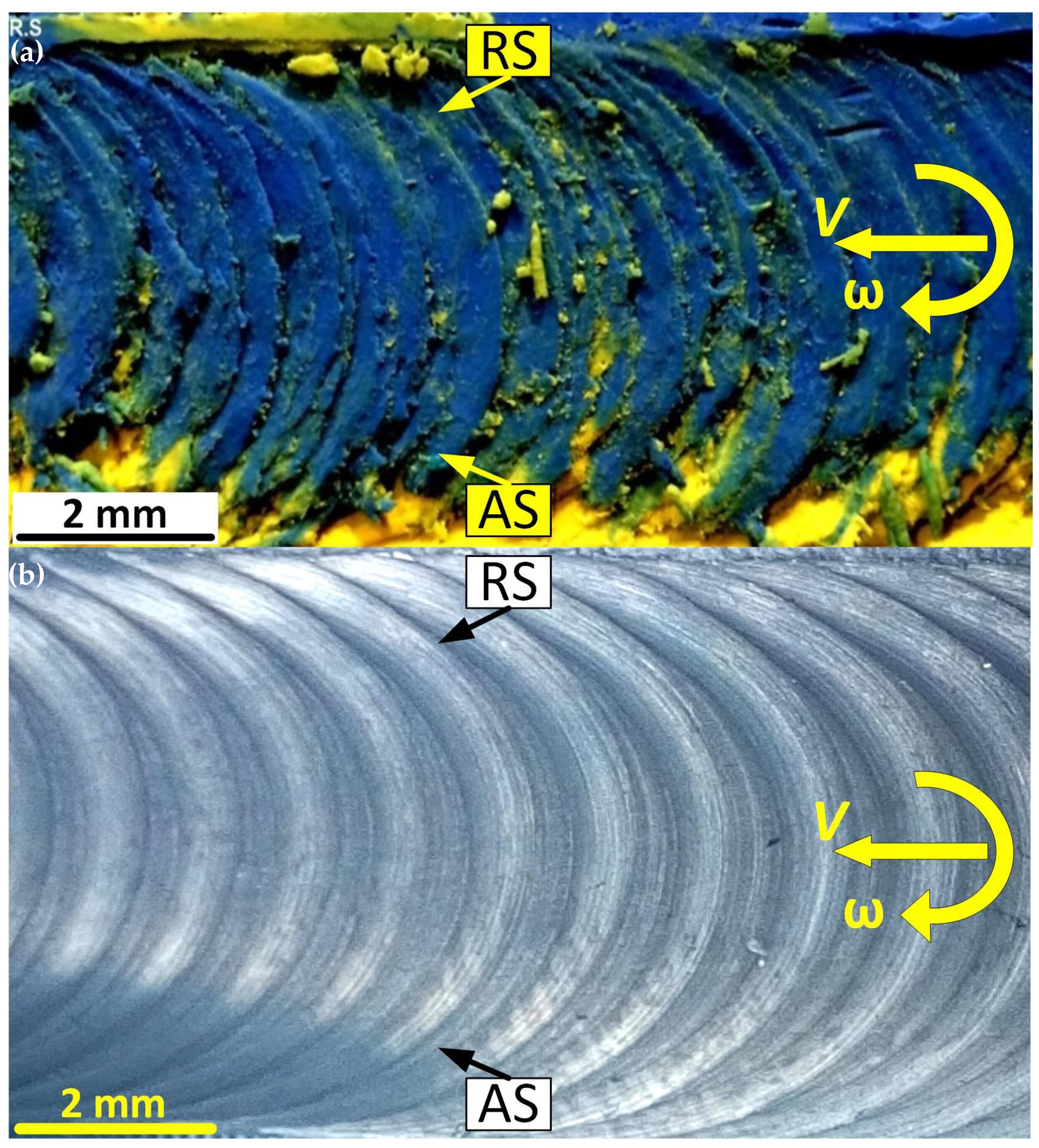
The surface appearance of the weld-seam shows a regular circular ripple pattern which is related to the shoulder performance during the advancement of the tool through the weld-line interface, see Figure 3. The comparison between these surface pitch ripples in analogue plasticine and aluminum welds shows high similarity in shape and size. Therefore, the formation mechanism of these circular surface patterns is relevant to the tool features and flow interaction underneath the scrolled shoulder. As a general interpretation, these pitch ripples are produced by the final ejection of the depositing mass layers at the trailing circumferential edge of the shoulder, during the longitudinal travelling of the tool. Although the pitch patterns have similar shapes in both analogue and metal samples, the actual size of the ripples can be defined by the speed ratio of the tool (relative feeding rate per rotation; distance per revolution). However, the overlapping of the combined successive revolutions makes it hard to provide an accurate measurement of the distance between the pitch layers to determine the optimized condition for the curved patterns of the weld surface.
The 3D printed plastic tool has a suitable mechanical consistency in its interaction with the substrate, regarding the observation of the physical changes in flow mechanism as the tool travels forward. The sample is suspected to contain more internal defects within the weld structure. Therefore, several extra samples were tested with the same tool features in different color patterns and under similar welding parameters to reveal more details of the internal flow mechanism during the bobbin friction stir welding.
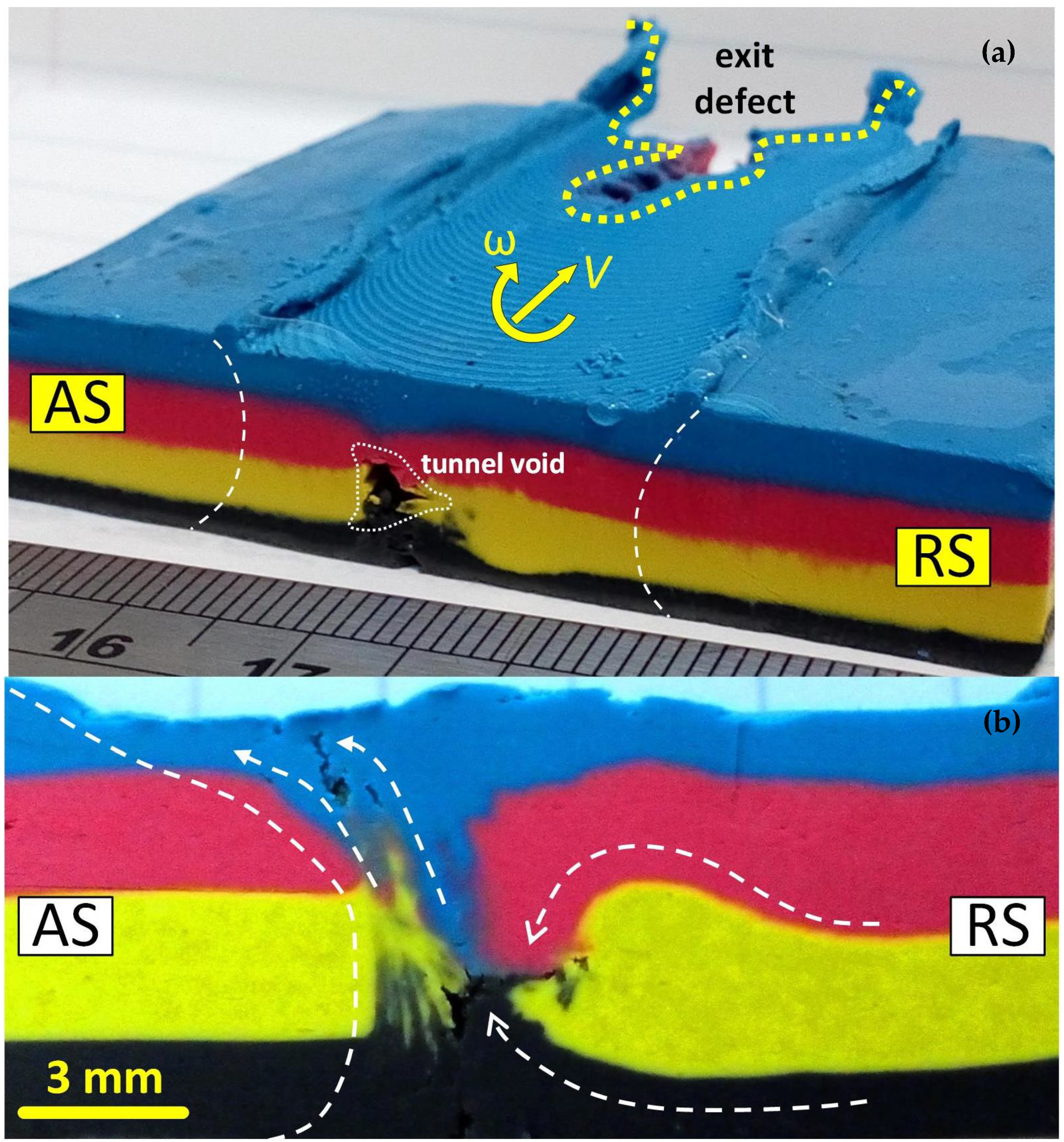
Figure 4 shows the cross-section of the plasticine weld in a multi-layered slab. Further details of the flow behavior at the cross-section of the analogue plasticine are observed in Figure 4b. The analogue model of the weld suggests a possible position for the tunnel defect between the entry zone and the exit zone of the weld (Figure 4a). Also, the nucleation of the defect in correspondence with the material flow interaction in the middle of the stirring zone is visible (Figure 4b).
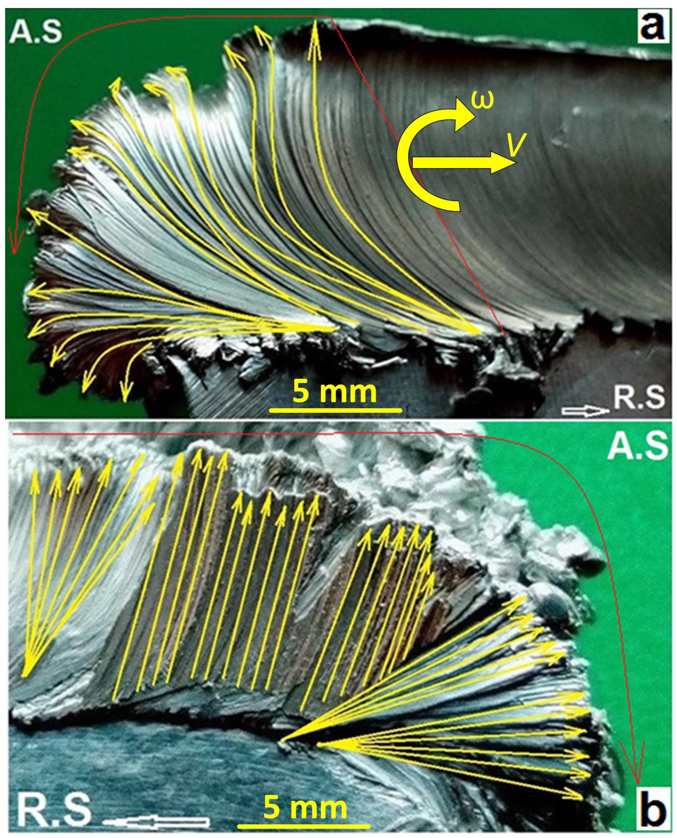
The previous research confirmed that the tunnel void originally forms at the entry zone. By including the flow visualization from the actual aluminum sample, compared with the analogue model, can construct a better understanding of the history of the flow interaction during the stirring process. Figure 5 and Figure 6 show some magnified views of the entry zone in aluminum weld sample. The flow patterns at the entry demonstrate the plastic deformation patterns caused at the substrate in interaction with the rotating tool. According to Figure 5, the initial deformation process at the entry zone contains highly plastic deformation in an unstable mode. As the unstable rotating tool passes through the weld-line, the plasticized mass underneath the shoulder escapes outwards the workpiece, whereby forms the spray zone at the entrance position of the tool. Because of the instability of the deformation, the plasticized mass curves from the advancing side (AS) and stretched to the retreating side (RS) of the clockwise rotating tool. The large discontinuity at the AS of the weld-line is the plausible position of the tunnel void as a flow-based defect.
The surface weld pattern typically shows a mixing pitched patterns as a result of the intercalation of the plasticized mass layers from both of the interface (AS and RS) come together to form the joint-line. The curved flow layers at the surface area of the entry zone can be the starting of these pitched surface patterns. Figure 5 reveals the twisting flow pattern of the plastic deformation in the entry spray of the aluminum weld. The striation lines of the plastic flow consolidated at the surface of the entry spray suggests that during the tool-substrate interaction, the simultaneous rotation and movement of the tool along with the edge of the workpiece caused a driving force for the strain planes underneath the shoulder. Because of the stirring action, the strain planes rotate with a twisting flow pattern. In this twisting flow mechanism, each plane after travelling a specified distance, can transform its driving force to the neighboring planes and become settled. Spatial location for each plane in the settlement position is in a different geometry in comparison with the original position. The consequence of these series of movements and settlements of the strain planes is a stirred zone in the body of the weld region.
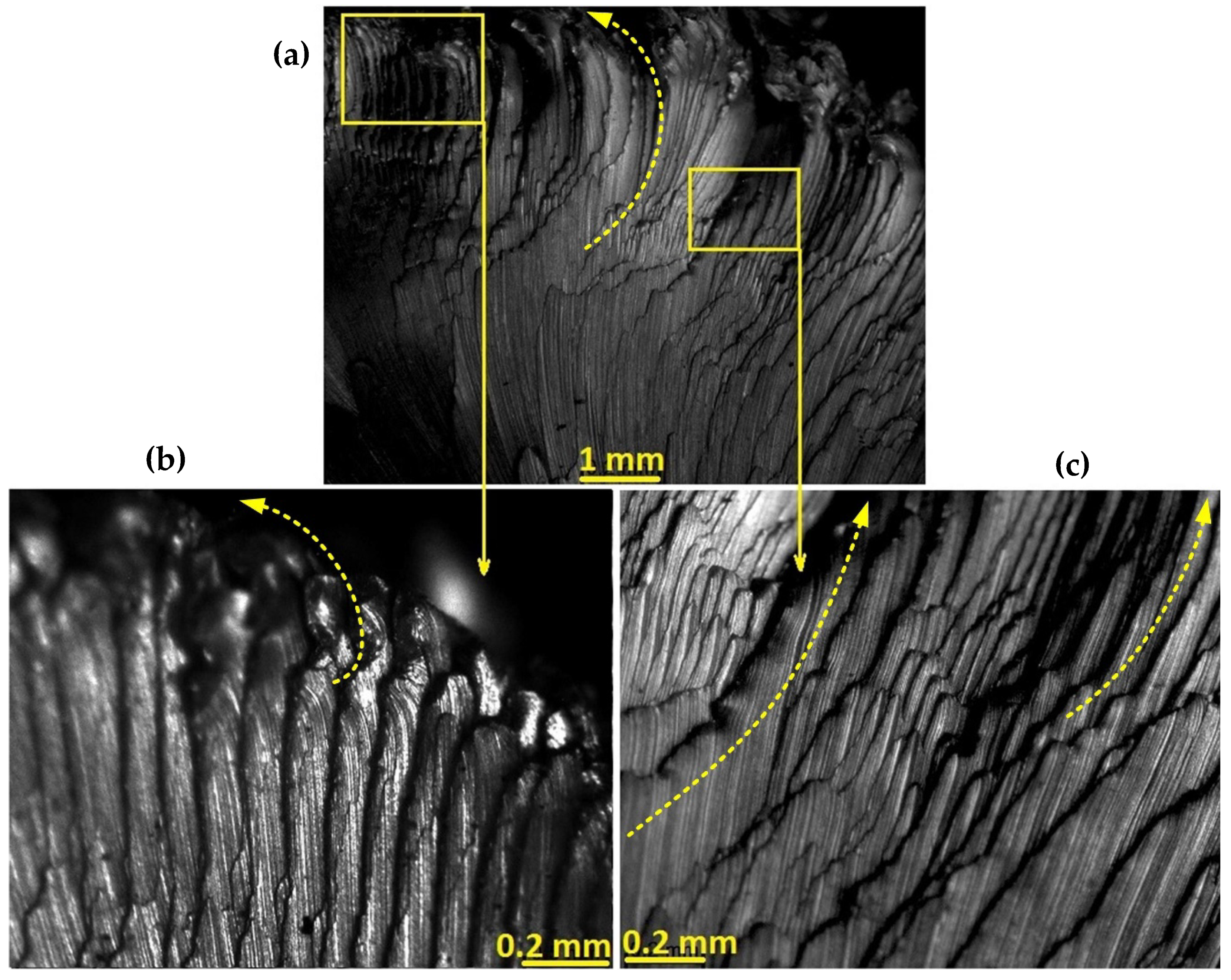
Since this twisting pattern caused a movement, there is a gap between the primary and new location of the planes. As it is illustrated in Figure 6, by pushing the stirring front to the entry zone (region c), a channelled flow in the neighborhood regions of the advancing side forms which are representative of the original position of materials before taking part in a stirred zone. In general, the surface flow lines are on a curvature direction from the advancing side toward the retreating side, according to the clockwise rotation of the bobbin tool. However, because of the scroll patterns inscribed on the shoulder surface, there is a bunching of the segmented contours which are formed as a continuous succession of the deposited mass. All of these successive segments are formed the spray region of entry zone. This continuous twisting movement can finally form a stirred zone for the bonding of the interface whereas there remains a tunnel defect as the footprint of unstable plastic deformation during the twisting pattern of plastic flow mechanism at the beginning of the stirring action.
For further analyzing the stirring action inside the workpiece, the material mixing phenomenon at the cross-sections of the plasticine analogue is shown in Figure 7.
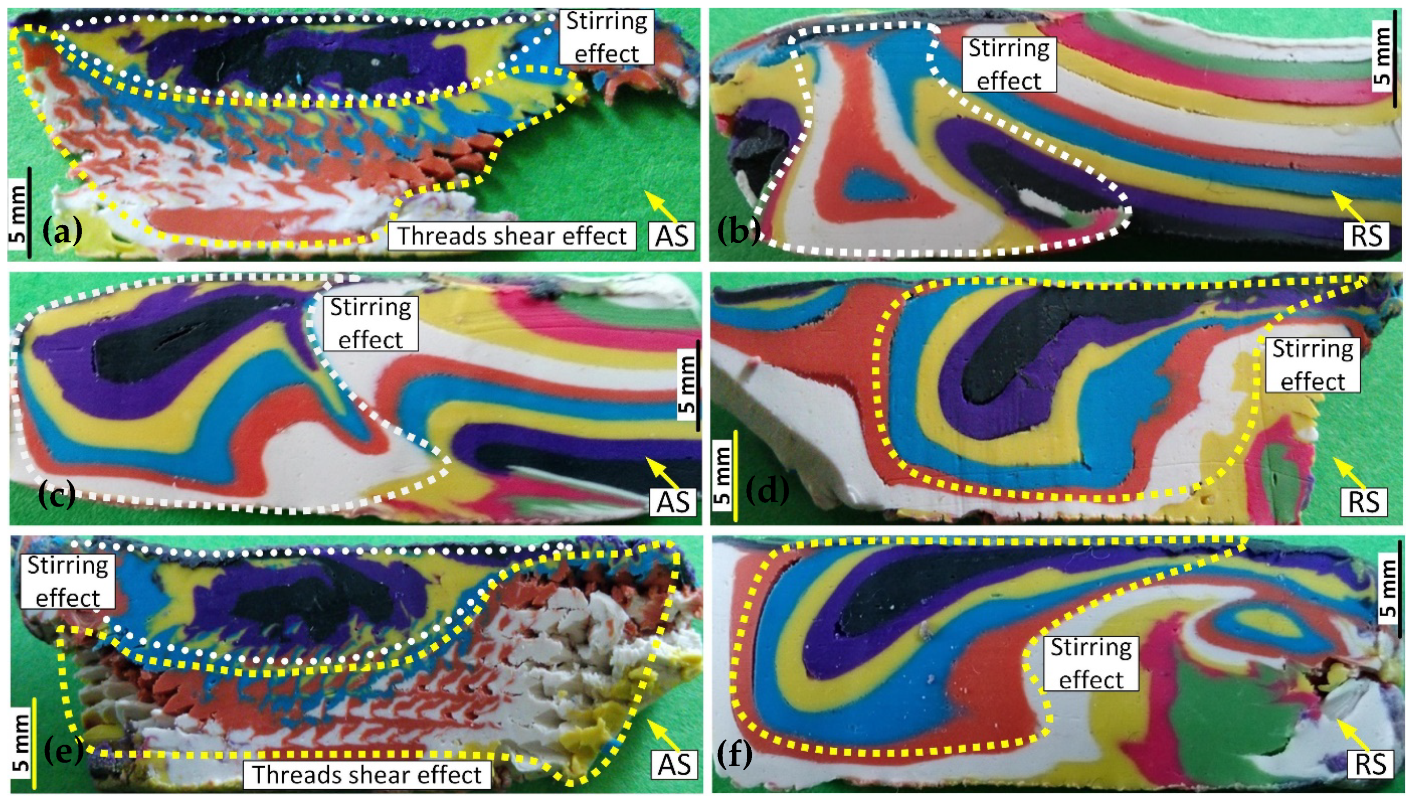
Figure 7 shows the material flow in three regions of entry zone, the body of weld and exit zone. Instead of one cross-section perpendicular to the welding direction, samples were cut at the AS and RS of the stirring zone at 45° angle on the welding direction. Figure 7a,b shows the cross-sections of the entry zone at the AS and RS, respectively. Figure 7a,e reveal the flock-shape patterns on the AS of the stirring zone, representative of the pin profile at the entry and exit zones, respectively. By the interaction between the threaded pin and the substrate, the material forms a vortex area near the bottom surface and a lamellar structure underneath the top shoulder. The RS cross-section shows an arc flow for the stirring zone with a curved wave mixing pattern at the position of the pin. Similar flow patterns are also visible in the exit zone, observed in Figure 7e,f, for the AS and RS of the weld-line, respectively. In both entry and exit zones, the birds-flock swarm pattern at the AS of the weld is representative of direct interaction between the threaded pin and the workpiece material which is inscribed around the hole defect because of the shortage of the refilling material to provide the integrity of the mass circulation.
The literature reports the middle of the stirring zone as the onion ring pattern. By generating a continuous refilling flow behind the tool, the plastic layers from the onion ring flow pattern at the contact region of the pin and the stirred mass. The flow trend for the onion rings can be conducted by the angle of the pin threads which result in a curved lamellar structure. Figure 7c,d, shows the flow patterns formed in the form of onion rings for the AS and RS cross-sections. Although both patterns demonstrate a similar curved lamellar pattern, the RS onion rings have better integrity between the flow layers. It implies the flow consistency at the leading edge of the pin, where the plasticized mass is transferred from AS to RS. The simultaneous advancement and rotation of the tool cause a flow complexity at the trailing edge of the pin (AS-to-RS transportation) whereby form a turbulent vortex flow deposited toward the AS. This is visible in all sections of Figure 7 that the flow lines in RS (Figure 7b,d,f) possess a more steady shape compared to the AS (Figure 7a,c,e). The discontinuity pattern at the AS region of the entry and exit zones represent the formation of the open tunnel void as the most common defect emerging at the BFSW weld structure.
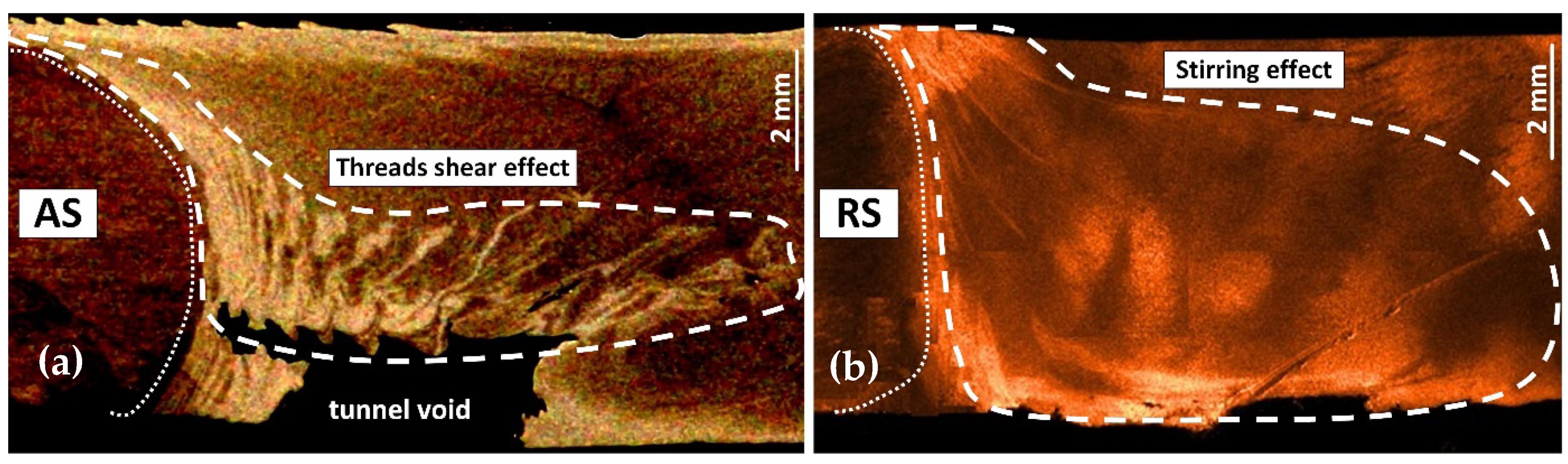
To validate the internal flow visualization of the BFSW weld obtained by the analogue plasticine, these flow patterns need to be compared with the actual weld samples. Figure 8 shows the etched weld samples selected from the AS and RS cross-sections of the entry zone, similar regions in Figure 7a,b, respectively. In the case of the AS, Figure 8a demonstrates an open void surrounded by the birds-flock swarm patterns, similar to Figure 7a. as the tool passes from the entry zone, the void deficiency emerged at the AS interface. However, the forging effect of the tool at the RS generates a refilling effect whereby it forms the onion ring pattern in the stirring zone, see Figure 8b. The flow lines at the RS interface shows a lamellar structure, moving with a horizontal trend from the top surface underneath the top shoulder to the center of the stir zone. This flow detail in the RS (Figure 8b) indicates an optimized refilling at the trailing edge of the tool without void occurrence. It confirms that for integrity in the refilling mechanism, the simultaneous performance of the pin and shoulder should generate an overlapped mass flow which can cover the material deficit after the tool leaves the stirring position.
During the FSW process, the first evidence of plastic deformation and material flow needs to be explored in the entry zone. In the entry zone, even before entering the pin into the workpiece, the flow regime is affected by the rotating movement of the shoulder. Since the position of the shoulder edge is located ahead of the pin, therefore the first stage of the entry zone as the ejected spray is the consequence of the pure plastic flow imposed by the shoulder. It should be noted that the flow features in the spray zone outside of the workpiece, is totally different from the surface flow features of the weld track.
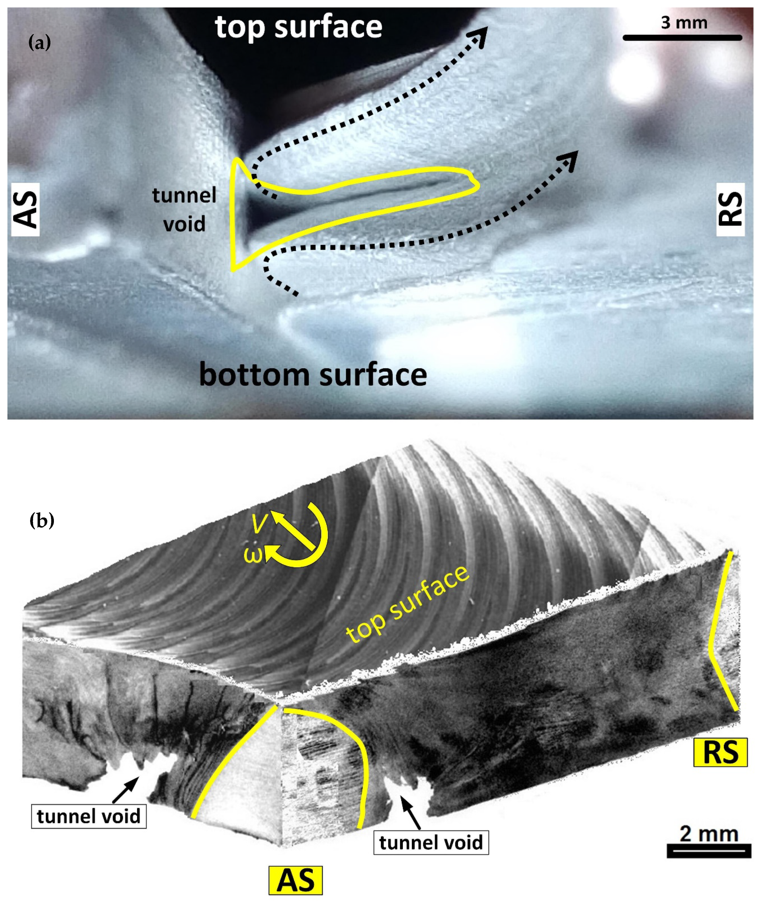
Figure 9 shows the metallographic observations of the plastic internal flow patterns at the body of the weld with a focus on the tunnel void region. Figure 9a demonstrates the tunnel void occurred at the spray region at the beginning of the entry zone. The angle of view imaging can portray more details of the plasticized mass, accumulated outwards of the weld-seam. Because of the absence of the pin in the plastic deformation, spray region is sagging to the one side (bending towards the RS). As there is no backup material behind the movement direction, the mass is plasticized between two shoulders and then through the shoulders gap is ejected outside.
To be more focused on the flow history around the tunnel void, a 3D photomontage of the stereoscopic images, depicting the left-eye and right-eye views of the tunnel void position is shown in Figure 9b. According to the stereograph pictures of Figure 9b, the surface pitch ripples features are also observed as the curved flow induced by the shoulder rotation in a circle route between the AS and the RS. Regarding the weld cross-sections, the wavy flow layers accumulated at the circumferential edge of the tunnel void elucidates turbulent flow regimes strayed in random directions causing the flow discontinuity.
The origins of these dispersed flow lines can be attributed to the plasticizing rotation of the shoulder in contrary with the pin-induced flow at the trailing edge of the tool, while the plasticized layers of the stirred mass are depositing to form the weld-seam. Therefore, incomplete refilling at the AS forms a kinked-shape discontinuity at the weld-track known as the tunnel void.
4. Discussion
The main aim of this study was to predict the position of the tunnel defect based on the analogue model to elucidate the flow-based formation mechanism. Based on the analogue flow visualization at the cross-section, a simplified physical model can summarize the general flow behavior of the process during the interaction between the tool and the substrate. The tool features in bobbin-FSW process generate a specific inherent flow interaction around the tool, compared to the conventional-FSW. Although different defect geometries (open tunnel\void) were observed in flow visualization of the analogue model, the flow mechanism is proposed to be similar. By comparing the weld cross-sections in plasticine analogue and aluminum weld, it was found that the tunnel defect is commonly formed at the advancing side of the tool near the bottom surface. This can be attributed to the sequence of the material transportation relevant to the tool features and the welding process setup.
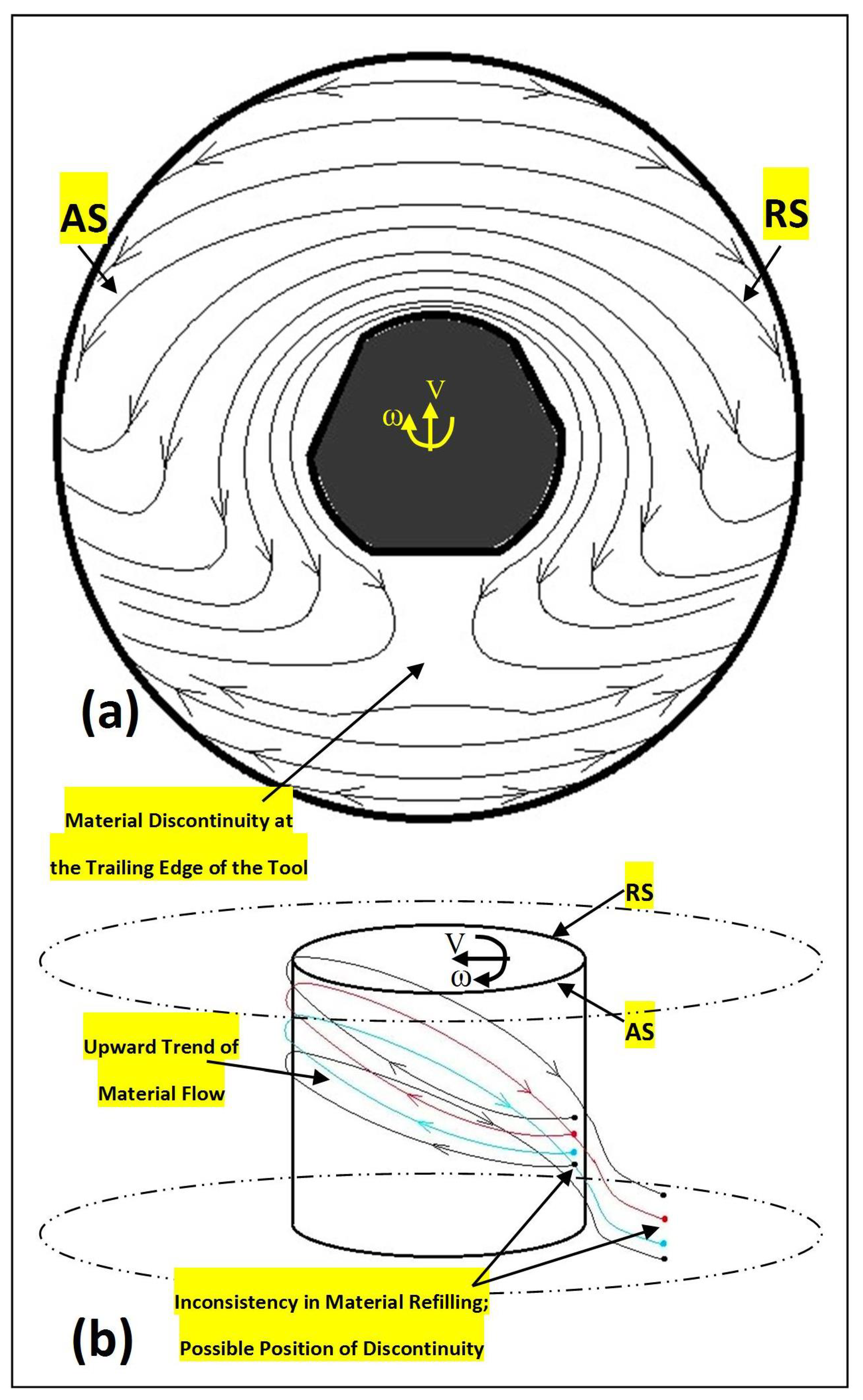
Figure 10 presents the details of the flow lines at the proximity of the tool components (shoulder and pin). The plain view of the plastic flow underneath the shoulder is shown in Figure 10a. It is shown that by entering the pin to the substrate, the materials undergo a local discontinuity caused by the shearing effect of the rotating tool. After circulating of the plastic mass around the pin, the stirred materials are being deposited at the trailing edge of the tool. In this situation, the flow inconsistency can cause a mass deficit between the deposited layers, resulting in void occurrence. It seems that the rotating pin has more responsibility regarding the internal flow features within the stirring zone. Hence, for a better explanation, the mass flow pattern around the pin is drawn in Figure 10b. The side view of the tool in Figure 10b shows that the clockwise rotation in the presence of threads on pin pulls the mass flow upwards. Therefore, the upward trend pumps material vertically from the advancing side to the leading edge of the tool, and simultaneously the fresh material of the retreating side are swept to the trailing edge of the tool. This helical flow path for transportation of the stirred mass cause a refilling inconsistency, in the form of the escape of the material at the backside of the tool, which increases the possibility of the material deficit at the bottom of the advancing side where the material is expected to be deposited after the circulation around the pin. This is where the incomplete filling deficit and eventually a tunnel void emerge as the discontinuity defect between the deposited mass layers.
The pitch threads have a positive influence on stirring performance by the increase in velocity of transportation and a helix angle and thus better plastic flow condition at the leading edge of the tool. However, this helical flow path affects the efficiency of the adhesion of the material to the pin during the transportation at the trailing edge of the tool, between AS-to-RS. This is consistent with the cross-section observations which clearly shows that the turbulent-like flow features at the advancing side towards the bottom surface form an open tunnel void defect.
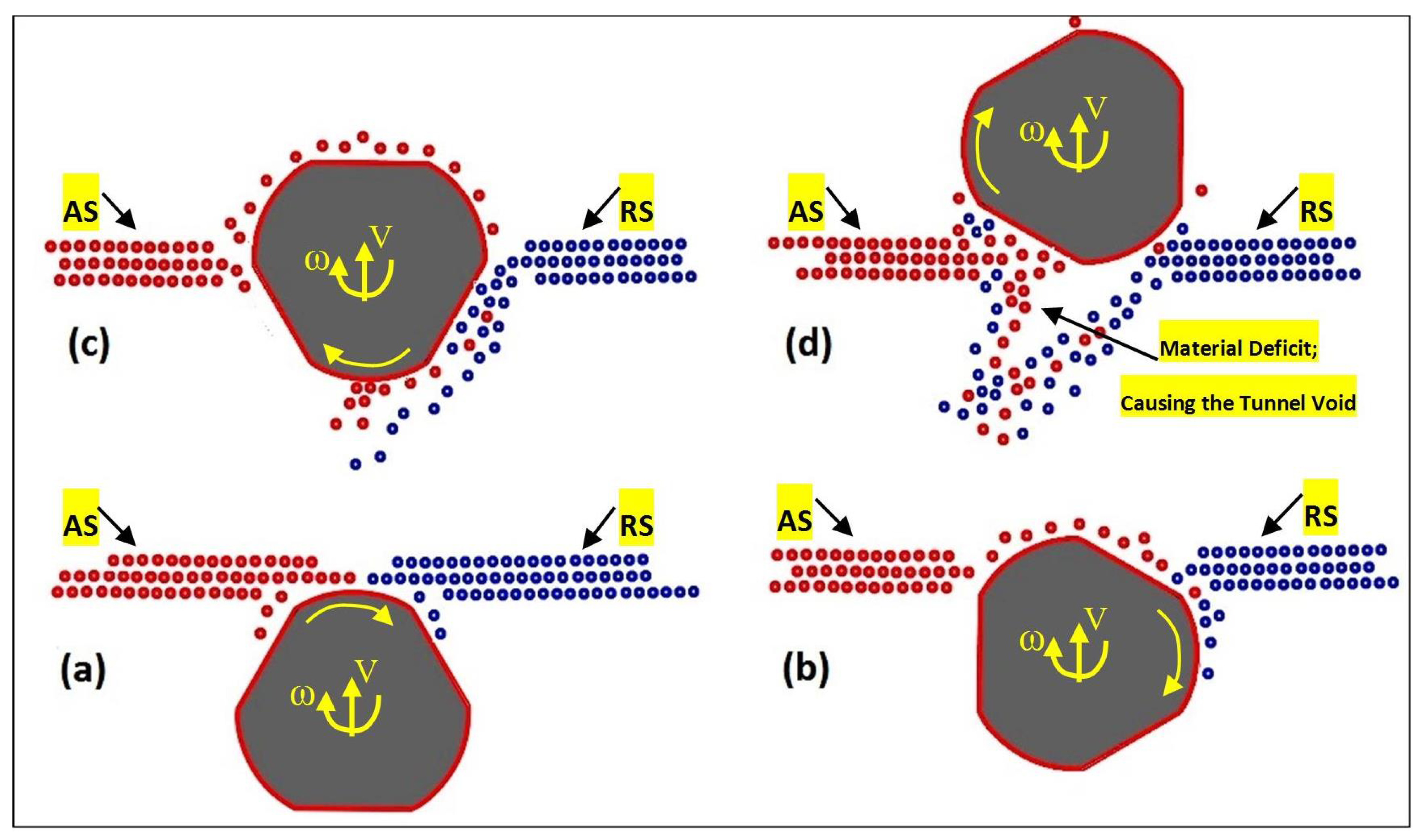
The schematic of the dynamic material flow can be shown around the rotating pin in plain view to elucidate the pin-material interaction with a focus on void formation mechanism. Figure 11 demonstrates the sequence of material flow around the pin, based on the flow behavior identified in this work. Referring to the flow visualization developed in this work, by the clockwise rotation of the tool, the material at the AS is stirred and transported to the RS.
By entering the tool into the substrate, the pin grabs the material from the leading edge of the tool, see Figure 11a. By further advancement of the tool trough the butt-interface locus, the sharp edges of the pin (threads-flats) dig into the workpiece material (Figure 11b). This yields more plasticized mass at the trailing edge of the pin. The clockwise rotation of the pin causes an opposite mass flowing at the retreating side of the tool, squeezing the transported material from the leading edge backwards at the trailing edge of the pin (Figure 11c). However, because of the opposite direction of the rotational and advancing movement of the pin at the retreating side, the plastic flow tends to escape from the edge of the pin surface during transport to the back of the tool. This lateral escaping mass from the pin surface causes a slipping mode in material transportation which decreases the compression and integrity of the flow layers at the trailing edge. This explains the flow failure by observing a discontinuity pattern in RS-to-AS recirculating flow path as the potential position for the formation of the tunnel void and emerging of the incomplete weld (Figure 11d).
By repeating this flow inconsistency behavior during successive rotation of the pin, the deficit in material flow forms a channel-shaped tunnel void as a flow-based defect. In addition to the tool geometry, it seems that the lack of mixing and insufficient material refilling at the AS also are effective in the evolution of the tunnel. This can be overcome by applying higher welding speeds (both rotational and advancing velocity).
5. Conclusions
This research illustrates an original contribution by introducing an analogue modelling process of BT-FSW to visualize deformation and joining of the material. The method is applicable to identify the flow characteristic of the weld and present probable formation mechanism of the discontinuity defects for the processed material. The reported results point out a very strong model based on the flow visualization by the plasticine analogue during the friction stir welding process. Results show that the main reason for the tunnel defect is the instability of the plastic deformation during the entering of the tool into the body of the workpiece material at the entry zone. This highly plastic embedding occurs with the ejection of material as a spray in the entry zone of the weld and consequently, the tunnel defect is left in the place of the material loss. By identification of the origins of the void formation, it was concluded that a defect-free weld should be able to establish the uniform flow integrity within the stirring zone. This can result in a stable mass refilling process at the trailing edge of the tool, where the mass deposition forms the weld seam with no discontinuity flaw within the bonding layers.
Author Contributions
Conceptualization, A.T. and D.J.P.; methodology, A.T.; validation, A.T.; formal analysis, A.T. and D.J.P.; writing—original draft preparation, A.T.; writing—review and editing, A.T., D.J.P., and D.C.; supervision, D.J.P. and D.C. All authors have read and agreed to the published version of the manuscript.
Funding
This research received no external funding.
Conflicts of Interest
The authors declare no conflict of interest.
References
- Colligan, K. Material flow behavior during friction welding of aluminum. Weld J. 1999, 75, 229s–237s. [Google Scholar]
- Sued, M.; Pons, D.; Lavroff, J.; Wong, E.-H. Design features for bobbin friction stir welding tools: Development of a conceptual model linking the underlying physics to the production process. Mater. Des. (1980–2015) 2014, 54, 632–643. [Google Scholar] [CrossRef]
- Thomas, W.; Wiesner, C.; Marks, D.; Staines, D. Conventional and bobbin friction stir welding of 12% chromium alloy steel using composite refractory tool materials. Sci. Technol. Weld. Join. 2009, 14, 247–253. [Google Scholar] [CrossRef]
- Threadgill, P.L.; Ahmed, M.; Martin, J.P.; Perrett, J.G.; Wynne, B.P. The use of bobbin tools for friction stir welding of aluminium alloys. Mater. Sci. Forum 2010, 638, 1179–1184. [Google Scholar] [CrossRef]
- Threadgill, P.; Leonard, A.; Shercliff, H.; Withers, P. Friction stir welding of aluminium alloys. Int. Mater. Rev. 2009, 54, 49–93. [Google Scholar] [CrossRef]
- Sued, M.K. Fixed Bobbin Friction Stir Welding of Marine Grade Aluminium. Ph.D. Thesis, University of Canterbury, Christchurch, New Zealand, 2015. [Google Scholar]
- Fuse, K.; Badheka, V. Bobbin tool friction stir welding: A review. Sci. Technol. Weld. Join. 2019, 24, 277–304. [Google Scholar] [CrossRef]
- Wang, G.-Q.; Zhao, Y.-H.; Tang, Y.-Y. Research progress of bobbin tool friction stir welding of aluminum alloys: A review. Acta Metall. Sin. (Engl. Lett.) 2019. [Google Scholar] [CrossRef] [Green Version]
- Trueba, L.; Torres, M.A.; Johannes, L.B.; Rybicki, D. Process optimization in the self-reacting friction stir welding of aluminum 6061-t6. Int. J. Mater. Form. 2018, 11, 559–570. [Google Scholar] [CrossRef]
- Tamadon, A.; Pons, D.J.; Clucas, D.; Sued, K. Internal material flow layers in AA6082-T6 butt-joints during bobbin friction stir welding. Metals 2019, 9, 1059. [Google Scholar] [CrossRef] [Green Version]
- Tamadon, A.; Pons, D.; Sued, K.; Clucas, D. Formation mechanisms for entry and exit defects in bobbin friction stir welding. Metals 2018, 8, 33. [Google Scholar] [CrossRef] [Green Version]
- Tamadon, A.; Pons, D.; Sued, K.; Clucas, D. Thermomechanical grain refinement in aa6082-t6 thin plates under bobbin friction stir welding. Metals 2018, 8, 375. [Google Scholar] [CrossRef] [Green Version]
- Tamadon, A.; Pons, D.J.; Clucas, D.; Sued, K. Texture evolution in aa6082-t6 bfsw welds: Optical microscopy and ebsd characterisation. Materials 2019, 12, 3215. [Google Scholar] [CrossRef] [PubMed] [Green Version]
- Tamadon, A.; Pons, D.J.; Clucas, D. Afm characterization of stir-induced micro-flow features within the aa6082-t6 bfsw welds. Technologies 2019, 7, 80. [Google Scholar] [CrossRef] [Green Version]
- Tamadon, A.; Pons, D.; Sued, K.; Clucas, D. Development of metallographic etchants for the microstructure evolution of a6082-t6 bfsw welds. Metals 2017, 7, 423. [Google Scholar] [CrossRef] [Green Version]
- Tamadon, A.; Pons, D.; Sued, M.; Clucas, D.; Wong, E. Preparation of plasticine material for analogue modelling. In Proceedings of the International Conference on Innovative Design and Manufacturing (ICIDM2016), Auckland, New Zealand, 24–26 January 2016. [Google Scholar]
- Tamadon, A.; Pons, D.; Sued, M.; Clucas, D.; Wong, E. Analogue Modelling of Bobbin Tool Friction Stir Welding. In Proceedings of the International Conference on Innovative Design and Manufacturing (ICIDM2016), Auckland, New Zealand, 24–26 January 2016. [Google Scholar]
- Sued, M.; Tamadon, A.; Pons, D. Material flow visualization in bobbin friction stir welding by analogue model. Proc. Mech. Eng. Res. Day 2017, 2017, 1–2. [Google Scholar]
Figure 1.
The apparent geometry features of the bobbin tools used for the analogue and aluminum welds; (a) 3D-printed plastic tool utilized for the plasticine analogue, (b) H13 steel tool for the aluminum welding.
Figure 1.
The apparent geometry features of the bobbin tools used for the analogue and aluminum welds; (a) 3D-printed plastic tool utilized for the plasticine analogue, (b) H13 steel tool for the aluminum welding.

Figure 2.
Photograph of the bobbin friction stir welding (BFSW) section sample (top surface): plasticine analogue model. (a) Entry zone of weld. (b) Exit zone of weld. (c) Weld-line body, through the weld-line.
Figure 2.
Photograph of the bobbin friction stir welding (BFSW) section sample (top surface): plasticine analogue model. (a) Entry zone of weld. (b) Exit zone of weld. (c) Weld-line body, through the weld-line.

Figure 3.
In situ model of the tear drop pattern through the weld-line; (a) plasticine analogue, (b) aluminum weld sample.
Figure 3.
In situ model of the tear drop pattern through the weld-line; (a) plasticine analogue, (b) aluminum weld sample.

Figure 4.
Photograph of the BFSW section sample; plasticine analogue. (a) A model for the possible position of tunnel void, (b) weld cross-section, representative of the flow patterns.
Figure 4.
Photograph of the BFSW section sample; plasticine analogue. (a) A model for the possible position of tunnel void, (b) weld cross-section, representative of the flow patterns.

Figure 5.
Flow patterns of plastic deformation in the entry zone; aluminum weld sample. (a) Top surface, (b) bottom surface.
Figure 5.
Flow patterns of plastic deformation in the entry zone; aluminum weld sample. (a) Top surface, (b) bottom surface.

Figure 6.
Twisting model for the plastic deformation in the stirred zone of the entry spray. (a) Edge view of the spray region. (b,c) Surface patterns in higher magnification.
Figure 6.
Twisting model for the plastic deformation in the stirred zone of the entry spray. (a) Edge view of the spray region. (b,c) Surface patterns in higher magnification.

Figure 7.
The cross-sections of the stirring zone showing the internal flow details for the plasticine analogue sample; (a,b) cross-sections of the entry zone; the advancing side (AS) and retreating side (RS) transverse sections, respectively; (c,d) cross-sections of the mid-weld; the AS and RS transverse sections, respectively; (e,f) cross-sections of the exit zone; the AS and RS transverse sections, respectively.

Figure 8.
The cross-sections of the stirring zone showing the internal flow details for the AA6082-T6 BFSW weld sample; (a,b) the entry zone; the AS and RS transverse sections, respectively.
Figure 8.
The cross-sections of the stirring zone showing the internal flow details for the AA6082-T6 BFSW weld sample; (a,b) the entry zone; the AS and RS transverse sections, respectively.

Figure 9.
Details of the apparent features of the tunnel void within the AA6082-T6 aluminum weld; (a) tunnel void emerged at the entry location of the weld, (b) photo-montage pattern of the tunnel void within the weld structure, revealed in cross-section and side view of the weld.
Figure 9.
Details of the apparent features of the tunnel void within the AA6082-T6 aluminum weld; (a) tunnel void emerged at the entry location of the weld, (b) photo-montage pattern of the tunnel void within the weld structure, revealed in cross-section and side view of the weld.

Figure 10.
The schematic of the flow features under the shoulder, around the pin; (a) top view of the flow model under the shoulder, (b) side-view of the flow lines around the rotating pin.
Figure 10.
The schematic of the flow features under the shoulder, around the pin; (a) top view of the flow model under the shoulder, (b) side-view of the flow lines around the rotating pin.

Figure 11.
The proposed physical model for the material flow regimes in interaction between the pin and the workpiece material; (a) initial contact between the rotating tool and the workpiece material, (b,c) entering of the pin into the substrate mass, start of the plastic deformation, (d) fully embedment of the pin into plasticized mass of the substrate with a tunnel void discontinuity formed at the trailing edge of the tool. (All schematic flow patterns are presented at the top-view of the pin and substrate).

© 2019 by the authors. Licensee MDPI, Basel, Switzerland. This article is an open access article distributed under the terms and conditions of the Creative Commons Attribution (CC BY) license (http://creativecommons.org/licenses/by/4.0/).
Share and Cite
MDPI and ACS Style
Tamadon, A.; Pons, D.J.; Clucas, D. Structural Anatomy of Tunnel Void Defect in Bobbin Friction Stir Welding, Elucidated by the Analogue Modelling. Appl. Syst. Innov. 2020, 3, 2. https://0-doi-org.brum.beds.ac.uk/10.3390/asi3010002
AMA Style
Tamadon A, Pons DJ, Clucas D. Structural Anatomy of Tunnel Void Defect in Bobbin Friction Stir Welding, Elucidated by the Analogue Modelling. Applied System Innovation. 2020; 3(1):2. https://0-doi-org.brum.beds.ac.uk/10.3390/asi3010002
Chicago/Turabian StyleTamadon, Abbas, Dirk J. Pons, and Don Clucas. 2020. "Structural Anatomy of Tunnel Void Defect in Bobbin Friction Stir Welding, Elucidated by the Analogue Modelling" Applied System Innovation 3, no. 1: 2. https://0-doi-org.brum.beds.ac.uk/10.3390/asi3010002