
Absorption and Strength Properties of Short Carbon Fiber Reinforced Mortar Composite


1
Angelo DelZotto School of Construction Management, George Brown College, 146 Kendal Avenue, Toronto, ON M5T 2T9, Canada
2
Department of Civil Engineering, Faculty of Engineering and Architectural Science, Ryerson University, 350 Victoria Street, Toronto, ON M5B 2K3, Canada
3
Department of Civil and Environmental Engineering, Faculty of Engineering, University of Windsor, 401 Sunset Avenue, Windsor, ON N9B 3P4, Canada
*
Author to whom correspondence should be addressed.
Buildings 2021, 11(7), 300; https://0-doi-org.brum.beds.ac.uk/10.3390/buildings11070300
Submission received: 8 June 2021
/
Revised: 4 July 2021
/
Accepted: 6 July 2021
/
Published: 8 July 2021
(This article belongs to the Special Issue Buildings: 10th Anniversary)
Abstract
:This paper presents the water absorption and strength properties of short carbon fiber reinforced mortar (CFRM) composite. Four CFRM composites with 1%, 2%, 3%, and 4% short pitch-based carbon fibers were produced in this study. Normal Portland cement mortar (NCPM) was also prepared for use as the control mortar. The freshly mixed mortar composites were tested for workability, wet density, and entrapped air content. In addition, the hardened mortar composites were examined for compressive strength, splitting tensile strength, flexural strength, and water absorption at the ages of 7 and 28 days. The effects of different carbon fiber contents on the tested properties were observed. Test results showed that the incorporation of carbon fibers decreased the workability and wet density, but increased the entrapped air content in mortar composite. Most interestingly, the compressive strength of CFRM composite increased up to 3% carbon fiber content and then it declined significantly for 4% fiber content, depending on the workability and compaction of the mortar. In contrast, the splitting tensile strength and flexural strength of the CFRM composite increased for all fiber contents due to the greater cracking resistance and improved bond strength of the carbon fibers in the mortar. The presence of short pitch-based carbon fibers significantly strengthened the mortar by bridging the microcracks, resisting the propagation of these minute cracks, and impeding the growth of macrocracks. Furthermore, the water absorption of CFRM composite decreased up to 3% carbon fiber content and then it increased substantially for 4% fiber content, depending on the entrapped air content of the mortar. The overall test results suggest that the mortar with 3% carbon fibers is the optimum CFRM composite based on the tested properties.
1. Introduction
Cement-based mortar is widely used because of its many beneficial properties, including good compressive strength, high fire resistance, ease of application, and low cost. Unfortunately, cement mortar possesses very low tensile and flexural strengths, limited ductility, and little resistance to cracking. It exhibits an elastic brittle behavior under tensile stresses. The primary reason for such weakness of cement mortar is its inability to resist the initiation and growth of cracks due to relatively low tensile strength [1]. Internal microcracks are inherently present in cement-based composites, such as mortar and concrete. When loaded, these microcracks propagate and gradually connect to each other. Due to poor tensile strength, the connectivity of microcracks increases and results in macrocracks that lead to the brittle fracture in cement-based composites. This inherent deficiency can be overcome by adding fibers, as they arrest the cracks and allow much larger deformation beyond the peak stress [2]. Many studies have reported that short fibers substantially improve the performance of cement-based composites under tensile and flexural loadings [3,4,5,6,7,8]. Fibers with a length less than ½ inch (12.7 mm) are generally defined as “short fibers” [9]. The incorporation of randomly distributed short fibers into cement-based materials increases their tensile and flexural strengths by preventing or controlling the initiation, propagation, and connectivity of cracks [10,11,12,13,14].
In the past, asbestos cement incorporating asbestos fibers was widely used as a fiber reinforced cement-based material [15]. Asbestos fibers were used in the construction industry for many years, particularly in thin sheet applications. Unfortunately, asbestos fibers were found to cause critical health issues, such as fibrosis and lung cancer [16]. Then researchers and practitioners looked for alternative fibers, which are medically safe for construction workers and the public. The quest for safe and sound fibers brought glass, cellulose, and steel fibers to the construction industry, but they showed certain durability issues. Glass fibers exhibited embrittlement and strength loss problems [17], cellulose fibers showed moisture sensitivity issues [18], and steel fibers exposed on the surface appeared to have corrosion problems [19]. The durability issues of the above-mentioned fibers steered the construction industry to find medically safe and physically durable fibers. Thereafter, many other fibers were incorporated into cement-based materials. Amongst these, polypropylene, polyvinyl alcohol, and carbon fibers are noteworthy.
Short carbon fibers appeared first in the construction industry of Japan, for use in cement composites, and became attractive due to their greater weatherability, thermal resistance, and long-term chemical stability compared to glass, polypropylene, and steel fibers; in addition, they exhibit good mixability and finishability when used in cement composites [20]. Carbon fibers are inert and medically safe for humans; they are physically strong like steel fibers and more durable than glass fibers in aggressive environments. Additionally, carbon fibers are lighter, and they provide higher strength than many other fibers despite their lower density [1]. Historically, polyacrylonitrile (PAN)-based carbon fibers were initially used in cement composites [21]. It can make cement-based composites more durable than polyvinyl alcohol and polypropylene due to a lower porosity, a smaller fraction of large capillary pores, and a less entrapped air content, contributing to a better impermeability [22]. However, PAN-based carbon fibers were cost-prohibitive and therefore its applications were not widespread in the construction industry. Such a barrier was removed with the invention of pitch-based carbon fibers. Due to lower prices, short pitch-based carbon fibers have been used for many building applications [20,23,24,25].
Extensive research studies have been carried out to investigate the tensile and flexural performance of carbon fiber reinforced cement composites [5,14,26]. In comparison, less emphasis has been placed on the compressive strength of carbon fiber composites. In the literature, the effect of carbon fibers on the compressive strength of cement-based composites is not definitive. Several studies reported that the compressive strength of cement-based composites decreases in the presence of carbon fibers [26,27,28]. In contrast, Li et al. [29], Zhang et al. [30] and Liu et al. [31] showed that carbon fibers can increase the compressive strength of cement-based composites, depending on the mix composition. Furthermore, limited studies have been performed to examine the absorption properties of carbon fiber reinforced cement composites, although they are quite important for certain applications, such as roof tiles, cladding walls, curtain walls, staircase walls, parapet walls, and domes, which frequently become in contact with moisture during the service life of buildings. Research on the optimization of carbon fiber content for cement-based composites is also scarce.
This study presents the performance of carbon fiber reinforced mortar (CFRM) composites with respect to absorption and strength properties. Short pitch-based carbon fibers were used to produce several mortar composites. The fresh mortars were tested for workability, wet density, and entrapped air content. Moreover, the hardened mortars were tested for water absorption, compressive strength, splitting tensile strength, and flexural strength. The effects of carbon fibers on the above-mentioned properties of mortar composites were examined. However, more emphasis was placed on the absorption and strength properties of CFRM composites. Based on the test results, the optimum carbon fiber content for excellent performance and the best CFRM composite were identified.
2. Research Significance
The water absorption and strength properties (compressive strength, splitting tensile strength, and flexural strength) of CFRM composites were determined in the present study. These properties of CFRM composites are crucial for applications in walls (e.g., cladding walls, curtain walls, parapet walls, staircase walls), roofs, or the domes of buildings, due to exposure to snow, rain, storm, and wind loads as well as associated moisture. In this study, the effects of short pitch-based carbon fibers on the water absorption and strength properties of mortar composite were examined and the optimum fiber content was determined. Test results revealed that 3% carbon fibers provided the maximum improvement in the water absorption and compressive strength of mortar. CFRM composite including 3% carbon fibers also provided excellent splitting tensile strength and flexural strength. Hence, 3% carbon fiber can be considered as the optimum content for the best performance of CFRM composite with respect to water absorption and strength properties. Such an outcome will be useful for the mix optimization of CFRM composite. It is also hoped that the findings of this study will enrich the present state of knowledge on the use of carbon fibers and guide the construction industry towards producing and commercializing CFRM composites for various applications in buildings.
3. Materials and Methods
3.1. Constituent Materials of Various Mortar Composites
Air-dry sand (fine aggregate), normal Portland cement, silica fume, short pitch-based carbon fiber, superplasticizer, and tap water were used to produce CFRM composite mixes. The fineness modulus, saturated surface-dry (SSD) specific gravity, absorption, and total evaporable moisture content of sand were 1.97, 2.60, 1.60%, and 0.50%, respectively.
Cement conformed with the standard specification for ASTM Type I Portland cement [32]. Its specific gravity was 3.15. The chemical composition of the cement is given in Table 1. The amounts of magnesium oxide (MgO) and sulfur trioxide (SO3) were less than the maximum permissible limits of 6% and 3%, respectively.
Silica fume complied with the ASTM standard specification given in ASTM C1240-05 [33]. Its specific gravity was 2.20. The chemical composition of silica fume is shown in Table 1. The silica (SiO2) content of silica fume was 91.1%, which is significantly more than 85%, the minimum required content, as specified in ASTM C1240-05 [33]. In addition, the available alkalis as Na2O were 0.5% (less than the maximum permissible limit of 1.5%) and the igneous loss was 3% (less than the maximum permissible limit of 6%).
Chopped carbon fibers were used to prepare CFRM composites. They were 10 mm long and had a filament diameter of 17 μm. The specific gravity, tensile strength, and tensile modulus of carbon fibers were 1.85, 1770 MPa, and 180 GPa, respectively. The fibers were insoluble in water.
The tap water had a turbidity of 2.07 NTU and its total dissolved solids was 18 mg/L. A naphthalene-based superplasticizer was used with water to ensure the compactability of the freshly mixed mortar composites. The specific gravity of superplasticizer was 1.20 and it was 100% soluble in water.
3.2. Mix Proportions of Various Mortar Composites
In total, five mortar composites were designed with 0–4% carbon fibers based on a sand/binder ratio of 0.50 and a water/binder ratio of 0.35. The mortar composite with 0% carbon fiber was considered as the control mix and designated as NPCM (normal Portland cement mortar). The other four mortar composites included 1%, 2%, 3%, and 4% carbon fibers by volume and they were, respectively, designated as CFRM1, CFRM2, CFRM3, and CFRM4. All mortar composites included 15% silica fume as a partial replacement of cement. The weight-based amounts of the constituent materials for a unit volume (1 m3) of mortar composite were determined based on the absolute volumes of all materials. The mix proportions of the mortar composites including the dosages of superplasticizer were finalized based on the trial mixes. The entrapped air content was included in the unit volume of mortar composite. For NPCM, 1% entrapped air content was assumed. In the cases of CFRM1, CFRM2, CFRM3, and CFRM4, the assumed entrapped air contents were 4%, 5%, 6%, and 7%, respectively. The mix proportions of various mortar composites are shown in Table 2. It is worth mentioning that the proportions of sand shown were applicable only in SSD condition. However, air-dry sand was used during batching. Air-dry sand absorbed some water during mixing. Conversely, liquid superplasticizer contributed some water to the mortar during mixing. Therefore, the amounts of water and air-dry sand were corrected for all mortar composites considering the water absorption of sand and the water contribution of superplasticizer.
3.3. Preparation and Testing of Fresh Mortar Composites
The component materials were mixed in a pan-type mixer. The capacity of the mixer was 0.1 m3 but the batch volume varied in the range of 0.028–0.032 m3. Sand, cement, and silica fume were weighed, put in the mixer, and then mixed 1 min together by adding half of the water content. Keeping the mixer running, the remaining half of the water content blended with the dosage of superplasticizer was added gradually within 1 min, followed by additional mixing for 1 min. Thereafter, carbon fibers were manually spread in the running mixer by 2 min. This step was followed for all CFRM composites but skipped for NPCM. The mixing operation was completed by 4 min for NPCM and 6 min for CFRM composites. Immediately after the completion of mixing, the fresh mortar composites were sampled and tested for workability (slump), wet density, and entrapped air content. The details of these tests can be found in Safiuddin et al. [34].
3.4. Casting and Conditioning of Test Specimens
The fresh mortar composite mixes were used to prepare the test specimens. Beam, cylinder, and cube specimens were prepared for testing the hardened mortar composites. The beam specimens of 400 mm (length) × 75 mm (width) × 100 mm (height) dimensions were cast for the flexure test. The cylinder specimens of 100 mm (diameter) × 200 mm (height) size were prepared for the compression and splitting tension tests. The smaller cubes for the water absorption test were not cast directly. They were processed from 150-mm parent cubes, which were cast and cured in water. At the day of testing, 150-mm parent cubes were cut to obtain 50-mm smaller cubes for the water absorption test. Six 50-mm cubes were obtained from a 150-mm parent cube.
Beam and parent cube specimens were cast in reusable cast iron molds whereas cylinder specimens were fabricated in single-use plastic molds. ASTM standard practice [35] was followed for molding the test specimens in the laboratory, with some exceptions for the control mortar. Three layers of filling were used for the cylinder and parent cube specimens whereas two layers were used in the case of beam specimens. A vibrating table was used for the compaction of CFRM composites. Each layer was vibrated until a thin layer of bleed water appeared on the surface. In the case of the control mortar (NPCM), all specimens were cast in one layer without any vibration, because the mortar was highly workable.
Beam and cube specimens were covered with wax papers and polyethylene sheets after 30 to 45 min from casting, and then left in their molds until the age of 24 h. The cylinder specimens were sealed immediately using the lids and left undisturbed for 24 h. All the specimens were removed from their molds at the age of 24 h, marked, and transferred for curing. ASTM standard practice [35] was followed in curing the specimens, except for using any calcium hydroxide in water. The demolded specimens were placed inside the curing tanks. Water curing by ponding was used to cure the specimens until the time of testing. The curing temperature was 23 ± 2 °C.
3.5. Testing of Various Hardened Mortar Composites
3.5.1. Compression Test
The compressive strength of hardened mortar composites was determined at the ages of 7 and 28 days in accordance with ASTM C39/C39M-01 [36]. Triplicate 100 mm (diameter) × 200 mm (height) cylinder specimens were used for each testing age. Prior to the compression test, the cylinders were dried at room temperature and capped by sulfur mortar in accordance with ASTM standard practice [37]. During testing, the test cylinders were placed individually in the center position of the lower platen of compression machine. Then uniaxial loading was applied steadily to increase the stress at a rate of 0.14 to 0.34 MPa/s. The maximum load taken by the individual specimen was indicated in the load scale. It was noted and used to compute the compressive strength. The average compressive strength was calculated from the strength values of triplicate cylinder specimens.
3.5.2. Splitting Tension Test
The splitting tensile strength of hardened mortar composites was determined at 7 and 28 days according to ASTM C496/C496M-04 [38]. Triplicate 100 mm (diameter) × 200 mm (height) cylinder specimens were used for every testing age. During testing, each cylinder was placed horizontally in the center position of the lower platen of compression machine. Two light wooden blocks were used to keep the specimen in the central position. The load was applied continuously and without shock to induce the stress at a constant rate within the range of 689 to 1380 kPa/min. The loading was continued until the failure of test specimen. The maximum applied load indicated by the testing machine was recorded and used to calculate the splitting tensile strength. The average splitting tensile strength was determined from the test results of triplicate cylinder specimens.
3.5.3. Flexure Test
The flexural strength of hardened mortar composites was examined at the ages of 7 and 28 days according to ASTM C1018-97 [39]. Duplicate 400 mm (length) × 75 mm (width) × 100 mm (height) beam specimens were used for each testing age. The beam specimens were tested immediately after removal from the curing tank. In each test case, the beam specimen was turned on its side with respect to its position as molded and was centered in the supporting block. Immediately, the load-applying block was brought onto the beam specimen at the two third points. Then the load was applied continuously by a hydraulic jack until the breakage of the specimen. The loading system included a load-cell of 111.2 kN (25 kips) capacity. The maximum load for individual beam specimen was recorded during testing to calculate its flexural strength. The average flexural strength was determined from the test results of duplicate beam specimens.
3.5.4. Water Absorption Test
The water absorption of hardened mortar composites was tested at 7 and 28 days in accordance with Method A, as specified in ASTM C1195-03 [40]. Triplicate 50-mm cube specimens were used for each testing age. Before starting the test, the specimens were oven-dried at a temperature of 105 ± 5 °C for 24 h and then allowed to cool to room temperature for 30 min. The specimens were weighed separately and then immersed in distilled water at 23 ± 2 °C for 48 h. Thereafter, the specimens were removed from the water and weighed in SSD condition to determine the amount of absorbed water. The water absorption of each specimen was calculated based on it absorbed water and oven-dried weight. The average water absorption was obtained from the absorption results of triplicate cube specimens.
4. Test Results and Discussion
4.1. Fresh Properties
The slump, wet density, and entrapped air content results of various mortars are presented in Table 3. These fresh properties of mortar composites are not the focus of this study. The detailed discussion on the fresh properties can be found in Safiuddin et al. [34]. In general, the slump of mortar composite decreased with the increased volume content of carbon fibers. It implies that the increase in carbon fiber content lessened the workability of mortar due to large surface area and interlocking of the fibers. Hence, higher dosages of superplasticizer were required for CFRM composites, as evident from Table 3, to make them adequately workable for compaction by vibration. The use of the same dosage of superplasticizer was not practicable for all mortar composite mixes due to different contents of carbon fibers.
The wet density of CFRM composite was lower than that of the control mortar composite (NPCM) due to the light weight of carbon fibers compared to the other solid ingredients of the mortar. Moreover, the entrapped air content was relatively high in the mortars including carbon fibers (refer to Table 3). The entrapped air content of mortar composite increased largely with the increase in carbon fiber content due to lower workability. It infers that the compaction effort was not enough to take all the entrapped air bubbles out of the CFRM composites possessing a lower slump. Relevantly, the increased entrapped air content caused to decrease the wet density of CFRM composite. However, it was noticed that the mortar composite with 3% carbon fibers had the highest wet density and the lowest entrapped air content compared to the other mortar composites including 1%, 2%, and 4% carbon fibers.
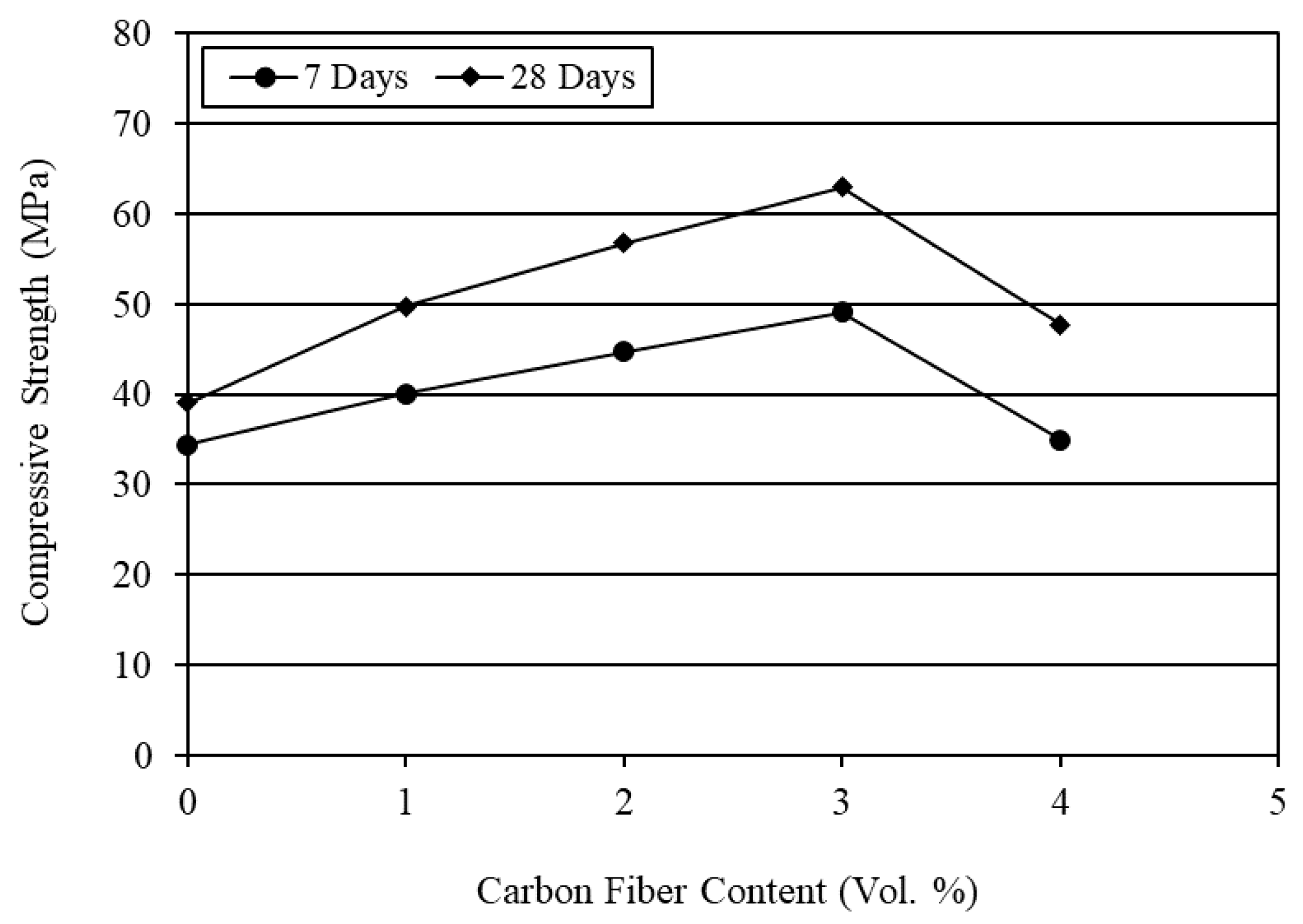
4.2. Compressive Strength
The average compression test results are given in Table 4. The effect of different carbon fiber contents on the compressive strength of mortar is presented in Figure 1. It is evident from Figure 1 that the compressive strength increased linearly with the incorporation of carbon fibers up to 3% fiber content, and then decreased sharply. Ohama et al. [41] obtained a similar trend of results for carbon fiber reinforced cement composites. In their study, the compressive strength also dropped beyond 3% fiber content. This suggests that the effect of carbon fibers is not always conducive to the compressive strength of mortar composite. It largely depends on the workability, degree of compaction, density, and entrapped air content of mortar. Even if the fibers increase the compressive strength, it is relatively low, as compared to the increases in splitting tensile strength and flexural strength. This is because the fibers cannot resist compressive load as effectively as they endure tensile and flexural loads.
The strengthening factors of various CFRM composites for compression were found after dividing their compressive strength values by the compressive strength of NPCM and are shown in Table 4. It can be seen from Table 4 that 3% carbon fibers provided the maximum increase in compressive strength and the extent of strengthening was 61% at the age of 28 days. The wet density and entrapped air content results of the CFRM composite with 3% carbon fibers were linked with its highest compressive strength. In general, the rise in density and the reduction in entrapped air content increased the compressive strength. In contrast, the CFRM composite with 4% carbon fibers content (CFRM4) had a relatively low compressive strength; the strengthening factor for this mortar composite was about 22%, as evident from Table 4. The main reason for the lower compressive strength of CFRM4 is that the degree of compaction was not good because of the poor workability. Therefore, excessive air bubbles remained entrapped within the mix (refer to Table 3) and the density decreased, which eventually caused a negative effect on the compressive strength of mortar composite.
The reduction in the compressive strength of mortar for more than 3% carbon fibers can also be due to the retarding effect of superplasticizer as observed by Pigeon et al. [42]. Since a relatively high dosage of superplasticizer was used in the mix with 4% carbon fibers, it may alter the composition of calcium silicate hydrate (CSH, a strength-contributing hydration product) and retard the hydration of cement significantly, thus reducing the compressive strength of mortar. The overall results suggest that carbon fibers can improve the compressive strength of mortar if used with a volume content that does not cause any adverse effect on its workability and entrap excessive air bubbles inside the mix.
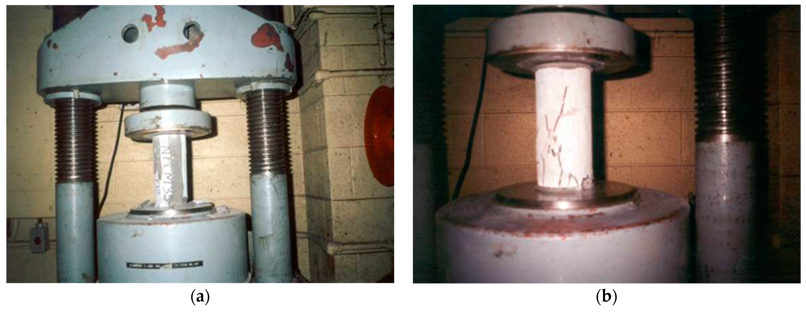
The ductility of mortar was much increased by carbon fibers, as reveled from the failure modes of different cylindrical specimens in compression test. NPCM exhibited a brittle failure as shown in Figure 2a. On the other hand, CFRM composite at first yielded and then progressively cracked as shown in Figure 2b. The standard compression test under uniaxial loading produced a combination of shear failure near the ends with lateral swelling and cracking in the central portion of the specimen. It suggests that the fibers had a reinforcing effect in the lateral direction. However, this effect was predominant in the CFRM composites with 3% and 4% fiber contents. It indicates that the fiber content has a significant influence on the lateral strain capacity and thereby on the ductility of CFRM composite.
The increase in ductility as observed during the compression test was largely due to the increased resistance of carbon fibers against the growth of cracks. The resistance to crack propagation increased with a greater fiber content. Therefore, the improvement in ductility was significant with a greater fiber content. Shah and Chandra [43] showed that the volume of compressed concrete starts to dilate under loading, and this dilation is related to the slow growth of microcracks within the cement composite. The incorporation of carbon fibers in the cement mortar delayed and reduced the volume dilation. As a result, the improved ductility behavior of CFRM composite was noticed in the cylinder specimens under compression test.
4.3. Splitting Tensile Strength
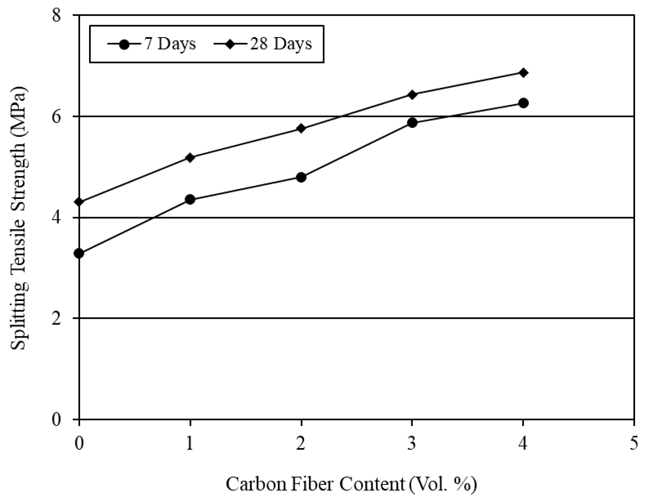
The average results of splitting tension test are given in Table 5. The effect of different carbon fiber contents on the splitting tensile strength of mortar composite is presented in Figure 3. It is obvious from Figure 3 that the splitting tensile strength of CFRM composite increased almost linearly with the increase in carbon fiber content. A similar trend of increase in tensile strength was reported in several past studies [5,30,44,45,46].
The strengthening factors of various CFRM composites for tension were found after dividing their tensile strength by the tensile strength of NPCM and are shown in Table 5. It is evident from Table 5 that the splitting tensile strength of CFRM composite at 4% carbon fibers was 1.5 to 2 times greater than that of NPCM. This increase in tensile strength is due to the bridging action of carbon fibers during crack formation. However, the increase in tensile strength was less compared with the findings of other researchers who conducted direct tension test using dumbbell specimens [14,46]. The splitting tension test was conducted in the present study to determine the tensile strength of CFRM composite. Neville [47] mentioned that the splitting tension test yields a lower value of tensile strength in the case of mortar. This is perhaps due to the absence of large particles such as coarse aggregates near the surface onto which the load is applied. In addition, it can be seen from Table 5 that the rate of increase in splitting tensile strength was greater at the age of 7 days although the maximum tensile strength was obtained at 28 days. This is because the gain in tensile strength is usually high at early ages due to a higher degree of cement hydration, which slows down at later ages.
The increase in tensile strength is not attributed to the incorporation of carbon fibers alone. It does not only depend on the volume content of carbon fibers but also on the interfacial bond between the constituents. Katz et al. [48] and Park et al. [14] reported that the densification of the matrix surrounding carbon fibers improves their interfacial bond with the other solid ingredients of mortar and thereby enhances the pull-out strength of the fibers. The presence of silica fume in CFRM composite results in a densification of the matrix around carbon fibers and therefore the contact area between fibers and adjacent materials is increased and a stronger bond is established. The interfacial bond is also strengthened by additional CSH formed from the pozzolanic reaction between silica fume and calcium hydroxide (Ca(OH)2), which is liberated during cement hydration [12]. The interlocking of sand particles and carbon fibers can also improve the interfacial bond; furthermore, some of the fine cement grains and finer silica fume particles might penetrate the holes or surface grooves existing on the carbon fibers; consequently, the surface roughness of fibers increases and therefore the bond between carbon fibers and matrix can be enhanced [1]. All these effects might eventually lead to a greater improvement in the tensile strength of CFRM composite.
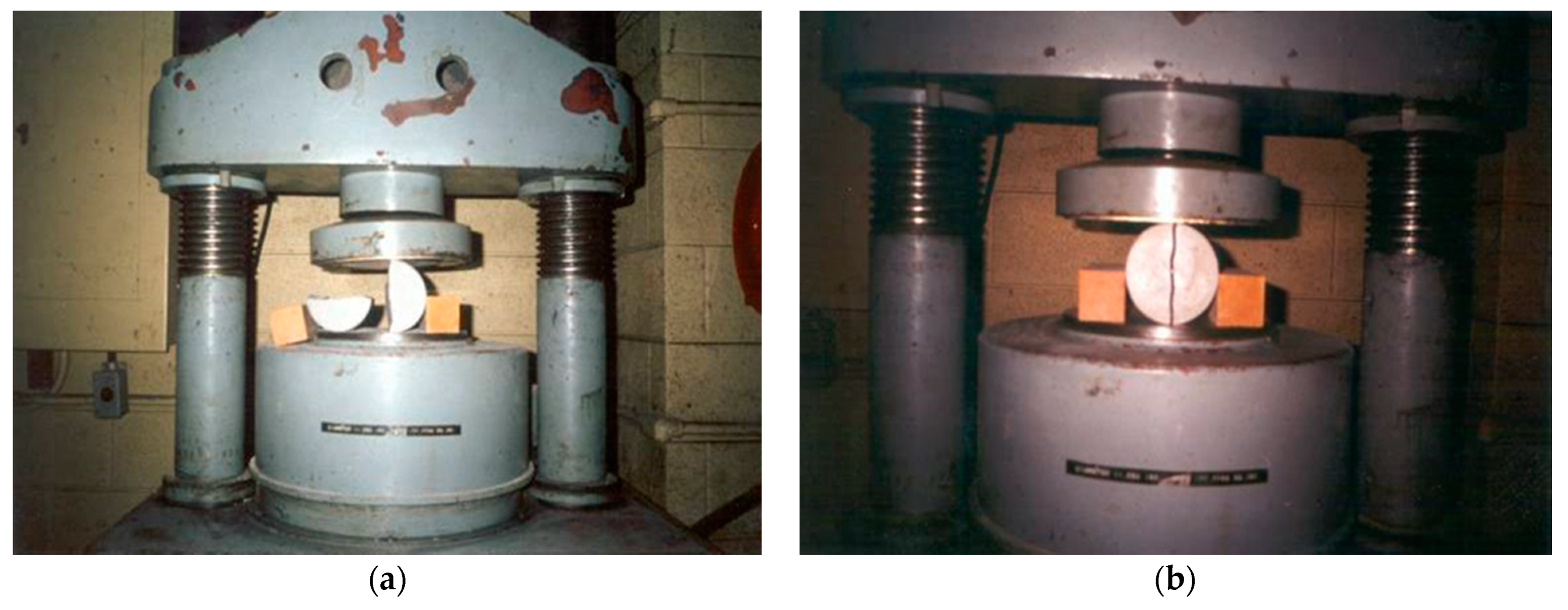
The ductile behavior of CFRM composite was also observed in the cylinder specimens under splitting tension test. The failure modes for NPCM and CFRM composites are shown in Figure 4. The cylinder specimens used in the splitting tension test of NPCM failed suddenly. The failure mode was brittle, and the cylinders were completely split as shown in Figure 4a. Conversely, the failure mode for the cylinders used in the splitting tension test of CFRM composites was ductile under the applied load. This was evidenced by the increased ability of the cylinders to deform markedly under the applied load without splitting. The cylinder specimens failed showing a visible vertical crack throughout the axis but did not fall apart, as obvious from Figure 4b.
4.4. Flexural Strength
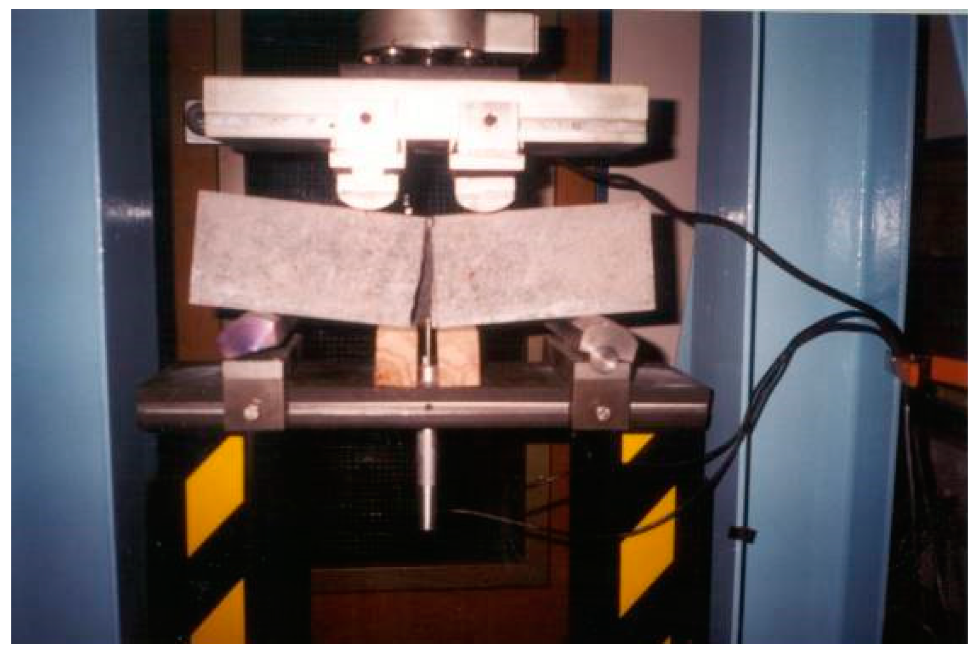
The flexure test was conducted by third-point loading arrangement as shown in Figure 5. The third-point loading test usually gives more reliable results. This is because the probability of a weak element being subjected to the critical stress is considerably greater under two third-point loads [47]. In third-point loading, the middle-third of the beam is subjected to the maximum bending stress. Therefore, the critical crack may appear at any section within the middle third or it could start in the middle third and then extend to one of the two end-thirds of the beam. In the present study, all specimens failed with a fracture occurring completely within the middle third of the beams; such an example is shown in Figure 5. This indicates that the bottom face of the middle third of the beam experienced the maximum bending stress.
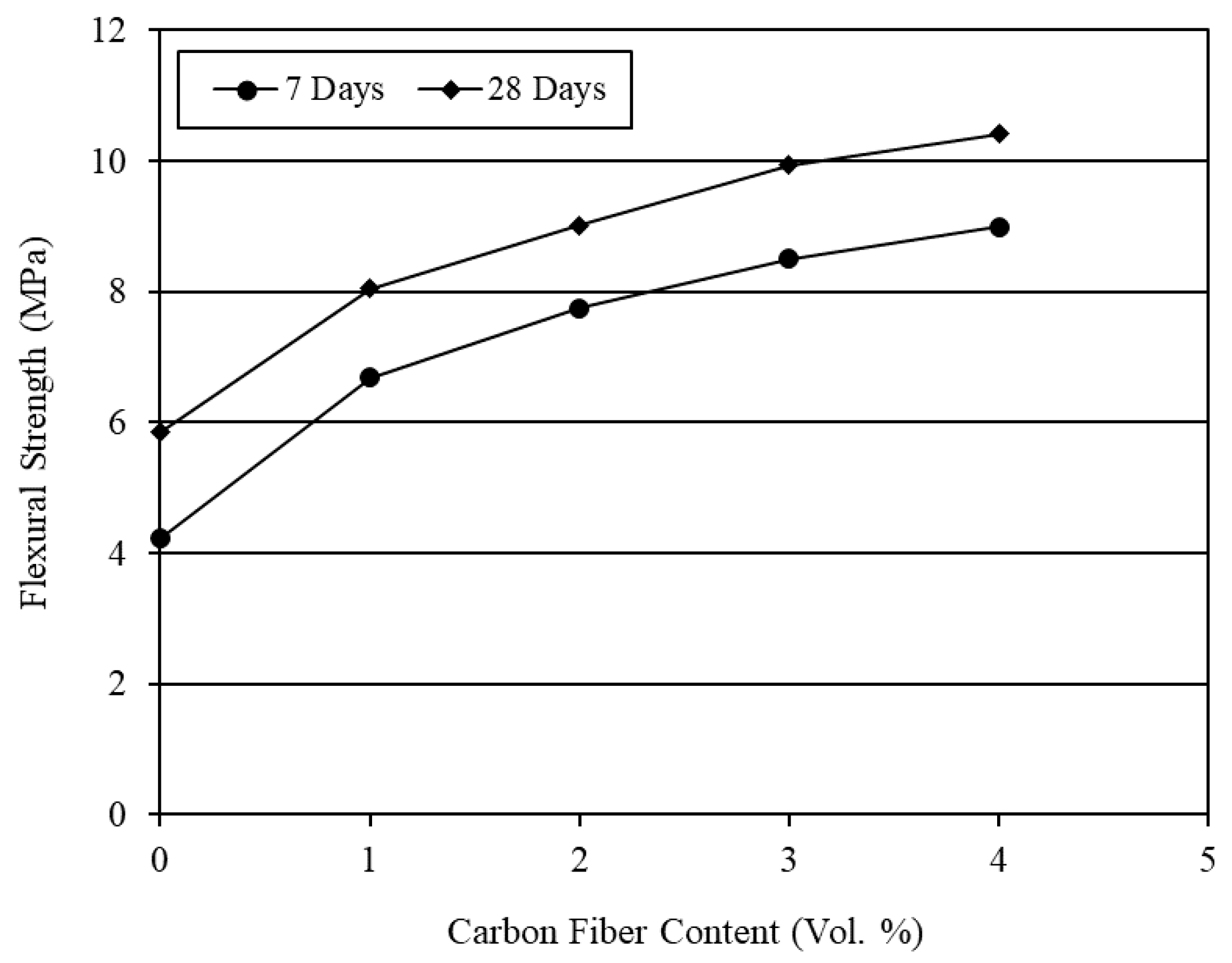
The average flexure test results are given in Table 6. The effect of carbon fibers is graphically presented in Figure 6. It is obvious from Figure 6 that the flexural strength of CFRM composite increased non-linearly with the increase in carbon fiber content. A similar trend was observed in several earlier studies [8,26,29,44,46].
The strengthening factors of various CFRM composites for flexure were obtained after dividing their flexural strength values by the flexural strength of NPCM and are shown in Table 6. The incorporation of carbon fibers significantly increased the flexural strength of CFRM composite. It is also obvious from Table 6 that the strengthening factors were greater at 7 days, although the highest level of flexural strength was obtained at the age of 28 days. The mortar composite containing 4% carbon fibers provided the maximum flexural strength. In general, about a two-fold increase in flexural strength was observed for the carbon fibers at 4% volume content. The increase in flexural strength with the incorporation of carbon fibers is mainly due to the increased reinforcing and bonding effects of fibers resulting from the densified microstructure of mortar brought by silica fume and superplasticizer.
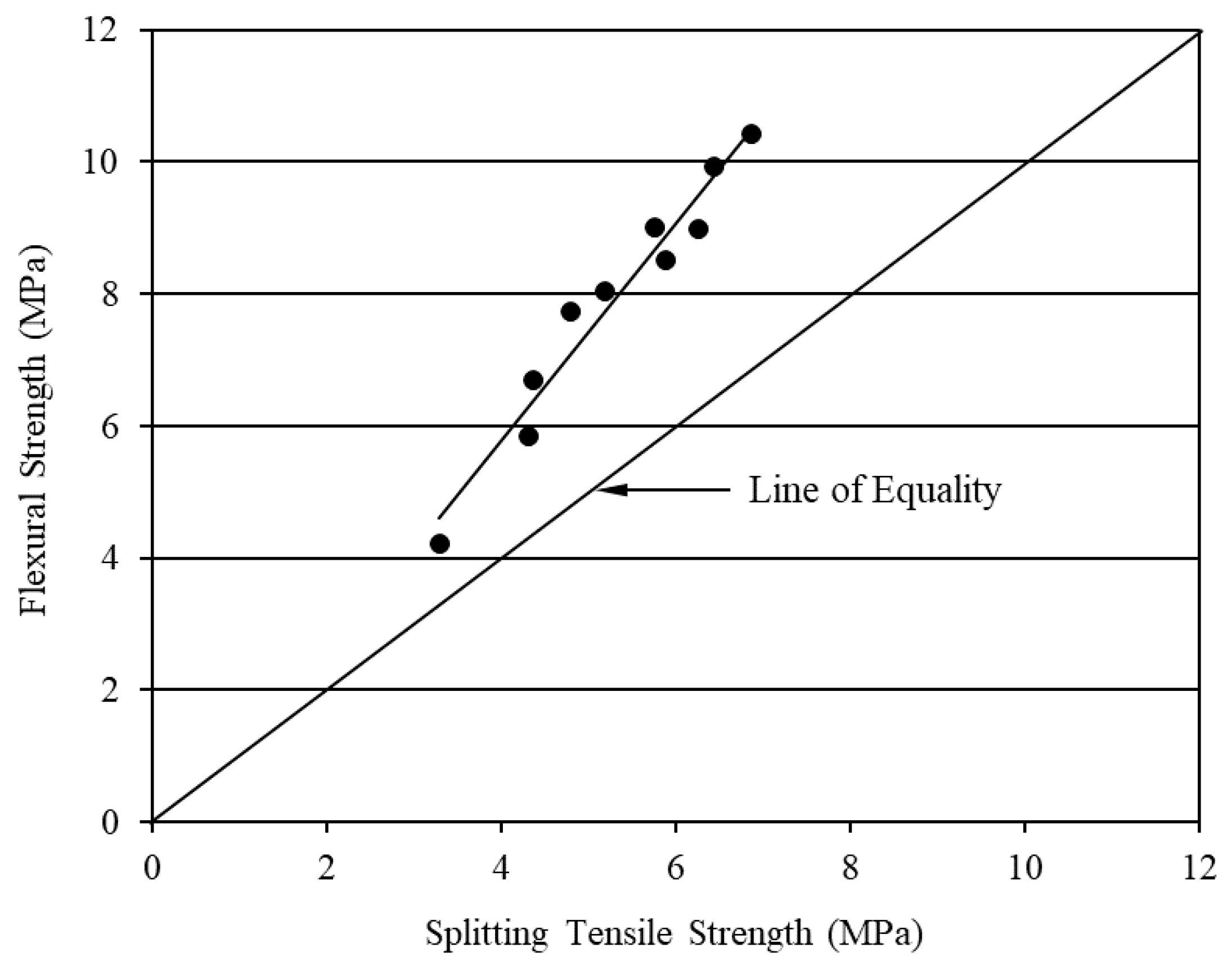
The flexural strength of CFRM composite was much higher than its splitting tensile strength, as evident from Figure 7. This is due to the disparity in the orientation of carbon fibers in test specimens. Sakai et al. [49] reported that carbon fibers tend to be oriented at right angle to the vibrational direction of a vibrator used during molding. However, this tendency is expected to be affected by the dimensions of the specimen. The compaction by vibration induced a degree of preferential 2D-fiber orientation parallel to the length of beam specimens, which were used for the flexure test. This was also evidenced by the presence of carbon fibers oriented at right angle to the fracture faces of the beam. Thus, the fiber orientation coincided with the direction of the major tensile stress and resulted in a greater flexural strength. On the other hand, the carbon fibers were oriented in a 3D-random fashion in the cylinder specimens used for the splitting tension test. This was confirmed as some of the carbon fibers were observed lying on the fracture (split) faces of the cylinder. Perhaps, the lower dimension (diameter) of the cylinder specimens lying in the horizontal plane during molding hindered the orientation of carbon fibers in a direction perpendicular to the pathway of vibration. Consequently, the reinforcing effectiveness of carbon fibers in the cylinder specimens was comparatively low towards the direction of the major tensile stress. Therefore, the lower values of splitting tensile strength were obtained for the mortar composites as compared to their flexural strength.
The assumption of linear stress distribution in the beam specimens is another reason for the higher flexural strength of CFRM composites compared with their splitting tensile strength [1]. The flexural strength was calculated based on the elastic beam theory, in which the stress–strain relation is assumed to be linear. It implies that the ultimate flexural stress in the beam specimens is supposed to be proportional to the distance from its neutral axis. However, the linear stress–strain relation is no longer valid when the first crack appears. Therefore, the actual stress block between the first-crack and maximum loads becomes parabolic instead of being triangular. Thus, the ultimate flexural strength was overestimated because of the assumption of linear stress distribution. Furthermore, the maximum fiber stress reached in the flexure test may be higher than that in the splitting tension test because the fibers and other less-stressed materials near to the neutral axis of the beam specimen hinder the propagation of cracks. In particular, the carbon fibers aligned in the direction of the major tensile stress effectively slow down the formation of the first crack, impede the propagation of cracks, and thus delay the failure of test specimen. As a result, the ultimate flexural strength becomes greater than the splitting tensile strength.
4.5. Water Absorption
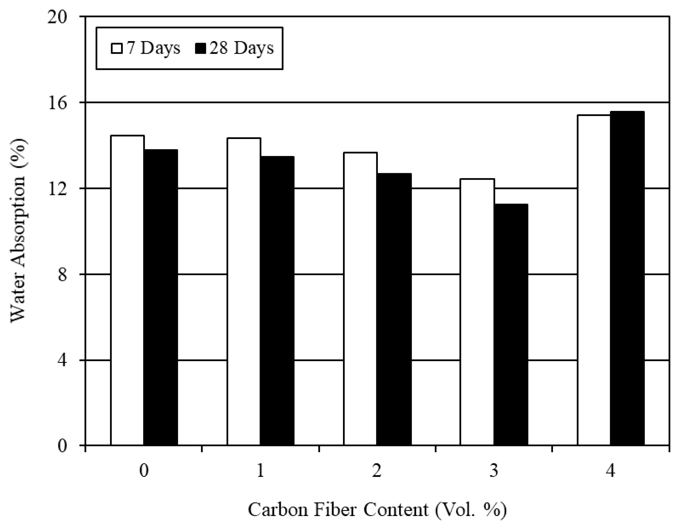
The average test results for water absorption are given in Table 7. The effect of carbon fiber content is shown in Figure 8. It can be seen from Figure 8 that the water absorption decreased with the incorporation of carbon fibers up to 3% fiber content, and then increased at 4% fiber content. Very few studies have been carried out to examine the water absorption of CFRM composite. Ohama et al. [41] performed the water absorption test for carbon fiber reinforced cement composite and found that the water absorption tends to decrease with increasing carbon fiber content up to 5%. In the present study, a reduction in the water absorption was observed for the mortar composites including 1–3% carbon fiber contents. In contrast, the water absorption of the CFRM composite with 4% carbon fibers was relatively high, as obvious from Figure 8.
The water resistance factors of various CFRM composites were found after dividing the water absorption of NPCM by the water absorption of each CFRM and are shown in Table 7. It is evident from Table 7 that the resistance to water absorption increased considerably at 3% carbon fiber content. On the contrary, the resistance to water absorption decreased for 4% carbon fiber content. This can be due to the increased number of capillary pores and air-voids existing in the mortar composite as realized from the test results of wet density and entrapped air content. The porosity largely governs the water absorption of mortar—the larger the porosity, the greater the water absorption. The density and entrapped air content results imply that the CFRM composite with 3% carbon fiber had lesser capillary pores and air-voids due to a higher degree of compaction at adequate workability. Hence, it provided the highest resistance to water absorption. Moreover, the water resistance factor at 28 days was higher than that at 7 days. This is because more CSH resulting from cement hydration and pozzolanic reaction filled in the capillary pores further, thus decreasing the porosity of mortar composite at 28 days.
The use of superplasticizer and silica fume in CFRM composite decreased the number of capillary pores in its matrix. Superplasticizer substantially decreases the water content and thus diminishes the overall porosity of mortar. It also reduces bleeding and thus assures a better adhesion among sand particles, carbon fibers, and cement paste. Moreover, silica fume contributes to reduce the porosity of mortar composite. It also improves the interfaces of sand particles and carbon fibers. However, all these improvements largely depend on the workability and degree of compaction. Workability and compaction play important roles in reducing the capillary pores and air-voids in mortar. As the mortar composite with 3% carbon fibers possessed adequate workability, the fresh mortar became well-compacted under vibration. Accordingly, the water absorption of the hardened mortar composite incorporating 3% carbon fibers decreased. Conversely, excessive capillary pores and air-voids were present in the mortar composite with 4% carbon fibers as it was too stiff in the fresh state for easy placing and sufficient compaction due to the poor workability. As a result, the maximum water absorption was obtained for CFRM4.
5. Optimum Fiber Content and Best Mortar Composite
The best mortar composite was derived by judging the overall performance in terms of workability (slump), wet density, entrapped air content, compressive strength, splitting tensile strength, flexural strength, and water absorption. The mortar composite with 3% carbon fibers (CFRM3) provided adequate slump for placing and compaction by vibration, had lower entrapped air content and higher wet density, gave the maximum compressive strength, possessed excellent splitting tensile strength and flexural strength, and offered reduced water absorption thus exhibiting the potential for excellent durability, compared with the other mortars incorporating 1%, 2%, and 4% carbon fibers. Therefore, the optimum content of carbon fibers was 3% and CFRM3 can be considered as the best mortar composite in the context of the present study.
6. Conclusions
The following conclusions are drawn based on the findings from the present study on CFRM composite.
- The workability of mortar composite decreased with higher content of carbon fibers due to large surface area and interlocking of the fibers; consequently, the entrapped air content of CFRM composite was greater and therefore its wet density became lower than that of NPCM.
- The compressive strength of mortar composite increased with the incorporation of carbon fibers when the fresh mortar was sufficiently workable and well-compacted; CFRM3 with 3% carbon fibers possessed the maximum level of compressive strength.
- The splitting tensile strength and flexural strength of mortar composite increased significantly with higher content of carbon fibers due to their greater resistance to cracking and improved bond with the other solid constituents of the mortar.
- Considerable strengthening was possible by reinforcing the cement mortar matrix with short pitch-based carbon fibers as they bridged the microcracks, resisted the propagation of these tiny cracks, and impeded the formation of macrocracks.
- The incorporation of carbon fibers diminished the water absorption and thus enhanced the durability of mortar when a sufficient workability was maintained for good compaction.
- The mortar composite with 3% carbon fibers can be considered as the optimum CFRM composite based on its performance with respect to workability, wet density, entrapped air content, compressive strength, splitting tensile strength, flexural strength, and water absorption.
Author Contributions
Conceptualization, M.S., G.A.-S. and N.H.; data curation, M.S.; formal analysis, M.S.; funding acquisition, M.S., G.A.-S. and N.H.; investigation, M.S.; methodology, M.S., G.A.-S. and N.H.; project administration, G.A.-S. and N.H.; resources, G.A.-S. and N.H.; supervision, G.A.-S. and N.H.; validation, G.A.-S. and N.H.; visualization, M.S.; writing—original draft preparation, M.S.; writing—review and editing, M.S., G.A.-S. and N.H. All authors have read and agreed to the published version of the manuscript.
Funding
This research received no external funding.
Institutional Review Board Statement
Not applicable.
Informed Consent Statement
Not applicable.
Data Availability Statement
The data presented in this study are not publicly available. The data were gathered by the first author (Md. Safiuddin) through experimental investigation.
Acknowledgments
The authors acknowledge sincere cooperation and financial support received from the Department of Civil and Environmental Engineering at the University of Windsor, Windsor, Ontario, Canada. In addition, the authors express their heartfelt gratitude to Master Builders Technologies, Brampton, Ontario, Canada for supplying silica fume and superplasticizer required for the experimental investigation.
Conflicts of Interest
The authors declare no conflict of interest.
References
- Safiuddin, M.; Abdel-Sayed, G.; Hearn, H. High Performance Mortars with Short Carbon Fibers: Properties and Mix Optimization; Lambert Academic Publishing AG & Co. KG: Saarbrücken, Germany, 2010. [Google Scholar]
- Betterman, L.R.; Ouyang, C.; Shah, S.P. Fiber-mortar interaction in microfiber-reinforced mortar. Adv. Cem. Based Mater. 1995, 2, 53–61. [Google Scholar] [CrossRef]
- Dinh, N.H.; Park, S.-H.; Choi, K.-K. Effect of dispersed micro-fibers on tensile behavior of uncoated carbon textile-reinforced cementitious mortar after high-temperature exposure. Cem. Concr. Compos. 2021, 118, 103949. [Google Scholar] [CrossRef]
- Du, Q.; Cai, C.; Lv, J.; Wu, J.; Pan, T.; Zhou, J. Experimental investigation on the mechanical properties and microstructure of basalt fiber reinforced engineered cementitious composite. Materials 2020, 13, 3796. [Google Scholar] [CrossRef]
- Graham, R.K.; Huang, B.; Shu, X.; Burdette, E.G. Laboratory evaluation of tensile strength and energy absorbing properties of cement mortar reinforced with micro- and meso-sized carbon fibers. Construct. Build. Mater. 2013, 44, 751–756. [Google Scholar] [CrossRef]
- Pierre, P.; Pleau, R.; Pigeon, M. Mechanical properties of steel microfiber reinforced pastes and mortars. J. Mater. Civ. Eng. 1999, 11, 317–324. [Google Scholar] [CrossRef]
- Soroushian, P.; Khan, A.; Hsu, J.W. Mechanical properties of concrete materials reinforced with polypropylene or polyethylene fibers. ACI Mater. J. 1992, 89, 535–540. [Google Scholar]
- Banthia, N.; Sheng, J. Strength and toughness of cement mortars reinforced with micro-fibers of carbon, steel, and polypropylene. In Proceedings of the Second Canadian Symposium on Cement and Concrete, University of British Columbia, Vancouver, BC, Canada, 24–26 July 1991; pp. 75–83. [Google Scholar]
- Etbridge, M.D.; Krifa, M. Renewed focus on short fibers. In Textile Topics; International Textile Center, Texas Tech University: Lubbock, TX, USA, 2004; Volume 2004-3. [Google Scholar]
- George, M.; Sathyan, D.; Mini, K.M. Investigations on effect of different fibers on the properties of engineered cementitious composites. Mater. Today Proc. 2021, 42, 1417–1421. [Google Scholar] [CrossRef]
- Deng, M.; Dong, Z.; Zhang, C. Experimental investigation on tensile behavior of carbon textile reinforced mortar (TRM) added with short polyvinyl alcohol (PVA) fibers. Construct. Build. Mater. 2020, 235, 117801. [Google Scholar] [CrossRef]
- Safiuddin, M.; Yakhlaf, M.; Soudki, K.A. Key mechanical properties and microstructure of carbon fibre reinforced self-consolidating concrete. Construct. Build. Mater. 2018, 164, 477–488. [Google Scholar] [CrossRef]
- Toutanji, H.A.; El-Korchi, T.; Katz, R.N. Strength and reliability of carbon-fiber reinforced cement composites. Cem. Concr. Compos. 1994, 2, 15–21. [Google Scholar] [CrossRef]
- Park, S.B.; Lee, B.I.; Lim, Y.S. Experimental study on the engineering properties of carbon fiber reinforced cement composites. Cem. Concr. Res. 1991, 21, 589–600. [Google Scholar] [CrossRef]
- Marikunte, S.; Shah, S.P. High performance cement-based composites for the future. In Fiber Reinforced Concrete: Modern Developments; The University of British Columbia: Vancouver, BC, Canada, 1995; pp. 13–27. [Google Scholar]
- Gilson, J.C. Health hazards of asbestos. Compos. 1972, 3, 57–59. [Google Scholar] [CrossRef]
- Bentur, A. Mechanisms of potential embrittlement and strength loss of glass fiber reinforced cement composites. In Proceedings of the Symposium on Durability of Glass Fiber Reinforced Cement Concrete, Precast/Prestressed Concrete Institute, Chicago, IL, USA, 12–15 November 1985; pp. 109–123. [Google Scholar]
- Soroushian, P.; Marikunte, S. Cellulose fiber reinforced cement composites: State-of-the-art. In Proceedings of the First Canadian University/Industry Workshop on Fibre Reinforced Concrete, Québec, BC, Canada, 28–29 October 1991; pp. 44–58. [Google Scholar]
- ACI 544. 1R-96 (Reapproved 2002). Report on Fiber Reinforced Concrete; American Concrete Institute: Detroit, MI, USA, 2002. [Google Scholar]
- Banthia, N. Pitch-based carbon fiber reinforced cements: Structure, performance, applications and research needs. Can. J. Civ. Eng. 1992, 19, 26–38. [Google Scholar] [CrossRef]
- Ali, M.A.; Majumder, A.J.; Rayment, D.L. Carbon fiber reinforcement of cement. Cem. Concr. Res. 1972, 2, 201–212. [Google Scholar] [CrossRef]
- Wang, L.; He, T.; Zhou, Y.; Tang, S.; Tan, J.; Liu, Z.; Su, J. The influence of fiber type and length on the cracking resistance, durability and pore structure of face slab concrete. Construct. Build. Mater. 2021, 282, 122706. [Google Scholar] [CrossRef]
- Akihama, S.; Suenaga, T.; Nakagawa, H. Carbon fiber reinforced concrete. Concr. Int. 1988, 10, 40–47. [Google Scholar] [CrossRef]
- Morgan, D.R.; Razaqpur, A.G.; Crimi, J. Fibre reinforced concrete products. In Advanced Composite Materials in Bridges & Structures; Canadian Society for Civil Engineering: Montreal, QC, Canada, 1992; pp. 18–32. [Google Scholar]
- Banthia, N.; Genois, I. Pitch-based carbon fiber reinforced cement composites. In Fiber Reinforced Concrete: Modern Developments; The University of British Columbia: Vancouver, QC, Canada, 1995; pp. 213–228. [Google Scholar]
- Donnini, J.; Bellezze, T.; Corinaldesi, V. Mechanical, electrical and self-sensing properties of cementitious mortars containing short carbon fibers. J. Build. Eng. 2018, 20, 8–14. [Google Scholar] [CrossRef]
- Niu, M.; Zhang, J.; Li, G.; Song, Z.; Wang, X. Mechanical properties of polyvinyl alcohol fiber-reinforced sulfoaluminate cement mortar containing high-volume of fly ash. J. Build. Eng. 2021, 35, 101988. [Google Scholar] [CrossRef]
- Vipulanandan, C.; Garas, V. Electrical resistivity, pulse velocity, and compressive properties of carbon fiber-reinforced cement mortar. J. Mater. Civ. Eng. 2008, 20, 93–101. [Google Scholar] [CrossRef]
- Li, Y.-F.; Lee, K.-F.; Ramanathan, G.K.; Cheng, T.-W.; Huang, C.-H.; Tsai, Y.-K. Static and dynamic performances of chopped carbon-fiber-reinforced mortar and concrete incorporated with disparate lengths. Materials 2021, 14, 972. [Google Scholar] [CrossRef]
- Zhang, X.; Ge, L.; Zhang, Y.; Wang, J. Mechanical properties of carbon-fiber RPC and design method of carbon-fiber content under different curing systems. Materials 2019, 12, 3759. [Google Scholar] [CrossRef] [PubMed] [Green Version]
- <named-content content-type="background:white">Liu, D.J.; Chen, M.J.; Xue, L.; He, F.; Hu, J. The effect of the carbon fiber on concrete compressive strength. Adv. Mater. Res. 2018, 1145, 106–111. [Google Scholar]
- ASTM C150-07. Standard Specification for Portland Cement; ASTM International: West Conshohocken, PA, USA, 2007. [Google Scholar]
- ASTM C1240-05. Standard Specification for Use of Silica Fume as a Mineral Admixture in Hydraulic Cement Concrete, Mortar, and Grout; ASTM International: West Conshohocken, PA, USA, 2005. [Google Scholar]
- Safiuddin, M.; Abdel-Sayed, G.; Hearn, N. Effects of pitch-based short carbon fibers on the workability, unit weight, and air content of mortar composite. Fibers 2018, 6, 63. [Google Scholar] [CrossRef] [Green Version]
- ASTM C192/C192M-06. Standard Practice for Making and Curing Concrete Test Specimens in the Laboratory; ASTM International: West Conshohocken, PA, USA, 2006. [Google Scholar]
- ASTM C39/C39M-01. Standard Test Method for Compressive Strength of Cylindrical Concrete Specimens; ASTM International: West Conshohocken, PA, USA, 2001. [Google Scholar]
- ASTM C617-98 (Reapproved 2003). Standard Practice for Capping Cylindrical Concrete Specimens; ASTM International: West Conshohocken, PA, USA, 2003. [Google Scholar]
- ASTM C496/C496M-04. Standard Test Method for Splitting Tensile Strength of Cylindrical Concrete Specimens; ASTM International: West Conshohocken, PA, USA, 2004. [Google Scholar]
- ASTM C1018-97. Standard Test Method for Flexural Toughness and First-Crack Strength of Fiber-Reinforced Concrete (Using Beam with Third-Point Loading); ASTM International: West Conshohocken, PA, USA, 1998. [Google Scholar]
- ASTM C1195-03. Standard Test Method for Absorption of Architectural Cast Stone; ASTM International: West Conshohocken, PA, USA, 2003. [Google Scholar]
- Ohama, Y.; Amano, M.; Endo, M. Properties of carbon fiber reinforced cement with silica fume. Concr. Int. 1985, 7, 58–62. [Google Scholar]
- Pigeon, M.; Pleau, R.; Azzabi, M.; Banthia, N. Durability of microfiber reinforced mortars. Cem. Concr. Res. 1996, 26, 601–609. [Google Scholar] [CrossRef]
- Shah, S.P.; Chandra, S. Critical stress, volume change, and microcracking of concrete. ACI J. Proc. 1968, 65, 770–781. [Google Scholar]
- Kim, T.-J.; Park, C.-K. Flexural and tensile strength developments of various shape carbon fiber-reinforced lightweight cementitious composites. Cem. Concr. Res. 1998, 28, 955–960. [Google Scholar] [CrossRef]
- Zheng, Q.; Chung, D.D.L. Carbon fiber reinforced cement composites improved by using chemical agents. Cem. Concr. Res. 1989, 19, 25–41. [Google Scholar] [CrossRef]
- Akihama, S.; Suenaga, T.; Banno, T. Mechanical properties of carbon fiber reinforced cement composites. Int. J. Cem. Compos. Lightweight Concr. 1986, 8, 21–33. [Google Scholar] [CrossRef]
- Neville, A.M. Properties of Concrete, Fourth Edition; John Wiley & Sons Inc.: New York, NY, USA, 1996. [Google Scholar]
- Katz, A.; Li, V.C.; Kazmer, A. Bond properties of carbon fibers in cementitious matrix. J. Mater. Civ. Eng. 1995, 7, 125–128. [Google Scholar] [CrossRef] [Green Version]
- Sakai, H.; Takahashi, K.; Mitsui, Y.; Ando, T.; Awata, M.; Hoshijima, T. Flexural behavior of carbon fiber reinforced cement composite. In Fiber Reinforced Concrete: Developments and Innovations; ACI SP-142; American Concrete Institute: Detroit, MI, USA, 1994; pp. 73–89. [Google Scholar]
Figure 1.
Effect of carbon fiber content on the compressive strength of mortar composite.

Figure 2.
Failure mode of the specimens in compression test—(a) NPCM and (b) CFRM.

Figure 3.
Effect of carbon fiber content on the splitting tensile strength of mortar composite.

Figure 4.
Failure mode of the specimens in splitting tension test—(a) NPCM and (b) CFRM.

Figure 5.
Failure mode of the specimen in flexure test.

Figure 6.
Effect of carbon fiber content on the flexural strength of mortar composite.

Figure 7.
Flexural strength versus splitting tensile strength of CFRM composite.

Figure 8.
Effect of carbon fiber content on the water absorption of mortar composite.


Table 1.
Typical chemical composition of normal Portland cement and silica fume.
| Normal Portland Cement | Silica Fume | ||
|---|---|---|---|
| Chemical Component | Mass Content (%) | Chemical Component | Mass Content (%) |
| Calcium oxide (CaO) | 64.5 | Silicon dioxide (SiO2) | 91.1 |
| Silicon dioxide (SiO2) | 20.0 | Aluminum oxide (Al2O3) | 1.4 |
| Aluminum oxide (Al2O3) | 5.6 | Ferric oxide (Fe2O3) | 1.2 |
| Ferric oxides (Fe2O3 and FeO) | 3.5 | Calcium oxide (CaO) | 0.4 |
| Magnesium oxide (MgO) | 2.0 | Magnesium oxide (MgO) | 0.9 |
| Sulfur trioxide (SO3) | 1.5 | Sodium oxide (Na2O) | 0.5 |
| Alkaline oxide (Na2O and K2O) | 0.9 | Potassium oxide (K2O) | 1.5 |
| Igneous loss | 2 | Igneous loss | 3.0 |
Table 2.
Mix proportions of various mortar composites.
| Type of Mortar Composite | Cement (kg/m3) | Sand (kg/m3) | Silica Fume (kg/m3) | Carbon Fiber (Vol. %) | Water (kg/m3) | SP (%B) |
|---|---|---|---|---|---|---|
| NPCM | 955.9 | 562.3 | 168.7 | 0 | 393.6 | 1 |
| CFRM1 | 917.2 | 539.6 | 161.9 | 1 | 377.7 | 2 |
| CFRM2 | 898.0 | 528.2 | 158.5 | 2 | 369.8 | 3 |
| CFRM3 | 878.6 | 516.9 | 155.1 | 3 | 361.8 | 4 |
| CFRM4 | 859.4 | 505.5 | 151.7 | 4 | 353.9 | 5 |
Table 3.
Fresh properties of various mortar composites.
| Type of Mortar Composite | Slump (cm) | Wet Density (kg/m3) | Entrapped Air Content (%) |
|---|---|---|---|
| NPCM | 26.5 | 2070.7 | 1.0 |
| CFRM1 | 19 | 1968.8 | 5.2 |
| CFRM2 | 12.5 | 1947.7 | 6.4 |
| CFRM3 | 6.5 | 1989.9 | 4.2 |
| CFRM4 | 2.5 | 1905.5 | 7.9 |
Table 4.
Compressive strength and strengthening factors of various mortar composites.
| Type of Mortar | Compressive Strength (MPa) | Strengthening Factor | ||
|---|---|---|---|---|
| 7 Days | 28 Days | 7 Days | 28 Days | |
| NPCM | 34.37 | 39.05 | 1.00 | 1.00 |
| CFRM1 | 40.04 | 49.77 | 1.15 | 1.28 |
| CFRM2 | 44.76 | 56.75 | 1.30 | 1.45 |
| CFRM3 | 49.11 | 62.99 | 1.43 | 1.61 |
| CFRM4 | 34.94 | 47.72 | 1.02 | 1.22 |
Table 5.
Splitting tensile strength and strengthening factors of various mortar composites.
| Type of Mortar | Tensile Strength (MPa) | Strengthening Factor | ||
|---|---|---|---|---|
| 7 Days | 28 Days | 7 Days | 28 Days | |
| NPCM | 3.29 | 4.31 | 1.00 | 1.00 |
| CFRM1 | 4.36 | 5.19 | 1.33 | 1.21 |
| CFRM2 | 4.80 | 5.76 | 1.46 | 1.34 |
| CFRM3 | 5.88 | 6.43 | 1.79 | 1.49 |
| CFRM4 | 6.26 | 6.87 | 1.90 | 1.59 |
Table 6.
Flexural strength and strengthening factors of various mortar composites.
| Type of Mortar | Flexural Strength (MPa) | Strengthening Factor | ||
|---|---|---|---|---|
| 7 Days | 28 Days | 7 Days | 28 Days | |
| NPCM | 4.22 | 5.85 | 1.00 | 1.00 |
| CFRM1 | 6.68 | 8.04 | 1.58 | 1.37 |
| CFRM2 | 7.74 | 9.01 | 1.83 | 1.54 |
| CFRM3 | 8.50 | 9.93 | 2.01 | 1.70 |
| CFRM4 | 8.99 | 10.41 | 2.13 | 1.78 |
Table 7.
Water absorption and water resistance factors of various mortar composites.
| Type of Mortar | Water Absorption (wt.%) | Water Resistance Factor | ||
|---|---|---|---|---|
| 7 Days | 28 Days | 7 Days | 28 Days | |
| NPCM | 14.44 | 13.80 | 1.00 | 1.00 |
| CFRM1 | 14.33 | 13.47 | 1.01 | 1.03 |
| CFRM2 | 13.67 | 12.68 | 1.06 | 1.09 |
| CFRM3 | 12.45 | 11.23 | 1.16 | 1.23 |
| CFRM4 | 15.41 | 15.56 | 0.94 | 0.89 |
Publisher’s Note: MDPI stays neutral with regard to jurisdictional claims in published maps and institutional affiliations. |
© 2021 by the authors. Licensee MDPI, Basel, Switzerland. This article is an open access article distributed under the terms and conditions of the Creative Commons Attribution (CC BY) license (https://creativecommons.org/licenses/by/4.0/).
Share and Cite
MDPI and ACS Style
Safiuddin, M.; Abdel-Sayed, G.; Hearn, N. Absorption and Strength Properties of Short Carbon Fiber Reinforced Mortar Composite. Buildings 2021, 11, 300. https://0-doi-org.brum.beds.ac.uk/10.3390/buildings11070300
AMA Style
Safiuddin M, Abdel-Sayed G, Hearn N. Absorption and Strength Properties of Short Carbon Fiber Reinforced Mortar Composite. Buildings. 2021; 11(7):300. https://0-doi-org.brum.beds.ac.uk/10.3390/buildings11070300
Chicago/Turabian StyleSafiuddin, Md., George Abdel-Sayed, and Nataliya Hearn. 2021. "Absorption and Strength Properties of Short Carbon Fiber Reinforced Mortar Composite" Buildings 11, no. 7: 300. https://0-doi-org.brum.beds.ac.uk/10.3390/buildings11070300
Note that from the first issue of 2016, this journal uses article numbers instead of page numbers. See further details here.