
Enhancing the Effectiveness of Oxygen Evolution Reaction by Electrodeposition of Transition Metal Nanoparticles on Nickel Foam Material

 ,
,  ,
,  ,
,
Abstract
:1. Introduction
2. Results and Discussion
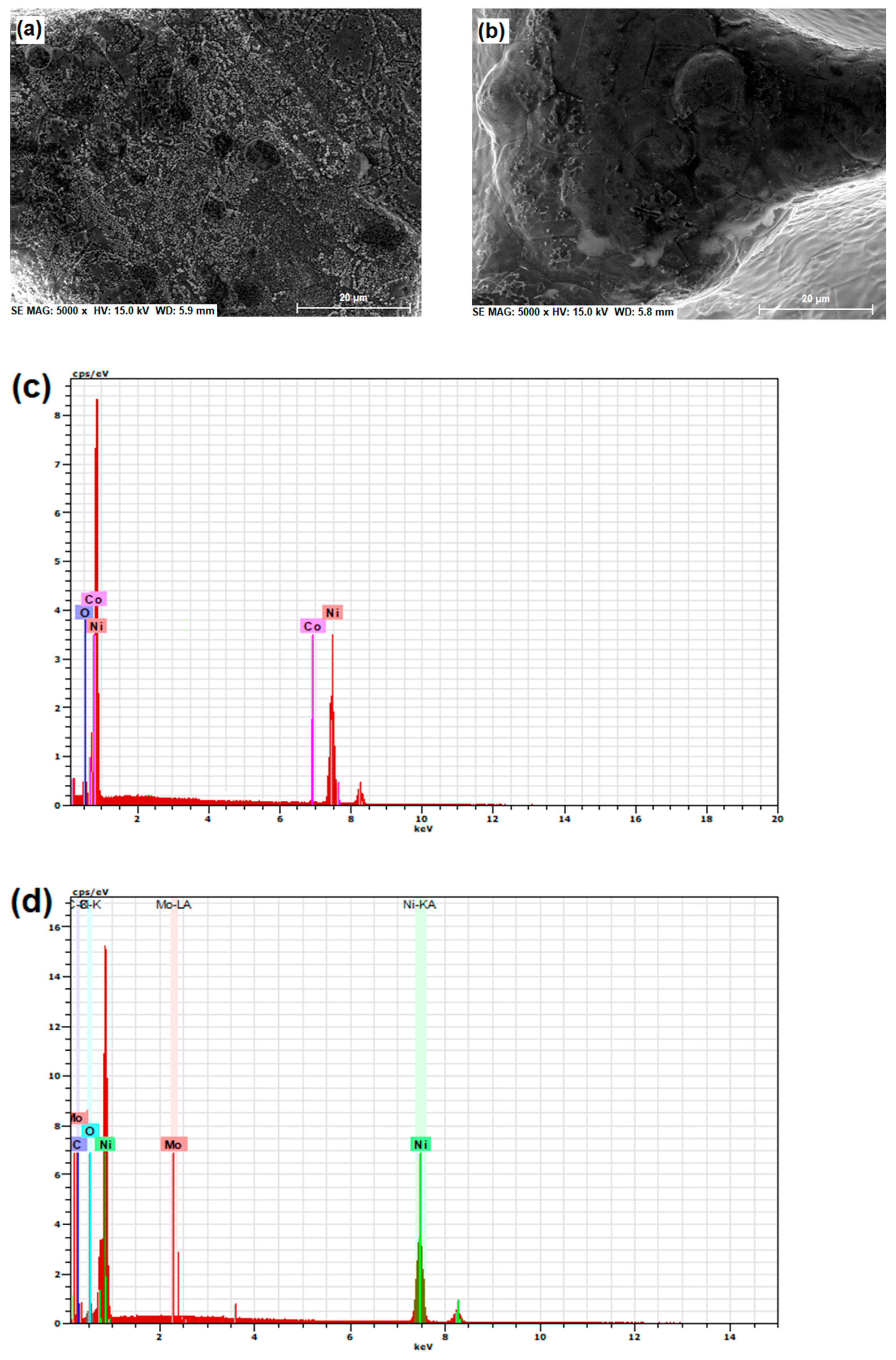
2.1. SEM/EDX Characterization of Ni Foam and Co-, and Mo-Modified Nickel Foam Electrodes
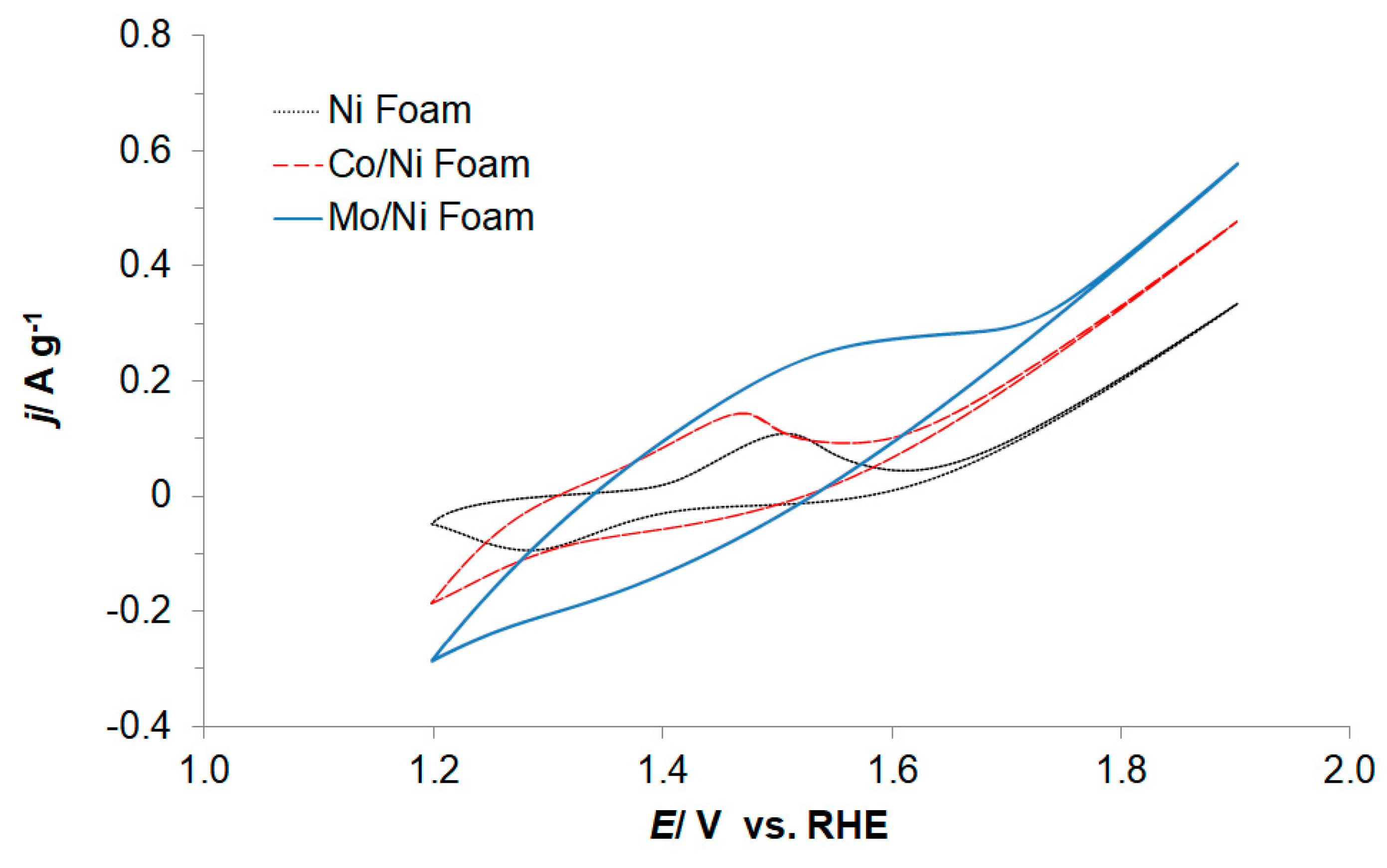
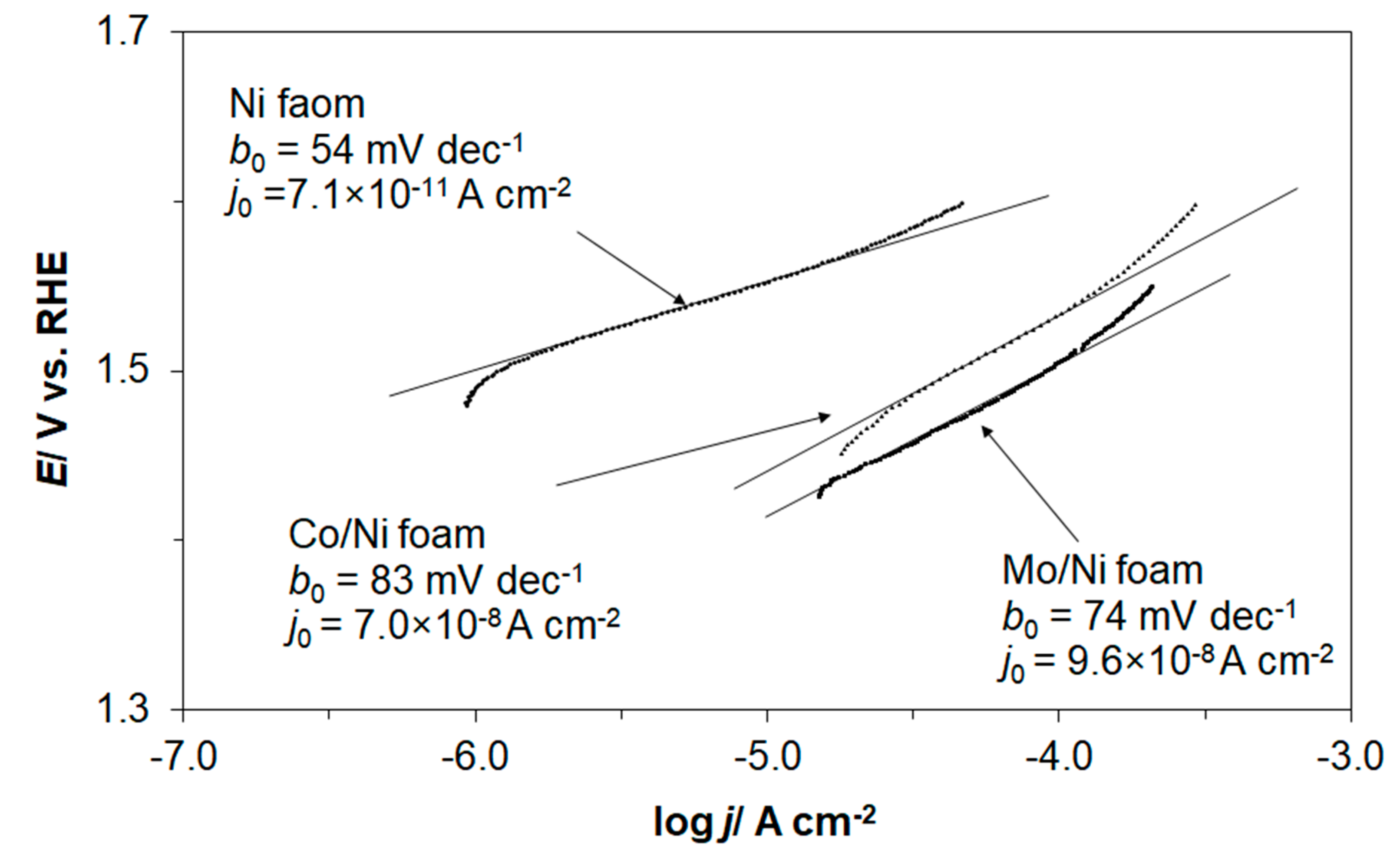
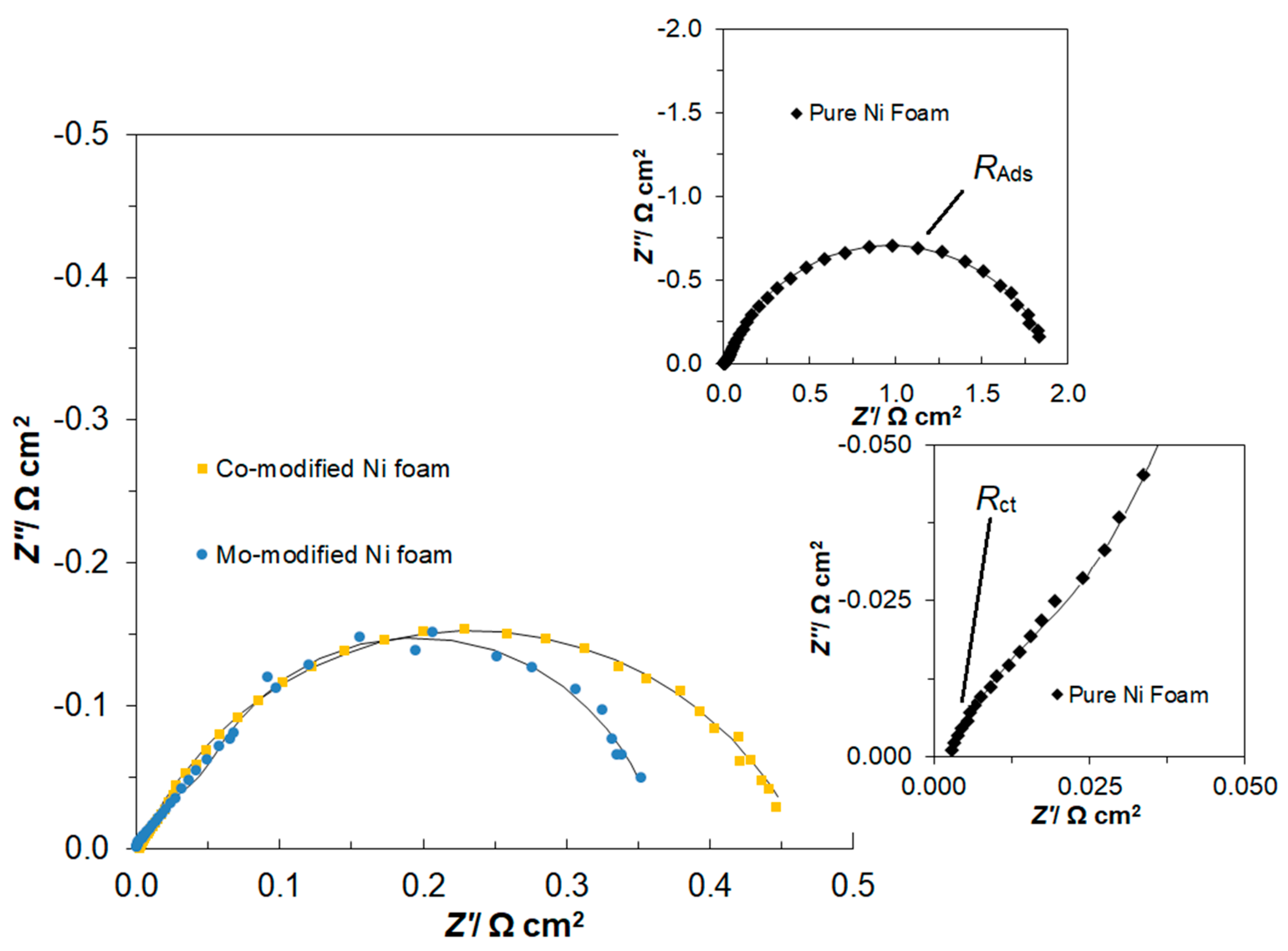
2.2. OER Characterizations of Ni Foam, Co- and Mo-Modified Ni Foam Electrodes
3. Materials and Methods
3.1. Solutions and Chemical Reagents
3.2. Preparation of Electrochemical Cell and Electrodes
3.3. Experimental Methodology
4. Conclusions
Author Contributions
Funding
Acknowledgments
Conflicts of Interest
References
- Martins, F.; Felgueiras, C.; Smitkova, M.; Caetano, N. Analysis of Fossil Fuel Energy Consumption and Environmental Impacts in European Countries. Energies 2019, 12, 964. [Google Scholar] [CrossRef] [Green Version]
- Krane, J. Climate change and fossil fuel: An examination of risks for the energy industry and producer states. MRS Energy Sustain. 2017, 4, 1–12. [Google Scholar] [CrossRef] [Green Version]
- Dorning, M.A.; Diffendorfer, J.E.; Loss, S.R.; Bagstad, K.J. Review of indicators for comparing environmental effects across energy sources. Environ. Res. Lett. 2019, 14, 103002. [Google Scholar] [CrossRef]
- Solarin, S.A. An environmental impact assessment of fossil fuel subsidies in emerging and developing economies. Environ. Impact Assess. Rev. 2020, 85, 106443. [Google Scholar] [CrossRef]
- Kåberger, T. Progress of renewable electricity replacing fossil fuels. Glob. Energy Interconnect. 2018, 1, 48–52. [Google Scholar]
- Wang, Q.; Chang, P.; Bai, R.; Liu, W.; Dai, J.; Tang, Y. Mitigation Strategy for Duck Curve in High Photovoltaic Penetration Power System Using Concentrating Solar Power Station. Energies 2019, 12, 3521. [Google Scholar] [CrossRef] [Green Version]
- Züttel, B.A.; Remhof, A.; Borgschulte, A.; Friedrichs, O. Hydrogen: The future energy carrier. Philos. Trans. R. Soc. Lond. Ser. A 2010, 358, 3329–3342. [Google Scholar] [CrossRef] [PubMed]
- Khan, M.A.; Al-Shankiti, L.; Ziani, A.; Idriss, H. Demonstration of green hydrogen production using solar energy a 28% efficiency and evaluationof its economic viability. Sustain. Energy Fuels 2021, 5, 1085–1094. [Google Scholar] [CrossRef]
- Dincer, I. Green methods for hydrogen production. Int. J. Hydrogen Energy 2012, 37, 1954–1971. [Google Scholar] [CrossRef]
- Tahira, M.; Pana, L.; Idreesd, F.; Zhanga, X.; Wanga, L.; Zoua, J.J.; Wang, Z.L. Electrocatalytic oxygen evolution reaction for energy conversion and storage: A comprehensive review. Nano Energy 2017, 37, 136–157. [Google Scholar] [CrossRef]
- Divanis, S.; Kutlusoy, T.; Boye, I.M.I.; Man, I.C.; Rossmeisl, J. Oxygen evolution reaction: A perspective on a decade of atomic scale simulations. Chem. Sci. 2020, 11, 2943–2950. [Google Scholar] [CrossRef] [Green Version]
- Kuo, D.-Y.; Paik, H.; Kloppenburg, J.; Faeth, B.; Shen, K.M.; Schlom, D.G.; Hautier, G.; Suntivich, J. Measurements of Oxygen Electroadsorption Energies and Oxygen Evolution Reaction on RuO2(110): A Discussion of the Sabatier Principle and Its Role in Electrocatalysis. J. Am. Chem. Soc. 2018, 140, 17597–17605. [Google Scholar] [CrossRef] [PubMed]
- Pérez-Viramontes, N.J.; Collins-Martínez, V.H.; Escalante-García, I.L.; Flores-Hernández, J.R.; Galván-Valencia, M.; Durón-Torres, S.M. Ir-Sn-Sb-O Electrocatalyst for Oxygen Evolution Reaction: Physicochemical Characterization and Performance in Water Electrolysis Single Cell with Solid Polymer Electrolyte. Catalysts 2020, 10, 524. [Google Scholar] [CrossRef]
- Sanchez, J.; Ramos-Garcés, M.V.; Narkeviciute, I.; Colón, J.L.; Jaramillo, T.F. Transition Metal-Modified Zirconium Phosphate Electrocatalysts for the Oxygen Evolution Reaction. Catalysts 2017, 7, 132. [Google Scholar] [CrossRef] [Green Version]
- Yuan, N.; Jiang, Q.; Li, J.; Tang, J. A review on non-noble metal based electrocatalysis for the oxygen evolution reaction. Arab. J. Chem. 2020, 13, 4294–4309. [Google Scholar] [CrossRef]
- Dou, Y.; He, C.-T.; Zhang, L.; Al-Mamun, M.; Guo, H.; Zhang, W.; Xia, Q.; Xu, J.; Jiang, L.; Wang, Y.; et al. How Cobalt and Iron Doping Determine The Oxygen Exolution Electrocatalytic Activity of NiOOH. Cell Rep. Phys. Sci. 2020, 1, 1–14. [Google Scholar]
- Milikić, J.; Balčiūnaitė, A.; Sukackienė, Z.; Mladenović, D.; Santos, D.M.F.; Tamašauskaitė-Tamašiūnaitė, L.; Šljukić, B. Bimetallic Co-Based (CoM, M = Mo, Fe, Mn) Coatings for High-Efficiency Water Splitting. Materials 2021, 14, 92. [Google Scholar] [CrossRef]
- Kim, J.; Lee, D.H.; Yang, Y.; Chen, K.; Liu, C.; Kang, J.; Li, O.L. Hybrid Molybdenum Carbide/Heteroatom-Doped Carbon Electrocatalyst for Advanced Oxygen Evolution Reaction in Hydrogen Production. Catalysts 2020, 10, 1290. [Google Scholar] [CrossRef]
- Wang, Y.; Wu, Q.; Zhang, B.; Tian, L.; Li, K.; Zhang, X. Recent Advances in Transition Metal Carbide Electrocatalysts for Oxygen Evolution Reaction. Catalysts 2020, 10, 1164. [Google Scholar] [CrossRef]
- Ishaque, M.; Shah, A.; Iftikhar, F.J.; Akbar, M. Development of transition metal based electrolyzer for efficient oxygen evolution reaction. J. Renew. Sustain. Energy 2020, 12, 024102. [Google Scholar] [CrossRef]
- Mikołajczyk, T.; Slis, A.; Solodovnik, T. Electrochemical Study of the Oxygen Evolution Reaction on MoNi/Carbon Fibre Electrode in 0.1 M NaOH. Int. J. Electrochem. Sci. 2019, 14, 1773–1781. [Google Scholar] [CrossRef]
- Chaudhari, N.K.; Jin, H.; Kim, B.; Lee, K. Nanostructured materials on 3D nickel foam as electrocatalysts for water splitting. Nanoscale 2017, 9, 12231–12247. [Google Scholar] [CrossRef] [PubMed]
- Pierozynski, B.; Mikolajczyk, T.; Luba, M.; Zolfaghari, A. Kinetics of oxygen evolution reaction on nickel foam and platinum-modified nickel foam materials in alkaline solution. J. Electroanal. Chem. 2019, 847, 113194. [Google Scholar] [CrossRef]
- Van Drunen, J.; Pilapil, B.K.; Makonnen, Y.; Beauchemin, D.; Gates, B.D.; Jerkiewicz, G. Electrochemically Active Nickel Foams as Support Materials for Nanoscopic Platinum Electrocatalysts. ACS Appl. Mater. Interfaces 2014, 6, 12046–12061. [Google Scholar] [CrossRef] [Green Version]
- Kubisztal, J.; Budniok, A. Study of the oxygen evolution reaction on nickel-based composite coatings in alkaline media. Int. J. Hydrogen Energy 2008, 33, 4488–4494. [Google Scholar] [CrossRef]
- Badruzzaman, A.; Yuda, A.; Ashok, A.; Kumar, A. Recent advances in cobalt based heterogeneous catalysts for oxygen evolution reaction. Inorg. Chim. Acta 2020, 511, 119854. [Google Scholar] [CrossRef]
- Lyons, M.E.; Brandon, M.P. A comparative study of the oxygen evolution reaction on oxidized nickel, cobalt and iron electrodes in base. J. Electroanal. Chem. 2010, 641, 119–130. [Google Scholar] [CrossRef]
- Lyons, M.E.G.; Brandon, M.P. The Oxygen Evolution Reaction on Passive Oxide Covered Transition Metal Electrodes in Alkaline Solution. Part III—Iron. Int. J. Electrochem. Sci. 2008, 3, 1463–1503. [Google Scholar]
- Doyle, R.L.; Lyons, M.E.G. An electrochemical impedance study of the oxygen evolution reaction at hydrous iron oxide in base. Phys. Chem. Chem. Phys. 2013, 15, 5224–5237. [Google Scholar] [CrossRef] [PubMed]
- Lyons, M.E.G.; Brandon, M.P. The oxygen evolution reaction on passive oxide covered transition metal electrodes in aqueous alkaline solution. Part 1-nickel. Int. J. Electrochem. Sci. 2008, 3, 1386–1424. [Google Scholar]
- Han, G.-Q.; Liu, Y.-R.; Hu, W.-H.; Dong, B.; Li, X.; Shang, X.; Chai, Y.-M.; Liu, Y.-Q.; Liu, C.-G. Three dimensional nickel oxides/nickel structure by in situ electro-oxidation of nickel foam as robust electrocatalyst for oxygen evolution reaction. Appl. Surf. Sci. 2015, 359, 172–176. [Google Scholar] [CrossRef]
- Lyons, M.E.; Brandon, M.P. The significance of electrochemical impedance spectra recorded during active oxygen evolution for oxide covered Ni, Co and Fe electrodes in alkaline solution. J. Electroanal. Chem. 2009, 631, 62–70. [Google Scholar] [CrossRef]
- Costa, F.R.; Franco, D.V.; Da Silva, L.M. Electorchemical impedance spectroscopy study of the oxygen evolution reaction on a gas-evolving anode composed of lead dioxide microfibers. Electrochim. Acta 2013, 90, 332–343. [Google Scholar] [CrossRef]
- Franco, D.V.; Da Silva, L.M.; Jardim, W.F.; Boodts, J.F.C. Influence of the electrolyte composition on the kinetics of the oxygen evolution reaction and ozone production processes. J. Braz. Chem. Soc. 2006, 17, 746–757. [Google Scholar] [CrossRef] [Green Version]
- Si, Y.; Guo, C.; Xie, C.; Xiong, Z. An Ultrasonication-Assisted Cobalt Hydroxide Composite with Enhanced Electrocatalytic Activity toward Oxygen Evolution Reaction. Materials 2018, 11, 1912. [Google Scholar] [CrossRef] [PubMed] [Green Version]
- Choi, J.; Kim, D.; Zheng, W.; Yan, B.; Li, Y.; Yong, L.; Lee, L.Y.S.; Piao, Y. Interface engineered NiFe2O4−x/NiMoO4 nanowire arrays for electrochemical oxygen evolution. Appl. Catal. B Environ. 2021, 286, 119857. [Google Scholar] [CrossRef]
- Wu, Y.; He, H. Electrodeposited nickel–iron–carbon–molybdenum film as efficient bifunctional electrocatalyst for overall water splitting in alkaline solution. Int. J. Hydrogen Energy 2019, 44, 1336–1344. [Google Scholar] [CrossRef]
- Pierozynski, B.; Mikolajczyk, T.; Kowalski, I.M. Hydrogen evolution at catalytically-modified nickel foam in alkaline solution. J. Power Sources 2014, 271, 231–238. [Google Scholar] [CrossRef]
- Pierozynski, B.; Mikolajczyk, T. On the Temperature Dependence of Hydrogen Evolution Reaction at Nickel Foam and Pd-Modified Nickel Foam Catalysts. Electrocatalysis 2015, 6, 51–59. [Google Scholar] [CrossRef] [Green Version]
- Cui, X.; Zhang, B.; Zeng, C.; Guo, S. Electrocatalytic activity of high-entropy alloys toward oxygen evolution reaction. MRS Commun. 2018, 8, 1230–1235. [Google Scholar] [CrossRef]
- Kalimuthu, V.S.; Attias, R.; Tsur, Y. Electrochemical impedance spectra of RuO2 during oxygen evolution reaction studied by the distribution function of relaxation times. Electrochem. Commun. 2020, 110, 106641. [Google Scholar] [CrossRef]
- Joya, K.S.; Ehsan, M.A.; Babar, N.-U.-A.; Sohail, M.; Yamani, Z.H. Nanoscale palladium as a new benchmark electrocatalyst for water oxidation at low overpotential. J. Mater. Chem. A 2019, 7, 9137–9144. [Google Scholar] [CrossRef]
- Highfield, J.; Claude, E.; Oguro, K. Electrocatalytic synergism in Ni/Mo cathodes for hydrogen evolution in acid medium: A new model. Electrochim. Acta 1999, 44, 2805–2814. [Google Scholar] [CrossRef]
- Shervedani, R.K.; Madram, A.R. Kinetics of hydrogen evolution reaction on nanocrystalline electrodeposited Ni62Fe35C3 cathode in alkaline solution by electrochemical impedance spectroscopy. Electrochim. Acta 2007, 53, 426–433. [Google Scholar] [CrossRef]
- Plata-Torres, M.; Torres-Huerta, A.; Domínguez-Crespo, M.; Arce-Estrada, E.; Ramírez-Rodríguez, C. Electrochemical performance of crystalline Ni–Co–Mo–Fe electrodes obtained by mechanical alloying on the oxygen evolution reaction. Int. J. Hydrogen Energy 2007, 32, 4142–4152. [Google Scholar] [CrossRef]
- Hanumantrao, S.S.; Haram, S.K. Kinetic Analysis of the Oxygen Evolution Reaction (OER) Performed with a Cobalt-Phosphate Electrocatalyst. Chem. Sel. 2017, 2, 3323–3328. [Google Scholar]


| Element/% | Spectrum 1 | Spectrum 2 | |
|---|---|---|---|
| Co-modified Ni foam | Ni | 95.83 | 92.84 |
| Co | 1.06 | 1.25 | |
| O | 3.11 | 5.91 | |
| Total: | 100.00 | 100.00 | |
| Mo-modified Ni foam | Ni | 92.08 | 86.42 |
| Mo | 0.25 | 0.33 | |
| O | 2.61 | 5.06 | |
| C | 5.06 | 8.19 | |
| Total: | 100.00 | 100.00 |
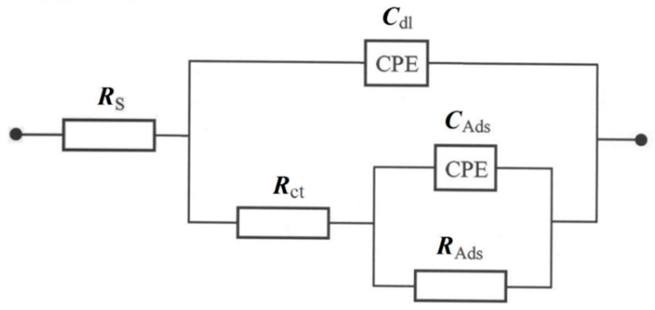
| η/mV | Rct/Ω g | Cdl/µF g−1 s φ1−1 | RAds/Ω g | CAds/µF g−1 s φ2−1 |
|---|---|---|---|---|
| Ni Foam | ||||
| 270 | 0.187 ± 0.033 | 120,933 ± 12,554 | 41.756 ± 4.524 | 144,293 ± 11,985 |
| 320 | 0.129 ± 0.025 | 127,147 ± 12,430 | 9.047 ± 0.206 | 103,520 ± 11,383 |
| 370 | 0.073 ± 0.008 | 114,453 ± 6488 | 1.844 ± 0.105 | 81,360 ± 5257 |
| 420 | 0.086 ± 0.008 | 89,627 ± 3612 | 0.616 ± 0.008 | 67,867 ± 2587 |
| 470 | 0.075 ± 0.007 | 81,493 ± 3352 | 0.289 ± 0.007 | 73,840 ± 3282 |
| 520 | 0.061 ± 0.005 | 67,600 ± 3119 | 0.176 ± 0.005 | 90,933 ± 3627 |
| 570 | 0.064 ± 0.005 | 76,773 ± 2646 | 0.114 ± 0.005 | 78,717 ± 5113 |
| 620 | 0.047 ± 0.002 | 8720 ± 414 | 0.123 ± 0.003 | 129,227 ± 9950 |
| Co-modified Ni foam | ||||
| 270 | 0.052 ± 0.006 | 541,047 ± 15,371 | 5.265 ± 0.417 | 670,980 ± 28,526 |
| 320 | 0.035 ± 0.004 | 224,899 ± 26,583 | 1.239 ± 0.009 | 690,541 ± 6229 |
| 370 | 0.030 ± 0.004 | 218,716 ± 10,076 | 0.217 ± 0.004 | 412,736 ± 7235 |
| 420 | 0.027 ± 0.003 | 188,682 ± 8730 | 0.214 ± 0.004 | 444,831 ± 6886 |
| 470 | 0.028 ± 0.003 | 141,993 ± 5113 | 0.128 ± 0.003 | 475,169 ± 10,406 |
| 520 | 0.024 ± 0.002 | 121,588 ± 3725 | 0.089 ± 0.002 | 488,446 ± 13,374 |
| 570 | 0.024 ± 0.002 | 161,622 ± 5287 | 0.052 ± 0.002 | 576,419 ± 31,772 |
| 620 | 0.022 ± 0.004 | 105,473 ± 9599 | 0.041 ± 0.005 | 557,230 ± 91,804 |
| Mo-modified Ni foam | ||||
| 270 | 0.081 ± 0.011 | 822,987 ± 85,015 | 2.274 ± 0.052 | 1,743,525 ± 143,562 |
| 320 | 0.069 ± 0.010 | 540,724 ± 66,936 | 0.667 ± 0.018 | 1,916,698 ± 61,430 |
| 370 | 0.066 ± 0.009 | 599,202 ± 157,063 | 0.296 ± 0.007 | 1,680,668 ± 168,453 |
| 420 | 0.068 ± 0.017 | 1,024,082 ± 152,342 | 0.181 ± 0.014 | 1,045,659 ± 157,476 |
| 470 | 0.052 ± 0.004 | 200,204 ± 20,927 | 0.150 ± 0.006 | 1,512,226 ± 94,060 |
| 520 | 0.035 ± 0.008 | 783,766 ± 74,144 | 0.111 ± 0.008 | 1,337,607 ± 118,659 |
| 570 | 0.030 ± 0.011 | 1,008,571 ± 140,070 | 0.091 ± 0.011 | 916,327 ± 126,682 |
| 620 | 0.023 ± 0.003 | 1,271,429 ± 181,585 | 0.087 ± 0.003 | 1,524,620 ± 324,842 |
| η/mV | Solution | Catalysts | Rct/Ω cm2 | j(η= 0.3V)/A cm−2 | Ref. |
|---|---|---|---|---|---|
| 270 | 0.1 M NaOH | Co-modified Ni foam | 31.9 | 9.2 × 10⁻⁵ | This work |
| 420 | 0.1 M NaOH | Co-modified Ni foam | 16.6 | - | This work |
| 430 | 0.1 M KOH | Co(OH)2/C | 8.5 | - | 35 |
| 420 | 0.1 M NaOH | Co oxide/Fe | 17.5 | 1.15 × 10⁻⁵ | 28 |
| 270 | 0.1 M NaOH | Mo-modified Ni foam | 27.1 | 1.6 × 10⁻⁴ | This work |
| 420 | 0.1 M NaOH | Mo-modified Ni foam | 22.6 | - | This work |
| 290 | 1.0 M KOH | NiMoO4 nanowire/Ni foam | 981 * | - | 36 |
| 210 | 30% KOH | Ni-Fe-C-Mo/Ni mesh | 364 * | - | 37 |
| 438 | 1.0 M NaOH | Pt | 80 | ~4 × 10⁻⁵ ** | 40 |
| 278 | 0.1 M KOH | RuO2/GC *** | 142 * | ~5 × 10⁻⁴ ** | 41 |
| 250 | 0.1 M KOH | Pd/FTO **** | 42 * | ~12 × 10−3 ** | 42 |
| Bath Constituents | Concentration (M) | Operating Parameters |
|---|---|---|
| Electrodeposition of Co | ||
| CoCl2 × 6 H2O (99%, Sigma Aldrich, Saint Louis, MO, USA) | 0.10 | Anode: Pt foil |
| NaCl (99.9%, POCH, Gliwice, Poland) | 0.02 | Cathode: Ni foam |
| Temperature: 303 K | ||
| Deposition time: 300 s | ||
| Current-density: 0.52 mA cm−2 | ||
| Solution pH: 4.5 | ||
| Electrodeposition of Mo | ||
| (NH4)6Mo7O24·4H2O (≥99.3%, Merck, Darmstadt, Germany) CH3CO2NH4 (≥98.0%, Merck, Darmstadt, Germany) CH3COOK (≥99.0%, Sigma Aldrich, Saint Louis, USA) | 1.95 × 10⁻⁴ 0.26 0.26 | Anode: Pt foil |
| Cathode: Ni foam | ||
| Temperature: 303 K | ||
| Deposition time: 1800 s | ||
| Current density: 5.2 mA cm−2 | ||
| Solution pH: 6.8 | ||
Publisher’s Note: MDPI stays neutral with regard to jurisdictional claims in published maps and institutional affiliations. |
© 2021 by the authors. Licensee MDPI, Basel, Switzerland. This article is an open access article distributed under the terms and conditions of the Creative Commons Attribution (CC BY) license (https://creativecommons.org/licenses/by/4.0/).
Share and Cite
Łuba, M.; Mikołajczyk, T.; Kuczyński, M.; Pierożyński, B.; Kowalski, I.M. Enhancing the Effectiveness of Oxygen Evolution Reaction by Electrodeposition of Transition Metal Nanoparticles on Nickel Foam Material. Catalysts 2021, 11, 468. https://0-doi-org.brum.beds.ac.uk/10.3390/catal11040468
Łuba M, Mikołajczyk T, Kuczyński M, Pierożyński B, Kowalski IM. Enhancing the Effectiveness of Oxygen Evolution Reaction by Electrodeposition of Transition Metal Nanoparticles on Nickel Foam Material. Catalysts. 2021; 11(4):468. https://0-doi-org.brum.beds.ac.uk/10.3390/catal11040468
Chicago/Turabian StyleŁuba, Mateusz, Tomasz Mikołajczyk, Mateusz Kuczyński, Bogusław Pierożyński, and Ireneusz M. Kowalski. 2021. "Enhancing the Effectiveness of Oxygen Evolution Reaction by Electrodeposition of Transition Metal Nanoparticles on Nickel Foam Material" Catalysts 11, no. 4: 468. https://0-doi-org.brum.beds.ac.uk/10.3390/catal11040468