Article

Microwave Breast Imaging Using Compressed Sensing Approach of Iteratively Corrected Delay Multiply and Sum Beamforming

by
Mohammad Tariqul Islam
1,*,
Md Tarikul Islam
1,
Md Samsuzzaman
2,
Salehin Kibria
1 and
Muhammad E. H. Chowdhury
3,*
1
Department of Electrical, Electronic and Systems Engineering, Universiti Kebangsaan Malaysia, Bangi, Selangor 43600, Malaysia
2
Department of Computer and Communication Engineering, Patuakhali Science and Technology University, Dumki, Patuakhali 8602, Bangladesh
3
Department of Electrical Engineering, Qatar University, Doha 2713, Qatar
*
Authors to whom correspondence should be addressed.
Submission received: 7 December 2020 / Revised: 19 January 2021 / Accepted: 26 January 2021 / Published: 8 March 2021
(This article belongs to the Special Issue Multimodality Breast Imaging 2021)

Abstract

:
Microwave imaging (MI) is a consistent health monitoring technique that can play a vital role in diagnosing anomalies in the breast. The reliability of biomedical imaging diagnosis is substantially dependent on the imaging algorithm. Widely used delay and sum (DAS)-based diagnosis algorithms suffer from some significant drawbacks. The delay multiply and sum (DMAS) is an improved method and has benefits over DAS in terms of greater contrast and better resolution. However, the main drawback of DMAS is its excessive computational complexity. This paper presents a compressed sensing (CS) approach of iteratively corrected DMAS (CS-ICDMAS) beamforming that reduces the channel calculation and computation time while maintaining image quality. The array setup for acquiring data comprised 16 Vivaldi antennas with a bandwidth of 2.70–11.20 GHz. The power of all the channels was calculated and low power channels were eliminated based on the compression factor. The algorithm involves data-independent techniques that eliminate multiple reflections. This can generate results similar to the uncompressed variants in a significantly lower time which is essential for real-time applications. This paper also investigates the experimental data that prove the enhanced performance of the algorithm.

1. Introduction

Microwave imaging (MI) has been verified to be a reliable health monitoring technique that can play a prime role in diagnosing anomalies in breast tissue. A microwave transceiver can recognize small signal variations with the changes in the electrical properties of human tissues. Recent advances in microwave imaging show that it can be a viable solution as preclinical detection tools in human body imaging [1,2,3,4]. The on-phantom experiments shown in [4] describe the functionality of a microwave sensor for the successful localization of the target. The iterative reconstruction is referred to as post-processing of the acquired data. The clinical realization of MI is discussed with recent advancements in [3], where the MI technology is selected as a complementary modality of the existing screening systems for breast cancer. The potential role of MI and the clinical advances of this imaging is discussed in [1,2] where MI is described as a rapid and inexpensive method of diagnosis as compared to others.
The reliability of biomedical imaging-based diagnosis is substantially dependent on the imaging algorithm. There are three categories of MI, active, passive and hybrid [5]. Beamforming is the primary part of image reconstruction of active radar-based MI [6,7]. Among the two types of beamformers, data-independent beamformers take less time in image reconstruction while the data-adaptive beamformers have excessive computational complexity but produce better images [8].
The differential microwave diagnosis for breast [9], DMAS image reconstruction algorithm [10] and DAS algorithm have been suggested to improve imaging performance like the robust, interference-canceling, balanced deblurring. Several data-independent algorithms were utilized for microwave-based image processing, like Tissue Sensing Adaptive Radar (TSAR) [11] and confocal microwave diagnosis algorithm [12,13]. However, DAS and its variations are much more popular owing to their robust performance and simplicity. Most of these algorithms are applied to the received signal for the reconstruction of breast interior, feature extraction and post-processing to locate abnormalities. Another data-independent beamformer is DMAS which provides improved contrast and resolution in the reconstructed images by trading the complexity of computation. Several variants of DAS were introduced besides DMAS, including coherence factor DAS [14], improved DAS [15], and the iterative variant of DAS [16]. The improvements of DMAS over DAS has been proven in [13,17]. The iterative variant of DAS and DMAS is proposed in [18] where the authors removed the background clutter in the reconstructed images. The reconstructed images of the DMAS algorithm were used to detect the tumor after normalizing the maximum scatterer [19]. The compressed sensing approach has been reported in several image reconstruction techniques in MI [20,21]. A Bayesian CS approach to MI of an inhomogeneous object based on mesh discretization and electric field integral equation in the imaging region was proposed [22]. The CS was applied to separable surrogate functionals (SSF) optimization to reduce the sampling data volume in [23]. None of them is applied to the most popular DAS or variants of DAS algorithms. An iterative three-dimensional non-linear inverse scattering technique was proposed for the reduction of computational time using a nondispersive material model [24].
In this paper, a compressed sensing iterative variant of the DMAS algorithm is introduced for increasing the performance and reducing the runtime for microwave imaging applications using iteratively corrected DMAS beamforming. The proposed CS-ICDMAS works on the basis of computing all the channel power and eliminating comparatively lower power channels. This reduces the number of observations and saves the calculation time without decreasing the image quality. The practical imaging was tested, and the numerical analysis is also presented.

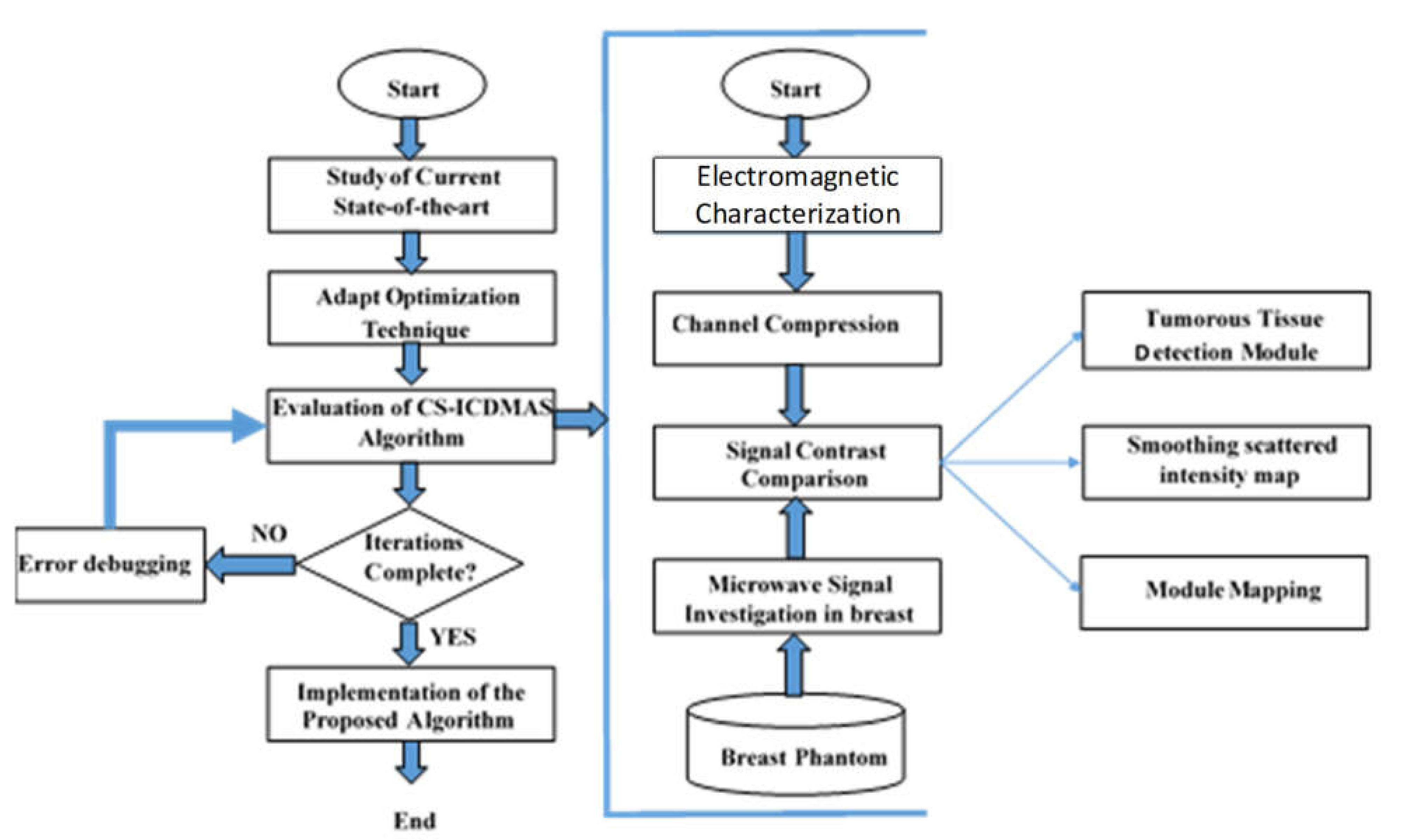
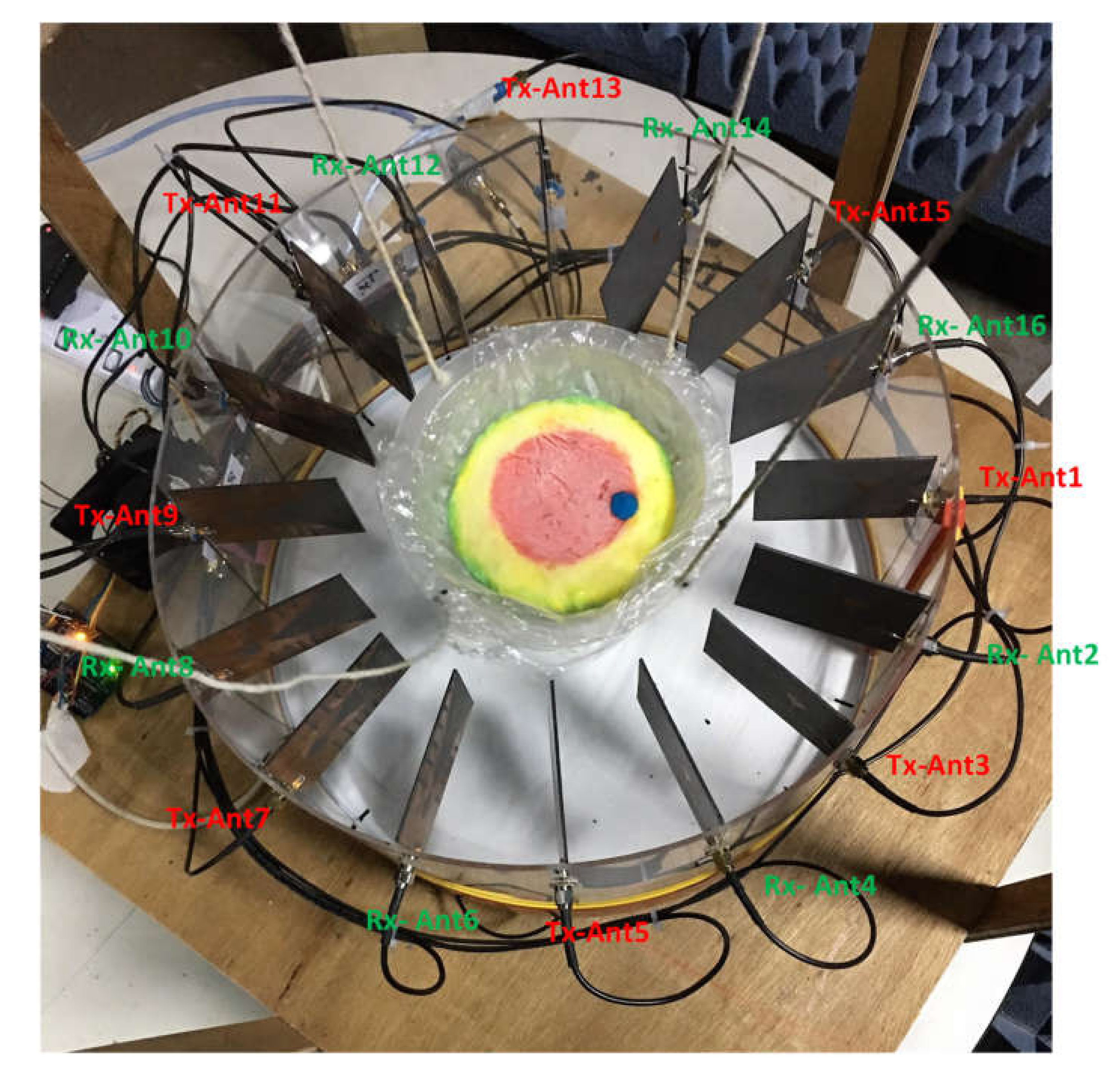
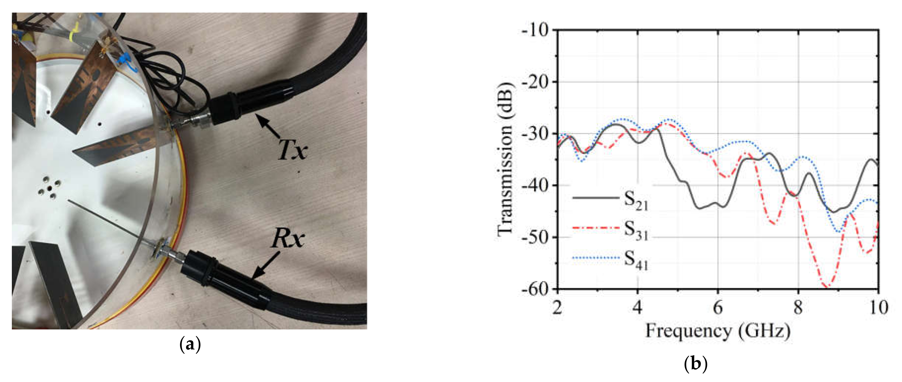
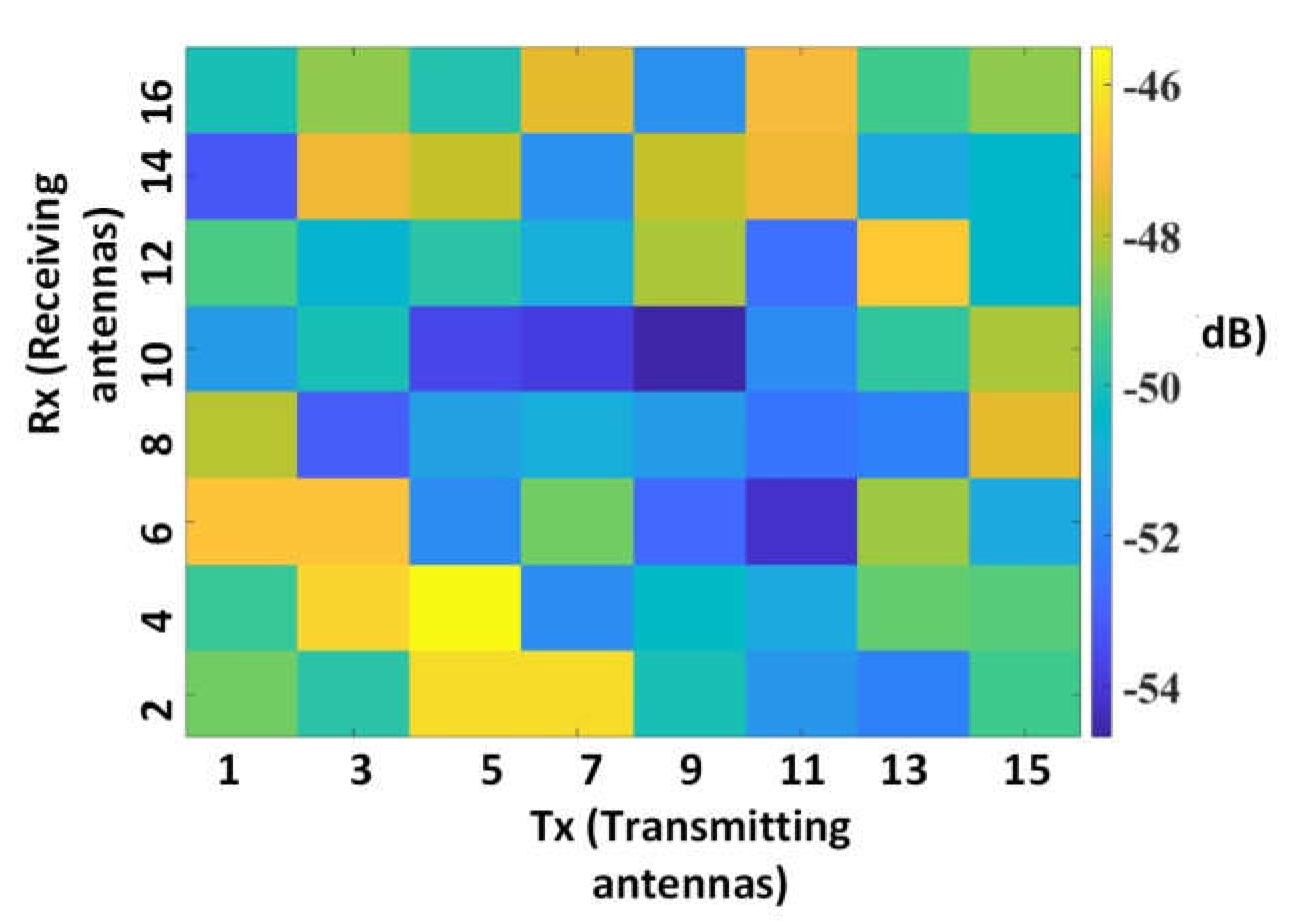
2. Imaging System Setup

The detailed flowchart of the research methodology is presented in Figure 1. The imaging system consisted of a total of 16 antenna arrays with a mechanical rotating platform. A set of heterogeneous phantoms was tested. The system setup and phantom fabrication procedures can be found in the literature [15]. The system comprised eight transmitters and eight receiver antennas. A rotating turntable held the antenna array and data were taken using a MATLAB-based image processing platform using a vector network analyzer (VNA). The turntable rotated 360 degrees at a step of 7.2 degrees that resulted in 50 equal datapoints. As a result, the total number of channels was 8 × 8 × 50. Figure 2 shows the imaging system setup while collecting data from the system in the presence of a breast phantom.

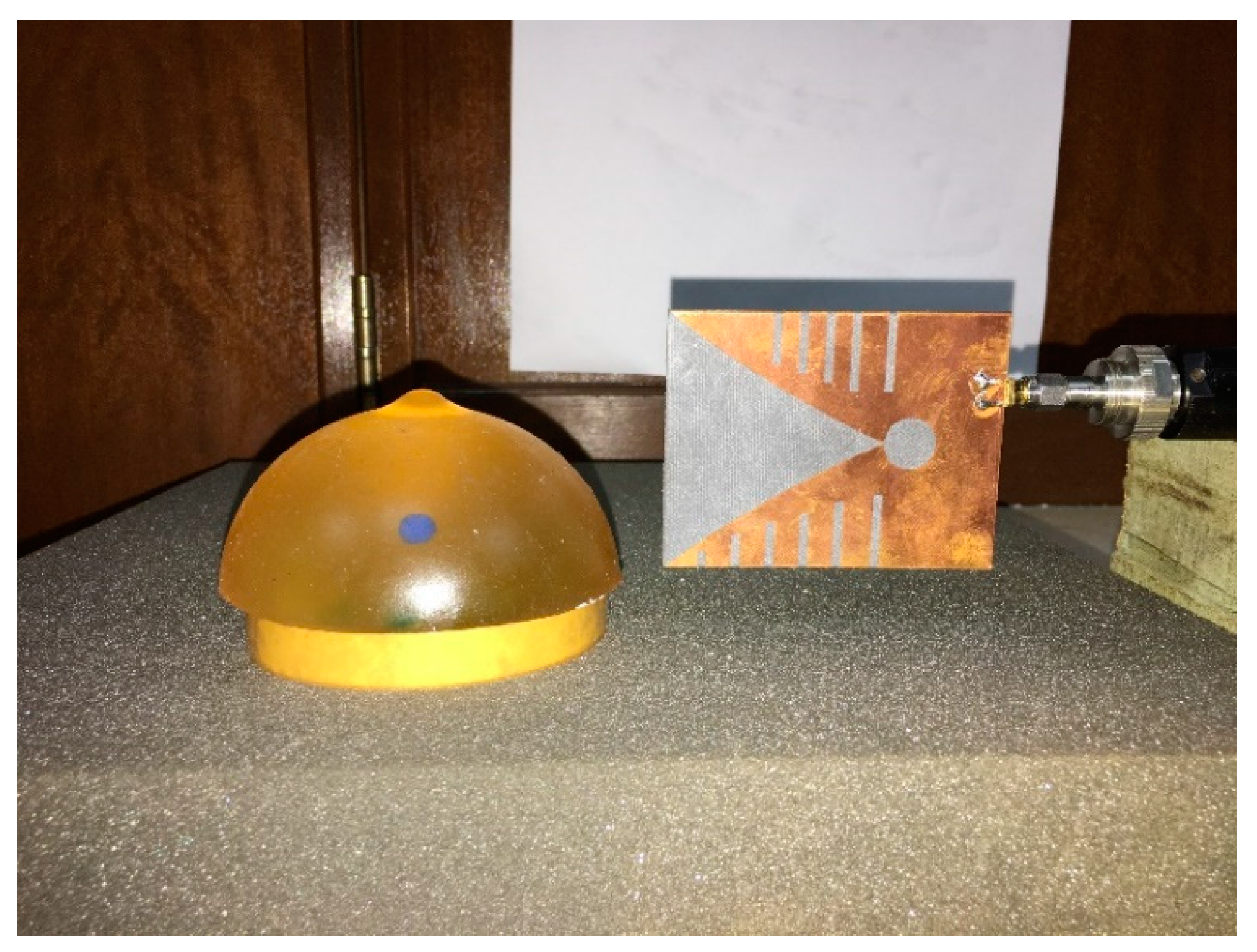
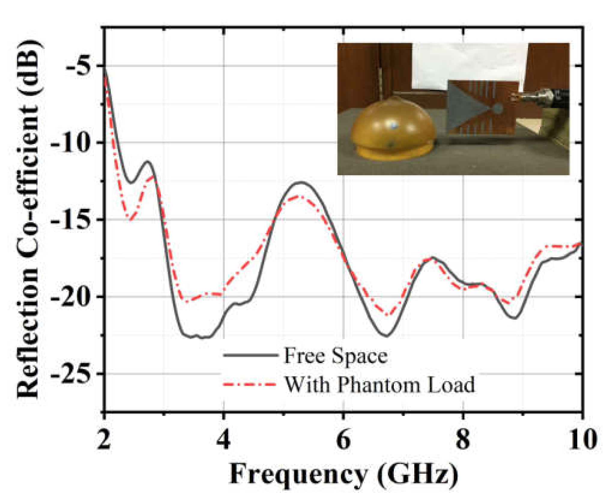
Antenna Performance Analysis

The antenna used in the proposed system is a modified Vivaldi antenna. The design evaluation of the antenna can be found in [17]. The antenna has dimensions of 77.72 mm × 60 mm and a bandwidth from 2.70–11.20 GHz. The reflection coefficient is considered in free space and the heavy load of the phantom in this work. The setup for taking measurements in the presence of a phantom is shown in Figure 3. Figure 4 illustrates the measured reflection coefficient in free space and a phantom load. It was observed that the antenna could firmly maintain its bandwidth in both scenarios with minimal distortions. The mutual coupling between the adjacent antennas was also investigated. Figure 5a shows the setup of Tx and Rx antennas considered for measuring the isolation between the adjacent antennas. The results are presented in Figure 5b It was observed that the antennas had sound isolation and were maintained between −26 dB and −60 dB.

3. Beamforming Method

The proposed algorithm was analyzed based on the microwave signal contrast. The scattered microwave signals from healthy and unhealthy breast phantoms were compared. First, microwave signal contrast comparison took place between the reference microwave signal using numerical simulation of the full-wave time domain model and the scattered signal from the computational phantom. The successive approximation method was obtained to get the exact position and size of the tumor. There was no coupling medium between the phantom and the antenna; as a result, we needed to eliminate skin reflections. Thus, for artifact removal, the rotation subtraction was applied, which relied on the comparison between the original scattering and at least a single-rotated scattering [15]. The array of antennas is placed around the Region of Interest (ROI) in such systems. The array was rotated once, and the offset data were collected and recorded as a reference of initial radiance.

3.1. Channel Compression on Skin Reflection Removal

Different methods of artifact removal including rotation subtraction [25] and singular value decomposition (SVD) were proposed [26]. In the rotation subtraction method, it was assumed that the tumor was out of the axis of the rotation and the response received from the tumor would be well-preserved even after the subtraction of the scattered rotated position signals. In the SVD method, the breast shape is restricted as uniform and submerged in a coupling medium and the antenna array is maintained at a certain distance from the skin. In this work, the artifact removal was performed using the rotation subtraction method. The antenna array completed full rotation surrounding the phantom at a 7.2˚ step with a total of 8 × 8 × 50 channels. The equally sliced datapoint was denoted = 50. The system collected complex S-parameters in the frequency domain, S (f, tx, rx, φ), where f is the frequency, tx = 1, 3, 5, 7, 9, 11, 13, 15 and rx = 2, 4, 6, 8, 10, 12, 14, 16 are the transmitting and receiving antennas, respectively, and the alignment of the rotating platform angle is φ. A total of 201 datapoints was recorded for each rotation within the band from 2.7 to 8.0 GHz. Once the data were recorded for the original illumination, the array s rotated around the phantom to get offset data. The difference of the data from the different illuminations was computed to remove the effect of the skin.
In this work, the sample S (f, tx, rx, φ) was parted into two matrices based on φ becoming odd and even, or Sodd(f,tx,rxodd), and Seven(f,tx,rxeven), individually, where φodd = odd number of datapoints (1, 3, 5,…Nφ-1) and φeven = even number of data points (2, 4,6,…Nφ). Thus, Sodd can be considered initial illumination and Seven—“offset” illumination. Finally, rotation subtraction was implemented by simply calculating the difference between the two matrices according to Equation (1):
S s k i n _ r e m o v e d ( f , t x , r x , φ o d d ) = S o d d ( f , t x , r x , φ o d d ) S e v e n ( f , t x , r x , φ e v e n )
The power of all the channels was calculated. The low-power channels were subtracted based on the compression factor ϗ. The measured 8 × 8 scattering matrix in the presence of a breast phantom is illustrated in Figure 6. The difference between the high- and low-power channels was visible. Afterwards, the total skin reflection data (Rskin_removed) were calculated based on Equation (2):
R s k i n _ r e m o v e d ( t x , r x , φ o d d ) = f S s k i n _ r e m o v e d ( f , t x , r x , φ o d d )
ϗ × n (Rskin_removed) channels with the highest power were considered for the imaging from Sskin_removed to produce compressed data as Scompressed(f,tx,rx, φodd), where n(Rskin_removed) is the number of channels and ϗ is the compression factor of 0 ≤ ϗ ≤ 1. The lower power channels were eliminated to reduce the execution time and make the process faster. After adjusting the skin reflections, the signals were converted to the time domain using the inverse Fourier transform to create Γ(t, tx, rx, φodd). Then, the data in the Γ(t, tx, rx, φodd) were processed via the delay multiply and sum (DMAS) algorithm for the reconstruction of the image [27,28]. Normally, DAS-based methods struggle in noisy settings where multiple reflections from various scattering sources need to be considered. In that case, DMAS outperforms DAS by generating sharper contrast images by utilizing the correlation process [29]. However, an earlier study reported that DMAS struggles in high-noise settings as well as in multiple target situations [30]. Therefore, in this research work, after applying compressed sensing (CS), we revised the typical DMAS algorithm by implementing iterative correction of the delay calculation. The correction was done by several iteration processes until convergence to the desired level of accuracy.

3.2. Compressed Sensing in DMAS

Three-dimensional Cartesian coordinates of all points inside the region of interest were represented in the i by 3 matrices, C, where i = 1,2,…, and I is the total number of points. Then, the I was generated from C by the I matrix, PC-C, containing the Euclidian distances between each possible pair of points in the imaging domain. Matrices ATx and ARx contained the optimized three-dimensional Cartesian coordinates of the transmitting and receiving antennas, respectively. Since the imaging domain was stationary, the antennas changed their distance from the points to be reconstructed as they rotated. Thus, ATxφodd and ARxφodd were generated by determining all the antenna positions considered in the original orientation. Then, PTxφodd-C and PC-Rxφodd, containing the distances from each point to the transmitting and receiving antennas, were calculated from C, ATxφodd, and ARxφodd. Finally, the delays needed for focusing each channel to focus on point i in C were evaluated by summing the distances of the transmitting and receiving antenna positions concerned to the point being focused. The wave propagation velocity in the background medium, air in this study (theoretically, speed of light c), was divided by the total distance to yield the appropriate delay, τ (i, rx, φodd), as indicated in Equation (3):
τ ( i , t x , r x , φ o d d ) = ε b ( P T x φ o d d C ( i , t x , l ) + P C R x φ o d d ( i , r x , l ) ) c
where εb is the dielectric constant of the coupling medium. The delay τ was calculated from the estimated shortest distance and the reflected signal from C(i), which are the straight-line Euclidean distances calculated previously. The delays were further added to the signals for delivering a proper delayed signal. After multiplying by the paired delayed signal, they were summed for determining the scatter intensity at the allotted point in the ROI as shown in Equation (4). The paired signal multiplication compensated coherent signals together with higher values and hence improved the performance of DMAS over DAS [15,27].
ϒ D M A S ( i ) = φ o d d = 1 N / 2 t x = 1 T x r x = 1 R x φ o d d = φ o d d N / 2 t x = t x T x r x = r x + 1 R x Γ ( t τ ( i , t x , r x , φ o d d ) Δ t , t x , r x , φ o d d ) × Γ ( t τ ( i , t x , r x , φ o d d ) Δ t , t x , r x , φ o d d ) d t

3.3. Iterative Correction of CS-DMAS
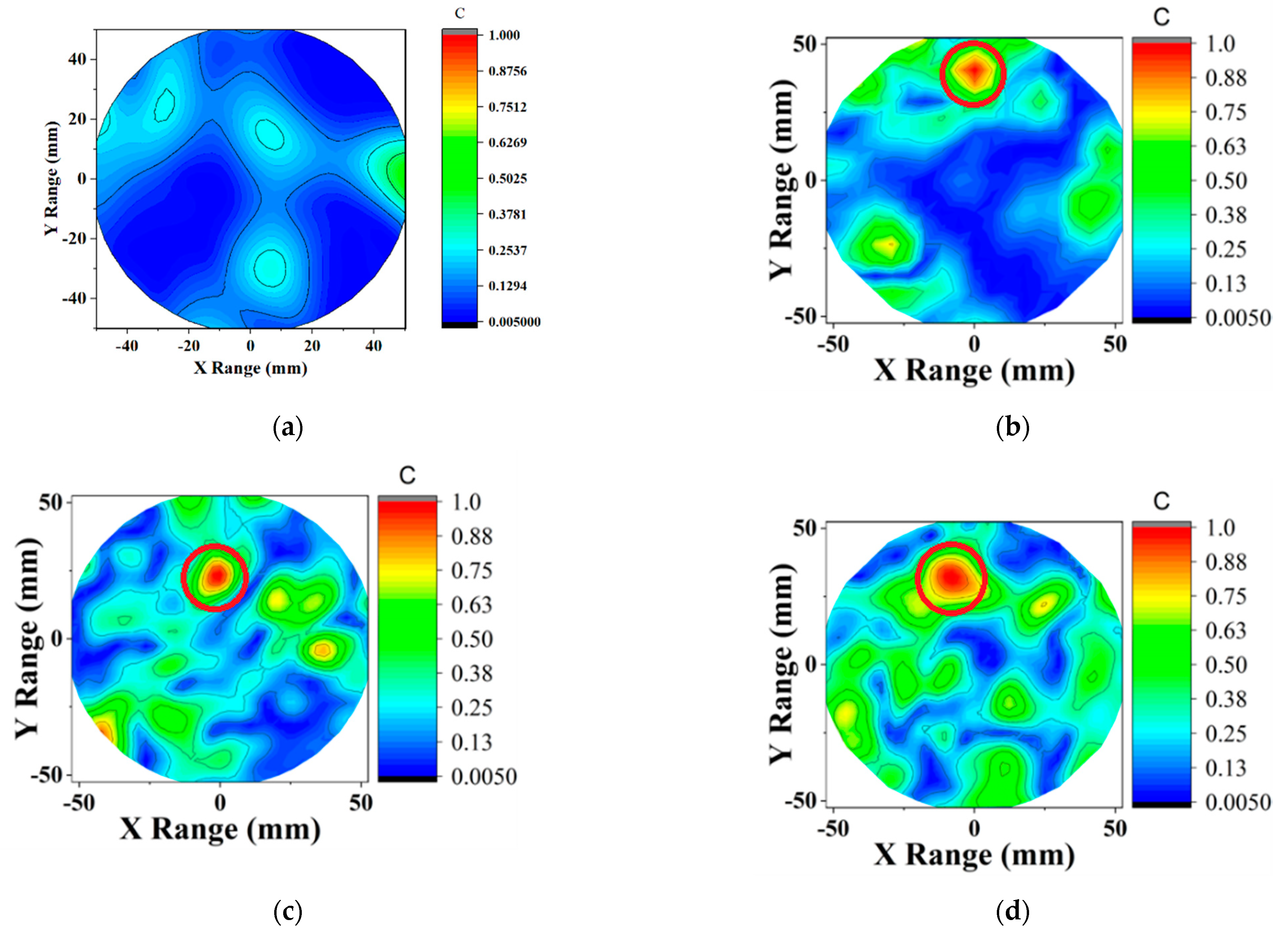
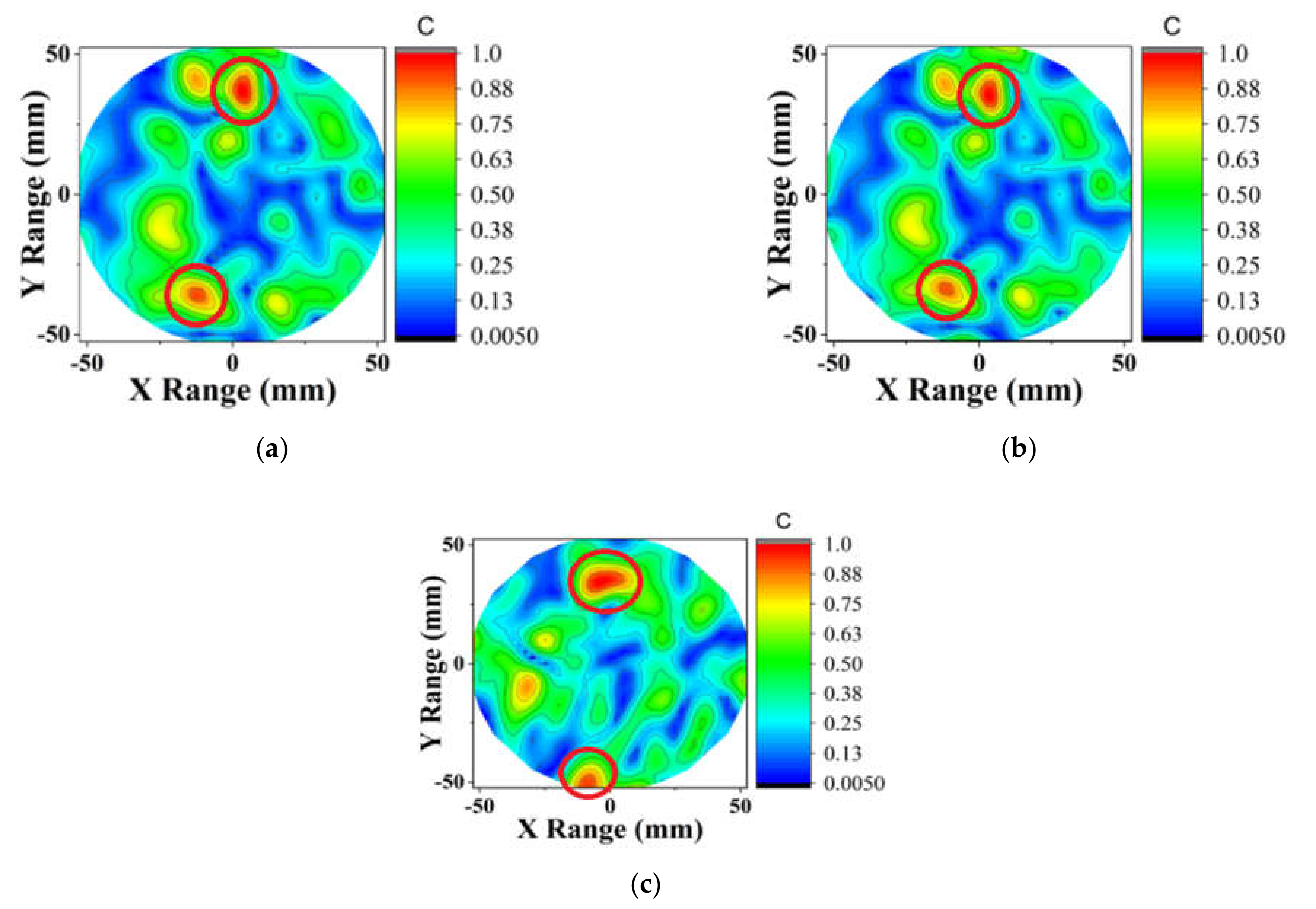
The dielectric materials diminish the propagation speed; this results in increased time delay. Thus, the higher value of ϒ in the C region can be implied as to the higher dielectric region. The additional time adjustment can be made by properly increasing the distance while calculating τ. Here, we introduce an iterative approach to estimate the best-fitted delay as well as the scattered intensity map (SIM) evaluation. At the same time, a greater estimation of SIM is dependent on the proper adjustment of τ. However, the iterative process can lead to vulnerability and noise-sensitivity if we use ϒ directly. An inverse distance weighted integral averaging was introduced to produce a smoothed SIM, ϒ’(i). This method can be considered analogous to applying the 3D Green’s function in the distorted Born iterative method.
ϒ ( i ) = C ϒ D M A S n 1 ( i ) 1 + P C C ( i , j ) d j
An extra time, PC-C(i,j), was adjusted by appropriately increasing the distances.
Then, the following equation was used to calculate modified delay:
τ ( i , t x , r x , φ o d d ) = τ ( i , t x , r x , φ o d d ) + ϒ ( i ) c
Here, c is the speed of light.
ϒ D M A S ( i ) = φ o d d = 1 N / 2 t x = 1 T x r x = 1 R x φ o d d = φ o d d N / 2 t x = t x T x r x = r x + 1 R x Γ ( t τ ( i , t x , r x , φ o d d ) Δ t , t x , r x , φ o d d ) × Γ ( t τ ( i , t x , r x , φ o d d ) Δ t , t x , r x , φ o d d ) d t
The new set of delays was used to reconstruct the SIM. Finally, the completion benchmark was inspected for convergence. The iteration of Equations (7) and (8) was evaluated for n = 1, 2,…, 7.
E ϒ = i ϒ D M A S n ϒ D M A S n 1
The iteration was terminated when Eϒ decreased the expected level of accuracy after achieving convergence. In this paper, Eϒ was < 10−5.

4. Imaging Results

The simulation of DMAS was performed on an HP Workstation Mid 2018 with a 3.7 GHz Intel Xeon E3-1245 processor and 32 GB 2400 MHz DDR4 RAM.

4.1. Contour Images

Two sets of the lab-made heterogeneous phantom were used to evaluate the performance of the proposed beamformer. The first one had a single tumor inside (phantom 1) and another one was designed with two tumors (phantom 2). The heterogeneous phantoms 1 and 2 had four layers of skin, fat, gland and tumor to be as realistic as possible [31]. The relative permittivity and conductivity of the skin layer were 24 and 2.49 S/m. The permittivity and conductivity of the fat layer were 6 and 1.72 S/m. The gland layer had the permittivity and conductivity of 16 and 3.27 S/m. Last of all, the tumor layer had relative permittivity and conductivity of 64 and 4.98 S/m. All the data were presented at 4 GHz. The backscattered signals were collected using an array of 16 Vivaldi antennas surrounding the phantom using the Agilent N5227 VNA. A total of 3200 (8 × 8 × 50) observations were taken from 2.5 to 8 GHz. The computation was done for DMAS and CS-DMAS with several compression factors.
The reconstructed contour plot images are presented in Figure 7 and Figure 8 for phantom 1 and phantom 2, respectively. For the phantom 1 screening, DMAS successfully detected the tumor. After applying the compression to half of the observations ϗ (1600) and applying the Born iterative method, DMAS was still able to detect the target. The iteration converged after seven trials resulting in little delay variations. Thus, the location of the tumor was inconsistent, but the results are still promising as a screening tool. Figure 7c and Figure 8c show the image of CS-ICDMAS after compressing the observations of one-fourth of the total channel ϗ (800). It still identified the tumor in a red circle with some noise saving execution time and computational complexity.

4.2. Numerical Imaging Data

The numerical assessments in terms of signal-to-mean ratio (SMR) and execution time is described in this section. The SMR states the proportion of the maximum tumor energy to the mean energy from backscattered signals at a similar sample [32].
S M R = M a x i m u m _ T u m o r _ E n e r g y M e a n _ E n e r g y
Numerical imaging data in terms of SMR and execution time are shown in Table 1. The graphical representation of the signal to mean ratio and execution time against the compression factor is presented in Figure 9a,b. The SMR of CS-ICDMAS remains decreased with the compression factor. The SMR shows a proportional relation with the execution time. But the drop of SMR concerning execution time is not huge. The proposed algorithm shows exponential improvement in reducing execution time by maintaining image quality and detection. These results validate the capability of CS-ICDMAS to decrease computation time and reduce computational complexity by eliminating the weak channels by preserving detection performance. A comparison of the execution time for the DAS, CF (Coherence Factor)-DAS, DMAS and ICDMAS with the proposed method is provided in Table 2. It is noted that the proposed algorithm can reduce the time required for computations and simultaneously gives similar imaging output.

5. Conclusions

This work introduces a new compressed sensing approach of iteratively corrected delay multiply and sum beamforming over the well-known DMAS in terms of microwave imaging of the breast. The main disadvantage of conventional DMAS is the high computation load and runtime. An array of 16 antennas was used to receive the backscattered microwave signal from a breast phantom. The compressed sensing approach was proposed by finding low-power channels across all the observations and eliminating them based on the compression factor. Then, an iterative approach was applied till convergence. The artifact removal was performed using the rotation subtraction method. Imaging data from the experimental system were tested with the proposed approach and the reconstructed image and numerical analysis were presented. The proposed CS-ICDMAS algorithm shows exponential improvement in reducing execution time as compared to DAS, CF-DAS, DMAS and ICDMAS by maintaining image quality and detection which validate the capability of CS-ICDMAS to decrease computation time and reduce computational complexity by eliminating the weak channels and preserving detection performance.

Author Contributions

M.T.I. (Md Tarikul Islam) and S.K. (Salehin Kibria) made substantial contributions to this research work regarding conception, design, analysis and writing of the manuscript. M.T.I. (Mohammad Tariqul Islam) and M.S. (Md. Samsuzzaman) analyzed the acquired data and the results, revised the manuscript, participated in measurements and provided intellectual suggestions. M.T.I. supervised the entire project and acquired the portion of the funding. M.E.H.C. (Muhammad E. H. Chowdhury) revised the manuscript judgmentally for important intellectual content and provided precious advice and acquired funding. All authors have read and agreed to the published version of the manuscript.

Funding

This work was supported by the Ministry of Higher Education of Malaysia (MOHE), grant code No. FRGS/1/2018/TK04/UKM/01/3. This work was supported by Grant NPRP12S-0227-190164 from the Qatar National Research Fund, a member of Qatar Foundation, Doha, Qatar and the claims made herein are solely the responsibility of the authors. Open Access funding provided by the Qatar National Library.

Institutional Review Board Statement

Not applicable.

Acknowledgments

This work was supported by Grant NPRP12S-0227-190164 from the Qatar National Research Fund, a member of Qatar Foundation, Doha, Qatar and the internal grant of Qatar University QUST-1-CENG-2021-6 and the claims made herein are solely the responsibility of the authors.

Conflicts of Interest

The authors declare no conflict of interest.

Abbreviations List

CSCompressed sensing
CFCoherence Factor
CS-ICDMASCompressed sensing using iteratively corrected DMAS
DASDelay and sum
DMASDelay multiply and sum
MIMicrowave imaging
ROIRegion of interest
SIMScattered intensity map
SMRSignal-to-mean ratio
SSFSeparable surrogate functionals
SVDSingular value decomposition
TSARTissue Sensing Adaptive Radar
VNAVector network analyzer

References

  1. Moloney, B.M.; O’Loughlin, D.; Abd Elwahab, S.; Kerin, M. Breast cancer detection—A synopsis of conventional modalities and the potential role of microwave imaging. Diagnostics 2020, 10, 103. [Google Scholar] [CrossRef] [PubMed] [Green Version]
  2. O’Loughlin, D.; O’Halloran, M.; Moloney, B.M.; Glavin, M.; Jones, E.; Elahi, M.A. Microwave breast imaging: Clinical advances and remaining challenges. IEEE Trans. Biomed. Eng. 2018, 65, 2580–2590. [Google Scholar] [CrossRef]
  3. Modiri, A.; Goudreau, S.; Rahimi, A.; Kiasaleh, K. Review of breast screening: Toward clinical realization of microwave imaging. Med. Phys. 2017, 44, e446–e458. [Google Scholar] [CrossRef]
  4. Bolomey, J.-C. Crossed viewpoints on microwave-based imaging for medical diagnosis: From genesis to earliest clinical outcomes. In The World of Applied Electromagnetics; Springer: Berlin/Heidelberg, Germany, 2018; pp. 369–414. [Google Scholar]
  5. Fear, E.C.; Li, X.; Hagness, S.C.; Stuchly, M.A. Confocal microwave imaging for breast cancer detection: Localization of tumors in three dimensions. IEEE Trans. Biomed. Eng. 2002, 49, 812–822. [Google Scholar] [CrossRef] [Green Version]
  6. Song, H.; Sasada, S.; Masumoto, N.; Kadoya, T.; Shiroma, N.; Orita, M.; Arihiro, K.; Okada, M.; Kikkawa, T. Detectability of breast tumors in excised breast tissues of total mastectomy by ir-uwb-radar-based breast cancer detector. IEEE Trans. Biomed. Eng. 2018, 66, 2296–2305. [Google Scholar] [CrossRef] [PubMed]
  7. Shao, W.; Edalati, A.; McCollough, T.R.; McCollough, W.J. A time-domain measurement system for uwb microwave imaging. IEEE Trans. Microw. Theory Tech. 2018, 66, 2265–2275. [Google Scholar] [CrossRef]
  8. Byrne, D.; Craddock, I.J. Time-domain wideband adaptive beamforming for radar breast imaging. IEEE Trans. Antennas Propag. 2015, 63, 1725–1735. [Google Scholar] [CrossRef]
  9. Abbosh, A.; Mohammed, B.; Bialkowski, K. Differential microwave imaging of the breast pair. IEEE Antennas Wirel. Propag. Lett. 2016, 15, 1434–1437. [Google Scholar] [CrossRef]
  10. Mozaffarzadeh, M.; Sadeghi, M.; Mahloojifar, A.; Orooji, M. Double-stage delay multiply and sum beamforming algorithm applied to ultrasound medical imaging. Ultrasound Med. Biol. 2018, 44, 677–686. [Google Scholar] [CrossRef] [PubMed] [Green Version]
  11. Lavoie, B.R.; Okoniewski, M.; Fear, E.C. Optimizing microwave-radar imaging parameters. In Proceedings of the IEEE 2016 17th International Symposium on Antenna Technology and Applied Electromagnetics (ANTEM), Montreal, QC, Canada, 10–13 July 2016; pp. 1–2. [Google Scholar]
  12. Elahi, M. Confocal Microwave Imaging and Artifact Removal Algorithms for the Early Detection of Breast Cancer. Ph.D. Thesis, NUI, Galway, Ireland, 2018. [Google Scholar]
  13. KaramFard, S.S.; Asl, B.M. Fast delay-multiply-and-sum beamformer: Application to confocal microwave imaging. IEEE Antennas Wirel. Propag. Lett. 2019, 19, 14–18. [Google Scholar] [CrossRef]
  14. Kibria, S.; Samsuzzaman, M.; Islam, M.T.; Mahmud, M.Z.; Misran, N.; Islam, M.T. Breast phantom imaging using iteratively corrected coherence factor delay and sum. IEEE Access 2019, 7, 40822–40832. [Google Scholar] [CrossRef]
  15. Klemm, M.; Craddock, I.; Leendertz, J.; Preece, A.; Benjamin, R. Improved delay-and-sum beamforming algorithm for breast cancer detection. Int. J. Antennas Propag. 2008, 2008. [Google Scholar] [CrossRef] [Green Version]
  16. Islam, M.T.; Mahmud, M.Z.; Islam, M.T.; Kibria, S.; Samsuzzaman, M. A Low Cost and Portable Microwave Imaging System for Breast Tumor Detection Using UWB Directional Antenna Array. Sci. Rep. 2019, 9, 15491. [Google Scholar] [CrossRef] [PubMed] [Green Version]
  17. Islam, M.T.; Samsuzzaman, M.; Kibria, S.; Misran, N.; Islam, M.T. Metasurface Loaded High Gain Antenna Based Microwave Imaging Using Iteratively Corrected Delay Multiply and Sum Algorithm. Sci. Rep. 2019, 9, 17317. [Google Scholar] [CrossRef] [PubMed] [Green Version]
  18. Reimer, T.; Solis-Nepote, M.; Pistorius, S. The application of an iterative structure to the delay-and-sum and the delay-multiply-and-sum beamformers in breast microwave imaging. Diagnostics 2020, 10, 411. [Google Scholar] [CrossRef]
  19. Kranold, L.; Taherzadeh, M.; Nabki, F.; Coates, M.; Popovic, M. Microwave breast screening prototype: System miniaturization with ic pulse radio. IEEE J. Electromagn. Rf Microw. Med. Biol. 2020. [Google Scholar] [CrossRef]
  20. Zhou, T.; Zhu, A.; Shen, Y.; Li, H.; Li, C.; Hangfu, J. Single frequency microwave imaging based on compressed sensing. In Proceedings of the 2018 IEEE Radio and Wireless Symposium (RWS), Anaheim, CA, USA, 15–18 January 2018; pp. 133–135. [Google Scholar]
  21. Qin, Q.; Yu, S.Q.; Zhang, Q.H.; Shi, L.P.; Yi, C.; Zhang, S.H.; Liu, G.X. Microwave imaging based on compressive sensing method. In Proceedings of the 2019 IEEE International Conference on Computational Electromagnetics (ICCEM), Shanghai, China, 20–22 March 2019; pp. 1–3. [Google Scholar]
  22. Yu, S.Q.; Zhang, Q.H.; Qin, Q.; Shi, L.P.; Yi, C.; Zhang, S.H.; Liu, G.X. Microwave imaging of inhomogeneous objects based on bayesian compressed sensing. In Proceedings of the 2019 International Applied Computational Electromagnetics Society Symposium-China (ACES), Miami, FL, USA, 14–18 April 2019; pp. 1–2. [Google Scholar]
  23. Fang, Y.; Wang, B.; Sun, C. Three-dimensional near-field microwave imaging approach based on compressed sensing. In Proceedings of the 2015 International Symposium on Antennas and Propagation (ISAP), Tasmania, Australia, 9–12 November 2015; pp. 1–4. [Google Scholar]
  24. Gibbins, D.; Byrne, D.; Henriksson, T.; Monsalve, B.; Craddock, I.J. Less becomes more for microwave imaging: Design and validation of an ultrawide-band measurement array. IEEE Antennas Propag. Mag. 2017, 59, 72–85. [Google Scholar] [CrossRef]
  25. O’Loughlin, D.; Benchakroun, H.; Lowery, A. Rotational artefact removal for radar-based breast imaging: Effects on image quality. In Proceedings of the 2020 XXXIIIrd General Assembly and Scientific Symposium of the International Union of Radio Science, Rome, Italy, 29 August–5 September 2020; IEEE: Rome, Italy, 2020; pp. 1–4. [Google Scholar]
  26. Felício, J.M.; Bioucas-Dias, J.M.; Costa, J.R.; Fernandes, C.A. Microwave breast imaging using a dry setup. IEEE Trans. Comput. Imaging 2019, 6, 167–180. [Google Scholar] [CrossRef]
  27. Lim, H.B.; Nhung, N.T.T.; Li, E.-P.; Thang, N.D. Confocal microwave imaging for breast cancer detection: Delay-multiply-and-sum image reconstruction algorithm. IEEE Trans. Biomed. Eng. 2008, 55, 1697–1704. [Google Scholar] [PubMed]
  28. Bahramiabarghouei, H.; Porter, E.; Santorelli, A.; Gosselin, B.; Popović, M.; Rusch, L.A. Flexible 16 antenna array for microwave breast cancer detection. IEEE Trans. Biomed. Eng. 2015, 62, 2516–2525. [Google Scholar] [CrossRef]
  29. Mozaffarzadeh, M.; Mahloojifar, A.; Orooji, M.; Adabi, S.; Nasiriavanaki, M. Double-stage delay multiply and sum beamforming algorithm: Application to linear-array photoacoustic imaging. IEEE Trans. Biomed. Eng. 2018, 65, 31–42. [Google Scholar] [CrossRef] [PubMed] [Green Version]
  30. Park, S.; Karpiouk, A.B.; Aglyamov, S.R.; Emelianov, S.Y. Adaptive beamforming for photoacoustic imaging. Opt. Lett. 2008, 33, 1291–1293. [Google Scholar] [CrossRef] [PubMed]
  31. Islam, M.T.; Samsuzzaman, M.; Kibria, S.; Islam, M.T. Experimental breast phantoms for estimation of breast tumor using microwave imaging systems. IEEE Access 2018, 6, 78587–78597. [Google Scholar] [CrossRef]
  32. Al-Zuhairi, D.T.; Abed, A.M.; Gahl, J.M.; Islam, N.E. Phase-based window function and cd-dmas beamforming for microwave breast cancer detection. IET Microw. Antennas Propag. 2020, 14, 608–616. [Google Scholar] [CrossRef]
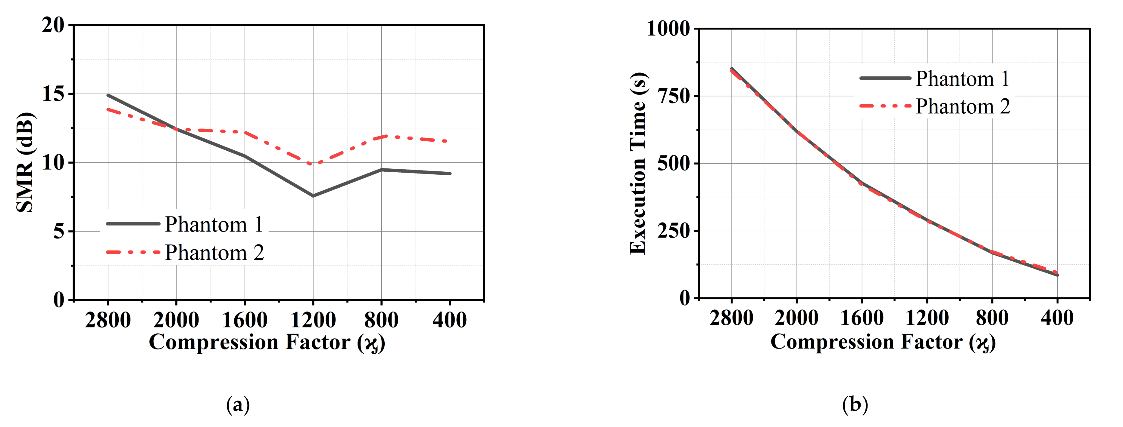
Figure 1. Flowchart of the research methodology.
Diagnostics 11 00470 g001
Figure 2. Imaging system setup (data-taking mode).
Diagnostics 11 00470 g002
Figure 3. Reflection coefficient measurement with a phantom load.
Diagnostics 11 00470 g003
Figure 4. Measured reflection coefficient in free space and a phantom load.
Diagnostics 11 00470 g004
Figure 5. (a) Mutual coupling measurements set up with adjacent antennas (b) Transmission results.
Diagnostics 11 00470 g005
Figure 6. The 8 × 8 scattering matrix measured in the presence of a breast phantom.
Diagnostics 11 00470 g006
Figure 7. Contour plot of the reconstructed image of a single tumor phantom (a) without tumor, using (b) DMAS (left), (c) proposed CS-ICDMAS (50% compression) and (d) CS-ICDMAS with 75% compression.
Diagnostics 11 00470 g007
Figure 8. Contour plot of the reconstructed image of two tumor phantoms using (a) DMAS, (b) proposed CS-ICDMAS (50% compression), (c) CS-ICDMAS with 75% compression.
Diagnostics 11 00470 g008
Figure 9. (a) SMR and (b) execution time with respect to the compression factor.
Diagnostics 11 00470 g009
Table 1. Signal-to-mean ratio and execution time against the compression factor.
ϗSMR (dB)Execution Time (s)
Phantom 1Phantom 2Phantom 1Phantom 2
320015.2014.8714551440
280014.9013.86852843
200012.4312.42619620
160010.4712.21427421
12007.589.80290287
8009.4811.95169172
4009.2011.538695
Table 2. Comparison of the execution time with the methods presented in the literature.
MethodExecution Time(s)
DAS2087
CF-DAS2175
DMAS2425
ICDMAS1455
CS-ICDMAS (50% compression)427
CS-ICDMAS (75% compression)169
Publisher’s Note: MDPI stays neutral with regard to jurisdictional claims in published maps and institutional affiliations.

