
On-line Detection and Classification of PMSM Stator Winding Faults Based on Stator Current Symmetrical Components Analysis and the KNN Algorithm


Abstract
:1. Introduction
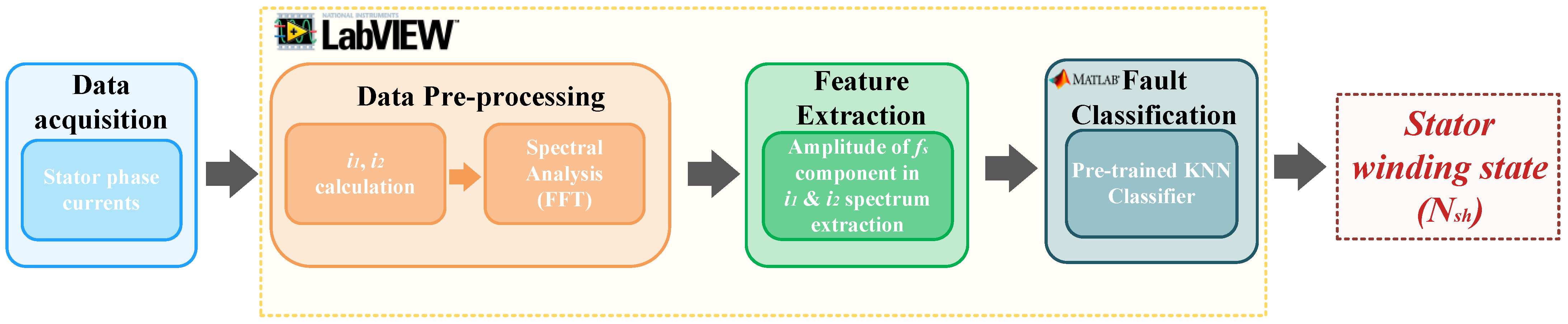
- A combination of symmetrical current component analysis and a simple machine learning algorithm for detecting inter-turn short circuits in PMSM stator windings, along with a proposition of an on-line diagnostic system based on LabVIEW and MATLAB environments;
- Proposing a stator winding fault classifier (KNN), the learning time of which is much shorter than in the case of artificial neural network based classifiers, widely described in the literature;
- A detailed examination of the impact of key parameter (hyper-parameters) changes of the tested classifier on its effectiveness and a proposal of the best solution,
- The proposal of a solution that allows the detection of failure at a very early stage, with one shorted turn in a stator winding and under various motor operating conditions.
2. K-Nearest Neighbors
| Algorithm 1 The basic KNN algorithm |
|
- KNN is a simple and easy algorithm to comprehend;
- The hardware implementation of the KNN algorithm is not complicated;
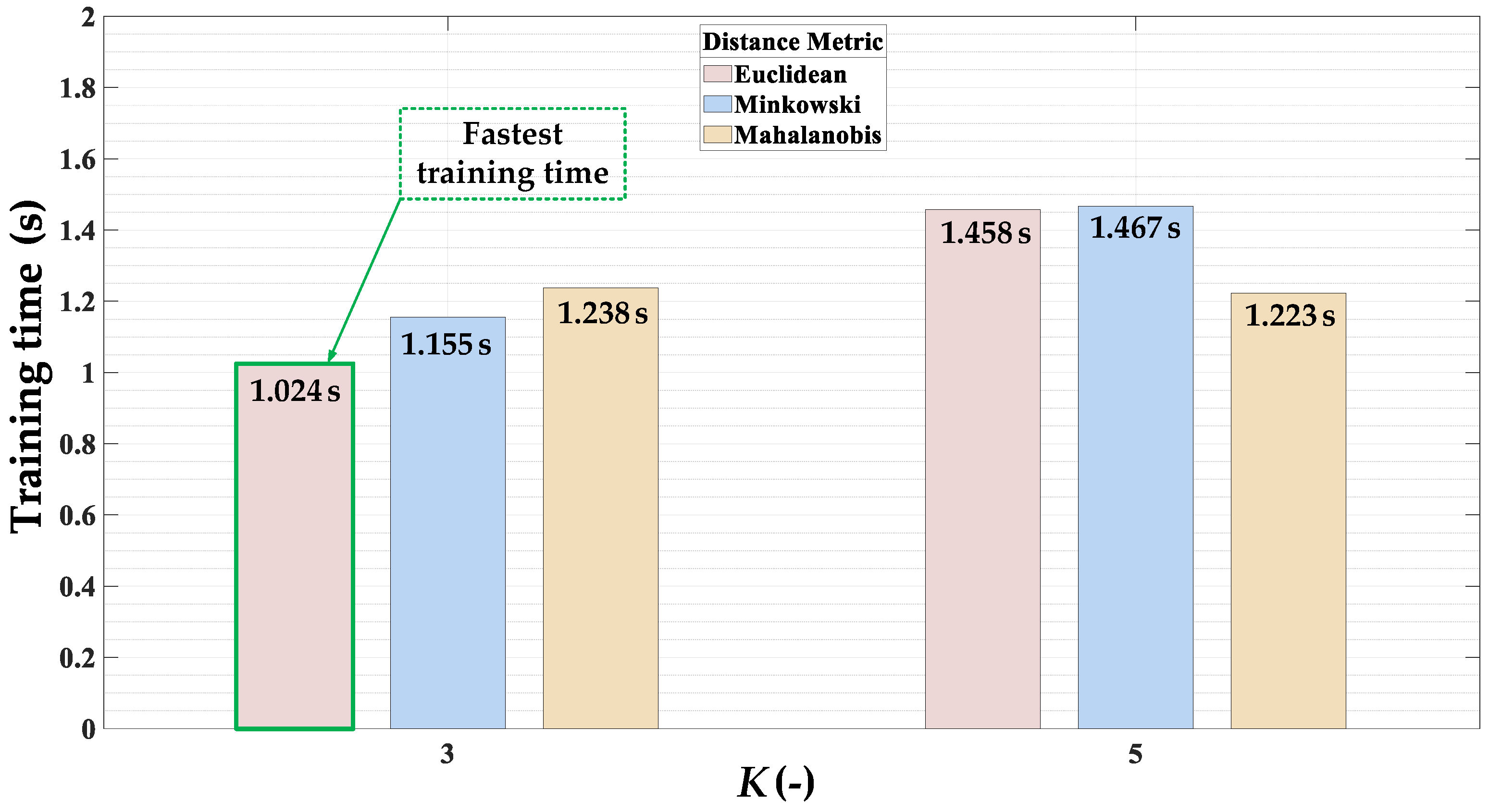
- The KNN classifier training process is very fast;
- The effectiveness of the KNN algorithm depends only on two key parameters: K value and distance metric;
- The KNN algorithm may constantly evolve if new training data are collected;
- In KNN, there are no assumptions about the input data to be met to implement this algorithm.
- The KNN algorithm is generally not recommended for analyzing very large data sets;
- To obtain the proper and effective operation of this algorithm, it is necessary to choose the optimal number of K, which involves the need to test the algorithm several times during the training process;
- It can be challenging to apply the KNN algorithm to high-dimensional data (a high number of features).
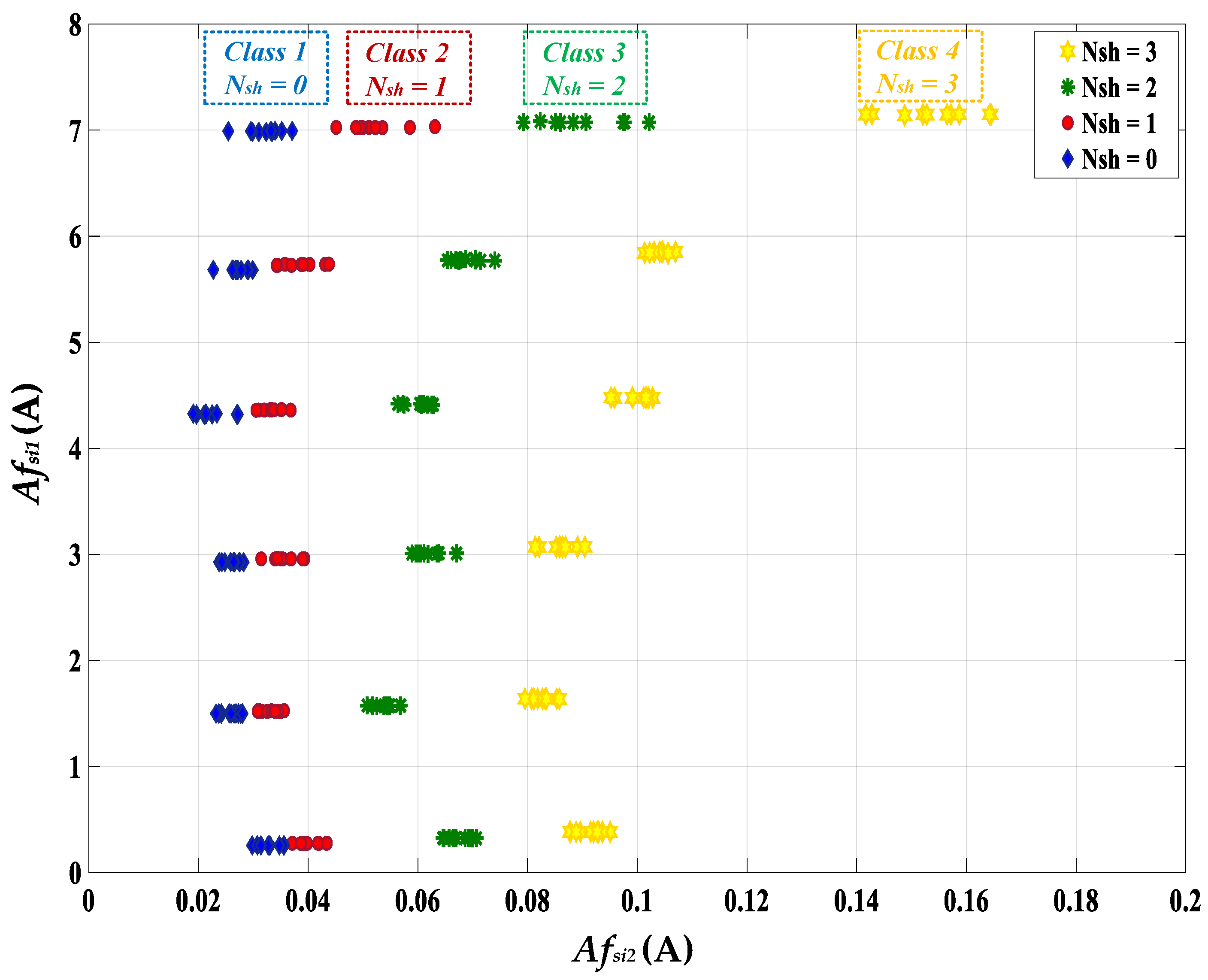
3. Spectral Analysis of Symmetrical Components of Stator Phase Currents
4. Experimental Setup
5. Training Process of the Proposed KNN Fault Classifier
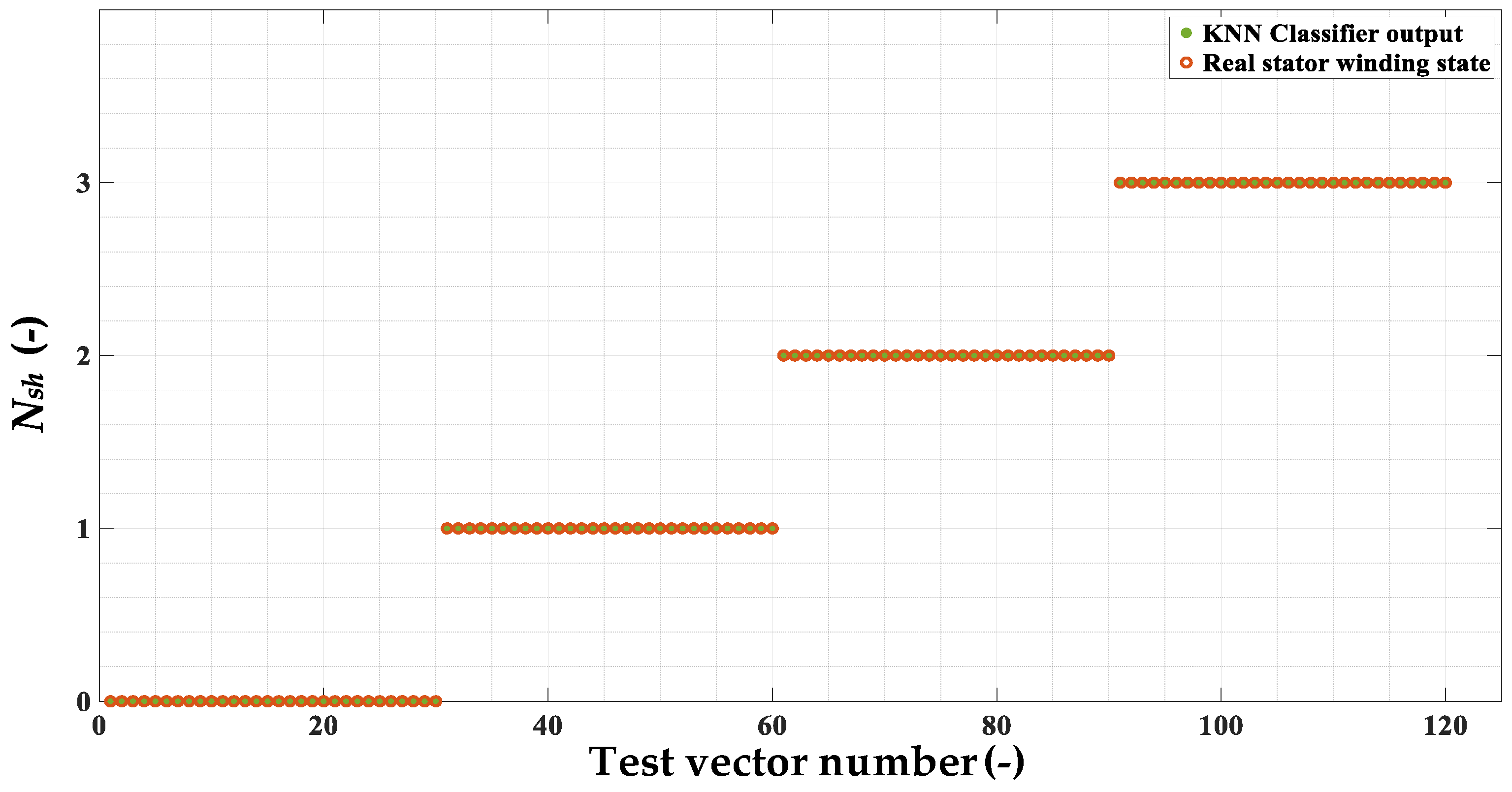
6. The Off-Line and On-Line Verification of the KNN-Based Fault Classifier
7. Conclusions
Author Contributions
Funding
Conflicts of Interest
Appendix A

| Name of the Parameter | Symbol | Units | |
|---|---|---|---|
| Power | PN | 2500 | W |
| Torque | TN | 16 | Nm |
| Speed | NN | 1500 | r/min |
| Stator phase voltage | UsN | 325 | V |
| Stator current | IsN | 6.6 | A |
| Frequency | fsN | 100 | Hz |
| Pole pairs number | pp | 4 | - |
| Number of stator phase turns | Ns | 2 × 125 | - |
References
- Mishra, I.; Tripathi, R.N.; Singh, V.K.; Hanamoto, T. Step-by-Step Development and Implementation of FS-MPC for a FPGA-Based PMSM Drive System. Electronics 2021, 10, 395. [Google Scholar] [CrossRef]
- Gherabi, Z.; Toumi, D.; Benouzza, N.; Henini, N. Modeling and Diagnosis of Stator Winding Faults in PMSM Using Motor Current Signature Analysis. In Proceedings of the 2019 International Aegean Conference on Electrical Machines and Power Electronics (ACEMP) 2019 International Conference on Optimization of Electrical and Electronic Equipment (OPTIM), Istanbul, Turkey, 2–4 September 2019; pp. 227–232. [Google Scholar]
- Hoai, H.-K.; Chen, S.-C.; Than, H. Realization of the Sensorless Permanent Magnet Synchronous Motor Drive Control System with an Intelligent Controller. Electronics 2020, 9, 365. [Google Scholar] [CrossRef] [Green Version]
- Park, G.; Kim, G.; Gu, B.-G. Sensorless PMSM Drive Inductance Estimation Based on a Data-Driven Approach. Electronics 2021, 10, 791. [Google Scholar] [CrossRef]
- He, J.; Somogyi, C.; Strandt, A.; Demerdash, N.A.O. Diagnosis of Stator Winding Short-Circuit Faults in an Interior Permanent Magnet Synchronous Machine. In Proceedings of the 2014 IEEE Energy Conversion Congress and Exposition (ECCE), Pittsburgh, PA, USA, 14–18 September 2014; pp. 3125–3130. [Google Scholar]
- Huang, S.; Aggarwal, A.; Strangas, E.G.; Li, K.; Niu, F.; Huang, X. Robust Stator Winding Fault Detection in PMSMs With Respect to Current Controller Bandwidth. IEEE Trans. Power Electron. 2021, 36, 5032–5042. [Google Scholar] [CrossRef]
- Cira, F.; Arkan, M.; Gümüs, B. A New Approach to Detect Stator Fault in Permanent Magnet Synchronous Motor. In Proceedings of the IEEE International Symposium on Diagnostics for Electric Machines, Power Electronics and Drives (SDEMPED), Guarda, Portugal, 1–4 September 2015; pp. 316–321. [Google Scholar]
- Wolkiewicz, M.; Tarchała, G.; Orłowska-Kowalska, T.; Kowalski, C.T. Online Stator Interturn Short Circuits Monitoring in the DFOC Induction-Motor Drive. IEEE Trans. Ind. Electron. 2016, 63, 2517–2528. [Google Scholar] [CrossRef]
- Drif, M.; Cardoso, A.J.M. Stator Fault Diagnostics in Squirrel Cage Three-Phase Induction Motor Drives Using the Instantaneous Active and Reactive Power Signature Analyses. IEEE Trans. Ind. Inform. 2014, 10, 1348–1360. [Google Scholar] [CrossRef]
- Skowron, M.; Orłowska-Kowalska, T.; Kowalski, C.T. Application of simplified convolutional neural networks for initial stator winding fault detection of the PMSM drive using different raw signal data. IET Electr. Power Appl. 2021, 15, 932–946. [Google Scholar] [CrossRef]
- Usman, A.; Joshi, B.M.; Rajpurohit, B.S. Review of fault modeling methods for permanent magnet synchronous motors and their comparison. In Proceedings of the IEEE International Symposium on Diagnostics for Electric Machines, Power Electronics and Drives (SDEMPED), Tinos, Greece, 29 August–1 September 2017; pp. 141–146. [Google Scholar]
- Rosero, J.; Romeral, L.; Rosero, E.; Urresty, J. Fault Detection in dynamic conditions by means of Discrete Wavelet Decomposition for PMSM running under Bearing Damage. In Proceedings of the Twenty-Fourth Annual IEEE Applied Power Electronics Conference and Exposition, Washington, DC, USA, 15–19 February 2009; pp. 951–956. [Google Scholar]
- Krichen, M.; Elbouchikhi, E.; Benhadj, N.; Chaieb, M.; Benbouzid, M.; Neji, R. Motor Current Signature Analysis-Based Permanent Magnet Synchronous Motor Demagnetization Characterization and Detection. Machines 2020, 8, 35. [Google Scholar] [CrossRef]
- Henao, H.; Capolino, G.A.; Fernandez-Cabanas, M.; Filippetti, F.; Bruzzese, C.; Strangas, E.; Pusca, R.; Estima, J.; Riera-Guasp, M.; Hedayati-kia, S. Trends in Fault Diagnosis for Electrical Machines. IEEE Ind. Electron. Mag. 2014, 8, 31–42. [Google Scholar] [CrossRef]
- Antonino-Daviu, J.A.; Gyftakis, K.N.; Garcia-Hernandez, R.; Razik, H.; Marques Cardoso, A.J. Comparative influence of adjacent and non-adjacent broken rotor bars on the induction motor diagnosis through MCSA and ZSC methods. In Proceedings of the 41st IEEE Industrial Electronics Society (IECON), Yokohama, Japan, 9–12 November 2015; pp. 1680–1685. [Google Scholar]
- Zidani, F.; Benbouzid, M.E.H.; Diallo, D.; Nait-Said, M.S. Induction motor stator faults diagnosis by a current Concordia pattern-based fuzzy decision system. IEEE Trans. Energy Convers. 2003, 18, 469–475. [Google Scholar] [CrossRef] [Green Version]
- Jankowska, K.; Dybkowski, M. A Current Sensor Fault Tolerant Control Strategy for PMSM Drive Systems Based on Cri Markers. Energies 2021, 14, 3443. [Google Scholar] [CrossRef]
- Chen, Y.; Liang, S.; Li, W.; Liang, H.; Wang, C. Faults and Diagnosis Methods of Permanent Magnet Synchronous Motors: A Review. Appl. Sci. 2019, 9, 2116. [Google Scholar] [CrossRef] [Green Version]
- Kyeong-Hwa, K. Simple Online Fault Detecting Scheme for Short-Circuited Turn in a PMSM Through Current Harmonic Monitoring. IEEE Trans. Ind. Electron. 2011, 58, 2565–2568. [Google Scholar]
- Wang, C.-S.; Kao, I.-H.; Perng, J.-W. Fault Diagnosis and Fault Frequency Determination of Permanent Magnet Synchronous Motor Based on Deep Learning. Sensors 2021, 21, 3608. [Google Scholar] [CrossRef]
- Hang, H.; Ding, J.; Zhang, M.; Cheng, W.; Chen, W.; Wang, Q. Detection of Interturn Short-Circuit Fault for PMSM With Simple Fault Indicator. IEEE Trans. Energy Convers. 2016, 31, 1697–11699. [Google Scholar] [CrossRef]
- Park, C.H.; Lee, J.; Ahn, G.; Youn, M.; Youn, B.D. Fault Detection of PMSM under Non-Stationary Conditions Based on Wavelet Transformation Combined with Distance Approach. In Proceedings of the IEEE International Symposium on Diagnostics for Electric Machines, Power Electronics and Drives (SDEMPED), Toulouse, France, 27–30 August 2019; pp. 88–93. [Google Scholar]
- Ping, Z.A.; Juan, Y.; Ling, W. Fault Detection of Stator Winding Interturn Short Circuit in PMSM Based on Wavelet Packet Analysis. In Proceedings of the Fifth International Conference on Measuring Technology and Mechatronics Automation, Hong Kong, China, 16–17 January 2013; pp. 566–569. [Google Scholar]
- Pietrzak, P.; Wolkiewicz, M. Comparison of Selected Methods for the Stator Winding Condition Monitoring of a PMSM Using the Stator Phase Currents. Energies 2021, 14, 1630. [Google Scholar] [CrossRef]
- Hang, J.; Zhang, J.; Xia, M.; Ding, S.; Hua, W. Interturn Fault Diagnosis for Model-Predictive-Controlled-PMSM Based on Cost Function and Wavelet Transform. IEEE Trans. Power Electron. 2020, 35, 6405–6418. [Google Scholar] [CrossRef]
- Maqsood, A.; Oslebo, D.; Corzine, K.; Parsa, L.; Ma, Y. STFT Cluster Analysis for DC Pulsed Load Monitoring and Fault Detection on Naval Shipboard Power Systems. IEEE Trans. Transp. Electrif. 2020, 6, 821–831. [Google Scholar] [CrossRef]
- Wang, H.; Ji, Y. A Revised Hilbert–Huang Transform and Its Application to Fault Diagnosis in a Rotor System. Sensors 2018, 18, 4329. [Google Scholar] [CrossRef] [PubMed] [Green Version]
- Rosero, J.; Ortega, J.; Urrest, J.; Cárdenas, J.; Romeral, L. Stator Short Circuits Detection in PMSM by means of Higher Order Spectral Analysis (HOSA). In Proceedings of the 24th Annual IEEE Applied Power Electronics Conference and Exposition, Piscataway, NJ, USA, 15–19 February 2009; pp. 964–969. [Google Scholar]
- Ewert, P. The Application of the Bispectrum Analysis to Detect the Rotor Unbalance of the Induction Motor Supplied by the Mains and Frequency Converter. Energies 2020, 13, 3009. [Google Scholar] [CrossRef]
- Kia, S.H.; Henao, H.; Capolino, G. A High-Resolution Frequency Estimation Method for Three-Phase Induction Machine Fault detection. IEEE Trans. Ind. Electron. 2007, 54, 2305–2314. [Google Scholar] [CrossRef]
- Sun, L.; Xu, B. An Improved Method for Discerning Broken Rotor Bar Fault and Load Oscillation in Induction Motors. Energies 2018, 11, 3130. [Google Scholar] [CrossRef] [Green Version]
- Trutt, F.C.; Sottile, K.; Kohler, J.L. Online condition monitoring of induction motors. IEEE Trans. Ind. Appl. 2002, 38, 1627–1632. [Google Scholar] [CrossRef]
- Quiroga, J.; Liu, L.; Cartes, D.A. Fuzzy logic based fault detection of PMSM stator winding short under load fluctuation using negative sequence analysis. In Proceedings of the American Control Conference, Seattle, WA, USA, 11–13 June 2008; pp. 1627–1632. [Google Scholar] [CrossRef]
- Ali, M.Z.; Shabbir, M.N.S.K.; Liang, X.; Zhang, Y.; Hu, T. Machine Learning-Based Fault Diagnosis for Single- and Multi-Faults in Induction Motors Using Measured Stator Currents and Vibration Signals. IEEE Trans. Ind. Appl. 2019, 55, 2378–2391. [Google Scholar] [CrossRef]
- Ewert, P.; Orlowska-Kowalska, T.; Jankowska, K. Effectiveness Analysis of PMSM Motor Rolling Bearing Fault Detectors Based on Vibration Analysis and Shallow Neural Networks. Energies 2021, 14, 712. [Google Scholar] [CrossRef]
- Skowron, M.; Orłowska-Kowalska, T. Efficiency of Cascaded Neural Networks in Detecting Initial Damage to Induction Motor Electric Windings. Electronics 2020, 9, 1314. [Google Scholar] [CrossRef]
- Lu, J.; Qian, W.; Li, S.; Cui, R. Enhanced K-Nearest Neighbor for Intelligent Fault Diagnosis of Rotating Machinery. Appl. Sci. 2021, 11, 919. [Google Scholar] [CrossRef]
- Skowron, M.; Wolkiewicz, M.; Orlowska-Kowalska, T.; Kowalski, C.T. Effectiveness of Selected Neural Network Structures Based on Axial Flux Analysis in Stator and Rotor Winding Incipient Fault Detection of Inverter-fed Induction Motors. Energies 2019, 12, 2392. [Google Scholar] [CrossRef] [Green Version]
- Chen, C.-C.; Liu, Z.; Yang, G.; Wu, C.-C.; Ye, Q. An Improved Fault Diagnosis Using 1D-Convolutional Neural Network Model. Electronics 2021, 10, 59. [Google Scholar] [CrossRef]
- Yuan, H.; Wu, N.; Chen, X.; Wang, Y. Fault Diagnosis of Rolling Bearing Based on Shift Invariant Sparse Feature and Optimized Support Vector Machine. Machines 2021, 9, 98. [Google Scholar] [CrossRef]
- Van, M.; Hoang, D.T.; Kang, H.J. Bearing Fault Diagnosis Using a Particle Swarm Optimization-Least Squares Wavelet Support Vector Machine Classifier. Sensors 2020, 20, 3422. [Google Scholar] [CrossRef]
- Ince, T.; Kiranyaz, S.; Eren, L.; Askar, M.; Gabbouj, M. Real-time motor fault detection by 1-D convolutional neural networks. IEEE Trans. Ind. Electron. 2016, 63, 7067–7075. [Google Scholar] [CrossRef]
- Bazan, G.H.; Goedtel, A.; Duque-Perez, O.; Morinigo-Sotelo, D. Multi-Fault Diagnosis in Three-Phase Induction Motors Using Data Optimization and Machine Learning Techniques. Electronics 2021, 10, 1462. [Google Scholar] [CrossRef]
- Shifat, T.A.; Hur, J.-W. ANN assisted multi sensor information fusion for BLDC motor fault diagnosis. IEEE Access 2021, 9, 9429–9441. [Google Scholar] [CrossRef]
- Pietrzak, P.; Wolkiewicz, M. Application of Support Vector Machine to stator winding fault detection and classification of permanent magnet synchronous motor. In Proceedings of the 19th International Power Electronics and Motion Control Conference (PEMC), Gliwice, Poland, 25–29 April 2021; pp. 880–887. [Google Scholar] [CrossRef]
- Xu, X.; Qiao, X.; Zhang, N.; Feng, J.; Wang, X. Review of intelligent fault diagnosis for permanent magnet synchronous motors in electric vehicles. Adv. Mech. Eng. 2020, 12, 1–14. [Google Scholar] [CrossRef]
- Cao, Q.; Gustozzi, F.; Zanni-Merk, C.; de Bertrand de Beuvron, F.; Reich, C. Smart Condition Monitoring for Industry 4.0 Manufacturing Processes: An Ontology-Based Approach. Cybern. Syst. 2019, 50, 82–96. [Google Scholar] [CrossRef]
- Medina-García, J.; Sánchez-Rodríguez, T.; Galán, J.A.G.; Delgado, A.; Gómez-Bravo, F.; Jiménez, R. A Wireless Sensor System for Real-Time Monitoring and Fault Detection of Motor Arrays. Sensors 2017, 17, 469. [Google Scholar] [CrossRef] [Green Version]
- Jiang, Y.; Yin, S.; Dong, J.; Kaynak, O. A Review on Soft Sensors for Monitoring, Control and Optimization of Industrial Processes. Cybern. Syst. 2019, 50, 12868–12881. [Google Scholar] [CrossRef]
- Kumar, P.S.; Xie, L.; Halick, M.S.M.; Vaiyapuri, V. Stator End-Winding Thermal and Magnetic Sensor Arrays for Online Stator Inter-Turn Fault Detection. IEEE Sens. J. 2021, 21, 5312–5321. [Google Scholar] [CrossRef]
- Samanta, S.; Bera, J.N.; Sarkar, G. KNN based fault diagnosis system for induction motor. In Proceedings of the 2nd International Conference on Control, Instrumentation, Energy & Communication (CIEC), Kolkata, India, 28–30 January 2016; pp. 304–308. [Google Scholar] [CrossRef]
- Ali, M.Z.; Shabbir, M.N.S.; Zaman, S.M.K.; Liang, X. Machine Learning Based Fault Diagnosis for Single-and Multi-Faults for Induction Motors Fed by Variable Frequency Drives. In Proceedings of the IEEE Industry Applications Society Annual Meeting, Baltimore, MD, USA, 29 September–3 October 2019; pp. 1–14. [Google Scholar] [CrossRef]
- Surti, K.V.; Naik, C.A. Bearing Condition Monitoring of Induction Motor Based on Discrete Wavelet Transform & K-nearest Neighbor. In Proceedings of the 3rd International Conference for Convergence in Technology (I2CT), Pune, India, 6–7 April 2018; pp. 1–5. [Google Scholar] [CrossRef]
- Okfalisa; Gazalba, I.; Mustakim; Reza, N.G.I. Comparative analysis of k-nearest neighbor and modified k-nearest neighbor algorithm for data classification. In Proceedings of the 2nd International conferences on Information Technology, Information Systems and Electrical Engineering (ICITISEE), Yogyakarta, Indonesia, 1–3 November 2017; pp. 294–298. [Google Scholar] [CrossRef]
- Wang, X.; Jiang, Z.; Yu, D. An Improved KNN Algorithm Based on Kernel Methods and Attribute Reduction. In Proceedings of the 5th International Conference on Instrumentation and Measurement, Computer, Communication and Control (IMCCC), Qinhuangdao, China, 18–20 September 2015; pp. 567–570. [Google Scholar] [CrossRef]
- Hu, L.; Huang, M.W.; Ken, S.W.; Tsai, C.F. The distance function effect on k-nearest neighbor classification for medical datasets. SpringerPlus 2016, 5, 1304. [Google Scholar] [CrossRef] [Green Version]
- Shifat, T.A.; Hur, J. An Improved Stator Winding Short-circuit Fault Diagnosis using AdaBoost Algorithm. In Proceedings of the International Conference on Artificial Intelligence in Information and Communication (ICAIIC), Fukuoka, Japan, 19–21 February 2020; pp. 382–387. [Google Scholar] [CrossRef]
- Saadatfar, H.; Khosravi, S.; Joloudari, J.H.; Mosavi, A.; Shamshirband, S. A New K-Nearest Neighbors Classifier for Big Data Based on Efficient Data Pruning. Mathematics 2020, 8, 286. [Google Scholar] [CrossRef] [Green Version]
- Ma, C.; Du, X.; Cao, L. Improved KNN Algorithm for Fine-Grained Classification of Encrypted Network Flow. Electronics 2020, 9, 324. [Google Scholar] [CrossRef] [Green Version]
- Salvador-Meneses, J.; Ruiz-Chavez, Z.; Garcia-Rodriguez, J. Compressed kNN: K-Nearest Neighbors with Data Compression. Entropy 2019, 21, 234. [Google Scholar] [CrossRef] [PubMed] [Green Version]
- Irvani, M.R.; Karimi-Ghartemani, M. Online estimation of steady state and instantaneous symmetrical components. IET Proc. Gener. Transm. Distrib. 2003, 150, 616–622. [Google Scholar] [CrossRef]
- Bajpai, D.; He, L. Evaluating KNN Performance on WESAD Dataset. In Proceedings of the 12th International Conference on Computational Intelligence and Communication Networks (CICN), Nainital, India, 25–26 September 2020; pp. 60–62. [Google Scholar]


| Training Packages | TL | fS | Nsh |
|---|---|---|---|
| 1 ÷ 60 | 10 vector packages for each: 0, 0.2 TN, 0.4 TN, 0.6 TN, 0.8 TN, TN | 100 Hz (fsN) | 0 |
| 61 ÷ 120 | 10 vector packages for each: 0, 0.2 TN, 0.4 TN, 0.6 TN, 0.8 TN, TN | 1 | |
| 121 ÷ 180 | 10 vector packages for each: 0, 0.2 TN, 0.4 TN, 0.6 TN, 0.8 TN, TN | 2 | |
| 181 ÷ 240 | 10 vector packages for each: 0, 0.2 TN, 0.4 TN, 0.6 TN, 0.8 TN, TN | 3 |
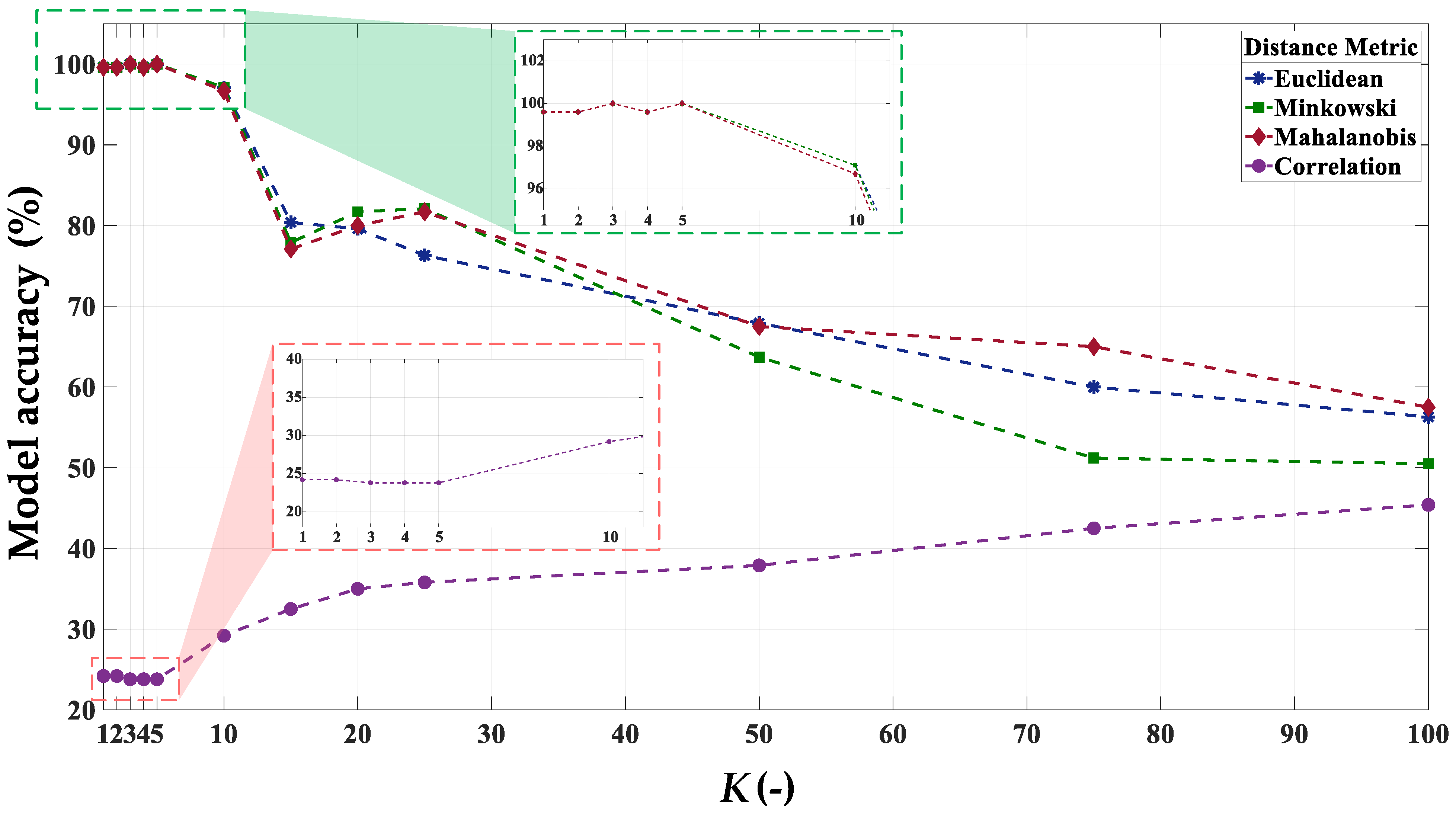
| K (-) | Distance Metric | |||
|---|---|---|---|---|
| Euclidean | Minkowski | Mahalanobis | Correlation | |
| 1 | 99.6% | 99.6% | 99.6% | 24.2% |
| 2 | 99.6% | 99.6% | 99.6% | 24.2% |
| 3 | 100.0% | 100.0% | 100.0% | 23.8% |
| 4 | 99.6% | 99.6% | 99.6% | 23.8% |
| 5 | 100.0% | 100.0% | 100.0% | 23.8% |
| 10 | 97.1% | 97.1% | 96.7% | 29.2% |
| 15 | 80.4% | 77.9% | 77.1% | 32.5% |
| 20 | 79.6% | 81.7% | 80.0% | 35.0% |
| 25 | 76.3% | 82.1% | 81.7% | 35.8% |
| 50 | 67.9% | 63.7% | 67.5% | 37.9% |
| 75 | 60.0% | 51.2% | 65.0% | 42.5% |
| 100 | 56.3% | 50.5% | 57.5% | 45.4% |
| Training Packages | TL | fS | Nsh |
|---|---|---|---|
| 1 ÷ 30 | 5 vector packages for each: 0, 0.2 TN, 0.4 TN, 0.6 TN, 0.8 TN, TN | 100 Hz (fsN) | 0 |
| 31 ÷ 60 | 5 vector packages for each: 0, 0.2 TN, 0.4 TN, 0.6 TN, 0.8 TN, TN | 1 | |
| 61 ÷ 90 | 5 vector packages for each: 0, 0.2 TN, 0.4 TN, 0.6 TN, 0.8 TN, TN | 2 | |
| 91 ÷ 120 | 5 vector packages for each: 0, 0.2 TN, 0.4 TN, 0.6 TN, 0.8 TN, TN | 3 |
| Test Scenario | Description | fS | Nsh | TL |
|---|---|---|---|---|
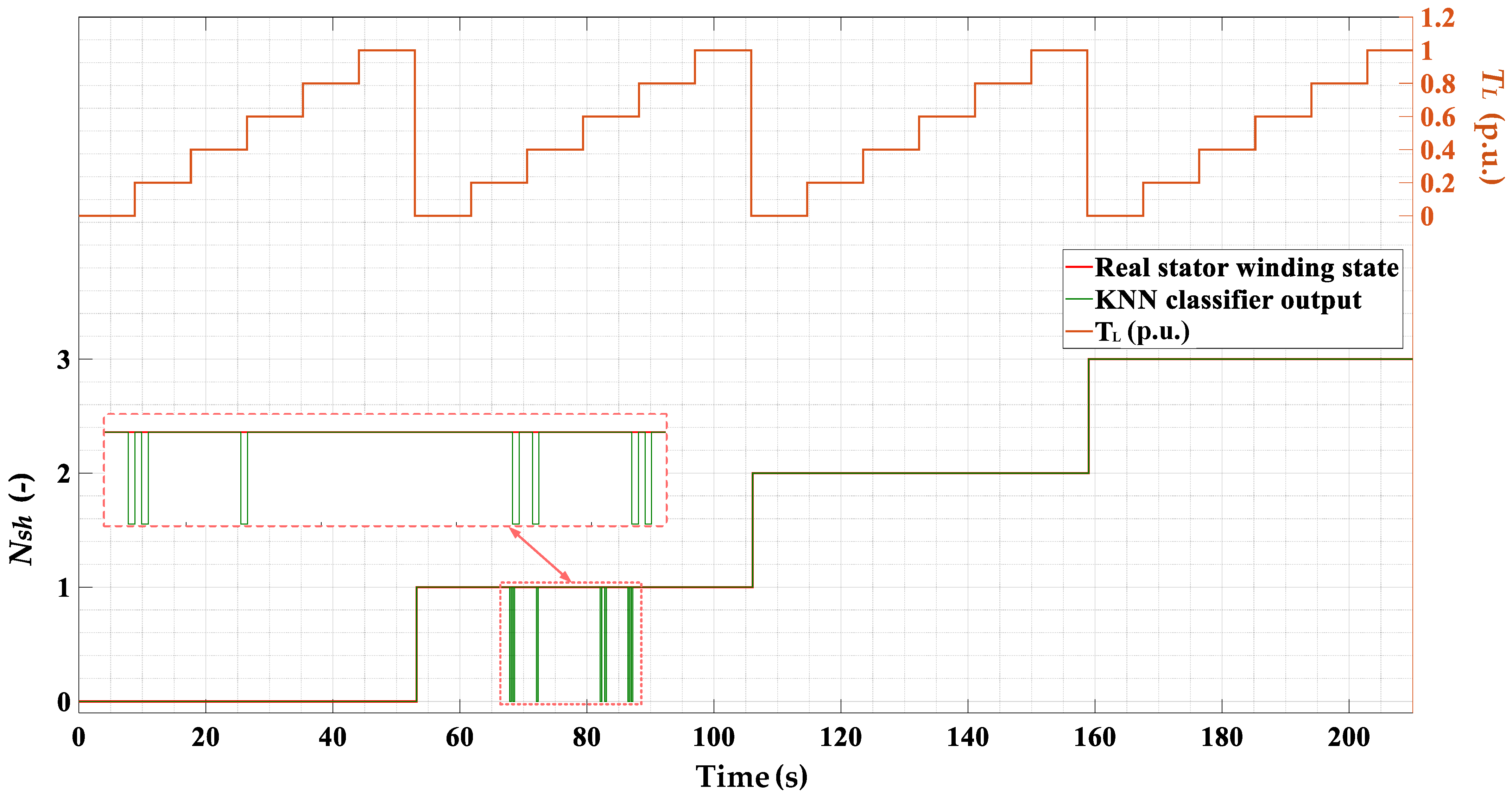
| 1 | One, two and three turns were short circuited for several seconds (steady short-circuits). The motor was operating under the following conditions: TL = (0 ÷ 1)TN with a 0.2TN step and nominal supply frequency. | 100 Hz (fsN) | 0; 1; 2; 3 | var |
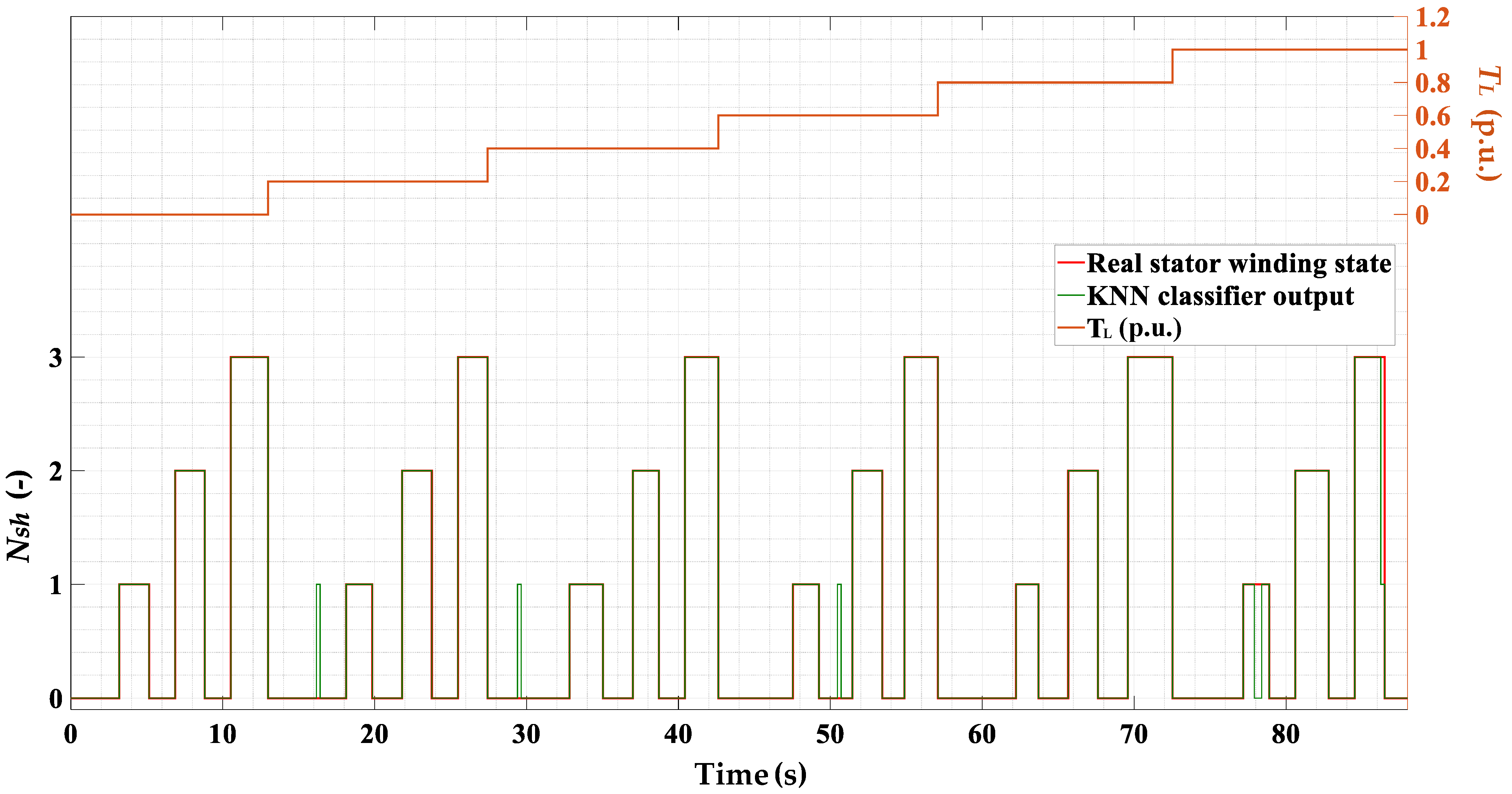
| 2 | The momentary (for 1 ÷ 2 s) short-circuiting of one, two and three shorted turns was conducted. The motor was operating under the following conditions: TL = (0 ÷ 1)TN with a 0.2TN step and nominal supply frequency. | 100 Hz (fsN) | 0; 1; 2; 3 | var |
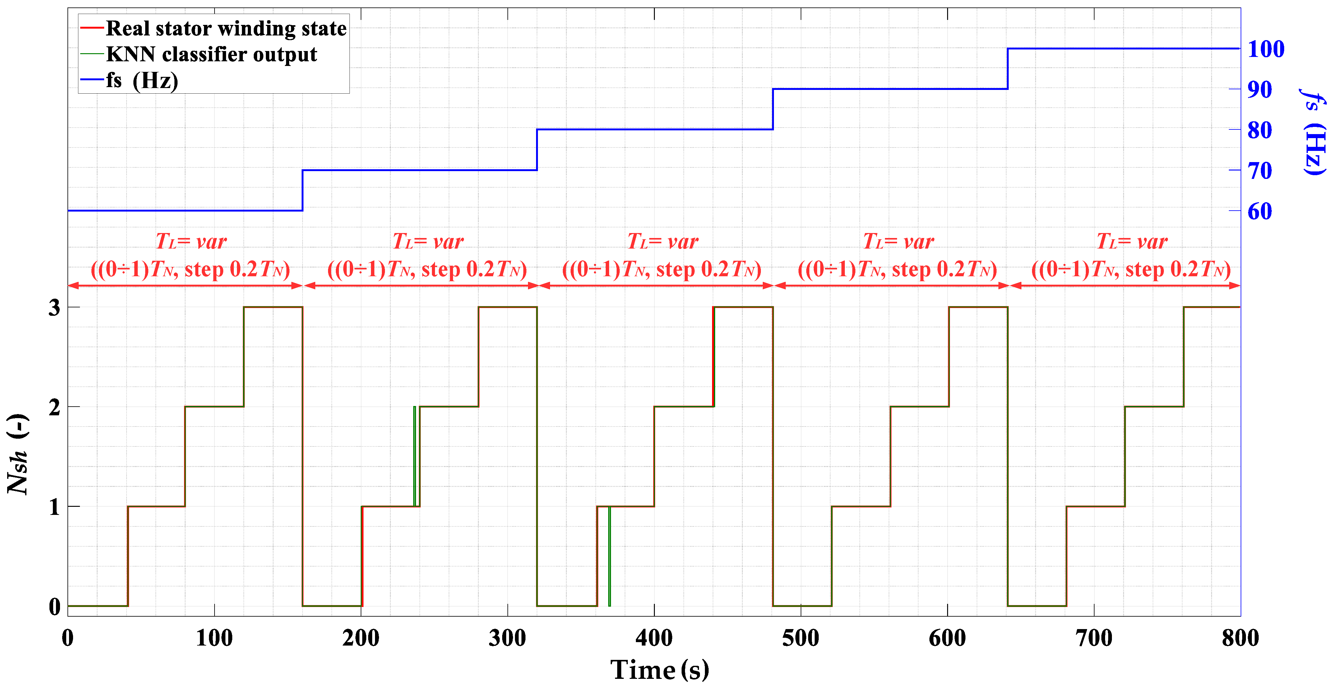
| 3 | One, two and three turns were short circuited for several seconds (steady short-circuits). The motor was operating under the following conditions: TL = (0 ÷ 1)TN with a 0.2TN step and fs = (60 ÷ 100) Hz with 10Hz step. | var | 0; 1; 2; 3 | var |
| Parameter | Value |
|---|---|
| Accuracy | 100% |
| Validation (off-line test) | 100% |
| CEFF (On-Line Test 1) | 99.3% |
| CEFF (On-Line Test 2) | 98.6% |
| CEFF (On-Line Test 3) | 99.5% |
| Average CEFF | 99.1% |
| Distance metric | Euclidean |
| Distance weight | Equal |
| K | 3 |
| Training time | 1.024 s |
Publisher’s Note: MDPI stays neutral with regard to jurisdictional claims in published maps and institutional affiliations. |
© 2021 by the authors. Licensee MDPI, Basel, Switzerland. This article is an open access article distributed under the terms and conditions of the Creative Commons Attribution (CC BY) license (https://creativecommons.org/licenses/by/4.0/).
Share and Cite
Pietrzak, P.; Wolkiewicz, M. On-line Detection and Classification of PMSM Stator Winding Faults Based on Stator Current Symmetrical Components Analysis and the KNN Algorithm. Electronics 2021, 10, 1786. https://0-doi-org.brum.beds.ac.uk/10.3390/electronics10151786
Pietrzak P, Wolkiewicz M. On-line Detection and Classification of PMSM Stator Winding Faults Based on Stator Current Symmetrical Components Analysis and the KNN Algorithm. Electronics. 2021; 10(15):1786. https://0-doi-org.brum.beds.ac.uk/10.3390/electronics10151786
Chicago/Turabian StylePietrzak, Przemyslaw, and Marcin Wolkiewicz. 2021. "On-line Detection and Classification of PMSM Stator Winding Faults Based on Stator Current Symmetrical Components Analysis and the KNN Algorithm" Electronics 10, no. 15: 1786. https://0-doi-org.brum.beds.ac.uk/10.3390/electronics10151786